


Abstract
This experimental study comparatively investigates flow boiling performance and mechanisms in open and closed rectangular microchannels (ORMs/CRMs) with a high aspect ratio of 4. Fabricated on a copper substrate and sealed with a transparent window for visualization, the systems were tested using refrigerant R245fa. Experiments spanned mass fluxes from 89 to 545 kg/m2·s and heat fluxes from 6.3 to 218.5 W/cm2 at an inlet temperature of 14 °C. Flow visualization reveals that the ORM configuration accelerates the transition from bubbly to slug and churn flow regimes and facilitates a unique stratified flow pattern absent in the CRM. Quantitatively, the ORM enhances the heat transfer coefficient by 4.2–14.1% while reducing the system pressure drop by 11.5–58.6% within the low mass flux range (89–269 kg/m2·s). Conversely, at a high mass flux of 545 kg/m2·s, the ORM’s pressure drop increases substantially by 29.9–246.8%, attributed to significant two-phase losses in the top-gap region. As heat flux increases, inertial forces dominate over gravitational effects, shifting the primary heat transfer contribution from nucleate to flow boiling. The figure of merit (FOM) confirms the overall performance superiority of the ORM at low mass fluxes. This work provides valuable insights and design guidelines for high-performance, high-aspect-ratio microchannel heat sinks in advanced thermal management systems.
1. Introduction
With the advancement of technology, the demand for high-heat-flux dissipation in miniaturized and compact systems such as high-performance computer chips, nuclear fission reactors, and aerospace integrated circuits has been increasing [1,2,3,4]. Conventional single-phase cooling techniques are increasingly incapable of meeting these stringent thermal requirements, particularly under constrained footprints and limited allowable temperature rise.
Silicon-based microchannel heat sinks, first developed by Tuckerman and Pease [5], provide an effective technological solution for removing high heat fluxes from miniaturized devices. Due to the excellent heat dissipation properties of microchannels, many researchers have focused on designing them to enhance heat transfer. To improve heat transfer performance, numerous studies have investigated disturbed flow structures that disrupt the normal development of the boundary layer. These perturbed structures can be categorized into various types, including micro pin fins of different shapes and cross-linked microchannel structures [6]. These structures include square silicon micro pin fins [7,8], micro oblique pin fins [9,10], circular micro pins [11], diamond micro pin fins [12], piranha pin fins [13,14], cross-linked triangular longitudinal microchannels [15,16], and others. Although these structures can enhance heat transfer by disrupting boundary-layer development and alleviating partial bubble blockage, they inevitably incur substantial pressure drop penalties. More importantly, the fundamental issue of flow boiling instability persists, as rapid vapor generation and confined bubble expansion are not fundamentally alleviated.
Microchannels with large aspect ratios (ARs) enhance thermal dissipation by increasing the solid–liquid contact area within equivalent footprints. Fu et al. [17] investigated HFE-7100 boiling heat transfer in copper microchannels, revealing that critical heat flux (CHF) initially increases and then decreases with AR, peaking at AR = 0.99. In contrast, Makal et al. [18] observed the maximum water heat transfer coefficient at AR = 3.54. For high-AR configurations, Yin et al. [19] demonstrated nuclear boiling dominance in water flow boiling, with sweeping/churn flows exhibiting superior heat transfer coefficients. Cui et al. [20] developed ultrahigh-AR copper microchannels (AR = 25) showing 40.95% CHF enhancement and 40.28% thermal resistance reduction compared to AR = 1 channels. The heat transfer coefficient displayed a characteristic dip–rise pattern governed by synergistic nuclear boiling and thin-film evaporation. Drummond et al. [21] identified vapor blanketing effects in high-aspect-ratio manifold microchannels that induced surface dewetting, while narrow confinement exacerbated flow instability due to uncontrolled bidirectional bubble expansion. To address flow boiling instabilities originating from confined vapor expansion, recent studies have emphasized providing additional vapor accommodation pathways or selectively separating excessive vapor from the liquid flow. By decoupling vapor generation from liquid transport, such approaches can effectively suppress pressure oscillations, flow reversal, and intermittent dryout.
Cheng et al. [22,23] demonstrated that interconnected microchannels provide additional bubble growth and expansion space, significantly advancing the onset of nucleate boiling and enhancing CHF by up to 59.15% compared with plain microchannels. More recently, passive vapor venting techniques have attracted increasing attention. Zhang et al. [24] developed a membrane-venting microchannel heat sink, in which excessive vapor was evacuated through a hydrophobic membrane, resulting in reduced pressure drop and markedly improved flow stability. Similarly, Priy et al. [25] reported that passive vapor venting using a superhydrophobic mesh effectively suppressed large vapor slug formation, converting low-frequency, high-amplitude oscillations into more stable high-frequency fluctuations.
Open microchannels, characterized by partial or complete removal of top confinement, provide additional space for bubble growth and vapor escape, thereby alleviating confinement-induced instabilities while enhancing boiling heat transfer performance. Following Cook et al.’s seminal concept [26], Kandlikar’s group pioneered volumetrically tapered open microchannel evaporators [27]. Kalani’s systematic investigations [28,29,30] demonstrated that tapered open microchannels achieve stable heat transfer with exceptionally low pressure drop, sustaining 506 W/cm2 at 26.2 °C wall superheat without reaching CHF. Balasubramanian et al. [31] confirmed negligible orientation effects on flow boiling within the 77–911 kg/m2s mass flux range. Alyssa et al. [32] reduced two-phase pressure drop by 18–22% using radial open microchannels compared to straight channels. Kadam et al. [33] reported 9–18% single-phase heat transfer enhancement in expanded open microchannels versus flat-plate configurations. Xia et al. [34] observed suppressed wall overshoot during ONB in semi-open structures. Zhao et al. [35] visualized wettability effects, identifying super-hydrophilic open microchannels with superior high-heat-flux performance. Bhandari et al. [36] numerically determined optimal fin heights (75–80% of closed-channel values) for variable-fin open microchannels. Yin et al. [37,38] examined the flow pattern and heat transfer characteristics of two-phase boiling in open microchannels, proposing two stratified flow patterns unique to open microchannel heat sinks. Qiu et al. [39] also observed stratified flow in designed open microchannels with inclined fins. Zhao et al. [40] synergized leaf-vein architectures with open channels for heat transfer enhancement without pressure penalty. Although extensive studies have been conducted on the boiling heat transfer characteristics of two-phase flow boiling in open microchannels, two critical limitations persist: (1) The flow boiling and instability characteristics of large-aspect-ratio open microchannels are still insufficiently understood under high-heat-flux conditions. (2) In many existing studies, structural parameters differ significantly between open and closed configurations, making it difficult to isolate the intrinsic effect of additional vapor space from other geometric variations.
In this study, an ORM with a large aspect ratio and a CRM with the same heat transfer structure were designed to investigate the effect of the top-gap structure on flow boiling behavior, heat transfer performance, and flow instability characteristics in large-aspect-ratio microchannels. Flow boiling experiments were conducted on the ORM under different operating conditions, and the heat transfer and pressure drop characteristics were compared with those of the CRM. Additionally, a visualization study of the flow boiling inside the microchannel was performed to analyze the impact of the top-gap on the boiling mechanism. To better quantify the effect of the top gap structure on the overall performance of high-aspect-ratio rectangular microchannels, instability analysis and the FOM were introduced.
2. Experimental Setup
2.1. Flow Loop
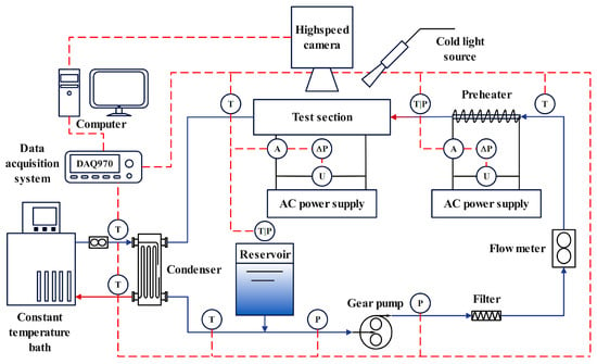
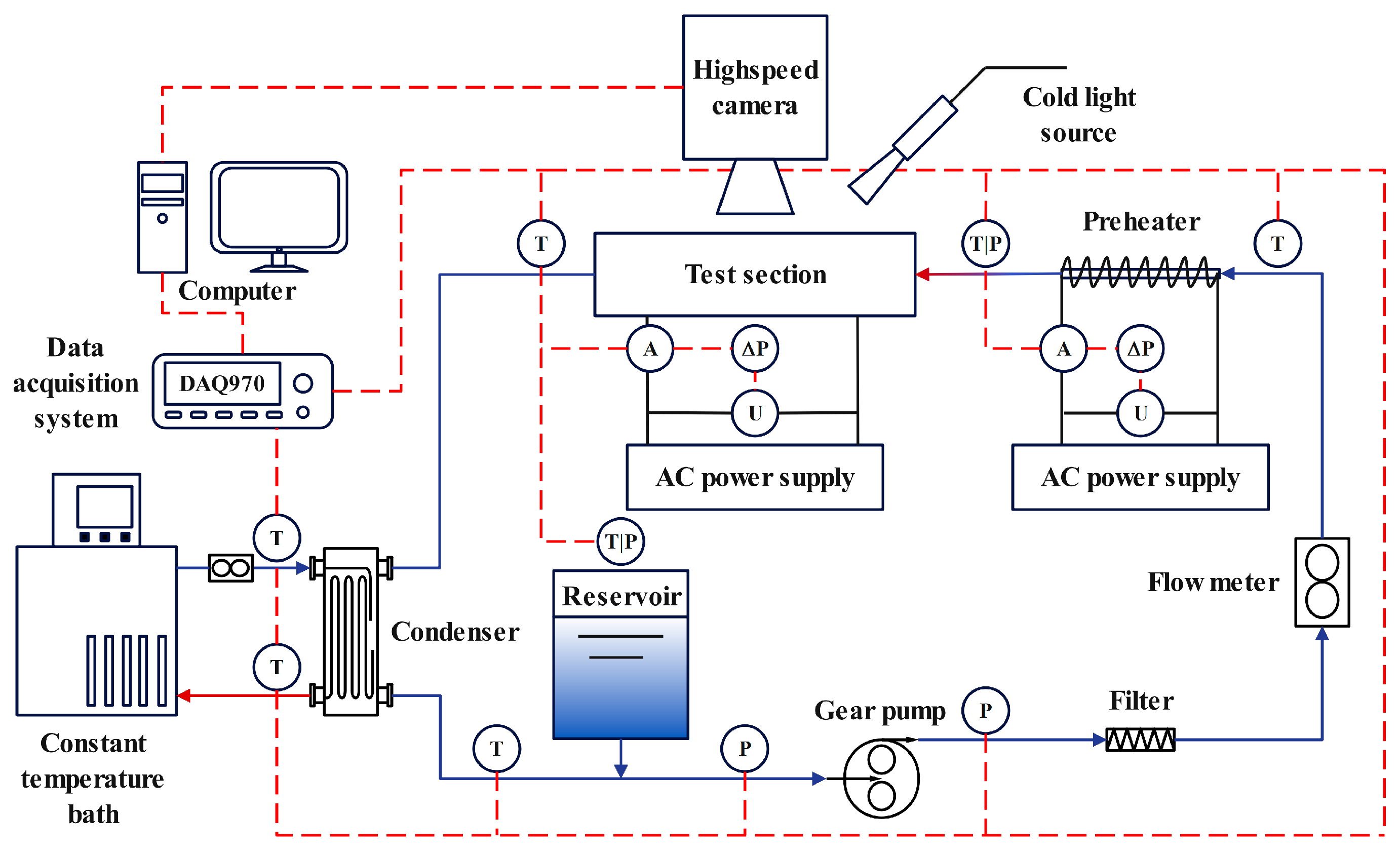
The schematic diagram of the system loop is shown in Figure 1. The experimental setup consists of three main subsystems: the liquid circulation loop, the heating system, and the data acquisition system. The working fluid, R245fa, stored in the reservoir flows sequentially through a gear pump, an inline filter, and a volumetric flow meter and is then heated and temperature-controlled by a preheater before entering the evaporator. The working medium flowing out of the evaporator is cooled by the condenser, and then it flows back into the pump inlet, completing one flow cycle. The constant-temperature water bath provides cooling capacity for the condenser. Pressure transmitters and thermocouples are, respectively, set at the inlet and outlet of the evaporator, pump, and condenser to detect the changes in pressure and temperature within the system. Meanwhile, differential pressure transmitters are installed at both ends of the evaporator. The heating system consists of an evaporator heating block and a preheater, which are, respectively, powered by AC, and voltage and current sensors are set at the current output position. Agilent’s acquisition card is selected as the data acquisition system to collect the temperature, voltage, current, pressure, and pressure difference signals in the system. Meanwhile, a high-speed camera and light source are set on the side of the evaporator to capture the boiling situation of the flow in the microchannel along the flow direction. The parameters of the relevant equipment used in the experimental system are shown in Table 1.
Figure 1.
Schematic drawing of the experimental flow loop.
Table 1.
The specifications of main experimental equipment.
2.2. Test Section
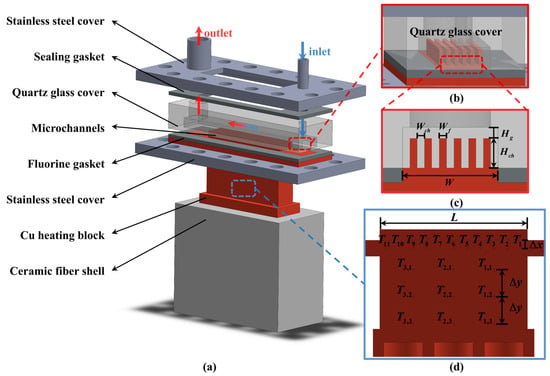
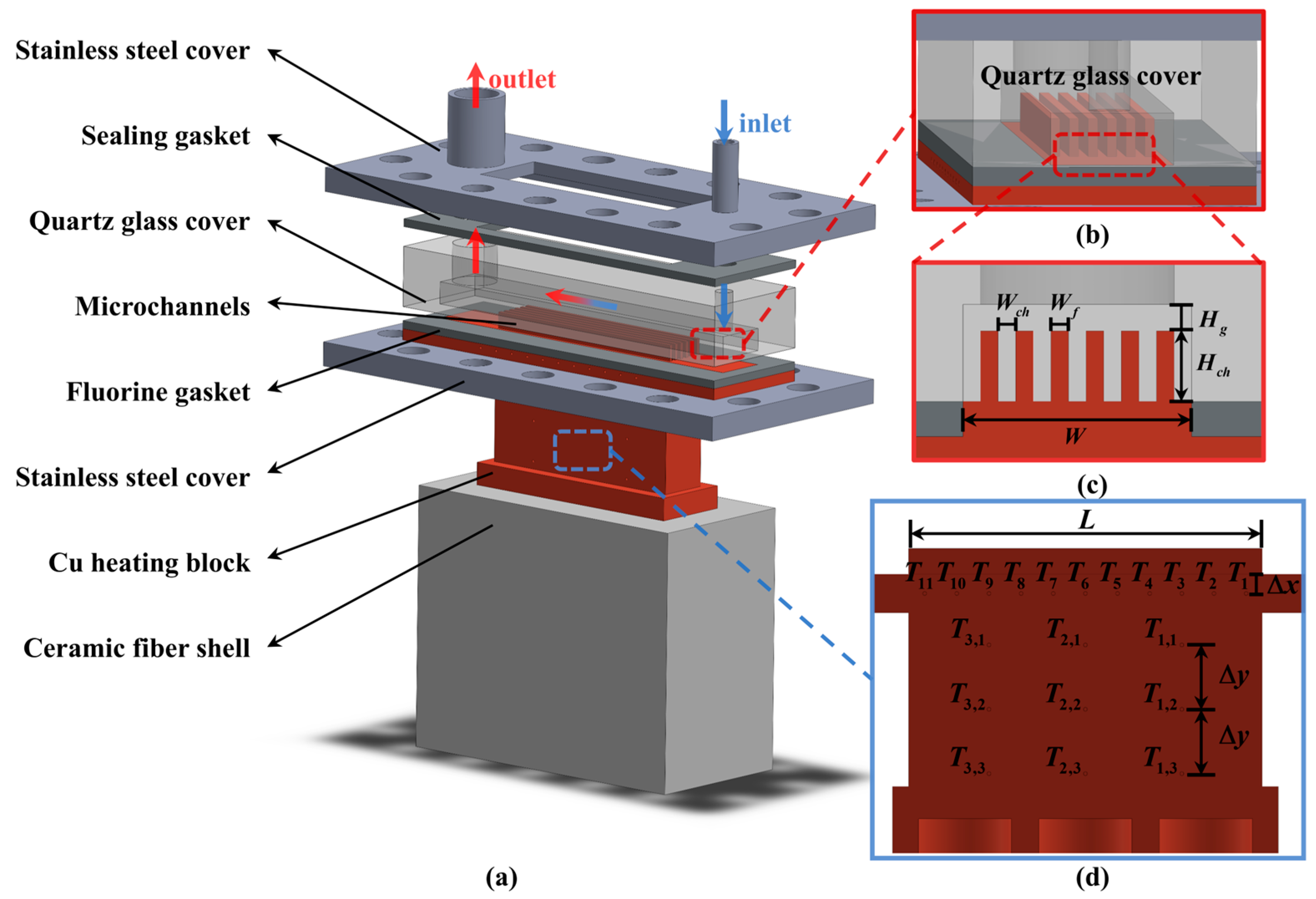
The schematic diagram of the test section is shown in Figure 2. The test section consists of a stainless-steel cover, sealing gaskets, a quartz glass window, microchannels, a heating section, and an insulation layer. Two 316 stainless-steel tubes are welded to the stainless-steel cover, serving as the inlet and outlet. Fluorine gaskets are used between the quartz window, microchannels, and stainless-steel cover to provide sealing and thermal insulation. Both the steel cover and heating block are machined with positioning grooves. Fourteen mounting holes are drilled on the cover for bolted connections between components. The heating block is encased in a ceramic fiber shell for thermal insulation. A transparent quartz glass window allows for an observation of the fluid flow and boiling behavior within the microchannels. The heating block is made of copper and is equipped with three heating rods, each with a maximum power of 700 W. The thermal conduction section between the heating block and the microchannels measures 55 mm × 13 mm × 27 mm (length × width × height).
Figure 2.
Schematic diagram of test module. (a) Evaporator structure and components, (b) top view of the microchannel, (c) microchannel dimensions, (d) thermocouple locations.
The microchannels are fabricated using Wire Electrical Discharge Machining (WEDM). The schematic and cross-sectional dimensions of the open rectangular microchannel evaporator are shown in Figure 2 b,c, respectively. The ORM consists of 7 parallel channels, each with dimensions of 1 mm × 4 mm (width × height) ( × ), and a fin width () of 1 mm. The top-gap height () refers to the distance between the top of the heat transfer fins and the quartz glass cover. The thermocouple arrangement is shown in Figure 2d. At a position 3 mm () from the bottom of the central microchannel, thermocouples are placed at 5 mm intervals with a hole diameter of 0.6 mm. The thermal conduction section is equipped with 9 thermocouple holes, with horizontal spacing of 15 mm and vertical spacing of 10 mm (). All thermocouple holes are located in the same plane. Thermal grease is applied to the installation points of the thermocouples and heating rods to minimize thermal contact resistance. The footprint of the ORM is 55 mm × 13 mm (length × width). Detailed geometric specifications of the ORM are summarized in Table 2. For the CRM, is 0, while all other structural dimensions are the same as those of the ORM.
Table 2.
Geometric dimensions of ORM.
2.3. Experimental Procedure
Prior to conducting the experimental study, the thermocouples, pressure sensors, differential pressure sensors, voltage sensors, current sensors, and flow meters were calibrated. Subsequently, flow boiling experiments and corresponding visualization studies were conducted on both the ORM and CRM. The tests covered mass fluxes ranging from 89 to 545 kg/m2·s and heat fluxes from 6.3 to 218.5 W/cm2, under a constant evaporation temperature of 20 °C and an inlet subcooling corresponding to an inlet temperature of 14 °C. The data acquisition system was activated, followed by the sequential startup of the gear pump, condenser, preheater, and heater block. The system parameters were then adjusted to the specified operating conditions. Once the temperature in the test section stabilized for over 2 min, flow boiling inside the microchannel was captured using a high-speed camera. The heating power was then adjusted to transition to the next operating condition. When a rapid temperature rise was observed on the test section wall, the heater block’s AC power was immediately turned off, and the flow rate was increased to cool the test section, marking the completion of that experimental set.
3. Data Reduction
3.1. Heat Transfer Calculation
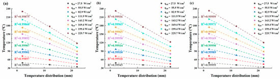
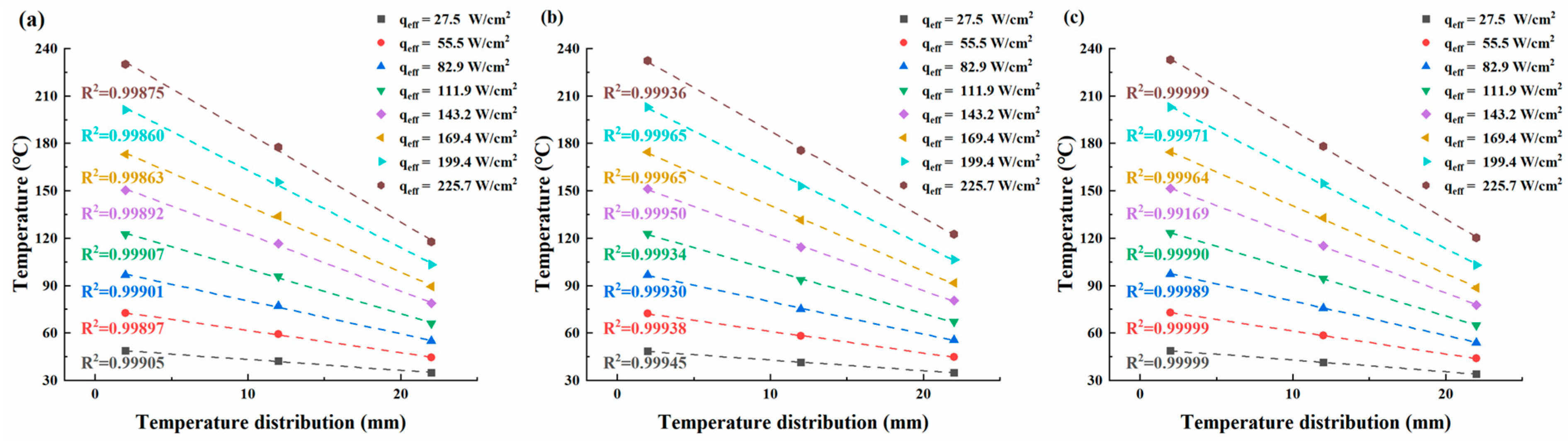
When the working fluid R245fa, with a mass flux of G = 504 kg/m2·s, flows through the ORM featuring a top volume space height of 0.9 mm for boiling heat transfer, the measured temperatures along the axis of the variable diameter section of the copper block under different heat fluxes (27.5–225.7 W/cm2) are illustrated in Figure 3.
Figure 3.
Distribution of temperature along the axis of a copper block at different heat fluxes for boiling at G = 504 kg/m2·s. (a) Below the entrance to the ORM; (b) down the middle of the ORM; (c) below the ORM exit.
Figure 3a–c depict axial temperature profiles near the entrance, middle, and exit of the ORM, respectively. The drawn lines represent the linear fitting results of the temperature data, with coefficients of determination (R2) exceeding 0.99. This indicates that the copper heating block selected in the experiment has excellent one-dimensional thermal conductivity performance. Therefore, the effective heat load () along the axial direction of the copper block can be simplified and calculated using Fourier’s one-dimensional law [41,42]. The calculation formula is as follows:
where is the cross-sectional area of the thermal conduction section, is the thermal conductivity of copper, and is the temperature gradient in the direction of heat propagation. The temperature gradient is calculated from a three-point backward difference Taylor series approximation using the thermal conduction section temperatures , , and , each at a distance of 10 mm apart [37]. , , and are the upper and lower temperatures along the thermal conduction section with a distance of 20 mm.
The heat loss is mainly caused by natural convection over a finite area and thermal leakage through insulation materials. The thermal conductivity of the Cu copper block is 396 W/(m⋅K). The range of heat loss within the variation in effective heat load is 1.3%~12.9%. The effective heat flux () is determined as follows [43]:
where is the contact area of the microchannels on the copper substrate, and L and W are the length and total width of the microchannels, respectively. The following equation is used to calculate the two-phase heat transfer coefficient:
where represents the saturation temperature of the refrigerator at the outlet pressure, and is the average temperature of the contact wall at the bottom of the microchannels, which is given by the Fourier law as follows:
where is defined as the length from the temperature measurement point to the bottom wall of the microchannels. Additionally, the wall superheat () is calculated by the following formula:
The mean outlet vapor quality is determined through a process of calculating the energy balance of the working fluid at both the inlet and outlet points along the test section. The resulting equation is as follows:
where is the specific heat of working fluid at the outlet pressure, represents the latent heat of working fluid at the outlet pressure, denotes the inlet liquid temperatures, and is the mass flow rate.
3.2. Pressure Drop
Owing to the positioning of pressure differential sensors upstream of the inlet static pressure chamber and downstream of the outlet static pressure chamber in the ORM test section, the measured pressure difference reflects the cumulative losses due to two-phase flow pressure drop, inlet contraction, and outlet expansion within the ORM. Consequently, the two-phase pressure drop across the ORM is calculated according to the following procedure:
where , , and are the total pressure drop of the evaporator, the inlet contraction pressure drop, and the outlet expansion pressure drop, respectively. and were evaluated according to the means mentioned in the previous study [44].
The ORM utilized in this experiment features a substantial aspect ratio of 4, characterized by a channel height of 4 mm, which results in heightened frictional resistance. As a result, the pressure losses at the inlet and outlet sections play a pivotal role in the total pressure drop across the evaporator, constituting a maximum of 29.9%. Hence, these pressure losses warrant significant consideration.
3.3. Experimental Uncertainties
Experimental uncertainties include several factors, including test section fabrication uncertainties, sensor measurement uncertainties, and inferred measured parameter uncertainties. Manufacturing uncertainties were estimated to be within ±0.10 mm. All sensors underwent calibration before experimentation. Measurement uncertainties such as pressure, temperature, and flow rate were determined by the precision of the pressure transducers, temperature sensors, and flow meter, respectively, based on the manufacturer’s specifications and experimental data. Uncertainties in calculated parameters such as heat flux, heat transfer coefficient, or surface temperature propagate from component uncertainties involved in their computation. The standard uncertainty analysis method described by Moffat [45] was employed to assess derived uncertainties. Table 3 provides a summary of the maximum relative uncertainties in the current study.
Table 3.
Uncertainties of the measured and calculated parameters.
4. Results and Discussion
4.1. Flow Pattern Analysis
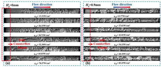
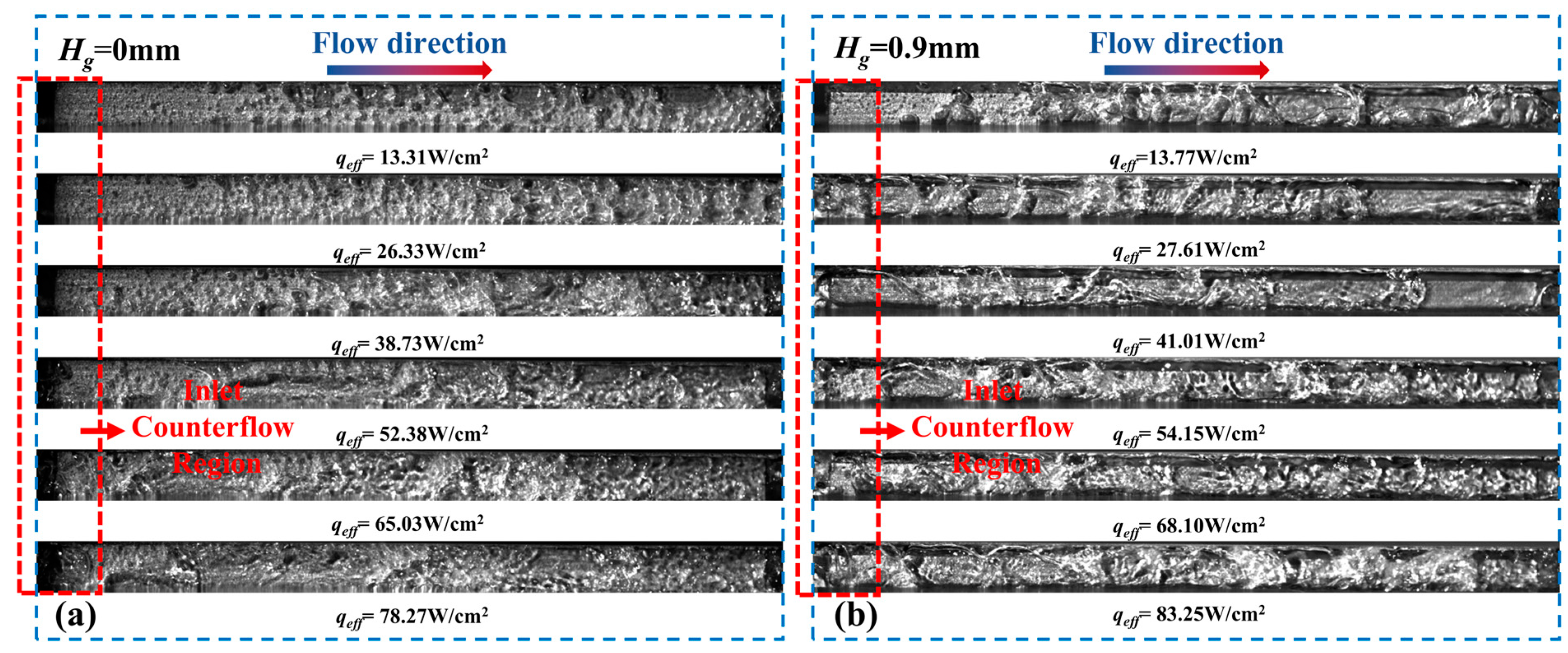
During flow boiling, the evolution of flow patterns reflects changes in the dominant heat transfer mechanisms and plays a critical role in determining thermal performance [38]. Figure 4 shows the flow regime transitions captured by a high-speed camera located at the side of the microchannel. At a mass flux of 179 kg/m2·s, the bubbles observed in the CRM are noticeably smaller than those in the ORM. In the CRM, the flow pattern evolves sequentially from bubbly flow to slug flow, and eventually to churn flow as the heat flux increases. At low heat flux, the bubble nucleation density and detachment frequency on the heated wall and fins are relatively low, resulting in a low two-phase heat transfer coefficient (HTC). With increasing heat flux, bubble nucleation becomes more intense and bubbles coalesce into larger vapor structures, causing the dominant flow regime to shift toward elongated bubble flow. In this regime, thinning of the liquid film on the heated surface enhances film evaporation, leading to improved heat transfer. Further increases in heat flux intensify vapor activity, which disturbs the liquid film, reduces thermal resistance, and promotes more effective heat dissipation. This stage corresponds to the onset of churn flow. When liquid rewetting becomes insufficient, vapor accumulates on the heated surface, forming a vapor film and initiating local dryout. At sufficiently high heat flux, this process ultimately leads to burnout.
Figure 4.
Flow regimes for flow boiling in (a) CRM and (b) ORM at G = 179 kg/m2·s.
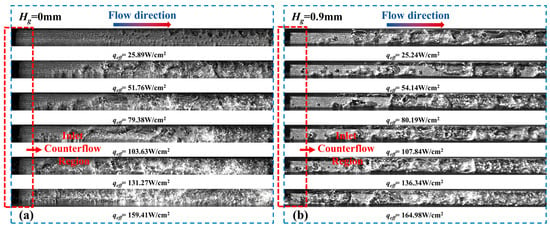
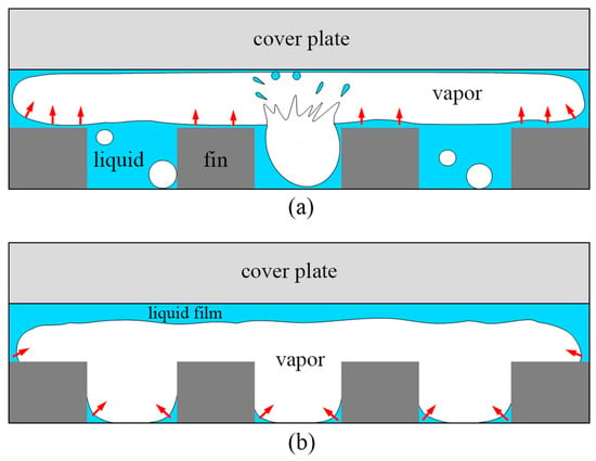
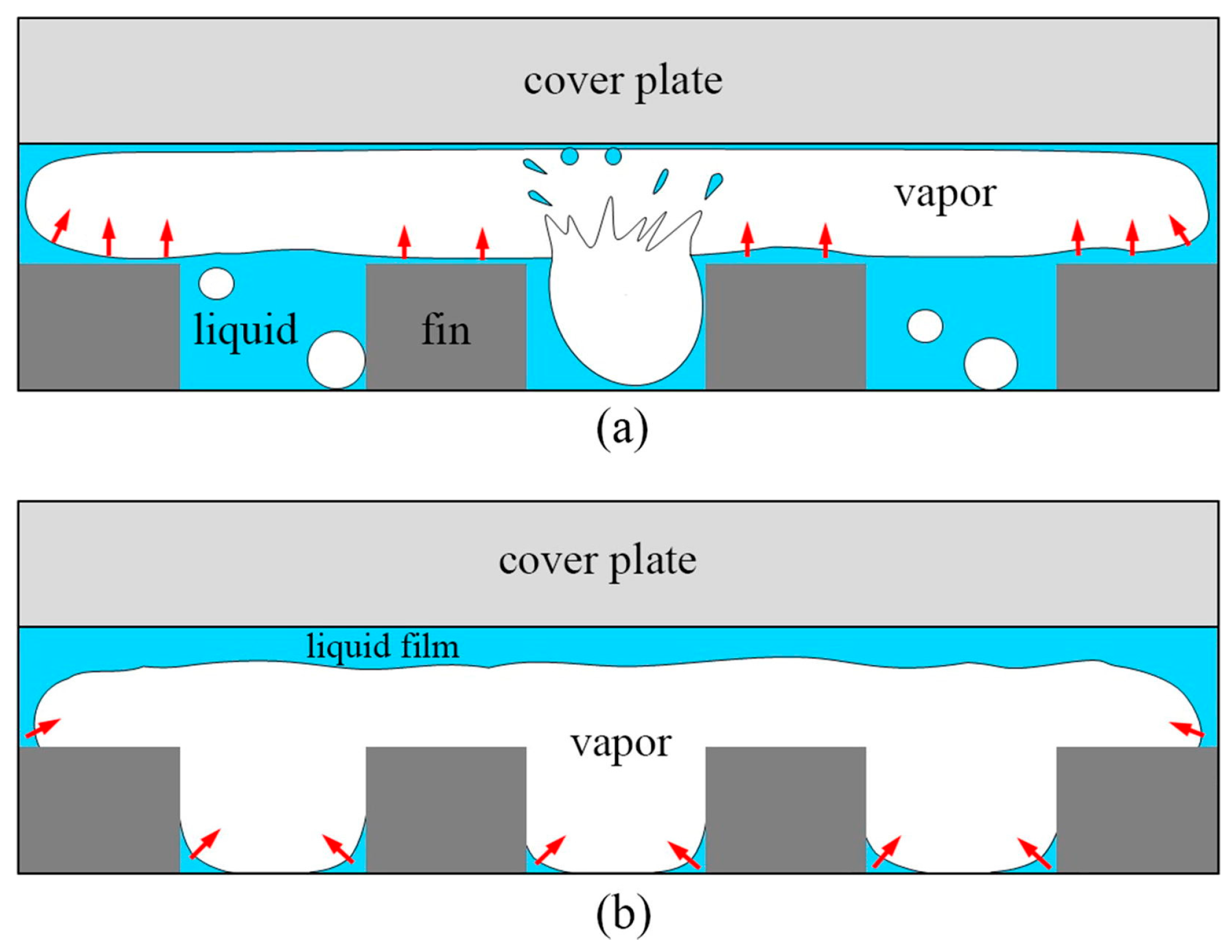
In contrast, the ORM exhibits distinct flow characteristics due to the presence of a top-gap region. Vapor bubbles can rise and accumulate in the upper space under buoyancy effects, resulting in stratified flow. According to the findings of Yin et al. [38], the flow stratifies into two distinct types. In the first type, bubbles detach efficiently from the heated surface, allowing for effective liquid rewetting. The thin liquid film formed between the vapor layer and the wall promotes strong film evaporation and enhanced heat transfer. In the second type, liquid is mainly distributed in the upper region of the channel, leading to poor wall wetting and limited heat exchange, which degrades thermal performance. According to Figure 4, in the CRM, churn flow develops when the heat flux reaches 52.38 W/cm2, significantly enhancing wall boundary-layer disturbances and increasing the two-phase HTC. The critical heat flux (CHF) is reached at 90.50 W/cm2. In the ORM, the transition from bubbly flow to elongated bubble flow occurs earlier, at 27.61 W/cm2, accompanied by vapor accumulation in the top-gap region. When the heat flux increases to 54.15 W/cm2, the flow transitions to churn flow, further reducing wall thermal resistance and improving heat transfer. As shown in Figure 4, the maximum two-phase HTC is achieved at 83.25 W/cm2, corresponding to stratified flow dominated by strong film evaporation. Similar enhancement effects of stratified flow on heat transfer were also reported by Lin et al. [37].
Further examination of Figure 4 indicates that inlet bubbles generated by upstream bubble growth are present within the inlet counterflow region of both closed and open microchannels. In parallel microchannel systems, this phenomenon can be attributed to two primary mechanisms. First, because the boiling intensity varies among individual channels, the two-phase flow tends to preferentially pass through channels with lower pressure drops. This flow maldistribution can induce certain bubbles to migrate upstream toward the inlet and subsequently re-enter the microchannels, resulting in bubble accumulation within the inlet counterflow region. Second, when a growing bubble becomes confined by the channel walls, upstream bubble growth may occur if the driving force of the incoming working fluid is insufficient to overcome the inertial force associated with bubble expansion. Under such conditions, bubbles can grow in the upstream direction, ultimately leading to the formation of inlet bubbles within the inlet counterflow region. Similar behaviors have also been reported in previous numerical simulations [46]. In the closed microchannel, inlet bubbles are clearly observed at a heat flux of 52.38 W/cm2. In contrast, in the open microchannel configuration, upstream bubble growth appears at a much lower heat flux of only 27.61 W/cm2. Bubble growth characteristics were further investigated under a higher mass flux of 545 kg/m2·s. As shown in Figure 5, the overall evolution of flow regime transitions remains consistent with earlier observations; however, the progression of flow pattern changes is noticeably delayed. Notably, bubble growth within the inlet counterflow region is significantly suppressed. In the closed microchannel, no upstream bubble growth is observed under high mass flux conditions. Nevertheless, in the open microchannel, inlet bubbles induced by counterflow growth reappear when the heat flux reaches 164.98 W/cm2. The presence of a top clearance space in the open microchannel provides additional room for bubble expansion and introduces alternative flow pathways for the working fluid. As a result, the pressure drop in the open microchannel is lower than that in the closed microchannel, making upstream bubble growth more likely to occur. These findings further confirm that increasing the mass flux is an effective approach for suppressing upstream bubble growth, which is consistent with the experimental observations reported by Lin, Hedau et al. [47,48].
Figure 5.
Flow regimes for flow boiling in (a) CRM and (b) ORM at G = 545 kg/m2·s.
4.2. Flow Boiling Heat Transfer Characteristics
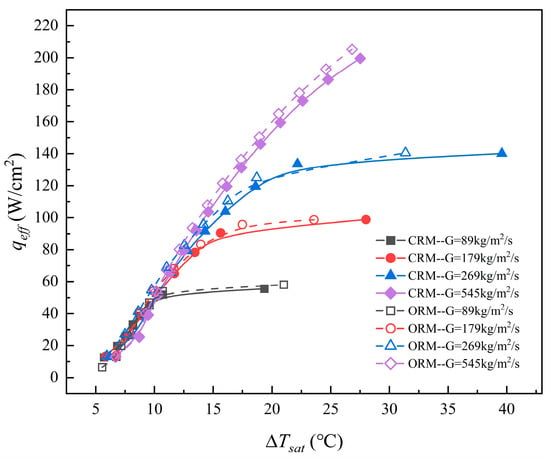
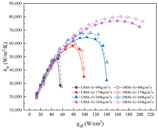
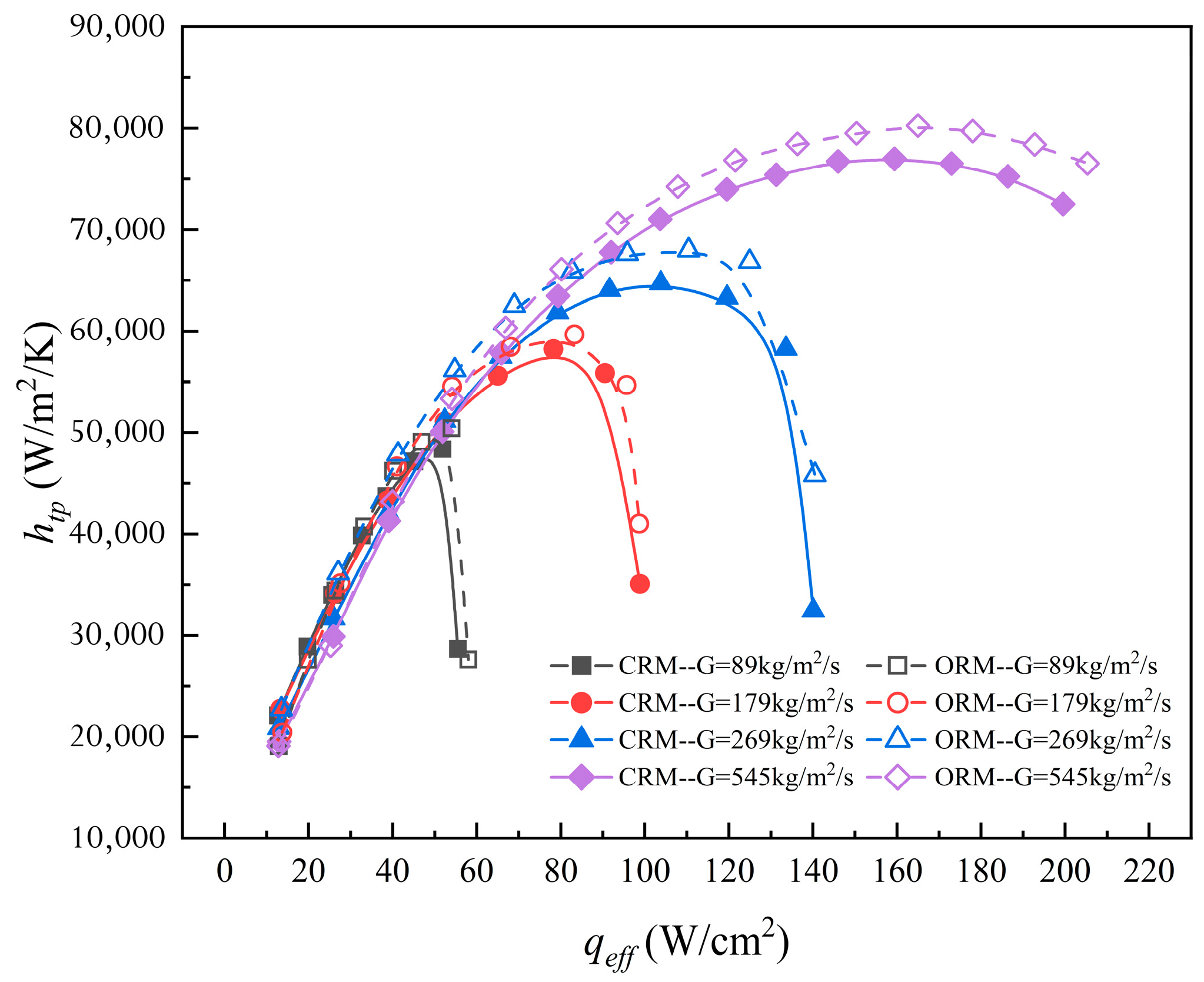
Figure 6 and Figure 7 illustrate the boiling heat transfer characteristics in microchannels under various mass fluxes. As shown in Figure 7, the two-phase heat transfer coefficient initially increases and subsequently decreases with increasing heat flux. At low heat fluxes, bubbly flow and plug flow dominate the flow regime, and nucleate boiling is the primary heat transfer mechanism. As the heat flux increases, interactions between bubbles and the liquid phase intensify, enhancing disturbances at the heated wall. This interaction reduces the thickness of the liquid film and improves heat removal. Consequently, convective boiling gradually becomes the dominant heat transfer mode, replacing nucleate boiling. Within the low mass flux range of 89–269 kg/m2·s, the ORM exhibits a 4.2–14.1% enhancement in the heat transfer coefficient while simultaneously achieving an 11.5–58.6% reduction in system pressure drop, compared with the CRM. This improvement can be attributed to the presence of the top-gap region in the ORM, which facilitates faster bubble detachment from the heated surface. Vapor bubbles preferentially accumulate in the top gap, promoting more effective liquid rewetting of the heated wall and thereby enhancing overall heat transfer performance. However, as the heat flux continues to increase, bubble coalescence becomes more pronounced. When the liquid is unable to rewet the heated surface in a timely manner, local dryout occurs. Further increases in heat flux lead to the formation of vapor films in these regions, ultimately resulting in thermal failure. As indicated in Figure 7, the differences in two-phase heat transfer coefficients between the open and closed microchannels are primarily governed by their respective rewetting capabilities. Owing to the enhanced rewetting enabled by the top gap, the ORM maintains superior heat transfer performance over a wider range of heat fluxes than the CRM.
Figure 6.
Boiling curves for ORM and CRM.
Figure 7.
Two-phase heat transfer coefficients’ variation as a function of heat flux for ORM and CRM.
In order to better analyze the effect of bubble content on heat transfer characteristics in microchannels, vapor quality and void rate were introduced. Xu and Fang [49] systematically evaluated the adaptability of the void fraction model to the two-phase flow of the refrigerants. The void fraction model proposed by Steiner [50] has an MAD of less than 6% when predicted in both horizontal flow and boiling process, which meets the requirements of this study. Steiner’s model is shown below:
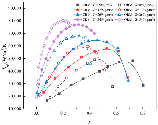
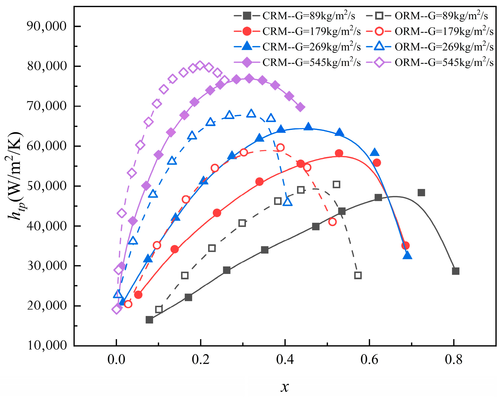
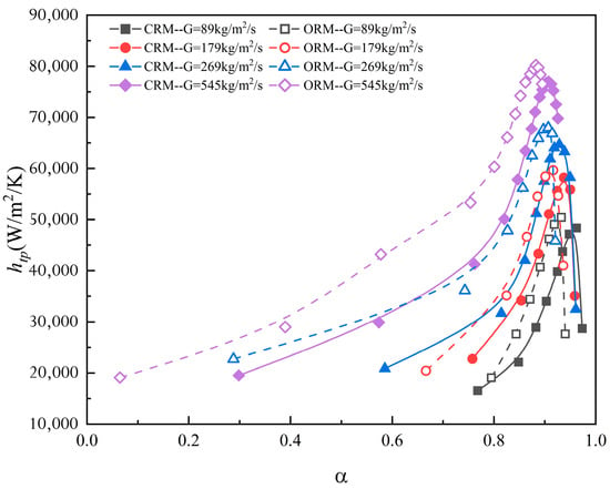
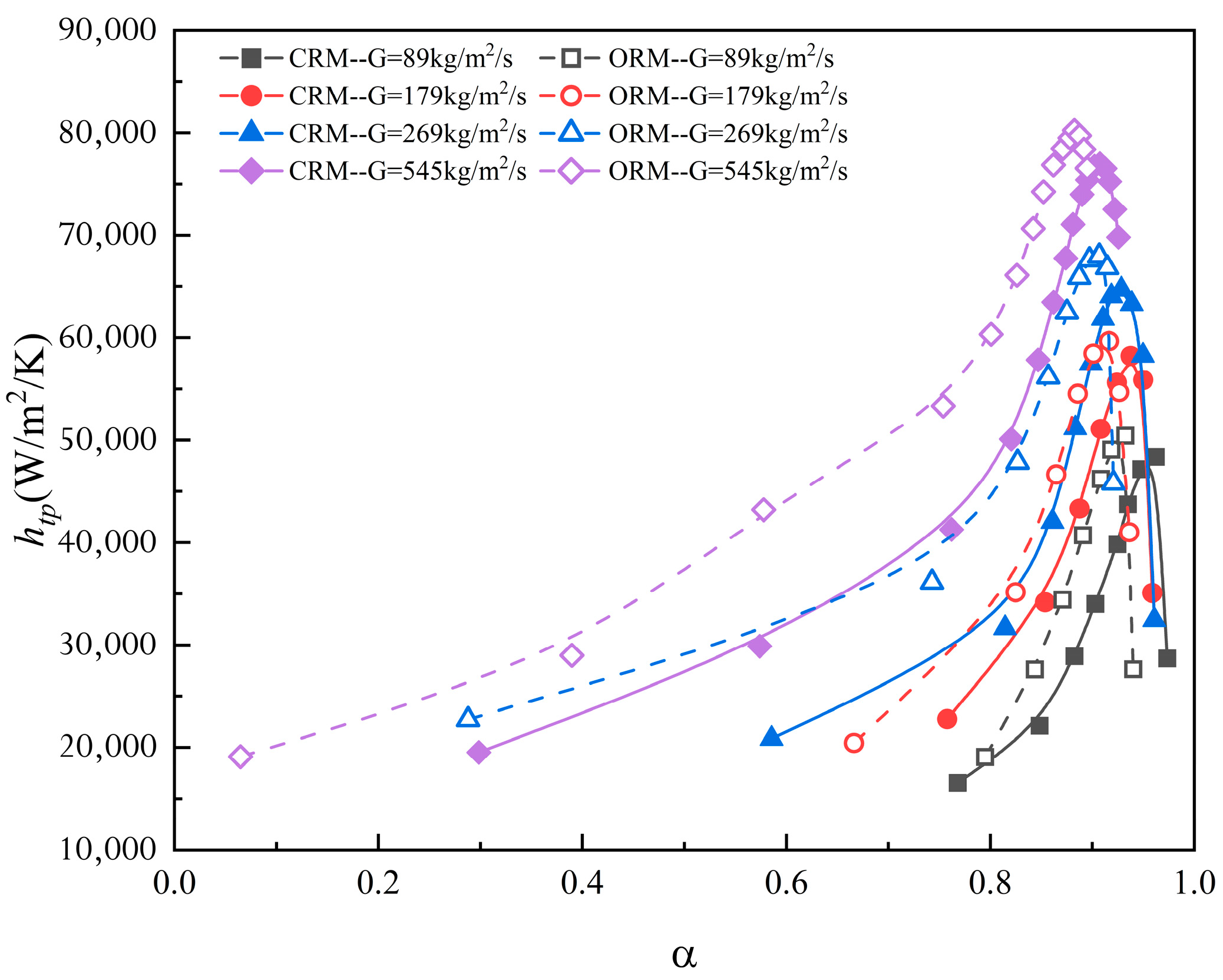
Figure 8 illustrates the variation in the two-phase heat transfer coefficient in microchannels as a function of vapor quality. The heat transfer coefficient initially increases with increasing vapor quality and then decreases beyond a certain point. An increase in mass flux further enhances the two-phase heat transfer coefficient across the vapor quality range. Due to the larger cross-sectional area of the ORM, the mass flow rate is higher than that in the CRM under the same mass flux. Consequently, under identical heat flux conditions, more liquid is available to rewet the heated surface, delaying the onset of local dryout. This contributes to the higher two-phase heat transfer coefficients observed in the open microchannel, as shown in Figure 7. Prior to reaching the peak two-phase heat transfer coefficient, the ORM exhibits both higher heat flux dissipation and a greater heat transfer coefficient under the same vapor quality conditions. The flow visualization in Figure 4 and Figure 5 further supports this, showing that with an increasing void fraction, the two-phase heat transfer coefficient follows a rising-then-falling trend, reaching a distinct maximum. Higher mass flux not only enhances the heat transfer coefficient but also causes this maximum to occur at a lower void fraction. As shown in Figure 9, the vapor phase occupies more than 80% of the microchannel volume at higher heat fluxes. Flow pattern analysis corresponding to the void fraction at maximum heat transfer based on Figure 4 and Figure 5 reveals that the dominant flow regime in the open microchannel is stratified flow, whereas in the closed microchannel, it is churn flow. Once the maximum heat transfer coefficient is reached, further increases in heat flux lead to higher void fraction, a rapid decline in the heat transfer coefficient, and the inability of the liquid to effectively rewet locally dried regions. This results in localized dryout, degraded heat transfer performance, and ultimately aligns with the flow pattern-based heat transfer analysis presented earlier.
Figure 8.
Two-phase heat transfer coefficients as a function of outlet vapor quality for ORM and CRM.
Figure 9.
Two-phase heat transfer coefficients’ variation as a function of void fraction for ORM and CRM.
4.3. Pressure Drop
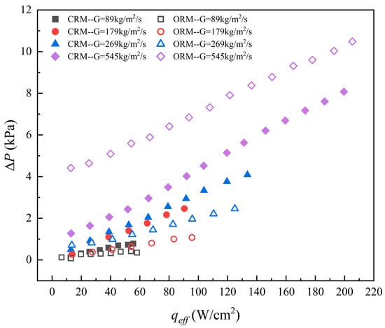
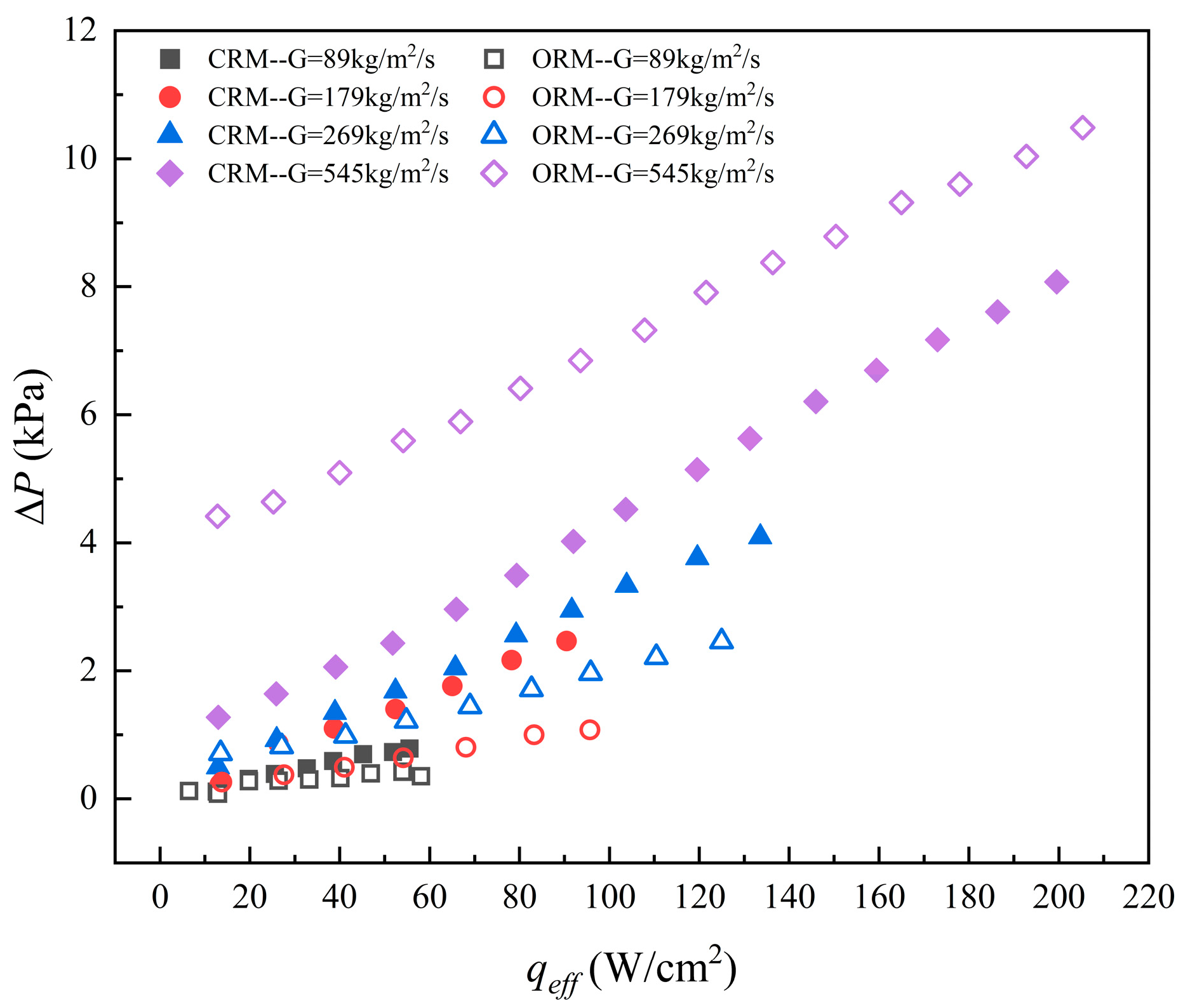
Figure 10 illustrates the relationship between heat flux and the pressure drop across the inlet and outlet of two types of rectangular microchannels. As the heat flux increases, the pressure drop exhibits an upward trend. Under identical heat flux conditions, a comparison of the two microchannel configurations reveals that when the mass flux is below 545 kg/m2·s, the pressure drop in the ORM is 11.5% to 58.6% lower than that in the CRM configuration. However, at a mass flux of 545 kg/m2·s, the pressure drop in the ORM exceeds that of the CRM by 29.9–246.8%, indicating a reversal of the pressure drop advantage at high mass flux. As shown by the stratified flow patterns in Figure 5 and supported by the analysis in Figure 11 [38], the top-gap structure in the ORM provides additional space for bubble expansion. At low mass flux, this structure effectively mitigates vapor-induced blockage and suppresses pressure drop growth. Moreover, the interconnection between adjacent microchannels through the top gap enables the pressure-driven redistribution of vapor and liquid, leading to a more stable pressure drop response. At high mass flux, however, although the top gap offers additional flow space, it also increases the contact area between the two-phase flow and the channel walls and introduces additional frictional resistance. As a result, the pressure drop in the ORM increases significantly and exceeds that of the CRM. These results indicate that flow boiling within the top-gap region plays a critical role in pressure drop variation and should not be neglected.
Figure 10.
Two-phase pressure drop variation as a function of heat flux for ORM and CRM.
Figure 11.
Schematic diagram of (a) type-I stratified flow and (b) type-II stratified flow [38].
4.4. Impact of Gravity and Inertia
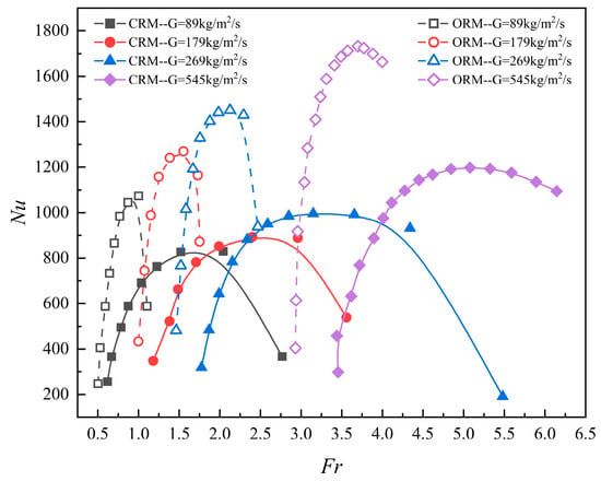
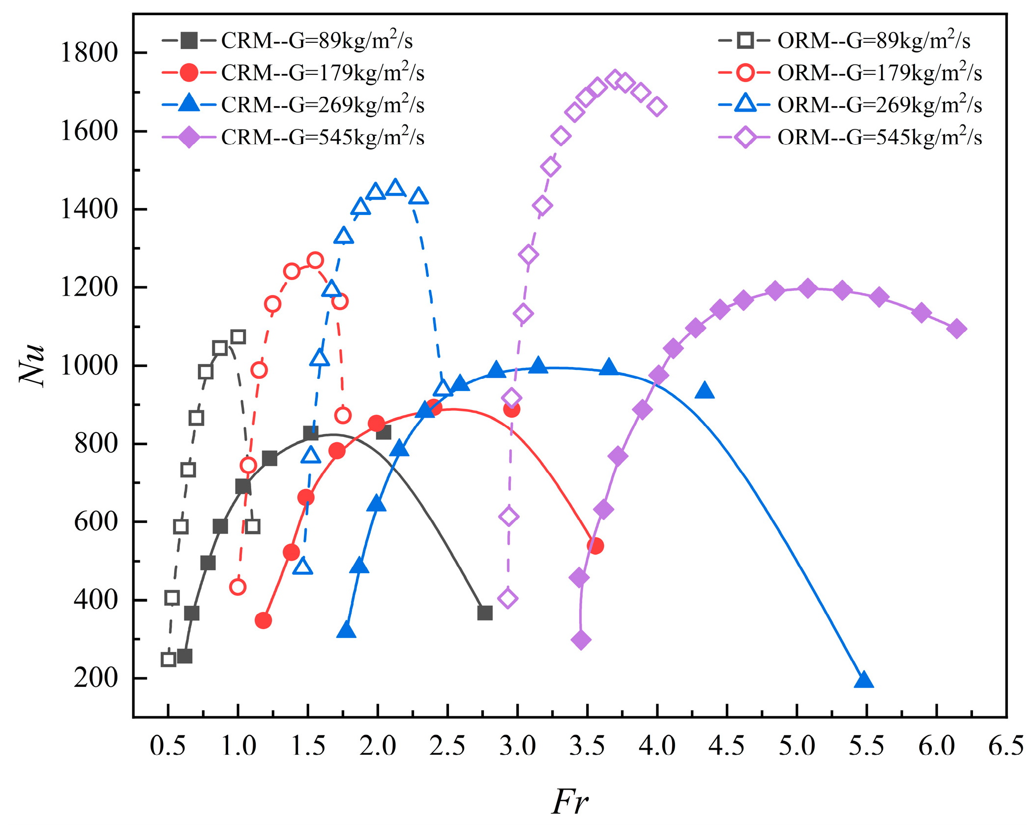
As the aspect ratio increases, the influence of gravity in the vertical direction on the fluid becomes more significant. To more accurately characterize the effects of gravity and inertial forces on heat transfer in microchannels, the Froude number (Fr) and Nusselt number (Nu) are introduced for analysis. The definition of the Froude number is as follows:
is the flow velocity, is the gravitational acceleration, and is the characteristic length. The formula for calculating is as follows:
and represent the gas and liquid densities under the evaporation pressure in the microchannel, respectively, and denotes the cross-sectional area of the microchannel. Figure 12 illustrates the relationship between the Nu and the Fr within the microchannel. As the Fr increases, the Nu first increases and then decreases. With an increase in mass flux, the maximum Nu also increases, and the inertial forces gradually dominate. For the same mass flux, the response of the Nu to changes in the Fr is more pronounced in the ORM compared to the CRM. This is because the top-gap structure in the ORM provides greater vertical motion space for the working fluid, extending the effect of gravity, while also connecting the channels, allowing the forces within each channel to influence each other. As the heat flux increases, the Fr exceeds 1, and inertial forces begin to dominate, weakening the influence of gravity. However, at a low mass flux of 89 kg/m2·s, the Fr in the ORM remains between 0 and 1, and the influence of gravity on heat transfer cannot be ignored. Meanwhile, in the CRM, the Fr shifts from 0 to 1 to 1 to 3, with the dominant force transitioning from gravity to inertial force, which also leads to significant pressure and temperature fluctuations in the CRM, as shown in Figure 13 and Figure 14.
Figure 12.
Variation in Nusselt number as a function of Froude number with varying mass flux.
Figure 13.
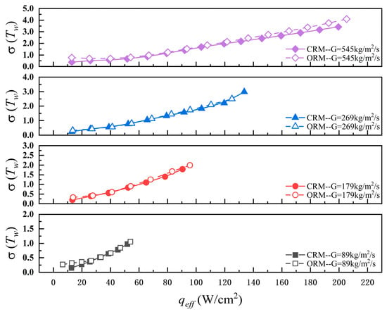
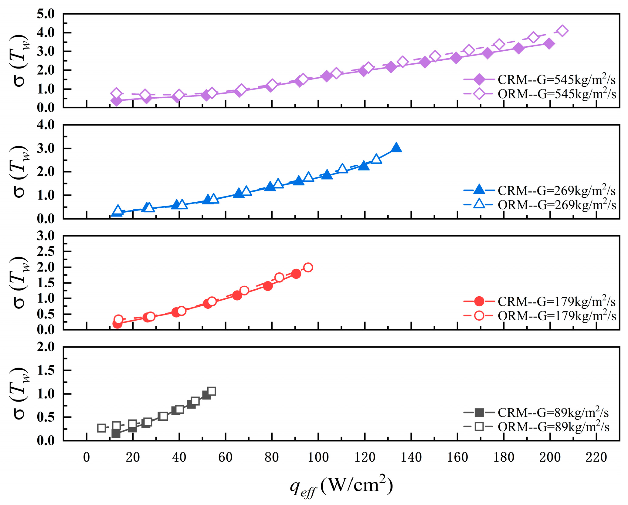
Fluctuation degree of bottom wall temperature for ORM and CRM with effective heat flux.
Figure 14.
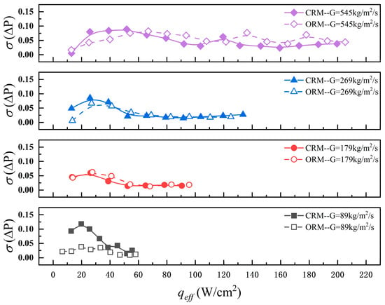
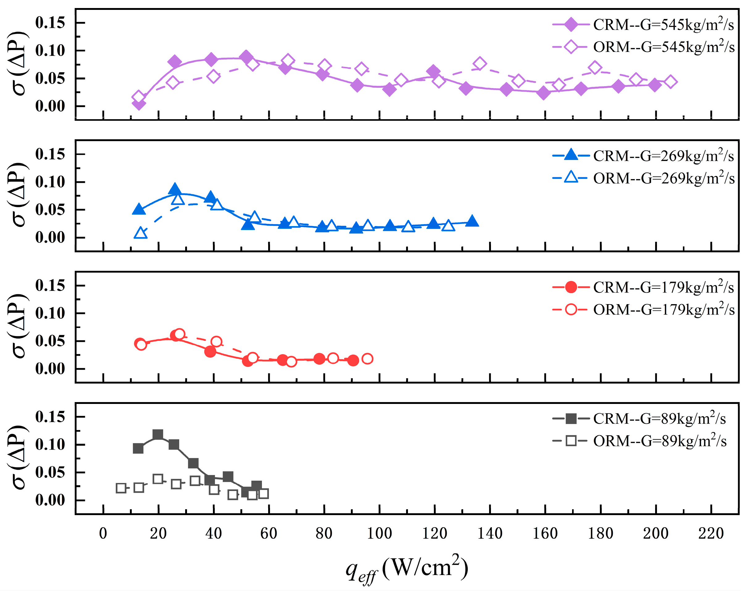
Fluctuation degree of pressure drop for ORM and CRM with effective heat flux.
4.5. Instabilities
Instability is an important factor characterizing microchannel flow boiling. In order to analyze the two-phase boiling instability of two microchannel structures, the standard deviation of and was introduced to quantify the fluctuation stability [40]. The calculation is as follows:
Figure 13 illustrates the relationship between the standard deviation of wall temperature and heat flux. As the heat flux increases, the standard deviation of wall temperature increases monotonically. This trend is mainly attributed to the progressive intensification of boiling within the microchannel. With increasing heat flux, bubble nucleation, growth, coalescence, and breakup become more frequent, leading to stronger interactions between bubbles and the heated wall. The repeated processes of bubble impingement on the wall and subsequent liquid rewetting induce localized and transient temperature fluctuations, which intensify at higher heat fluxes, resulting in a continuous increase in wall temperature standard deviation. In addition, increasing the mass flux leads to a further increase in wall temperature standard deviation. At higher mass fluxes, the stronger liquid inertia delays the onset of boiling (ONB), causing boiling to initiate further downstream along the microchannel. Consequently, boiling cannot effectively cover the entire heated surface, and single-phase convection coexists with localized boiling regions. This non-uniform distribution of boiling activity results in an increasingly uneven wall temperature distribution, thereby increasing the standard deviation of wall temperature. At low heat flux, the standard deviation of wall temperature in the ORM is smaller than that in the CRM. As shown in Figure 4, at low heat flux, the flow pattern in the ORM is primarily slug flow, and the impact of bubbles on the wall temperature is relatively small. Figure 14 shows the variation in the standard deviation of pressure drop at the inlet and outlet of the microchannel with heat flux density. The standard deviation of pressure drop initially increases and then decreases with rising heat flux, eventually stabilizing. With an increase in mass flux, the maximum standard deviation of pressure drop also increases. In the CRM, due to the transition of dominant forces from gravity to inertial forces at low mass flux, the flow regime changes from nucleate boiling to convective boiling, resulting in significantly higher pressure drop fluctuations compared to the ORM. As seen in Figure 4 and Figure 5, when the flow pattern within the channel evolves into slug flow, the standard deviation of pressure drop reaches its maximum value. The top-gap structure in the ORM provides additional space for bubble expansion and creates new pathways for bubbles to enter other channels, effectively mitigating the pressure fluctuations caused by bubble growth. As a result, the standard deviation of pressure drop in the ORM increases more gradually with heat flux compared to the CRM.
4.6. Comprehensive Performance Analysis
The previous sections have thoroughly discussed the flow pattern variations, heat transfer characteristics, and pressure drop behaviors in large-aspect-ratio rectangular microchannels. Although the ORM demonstrates superior heat transfer and pressure drop performance under certain conditions, a comprehensive evaluation of the overall performance of both ORM and CRM is carried out by introducing the figure of merit (FOM) [51,52,53]. The FOM is calculated by the following formula:
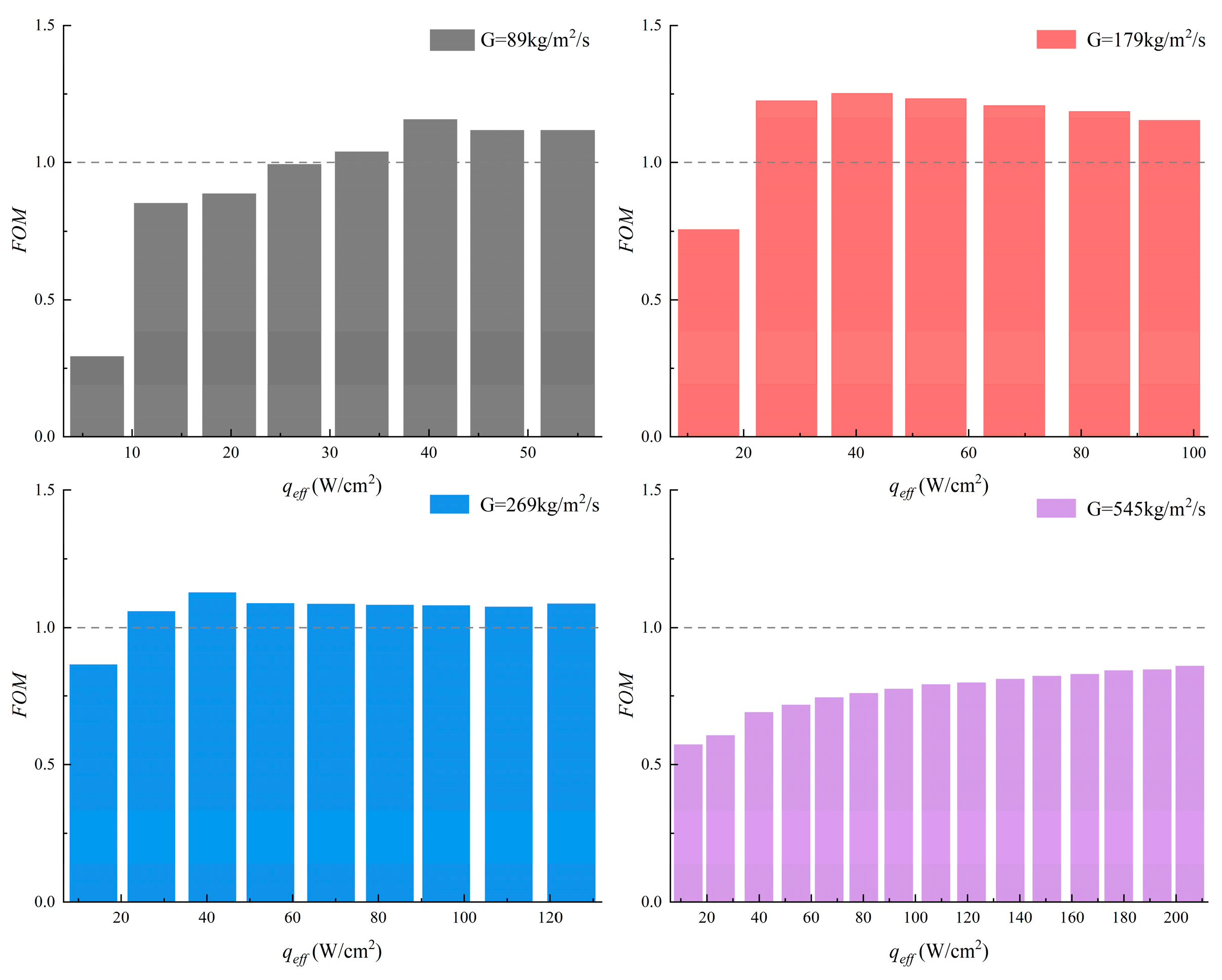
represents the pump power, and denotes the mass flow rate. The subscripts O and C refer to the open and closed rectangular microchannels, respectively. When the FOM is greater than 1, the ORM exhibits superior overall performance compared to the CRM; when FOM is less than 1, its performance is inferior. Figure 15 illustrates the variation in FOM with heat flux under different mass flux conditions. At mass flux values between 89 and 269 kg/m2·s, most FOM values exceed 1, indicating better heat transfer performance for the ORM. The top-gap structure provides additional space for bubble growth, reducing pump power consumption and enhancing the heat transfer coefficient at high heat flux. However, at a mass flux of 545 kg/m2·s, the FOM drops below 1. As shown in Figure 7 and Figure 10, although the heat transfer coefficient of the ORM is higher than that of the CRM, the frictional pressure drop increases significantly, leading to higher pump power consumption and reduced overall performance. Therefore, the additional pressure drop loss due to the top-gap structure should be considered at high mass fluxes to ensure that the ORM achieves optimal performance.
Figure 15.
The variation in FOM as a function of effective heat flux at different mass flux.
5. Conclusions
The flow boiling heat transfer characteristics of R245fa in an ORM with a large aspect ratio were investigated and compared with those in a CRM. The experiments were carried out at a mass flux of 89 to 545 kg/m2·s, heat fluxes of 6.3 to 218.5 W/cm2, and an inlet temperature of 14 °C. Flow pattern transition, flow boiling heat transfer characteristics, pressure drop, instability, and overall performance were analyzed. The study reached the following main conclusions:
- Flow boiling in large-aspect-ratio rectangular microchannels exhibits bubbly, slug, and churn flows in the CRM, while the ORM additionally shows stratified flow, with earlier flow pattern transitions, easier slug flow patterns, and more pronounced inlet bubble counterflow compared to the CRM.
- The ORM enhances the two-phase heat transfer coefficient by 4.2–14.1% relative to the CRM over the tested mass flux range of 89 to 545 kg/m2·s. Regarding pressure drop, the ORM reduces it by 11.5–58.6% compared to the CRM at lower mass fluxes (≤269 kg/m2·s); however, at higher mass fluxes (545 kg/m2·s), the pressure drop increases by 29.9–246.8% due to intensified two-phase friction within the gap region.
- In large-aspect-ratio microchannels, gravity effects dominate the flow behavior in the ORM at the lowest tested mass flux of 89 kg/m2·s, whereas inertial forces gradually become dominant in the CRM as heat flux increases. At mass fluxes of 179 kg/m2·s and above, inertial force controls the boiling process in both of these structures.
- The ORM exhibits higher wall temperature and pressure drop stability under low mass flux (≤269 kg/m2·s), and the FOM is superior to that of the CRM. However, when the mass flux reaches 545 kg/m2·s, the top gap will be filled with two-phase fluid, resulting in increased pressure drop and intensified thermal-fluid oscillations compared to the CRM.
Overall, this study clarifies the coupled effects of gap structures and large aspect ratios on flow boiling behavior, heat transfer enhancement, and pressure drop sensitivity, providing guidance for the design and optimization of high-performance open microchannels. However, due to the lack of quantitative investigation into the effect of top-gap dimensions in open microchannels, the validity of the present findings cannot be guaranteed under different flow conditions or geometric scales.
Author Contributions
Conceptualization, Y.G. and L.L.; methodology, Y.G. and L.L.; software, Y.G.; validation, Y.G., L.L., X.G. and N.W.; formal analysis, Y.G.; investigation, Y.G., X.G. and N.W.; resources, B.Z.; data curation, Y.G. and L.L.; writing—original draft preparation, Y.G.; writing—review and editing, Y.G. and B.Z.; visualization, Y.G.; supervision, B.Z., X.G. and N.W.; project administration, B.Z.; funding acquisition, B.Z. All authors have read and agreed to the published version of the manuscript.
Funding
This research received no external funding.
Data Availability Statement
The data supporting the findings of this study are available from the corresponding author upon reasonable request.
Conflicts of Interest
The authors declare no conflict of interest.
Abbreviations
| cross-sectional area of the reduced copper block (m2) | inlet liquid temperatures (K) | ||
| cross-sectional area of fluid flow (m2) | flow rates (m/s) | ||
| footprint area of the microchannels (m2) | width of the heat sink (mm) | ||
| CRM | closed rectangular microchannel | width of the fin (mm) | |
| CHF | critical heat flux (W/cm2) | width of the microchannel (mm) | |
| specific heat of the liquid (J/kg K) | outlet vapor quality | ||
| hydraulic diameter (m) | distance from thermocouple to surface (mm) | ||
| FOM | figure of merit | vertical thermocouple spacing (mm) | |
| FMC | first microchannel test section | ||
| Fr | Froude number (u/) | Greek symbols | |
| G | mass flux (kg/m2 s) | thermal conductivity (W/m k) | |
| gravitational acceleration (m/s2) | liquid density (kg/m3) | ||
| two-phase heat transfer coefficient (W/m2 K) | gas density (kg/m3) | ||
| latent heat of the liquid (J/kg) | surface tension (N/m) | ||
| height of the gap (mm) | void fraction | ||
| height of the microchannel (mm) | distance (m) | ||
| thermal conductivity (W/m k) | |||
| length of the heat sink (mm) | Subscripts | ||
| mass flow rate (kg/s) | c | contraction | |
| Nu | Nussle number (htp d/λ) | ch | channel |
| ORM | open rectangular microchannel | cu | copper |
| outlet expansion pressure drop (kPa) | e | expansion | |
| two-phase pressure drop (kPa) | eff | effective | |
| wall superheat (°C) | f | fin | |
| total pressure drop of evaporator (kPa) | fl | fluid | |
| inlet contraction pressure drop (kPa) | g | gap | |
| pumping power | in | inlet | |
| effective heat load (W) | l | liquid | |
| q | heat flux (W/cm2) | sat | saturation |
| effective heat flux (W/cm2) | tp | two-phase | |
| R2 | coefficients of determination | w | wall |
| saturation temperature (K) | g | gas | |
| wall temperature (K) | |||
References
- Kadam, S.T.; Kumar, R. Twenty first century cooling solution: Microchannel heat sinks. Int. J. Therm. Sci. 2014, 85, 73–92. [Google Scholar] [CrossRef] [Scilit]
- He, Z.; Yan, Y.; Zhang, Z. Thermal management and temperature uniformity enhancement of electronic devices by micro heat sinks: A review. Energy 2021, 216, 119223. [Google Scholar] [CrossRef] [Scilit]
- Kandlikar, S.G. Review and Projections of Integrated Cooling Systems for Three-Dimensional Integrated Circuits. J. Electron. Packag. 2014, 136, 024001. [Google Scholar] [CrossRef] [Scilit]
- Herwig, H. High Heat Flux Cooling of Electronics: The Need for a Paradigm Shift. J. Heat Transf. 2013, 135, 111013. [Google Scholar] [CrossRef] [Scilit]
- Tuckerman, D.B.; Pease, R.F.W. High-Performance Heat Sinking for VLSI. IEEE Electron. Device Lett. 1981, 2, 126–129. [Google Scholar] [CrossRef] [Scilit]
- Deng, D.; Zeng, L.; Sun, W. A review on flow boiling enhancement and fabrication of enhanced microchannels of microchannel heat sinks. Int. J. Heat Mass Transf. 2021, 175, 121332. [Google Scholar] [CrossRef] [Scilit]
- Ma, A.; Wei, J.; Yuan, M.; Fang, J. Enhanced flow boiling heat transfer of FC-72 on micro-pin-finned surfaces. Int. J. Heat Mass Transf. 2009, 52, 2925–2931. [Google Scholar]
- McNeil, D.; Raeisi, A.; Kew, P.; Bobbili, P. A comparison of flow boiling heat-transfer in in-line mini pin fin and plane channel flows. Appl. Therm. Eng. 2010, 30, 2412–2425. [Google Scholar] [CrossRef] [Scilit]
- Law, M.; Lee, P.-S. A comparative study of experimental flow boiling heat transfer and pressure characteristics in straight- and oblique-finned microchannels. International J. Heat Mass Transf. 2015, 85, 797–810. [Google Scholar] [CrossRef] [Scilit]
- Prajapati, Y.K.; Pathak, M.; Khan, M.K. A comparative study of flow boiling heat transfer in three different configurations of microchannels. Int. J. Heat Mass Transf. 2015, 85, 711–722. [Google Scholar] [CrossRef] [Scilit]
- Krishnamurthy, S.; Peles, Y. Flow boiling of water in a circular staggered micro-pin fin heat sink. Int. J. Heat Mass Transf. 2008, 51, 1349–1364. [Google Scholar] [CrossRef] [Scilit]
- Wan, W.; Deng, D.; Huang, Q.; Zeng, T.; Huang, Y. Experimental study and optimization of pin fin shapes in flow boiling of micro pin fin heat sinks. Appl. Therm. Eng. 2017, 114, 436–449. [Google Scholar] [CrossRef] [Scilit]
- Woodcock, C.; Yu, X.; Plawsky, J.; Peles, Y. Piranha Pin Fin (PPF)—Advanced flow boiling microstructures with low surface tension dielectric fluids. Int. J. Heat Mass Transf. 2015, 90, 591–604. [Google Scholar] [CrossRef] [Scilit]
- Yu, X.; Woodcock, C.; Wang, Y.; Plawsky, J.; Peles, Y. A Comparative Study of Flow Boiling in a Microchannel with Piranha Pin Fins. J. Heat Transf. 2016, 5, 111501–111502. [Google Scholar] [CrossRef] [Scilit]
- Jiang, L.; Koo, J.-M.; Wang, E.; Bari, A.; Cho, E.S.; Ong, W.; Prasher, R.S.; Maveety, J.; Kim, M.S.; Kenny, T.W.; et al. Cross-Linked Microchannels for VLSI Hotspot Cooling. In Proceedings of the International Mechanical Engineering Congress and Exposition, New Orleans, LA, USA, 17–22 November 2002. [Google Scholar]
- Xu, J.; Gan, Y.; Zhang, D.; Li, X. Microscale heat transfer enhancement using thermal boundary layer redeveloping concept. Int. J. Heat Mass Transf. 2005, 48, 1662–1674. [Google Scholar] [CrossRef] [Scilit]
- Fu, B.-R.; Lee, C.-Y.; Pan, C. The effect of aspect ratio on flow boiling heat transfer of HFE-7100 in a microchannel heat sink. Int. J. Heat Mass Transf. 2013, 58, 53–61. [Google Scholar] [CrossRef] [Scilit]
- Markal, B.; Aydin, O.; Avci, M. Effect of aspect ratio on saturated flow boiling in microchannels. Int. J. Heat Mass Transf. 2016, 93, 130–143. [Google Scholar] [CrossRef] [Scilit]
- Yin, L.; Xu, R.; Jiang, P.; Cai, H.; Jia, L. Subcooled flow boiling of water in a large aspect ratio microchannel. Int. J. Heat Mass Transf. 2017, 112, 1081–1089. [Google Scholar] [CrossRef] [Scilit]
- Cui, P.; Liu, Z. Experimental study on flow boiling in ultrahigh-aspect-ratio copper microchannel heat sink. Appl. Therm. Eng. 2023, 223, 119975. [Google Scholar] [CrossRef] [Scilit]
- Drummond, K.P.; Weibel, J.A.; Garimella, S.V. Two-phase flow morphology and local wall temperatures in high-aspect-ratio manifold microchannels. Int. J. Heat Mass Transf. 2020, 153, 119551. [Google Scholar] [CrossRef] [Scilit]
- Cheng, X.; Wu, H. Improved flow boiling performance in high-aspect-ratio interconnected microchannels. Int. J. Heat Mass Transf. 2021, 165, 120627. [Google Scholar] [CrossRef] [Scilit]
- Cheng, X.; Wu, H. Enhanced flow boiling performance in high-aspect-ratio groove-wall microchannels. Int. J. Heat Mass Transf. 2021, 164, 120468. [Google Scholar] [CrossRef] [Scilit]
- Zhang, Y.; Fan, W.; Zhang, Z.; Li, J.; Zhai, T.; Liu, W.; Liu, Z. Developing a stable microchannel flow boiling heat sink with a venting membrane. Int. Commun. Heat Mass Transf. 2024, 158, 107896. [Google Scholar] [CrossRef] [Scilit]
- Priy, A.; Eqbal, D.; Pathak, M.; Khan, M. Suppression of flow boiling instabilities in microchannel heat sinks using a passive vapor venting technique. Therm. Sci. Eng. Prog. 2025, 65, 103909. [Google Scholar] [CrossRef] [Scilit]
- Cooke, D.; Kandlikar, S.G. Pool Boiling Heat Transfer and Bubble Dynamics Over Plain and Enhanced Microchannels. In Proceedings of the 8th International Conference on Nanochannels, Microchannels, and Minichannels collocated with 3rd Joint US-European Fluids Engineering Summer Meeting, Montreal, QC, Canada, 1–5 August 2010. [Google Scholar]
- Kandlikar, S.G.; Widger, T.; Kalani, A.; Mejia, V. Enhanced Flow Boiling Over Open Microchannels with Uniform and Tapered Gap Manifolds. J. Heat Transf. 2013, 135, 061401. [Google Scholar] [CrossRef] [Scilit]
- Kalani, A.; Kandlikar, S.G. Effect of taper on pressure recovery during flow boiling in open microchannels with manifold using homogeneous flow model. Int. J. Heat Mass Transf. 2015, 83, 109–117. [Google Scholar] [CrossRef] [Scilit]
- Kalani, A.; Kandlikar, S.G. Flow patterns and heat transfer mechanisms during flow boiling over open microchannels in tapered manifold (OMM). Int. J. Heat Mass Transf. 2015, 89, 494–504. [Google Scholar] [CrossRef] [Scilit]
- Kalani, A.; Kandlikar, S.G. Evaluation of Pressure Drop Performance During Enhanced Flow Boiling in Open Microchannels with Tapered Manifolds. J. Heat Transf. 2014, 136, 051502. [Google Scholar] [CrossRef] [Scilit]
- Balasubramanian, K.; Krishnan, R.A.; Suresh, S. Spatial orientation effects on flow boiling performances in open microchannels heat sink configuration under a wide range of mass fluxes. Exp. Therm. Fluid Sci. 2018, 99, 392–406. [Google Scholar] [CrossRef] [Scilit]
- Recinella, A.; Kandlikar, S.G. Enhanced Flow Boiling Using Radial Open Microchannels with Manifold and Offset Strip Fins. J. Heat Transf. 2018, 140, 021502. [Google Scholar] [CrossRef] [Scilit]
- Kadam, S.T.; Kumar, R.; Abiev, R. Performance Augmentation of Single-Phase Heat Transfer in Open-Type Microchannel Heat Sink. J. Thermophys. Heat Transf. 2019, 33, 416–424. [Google Scholar] [CrossRef] [Scilit]
- Xia, G.; Cheng, Y.; Cheng, L.; Li, Y. Heat Transfer Characteristics and Flow Visualization during Flow Boiling of Acetone in Semi-Open Multi-Microchannels. Heat Transf. Eng. 2019, 40, 1349–1362. [Google Scholar] [CrossRef] [Scilit]
- Zhao, Q.; Qiu, J.; Zhou, J.; Lu, M.; Li, Q.; Chen, X. Visualization study of flow boiling characteristics in open microchannels with different wettability. Int. J. Heat Mass Transf. 2021, 180, 121808. [Google Scholar] [CrossRef] [Scilit]
- Bhandari, P.; Prajapati, Y.K. Thermal performance of open microchannel heat sink with variable pin fin height. Int. J. Therm. Sci. 2021, 159, 106609. [Google Scholar] [CrossRef] [Scilit]
- Yin, L.; Jiang, P.; Xu, R.; Hu, H.; Jia, L. Heat transfer and pressure drop characteristics of water flow boiling in open microchannels. Int. J. Heat Mass Transf. 2019, 137, 204–215. [Google Scholar] [CrossRef] [Scilit]
- Yin, L.; Jiang, P.; Xu, R.; Wang, W.; Jia, L. Visualization of flow patterns and bubble behavior during flow boiling in open microchannels. Int. Commun. Heat Mass Transf. 2017, 85, 131–138. [Google Scholar] [CrossRef] [Scilit]
- Qiu, J.; Zhao, Q.; Lu, M.; Zhou, J.; Hu, D.; Qin, H.; Chen, X. Experimental study of flow boiling heat transfer and pressure drop in stepped oblique-finned microchannel heat sink. Case Stud. Therm. Eng. 2022, 30, 101745. [Google Scholar] [CrossRef] [Scilit]
- Zhao, Q.; Zhou, J.; Lu, M.; Liu, C.; Zhang, D.; Li, Q.; Chen, X. Irregular-shaped nucleated bubbles induced enhancement of subcooled flow boiling heat transfer in leaf vein inspired three-tiered open microchannels (LTOMCs). Int. J. Heat Mass Transf. 2023, 211, 124281. [Google Scholar] [CrossRef] [Scilit]
- Kaniowski, R.; Pastuszko, R. Boiling of FC-72 on Surfaces with Open Copper Microchannel. Energies 2021, 14, 7283. [Google Scholar] [CrossRef] [Scilit]
- Dong, Y.; Yu, Y.; Ibrahim, A.; Hu, X.; Hao, Y. Influence of liquid height on pool boiling heat transfer over open rectangular microchannels. Appl. Therm. Eng. 2023, 228, 120453. [Google Scholar] [CrossRef] [Scilit]
- Zhao, Q.; Zhang, D.; Qiu, J.; Lu, M.; Zhou, J.; Chen, X. Bubble behaviors and flow boiling characteristics in open microchannels with large aspect ratio. Appl. Therm. Eng. 2022, 213, 118768. [Google Scholar] [CrossRef] [Scilit]
- Alam, T.; Lee, P.S.; Yap, C.R.; Jin, L. Experimental investigation of local flow boiling heat transfer and pressure drop characteristics in microgap channel. Int. J. Multiph. Flow 2012, 42, 164–174. [Google Scholar] [CrossRef] [Scilit]
- Moffat, R.J. Describing the Uncertainties in Experimental Results. Exp. Therm. Fluid Sci. 1988, 1, 3–17. [Google Scholar] [CrossRef] [Scilit]
- Guo, Y.; Li, L.; Zhang, B.; Guo, X. Numerical study of bubble growth and flow boiling characteristics in open microchannels with different gap height. Appl. Therm. Eng. 2025, 265, 125567. [Google Scholar] [CrossRef] [Scilit]
- Lin, Y.; Luo, Y.; Li, W.; Li, J.; Sun, Z.; Cao, Y.; Minkowycz, W. Numerical study of flow reversal during bubble growth and confinement of flow boiling in microchannels. Int. J. Heat Mass Transf. 2021, 177, 121491. [Google Scholar] [CrossRef] [Scilit]
- Hedau, G.; Dey, P.; Raj, R.; Saha, S.K. Experimental and numerical investigation of the effect of number of parallel microchannels on flow boiling heat transfer. Int. J. Heat Mass Transf. 2020, 158, 119973. [Google Scholar] [CrossRef] [Scilit]
- Xu, Y.; Fang, X. Correlations of void fraction for two-phase refrigerant flow in pipes. Appl. Therm. Eng. 2014, 64, 242–251. [Google Scholar] [CrossRef] [Scilit]
- VDI Heat Atlas. Heat Transfer to Boiling Saturated Liquids; VDI-Warmeatlas (VDI Heat Atlas): Düsseldorf, Germany, 1993. [Google Scholar]
- Yadav, V.; Baghel, K.; Kumar, R.; Kadam, S. Numerical investigation of heat transfer in extended surface microchannels. Int. J. Heat Mass Transf. 2016, 93, 612–622. [Google Scholar] [CrossRef] [Scilit]
- Zhao, J.; Huang, S.; Gong, L.; Huang, Z. Numerical study and optimizing on micro square pin-fin heat sink for electronic cooling. Appl. Therm. Eng. 2016, 93, 1347–1359. [Google Scholar] [CrossRef] [Scilit]
- Zhou, J.; Li, Q.; Chen, X. Micro pin fins with topologically optimized configurations enhance flow boiling heat transfer in manifold microchannel heat sinks. Int. J. Heat Mass Transf. 2023, 206, 123956. [Google Scholar] [CrossRef] [Scilit]

Disclaimer/Publisher’s Note: The statements, opinions and data contained in all publications are solely those of the individual author(s) and contributor(s) and not of MDPI and/or the editor(s). MDPI and/or the editor(s) disclaim responsibility for any injury to people or property resulting from any ideas, methods, instructions or products referred to in the content. |
© 2026 by the authors. Licensee MDPI, Basel, Switzerland. This article is an open access article distributed under the terms and conditions of the Creative Commons Attribution (CC BY) license.