


Abstract
Input current ripple reduction in DC-DC boost converters is a persistent challenge because input current ripples are driving up filter requirements, electromagnetic interference (EMI), and stress on sources and loads. This ultimately limits power density and efficiency in many applications, from photovoltaic systems to fuel cells and electric vehicle powertrains. While classical interleaving and passive filtering approaches have been proposed, recent years have brought promising advances in magnetic coupling, higher switching frequency, novel interleaved topologies, and control-based reduction strategies. The current state of the art offers a solid foundation, and further investigations could help enable a more comprehensive comparison and better guide the selection of the most appropriate approach according to performance objectives. An increasing number of recent publications are focusing on the topic of current ripple reduction. Indeed, a recent analysis of international scientific databases shows a steady increase in publications addressing current ripple in DC-DC converters, reflecting both the intensifying demands of modern power electronics applications and the recognition that traditional solutions may not be the most suitable for next-generation converters and systems. This review fills that gap in the case of DC-DC boost converters, where the literature remains fragmented, and a unified comparison of these approaches is still lacking. It compiles, analyses, and compares all current techniques for reducing input current ripple, covering passive filter and inductor sizing methods, component-level improvements such as coupled inductors and wide-bandgap devices, interleaving-based converter architectures, closed-loop control strategies, and hybrid approaches that combine multiple techniques based on papers published over the last decade (2016–2026). More particularly, the dependence of LC filter sizing on the duty cycle and switching frequency is examined, mutual inductance design for ripple cancellation is explored, and the operation of destructive interference in parallel-phase and multilevel converter configurations is compared. The techniques reviewed in this paper highlight remarkable results: A 60–90% ripple reduction by using magnetic coupling at 50% duty cycle, near-zero input current ripple with multiphase interleaving in N-phase converters with optimal phase shift, and dynamic ripple suppression across wide operating ranges through advanced control. The review concludes with a qualitative comparison of the main input current ripple reduction technique families in terms of advantages, limitations, application domains, and reduction potential, and discusses opportunities for hybrid passive–active strategies in next-generation high-efficiency boost converters.
1. Introduction
Non-isolated DC-DC converters have become essential building blocks in modern power electronics, serving critical roles in renewable energy systems, electric vehicles (EVs), energy storage, and distributed power architectures. As power density requirements increase and efficiency standards tighten, Input Current Ripple (ICR) has emerged as a key design constraint that directly affects component sizing, electromagnetic interference (EMI), thermal management, and system reliability. While isolated topologies offer galvanic separation for specific applications [1,2], non-isolated converters, particularly boost converters, remain prevalent due to their simplicity, lower component count, reduced cost, and higher efficiency in applications where isolation is not mandatory. These characteristics make them particularly suitable in fuel cell (FC) systems [3], photovoltaic systems [4], battery management in EVs [5], and charging stations [6]. ICR, denoted , corresponds to the AC fluctuation presents in the DC, resulting from the converter’s switching action. It is defined in this work as , where and denote the maximum and minimum current values, respectively. It should be noted that some authors define the ripple as , which may lead to ambiguity [1]. In the case of a classical boost converter (Figure 1), the ICR is also the inductor current ripple, . It depends on the voltage applied across it, the transistor duty cycle D, the switching frequency (period ), and the inductance L.
Figure 1.
Electrical topology of a conventional boost converter.
The standard inductor current ripple expression for a conventional boost is:
Figure 2 illustrates the inductor current waveform for a boost converter.
Figure 2.
Input current waveform of a conventional boost converter.
This ripple appears both in the inductor and at the converter input/output terminals, with inductor current ripple typically designed within a range of 5% to 40% of the rated current [5]. This range reflects a fundamental trade-off: higher ripple reduces inductor size but increases losses, EMI, and filtering requirements, while lower ripple demands larger inductances at the cost of weight, volume, and potentially higher losses [7,8]. In a conventional boost converter, the inductor current ripple directly corresponds to the ICR. However, this property does not hold for all converter topologies and therefore requires further in-depth investigation. The impact of ICR extends beyond passive component sizing to affect source longevity and system efficiency. For example, FC stacks are particularly vulnerable to high-amplitude low-frequency ripple [9], whereas continuous high-frequency low-ripple current has less impact [3]. Moreover, ripple-induced losses reduce vehicle range in FC heavy-duty trucks [10], and battery systems in EVs experience accelerated degradation under excessive ripple conditions [3]. Furthermore, excessive ripple raises RMS current, which increases conduction losses in switches and inductors, and generates EMI that requires additional filtering to meet regulatory standards. Most boost converters operate in continuous conduction mode (CCM) to ensure predictable current waveforms and effective inductor current ripple control. CCM maintains a nonzero inductor current over the switching period but requires careful inductor sizing, making ripple analysis essential to prevent unintended transitions to discontinuous conduction mode (DCM) under light-load conditions.
Research interest in ICR reduction has grown substantially since 2010, as shown in Figure 3, which tracks publications on ICR in DC-DC converters from international scientific databases. However, the literature has treated reduction techniques in a fragmented manner. Studies focus on passive filtering, interleaving topologies [11,12,13], coupled inductors, or control strategies, but rarely provide comparative frameworks that help designers to select appropriate solutions for different power levels, duty cycle ranges, and performance targets. Some reviews address high-gain bidirectional converters with reduced ICR [14], and others focus on general converter characteristics [15,16]. Several reviews have addressed DC-DC converter topologies, but none provides a dedicated analysis of ICR reduction in non-isolated boost converters. For example, [17,18] compare converter topologies using ICR as one of several evaluation criteria, while [15] focuses on voltage gain and component stress.
Figure 3.
Journal and conference papers related to ICR in DC-DC converter from international scientific databases.
It is worth noting that buck converters exhibit fundamentally different ICR characteristics due to their pulsating input current, which reaches zero during part of the switching period. As a result, larger input filters are required or advanced filtering techniques [19,20,21,22,23,24,25,26]. A full treatment of buck topologies would require a separate review and falls outside the scope of this work. The objective of this review is to provide designers with a structured and comparative treatment of ICR reduction techniques for non-isolated boost converters, covering five families of approaches, namely component sizing, component technology improvements, interleaving methods, closed-loop control strategies, and hybrid methods, and to assess the strengths and limitations of each technique in relation to application requirements and design constraints. Unlike existing reviews, this work takes ICR reduction as its central design objective and covers the full spectrum of available techniques within a unified comparative framework.
The literature search was conducted across IEEE Xplore, Google Scholar, MDPI, and Elsevier, focusing on papers published within the last decade. Non-isolated boost converter topologies operating in CCM were the primary scope, with isolated topologies and buck converters excluded except where explicitly discussed. Both simulation-based and experimentally validated studies were considered, with each technique family supported by at least one hardware-validated reference. About 60% of the reviewed papers include experimental results.
Figure 4 summarises the classification of ICR reduction techniques adopted in this review. The remainder of this paper is organized as follows. Section 2 covers component sizing strategies, including passive LC filter design and inductor dimensioning for targeted operating points. Section 3 examines component-level improvements through coupled inductors and wide-bandgap semiconductor devices, whose high-frequency switching capability directly reduces passive component requirements. Section 4 analyses interleaving methods, covering both multiple parallel phase converters and networked converter configurations that exploit phase-shifted commands to create destructive interference in the input current. Section 5 discusses closed-loop control strategies for dynamic ripple suppression, including adaptive phase-shift control and advanced PWM techniques. Section 6 reviews hybrid approaches that combine passive and active elements from the preceding categories to address limitations that no single technique can resolve alone. Section 7 presents a discussion that examines the validity of each technique family across conduction modes. Section 8 concludes by summarising the main findings and identifying promising directions for future work.
Figure 4.
Presentation overview and ICR reduction methods.
2. Methods Based on Components’ Sizing
The reduction of ICR in boost converters can be effectively addressed through strategic component sizing methodologies. This approach fundamentally relies on exploiting the inherent physical characteristics of passive components to achieve ripple reduction at the converter design level. Component-based techniques operate through the natural filtering and energy storage properties of inductors and capacitors.
For example, in Figure 5, the authors of [27] investigate the design of the inductors and the input filter for the proposed converter topology. Through an analytical study of the ICR, they demonstrate that a zero-ICR operating point can be achieved at a specific voltage gain by appropriately selecting the inductance value.
Figure 5.
Converter topology and its associated input filters [27].
The effectiveness of component sizing methods lies in their ability to address ripple generation mechanisms directly within the converter topology. By carefully selecting component values and configurations, it becomes possible to either attenuate the ICR through filtering action or to cancel it through strategic inductor sizing.
This section presents two complementary component-based strategies for ICR reduction in boost converters: passive input filters for direct attenuation of switching harmonics and inductance sizing based on steady-state duty cycle for ICR cancellation at specific operating points.
2.1. Passive Input Filters
Passive LC filters represent a fundamental and robust solution for ICR reduction in boost converters. The primary advantages of this approach come from its simplicity and reliability: passive filters require no auxiliary power supply, exhibit excellent robustness under high current conditions, and provide consistent performance across varying operating conditions. The design principle relies on the combined action of the inductor and capacitor: the inductor opposes rapid changes in input current, while the capacitor smooths voltage fluctuations at the converter input. As discussed in the introduction, buck converter input filtering falls outside the scope of this review [23,24], and the remainder of this section focuses exclusively on boost converter configurations.
Several design challenges must be addressed. Achieving low cut-off frequencies requires relatively large values of L and C, which increases component size, cost, and risk of core saturation. Additionally, filter performance can be affected by variations in load or source current [28,29,30,31]. Recent literature presents several innovative approaches extending beyond conventional LC topologies. Deng et al. [32] demonstrated a practical implementation where an additional input inductance is strategically positioned at the converter input. The input inductor , combined with capacitors, constitutes an effective low-ripple structure achieving reduced ICR with smaller input inductors compared to conventional approaches.
Nag et al. [33] proposed an integrated LL-LC network architecture replacing the boost converter’s traditional main inductor, simultaneously fulfilling energy storage and high-frequency ICR filtering functions. A hybrid approach [34] combines passive and active elements, where portions of the conventional passive filter are strategically replaced by power electronic switching components, enabling significant reduction in filter size and component count. The concept of modular converter architectures is leveraged in [35] to optimize input filter design by limiting inductor requirements to individual submodule voltage levels.
Passive input filters demonstrate primary effectiveness in attenuating high-frequency ICR associated with switching frequency. However, their capability to address low-frequency ripple components is inherently limited, requiring prohibitively large inductance values. Despite these frequency-dependent limitations, passive filtering remains a fundamental first-line approach for ICR reduction, particularly when integrated within converter main components. To complement this qualitative analysis of passive filtering, the following technique addresses the inductor design, highlighting the relationship between inductance sizing and the steady-state duty cycle.
2.2. Inductors Sizing Based on Steady-State Duty Cycle
Beyond broadband filtering approaches, a more targeted strategy for ICR reduction involves precise component dimensioning to achieve zero ICR at specific operating points. This methodology exploits the fundamental relationship between duty cycle, inductance values, and ICR characteristics in Equation (1) to strategically cancel ICR components through deliberate destructive interference.
The theoretical foundation is based on the duty cycle dependency of inductor current in boost converters. By introducing multiple inductors with strategically calculated values, it becomes possible to generate current components that exhibit identical magnitudes but opposite phases, resulting in complete ICR cancellation at predetermined operating points.
The key design is based on two inductors, and connected in a different legs, where the ratio between their inductances is determined as a function of the duty cycle, commonly expressed as [36,37,38,39,40,41,42]:
This relationship enables authors to select optimal inductance ratios during the design phase such that the converter draws perfectly continuous current from the input source at a predetermined nominal duty cycle value.
The practical implementation of Equation (2) has been demonstrated across various converter topologies. In [36], this equation serves as the key design feature enabling zero ICR at selectable duty cycle values, achieving a voltage gain of . Alternative voltage gain characteristics are demonstrated in [37], employing Equation (2) to achieve zero ICR while providing voltage gain .
Two notable topologies in [38,39] demonstrate the application of Equation (2), where scaling factors simultaneously influence inductance values and duty cycle control strategies. Despite structural differences—one utilizing two inductors, the other three—both leverage this approach for ripple cancellation tuning and converter gain adjustment.
The scalability has been demonstrated through multi-cell converter architectures. In [40], an expandable converter topology composed of N capacitor-diode cells maintains the fundamental design relationship (2), achieving a voltage gain of . Similarly, ref. [41] utilizes n-phase boost converters with an additional phase specifically designed for ripple cancellation through Equation (2).
Advanced implementations are based on variable inductance approaches as in Figure 6. In [42], a variable inductance (VI) implementation enables dynamic inductance adjustment through auxiliary winding control explained by the authors, extending zero ICR capability across multiple operating points rather than a single design point. This addresses fundamental limitations of fixed-inductor sizing by maintaining ripple cancellation performance across varying operating conditions.
Figure 6.
(a) Converter topology. (b) Inductor current behavior [42].
In the converter in Figure 6, the current source converter controls the inductance value of , thereby modulating the ICR of the main converter according to Equation (1). By adjusting the inductance ratio between and , following Equation (2), the input current can be shaped to achieve zero ICR over a range of operating conditions.
The recurrence of Equation (2) across various topologies highlights the universal nature of the underlying physical principle. Building on this observation, recent works such as [43] have employed Equation (2) to size coupled inductors for ICR reduction. Although magnetic coupling is a well-established concept, renewed interest has emerged with advances in magnetic materials, design tools, and high-frequency power electronics, enabling more compact and efficient implementations.
3. Component Improvements
Beyond passive filter design and inductance sizing, further ICR reduction can be achieved through component-level enhancements. Recent developments mainly focus on coupled-inductor (CI) techniques, which exploit magnetic coupling to reduce ICR or, equivalently, achieve the same ICR with smaller inductors. Another approach relies on wide-bandgap semiconductor devices, which enable higher switching frequencies and consequently lower ICR for a given passive component size according to (1).
3.1. Mutual Inductance Sizing for Coupled Inductors
CI techniques offer an advanced alternative leveraging magnetic coupling to achieve enhanced ICR reduction while optimizing converter volume and complexity. This represents a natural progression from discrete component sizing toward integrated magnetic solutions. Figure 7 shows the principles of CI studied in [44]. This study highlights the strong impact of CI connection schemes on internal current behavior in power converters. In particular, appropriate connection configurations can significantly attenuate, or even fully suppress, circulating currents and thus reduce inductor current ripple, whereas other configurations may lead to their amplification.
Figure 7.
Basic structure of CI. (a) Simplified structure. (b) Application-oriented structure [44].
Tapped inductor configurations represent the logical evolution toward fully integrated magnetic solutions. A tapped inductor is a single magnetic component with multiple connection points along its winding, enabling different inductance values from a common core while providing magnetic coupling between circuit branches. The analysis in [45] reveals that complete ICR cancellation can be achieved under the condition , where the auxiliary inductance equals the mutual inductance. This relationship enables substitution of single inductor with integrated tapped magnetic structures, offering superior space utilization and improved performance characteristics.
More generally, this approach relies on the principle of inductance matching, where the proper design of self and mutual inductances allows effective control of inductor current ripple. In this context, ref. [33] emphasizes the role of magnetic coupling as a key design parameter, showing that appropriate inductance relationships can cancel the ICR at specific duty cycle values. Building on this principle, ref. [46] proposes a two-stage converter architecture in which the first interleaved stage operates at a nominal duty cycle of 50%, enabling near-zero ICR through magnetic coupling, while the second stage provides the required voltage gain. CI techniques have attracted considerable attention for ICR reduction. In [47], Lu et al. analyzed inverse-CI configurations with various phase-shift arrangements and demonstrated significant reductions in both inductor current ripple and ICR. The study was further extended in [48], where detailed analyses of multi-inductor converter structures revealed inductor ripple reduction factors of up to 8:1, maintained over the full duty-cycle range.
Advanced integration strategies have been developed to maximize magnetic coupling benefits. Mu et al. [49] proposed novel designs on the same converter, achieving remarkable volume reduction where four-winding CI configurations occupied only 57% of equivalent four separate inductor volumes, while two two-winding CI required 77% of reference volume. Similar integration approaches have been reported by Yang et al. [50], implementing inverse-CI with four-phase windings to reduce inductors current ripple.
Several research groups have focused on high-gain applications where CIs simultaneously address voltage conversion and ICR reduction. Kalaimaran et al. [51], Kashyap et al. [52], and Shao et al. [53] demonstrated that increased inductance value through magnetic coupling and CI turns ratio enables higher converter gain while decreasing ICR. The authors of [54] developed three-winding coupling inductors with precisely designed coupling factors to achieve near-zero ICR, where the converter voltage gain depends on the CI turns ratio.
Specialized applications have validated CI flexibility. Sadeghpour et al. [55] presented high-efficiency converters that utilize single switch and single CI core.
Taken together, CI techniques offer mature and effective solutions for simultaneous ICR reduction and volume optimization, from basic magnetic coupling to fully integrated multi-winding structures. Their main limitation remains the need for precise flux analysis and careful sizing to reach the expected performance across operating conditions. Beyond passive magnetic design, a parallel line of progress has emerged from the semiconductor side itself.
3.2. Wide-Bandgap Semiconductors
Figure 8 compares the main material properties of Silicon Carbide (SiC) and conventional silicon, highlighting the advantages of wide bandgap (WBG) devices for power conversion applications. Compared with silicon, SiC devices exhibit lower conduction losses and can operate at higher temperatures. More importantly, from an ICR reduction perspective, they support significantly higher switching frequencies without the efficiency penalties typically associated with silicon-based converters. This capability opens the door to smaller passive components for the same ICR requirement. In practice, these advantages translate into lower losses and better thermal behavior, while enabling operation at much higher switching frequencies than silicon devices [56,57,58]. The switching behavior of SiC MOSFETs is mainly influenced by gate resistance, drain-source voltage, and current, which together determine switching losses and cannot be fully captured by simplified models [59]. GaN devices extend these benefits further, allowing switching frequencies into the MHz range in some cases [56]. The adoption of WBG devices has also increased rapidly in automotive applications [60], mainly driven by the limitations of silicon IGBTs in electric vehicle powertrains [61].
Figure 8.
Comparison of physical material properties of silicon and SiC MOSFETs [58].
From the ICR point of view, the main effect of higher switching frequency follows directly from Equation (1): for a given inductance, the ICR decreases as increases. This allows the same ICR target to be achieved with smaller inductors. This has been shown in an interleaved SiC boost converter operating at 125 kHz, which achieved a clear reduction in converter volume while keeping 98.7% efficiency at 6 kW [62]. GaN-based designs in boundary conduction mode have also reduced inductor size by around a factor of ten compared to CCM designs, while maintaining about 95% efficiency [63]. In automotive and microgrid systems, WBG devices are now widely used in auxiliary DC-DC converters where power density and heat management are key concerns [64,65,66].
Higher switching frequency also brings clear trade-offs. As increases, switching harmonics move to higher frequencies where EMI limits are tighter and filtering becomes more difficult. GaN converters operating in the MHz range therefore require careful EMI design, and hybrid filtering approaches have been proposed to address this issue [67]. Gate resistance and bus voltage also affect switching transients and therefore the current waveform, meaning that the switching strategy and input filter cannot be designed separately [59]. Despite their advantages, WBG devices are still more expensive than silicon solutions, which limits their use in cost-sensitive applications, although this is expected to improve with wider adoption [61].
Diamond-based transistors are often seen as the next step beyond SiC and GaN. With stable operation up to 400 °C [68,69], they offer material properties beyond current WBG devices. A first buck converter based on a diamond MOSFET structure has been demonstrated at 400 kHz with an output power of 2.3 W [70], showing that high-frequency operation is possible. However, converter-level implementations are still very limited, and the technology is far from industrial use. Even so, it suggests a path toward further reductions in passive component size, which could have a direct impact on future ICR reduction strategies.
4. Interleaving Design for Current Ripple Reduction
Interleaving uses multiple converter phases connected in parallel and operated with phase-shifted switching signals. By properly selecting the phase shift between the phases, the ripple components partially cancel each other, reducing the overall ICR. Unlike component-based approaches that rely on passive filtering or component sizing, interleaving achieves ICR reduction through the interaction of multiple converter phases. The fundamental principle relies on phase shift between carrier signals in PWM modules, equivalent to a time delay expressed as a portion of the switching period. The phase shift follows the well-established rule [51,71,72,73]:
where T represents the switching period and N the number of phases. This fundamental relationship has been extensively validated across numerous converter implementations. The phase shift is also expressible as an angle such that for a two-phase converter with phase shift of , this corresponds to 180° or radians [74,75,76]. However, since the input current is distributed across multiple phases, the expression (1) does not accurately describe the ICR. The ripple differs significantly due to destructive interference effects and the number of phases involved. The resulting ICR expression exhibits N intervals across the duty cycle, with ICR reaching zero when D is a multiple of the phase shift fraction.
4.1. Multiple Parallel Phase Converters
The implementation of destructive interference through multiple parallel phases as in Figure 9 constitutes one of the most straightforward and effective approaches to reducing ICR while preserving converter modularity and scalability. This approach relies on the systematic addition of converter phases operated with well-defined phase shifts, such that the inductor current ripples generated by each phase are temporally interleaved and partially or fully canceled through precise timing coordination.
Figure 9.
Multiphase DC–DC boost converter [77].
In [77], the authors generalize the average model of an N-phase boost converter, capturing both steady-state behavior and switching dynamics. Interleaved converters are primarily employed to facilitate component sizing, reduce current and voltage ripples, and enhance fault-tolerant operation through phase redundancy.
Case of Two-Phase Converter and Phase Shift Control Strategy: The foundation of destructive interference lies in two-phase implementations utilizing the fundamental 180° phase shift, which provides ICR cancellation characteristics across all duty cycle ranges and achieves complete ICR elimination at under ideal conditions without equivalent series resistance. Ikawanty et al. [78] investigate this phase-shift principle through systematic comparison between single-phase and two-phase boost converters, providing comprehensive validation that two-phase interleaving with phase shift significantly reduces both ICR and output voltage ripple across the entire operating range, with maximum effectiveness at 50% duty cycle where destructive interference is complete.
This phase-shift control strategy remains effective across a wide range of voltage gain configurations. For moderate gain applications, its robustness is demonstrated in several works. The authors of [72,74] achieve a voltage gain of by combining equal duty cycles with a phase-shift design based on Equation (3). Similarly, Ma et al. [76] propose a floating interleaved boost converter (FIBC) with a voltage gain of , using a phase shift to achieve optimal ICR, while incorporating tapped inductors for improved magnetic integration. Higher gain topologies preserve this phase relationship, as demonstrated by Allehyani et al. [79] achieving a voltage gain of through strategic component additions. To ensure the CCM, the boundary conduction mode is analyzed. In [71], the authors achieve similar voltage gains with double self-lift converters featuring the fundamental 180° phase shift to reduce ICR across all operating conditions. Mohammed et al. [75] further validate this approach, reaching voltage gain by combining two-phase interleaving with switched-capacitor networks, where the phase shift between the two phases follows Equation (3) despite significant topological complexity, demonstrating that phase shift remains the optimal control parameter even in advanced converter architectures.
Control system implementation focuses on maintaining precise phase relationships for consistent ICR reduction performance. With fixed phase shift control, Chen et al. [80] emphasized control system design, efficiency optimization, and dynamic response characteristics under varying load conditions, revealing that maintaining accurate 180° phase shift is critical for preserving ICR reduction effectiveness across transient conditions. Dong et al. [81] explored pulse frequency modulation (PFM) control for isolated two-phase boost converters while preserving the phase shift, which reduces input filter size requirements and improves overall system efficiency by maintaining consistent ripple suppression. These foundational works collectively demonstrate that phase shift control provides consistent ICR reduction across different voltage gain levels and two-phase converter structures, with the control strategy’s effectiveness directly dependent on maintaining precise phase shift relationships regardless of operating conditions or topological complexity.
Case of Multiphase Scaling and Performance Enhancement: The extension from two-phase to multiphase configurations follows systematic scaling principles where phase number increase directly correlates with ripple reduction effectiveness. In the case of the conventional n-phase parallel boost converter, the analytical equations governing the input current and the inductor currents are [77]:
where denote the binary command order of the transistor on the phase n, the output voltage and the input voltage and the parallel equivalent of the inductors. With the applied phase-shifted defined in Equation (3), the ICR follows the expression from [82]:
In Figure 10, the ICR is plotted for the 2-phase, 3-phase, and 4-phase BC configurations. The ICRs are normalized according to Equation (1), which represents the ICR of a single-phase boost converter.
Figure 10.
ICR for a multiphase parallel boost converter.
Based on the steady-state operation of the converter, the number of phases can be designed to minimize the ICR.
Building upon these theoretical foundations, three-phase implementations provide enhanced performance through a 120° phase shift. Kalaimaran et al. [51] implemented two-stage converters where the first stage consists of a conventional three-phase boost with the standard phase shift, achieving high voltage gain through coupled inductors between stages. Nevertheless, the inductor couplings create an unsymmetrical structure, creating unbalanced average current distribution requiring careful control system management. Kumar et al. [73] provided a comparison between two-phase and three-phase interleaved converters for bidirectional applications, demonstrating measurably reduced current stress across switches in three-phase configurations compared to two-phase implementations, as input current division among three phases rather than two results in improved thermal distribution and further reduced ICR and output voltage ripple. Four-phase interleaved implementations are generally regarded as the practical upper bound, as they provide significant ICR attenuation and improved current sharing, while additional phases yield only marginal efficiency gains and lead to increased component count, sensing requirements, and overall system complexity. Kumar et al. [83] extended systematic analysis to four-phase boost converters with basic voltage gain characteristics, achieving remarkably high efficiency above 99.3% in both buck and boost modes. Zhuo et al. [84] developed four-phase FIBC implementations with double-loop voltage-current control, achieving a voltage gain of . The applied phase shift following the theoretical expression is 90°. Zhao et al. [85] focused on implementation aspects of four-phase DC-DC buck converters with a 90° phase shift, emphasizing practical control implementation and circuit design considerations that become critical as the phase number increases. These studies highlight that multiphase systems require increasingly sophisticated control strategies to maintain phase balance and optimal performance. The literature suggests that increasing the number of phases can progressively reduce ICR, but with decreasing benefits and increased system complexity.
Comparative Analysis and Design Optimization: Comprehensive comparative analysis across different phase numbers provides essential design guidance for optimal configuration selection. Naik et al. [17] conducted a comparison of conventional single-phase boost, two-phase with single inductor, two-phase with dual inductors, and four-phase with dual inductors, evaluating ICR characteristics and phase shift relationships across all configurations, including comprehensive loss analysis. Nahar et al. [86] extended this comparative approach across two-, three-, and four-phase interleaved conventional boost converters, demonstrating the theoretical analysis. These studies provide practical guidance for phase number selection based on specific performance requirements and application constraints.
Advanced Phase Shift Optimization and Non-Conventional Strategies: Beyond basic uniform phase distribution, sophisticated phase shift strategies optimize specific performance characteristics through non-conventional timing relationships that deviate from standard implementations. In [16,47,48], authors investigated three-level two-phase converters where optimal phase shift differs from conventional interleaving principles. In addition to the phase shift between the 2 phases, the converter has an internal phase shift per phase. Three distinct phase shift solutions are analyzed: conventional , which is between phases (external PS) and the for the internal phase shift, which is for the so-called non-interleaved solution; external and internal (Z configuration); and external and internal (N configuration). Both N and Z configurations provide identical ICR performance superior to non-interleaved operation, though N configuration exhibits higher individual inductance current ripple. The three-phase version is also studied, and the authors conclude that the N configuration is more suitable. The N configuration follows the Equation (3). This study demonstrates that optimal phase shift strategies depend on phase number, converter structure and specific performance priorities. In the same manner, Meesrisuk et al. [87] explored isolated converters with soft-switching conditions featuring dual phase shift parameters ( external and internal ), creating a two-dimensional optimization space where experimental results comparing interleaved and non-interleaved operation across varying internal angles (30° to 120°) revealed that the best configuration is an external phase shift of 90 with an internal phase shift of 30 or 60. Kim et al. [88] proposed innovative 3+1 boost converter structures by adding auxiliary boost converters to existing three-phase boost converters, with the auxiliary phase operating at a higher frequency and phase shift specifically optimized to minimize input ripple current of the three-phase converter. The authors conclude that the auxiliary (n+1)-phase should have a frequency of n times the switching frequency, with a phase shift based on the duty cycle.
Multi-Stage Integration and Complex Topological Applications: Advanced implementations integrate interleaving principles across multiple converter stages or within complex topological structures, extending ICR reduction benefits beyond single-stage applications. Denholm et al. [89] proposed a two-stage converter architecture in which the first stage consists of a two-phase conventional boost converter operating at a fixed 50% duty cycle to minimize ICR, while the second stage adjusts the voltage gain to meet the desired output voltage setpoint. Zhu et al. [90] presented DC-DC boost converters with quadratic gain optimized from a double-stage architecture, featuring a 180° phase shift. Kan et al. [91] implemented two-phase three-level-like converters in buck-boost configuration with phase shift integration, focusing on control system design and implementation challenges that arise when interleaving is combined with complex switching patterns.
These investigations collectively demonstrate that destructive interference through systematic phase shifting provides a robust and scalable approach to ICR reduction across diverse converter topologies and applications. The methodology enables precise manipulation of current ripple characteristics through temporal control rather than passive component sizing, offering design flexibility and performance optimization capabilities. However, phase shift optimization is crucial for achieving optimal performance, as even though the standard phase shift follows the fundamental principle in Equation (3), specific topologies require deeper analysis to determine the optimal phase-shift configuration. The presence of multiple different phase shift parameters creates complex interactions that necessitate careful theoretical optimization rather than relying solely on conventional relationships to achieve optimum ICR reduction. Moreover, using multiple phases implies the presence of several inductors, which enables additional design strategies to enhance performance, such as the use of coupled inductors [92,93]. Nevertheless, the benefits of interleaving extend beyond individual converter implementations to network-scale applications, where multiple converters can be coordinated to achieve system-level ripple reduction through distributed phase management strategies.
4.2. Multiple Parallel Converters Connection
In Figure 11 from [94], the authors investigate a centralized control strategy for such a network, where several converters are interconnected.
Figure 11.
Principle of multiple parallel converters connection [94].
When multiple converters are connected in parallel with separate inputs but a common output load, output current ripple minimization becomes the primary objective, necessitating sophisticated phase shift optimization strategies that extend beyond conventional relationships. These systems require adaptive phase control to accommodate asymmetric operating conditions and varying converter parameters. In parallel converter systems, the control architecture decentralized, distributed, or centralized significantly influences performance and reliability. Decentralized control offers inherent robustness since each converter operates independently without a single point of failure, but achieving optimal phase coordination can be challenging under varying operating conditions. Distributed control introduces a communication bus that enables coordination among converters, improving phase shift accuracy and adaptability, yet it increases system complexity and vulnerability to communication delays or faults. Centralized control provides the most precise interleaving and facilitates global optimization of output current ripple minimization; however, it depends on a single controller, creating a potential point of failure and reduced fault tolerance. Consequently, the choice of control structure involves a trade-off between implementation simplicity, communication requirements, reliability, and optimization capability at the system level. Accordingly, the following work concentrates on decentralized and distributed schemes, where the main challenge lies in determining the optimal phase shift under real operating conditions.
Schuck et al. [21] investigated three converters in parallel operating at different duty cycles, demonstrating that phase shift can be dynamically adjusted through frequency content analysis and controller knowledge of each converter’s parameters (L, T, D, Vin) to minimize output current ripple. In symmetrical networks, the optimal phase shift follows the standard relationship, but under unbalanced conditions, superior phase shift configurations can be determined through mathematical optimization expressions.
Advanced decentralized control strategies enhance this approach, with Dutta et al. [95,96,97] developing asymmetric multiphase converters in parallel using a Decentralized Asymmetric Phase-shift Controller based on output voltage Fourier analysis. The technique employs gradient-descent algorithms to minimize the fundamental switching harmonic in current and voltage ripple by applying different phase shifts optimized for asymmetrical configurations. Jafarian et al. [98] demonstrated that magnetic coupling provides additional output current ripple optimization beyond pure phase shift control through optimized magnetic coupling coefficient design.
Real-time phase shift adaptation enables dynamic response to changing network conditions. Sinha et al. [99] developed parallel converters with dual-loop control architecture where phase shift automatically adapts to the number of active converters, transitioning from 90° to 72° when converters join the network. Kallukaran et al. [100] investigated duty cycle control in parallel two-phase boost converters while maintaining internal 180° phase relationships.
Multiple parallel converter connections demonstrate that phase shift optimization extends beyond individual converter design to system-level ripple management, where optimal phase relationships must be dynamically determined based on network asymmetry, converter parameters, and loading conditions.
5. Methods Based on Closed-Loop Control Improvement
Closed-loop control improvement represents a fundamentally different approach to ICR reduction compared to passive design modifications or component sizing strategies. Rather than addressing ICR through hardware architecture, these methods optimize the control command to reduce ICR during both steady-state and transient operation, offering dynamic adaptation capabilities that passive approaches cannot achieve. In Figure 12, a controlled active filter is proposed. This method enables the reduction of low-frequency ripple in the source current by injecting a mirror current to compensate for it. This approach is commonly employed in DC/AC converters where a harmonic at twice the output frequency appears, typically at 100 Hz or 120 Hz. Thus, active filters provide effective ICR reduction for low-frequency ripples, as extensively applied to DC/AC converters in the literature.
Figure 12.
Active ripple filter [101].
The operating principle of the Active Ripple Filter (ARF) has been further clarified. The ARF measures the ripple component present in the converter input current and injects a compensation current of equal magnitude and opposite phase. Since only contains an AC component and has a zero average value, it cancels the ripple through destructive interference. As a result, the source current contains only the DC component, while the converter input current is composed of the DC component and the injected inverted AC ripple. The ARF operates bidirectionally, making it suitable for both buck and boost applications, and is commonly controlled using a PI-based closed-loop regulator. This technique has been experimentally validated in DC/AC converter studies, where it is primarily used to suppress low-frequency ripple at twice the output frequency. Applications to non-isolated DC-DC boost converters remain limited and constitute a promising direction for future research.
Nevertheless, beyond active filtering, the control strategy of the converter itself can reduce ICR across all converter topologies. Advanced control techniques have shown promising results in minimizing ICR through intelligent modulation and dynamic duty cycle adjustment. These control-based methods offer the advantage of implementation flexibility, as they can be adapted through software updates without hardware modifications, making them particularly attractive for applications requiring different operating modes or variable performance requirements.
Advanced dual-loop control strategies (an outer voltage control loop and an inner current control loop) enhance ICR reduction in multi-module systems through voltage balancing and phase shift optimization. Sun et al. [102] developed dual-loop current-voltage control with additional gain compensation for six-module converters operating with a standard 60° phase shift, addressing the challenge that unbalanced voltages among supercapacitors lead to higher inductor current ripple. The enhanced control rapidly equilibrates voltages across modules, maintaining optimal phase relationships and minimizing ICR fluctuations caused by voltage imbalances. Zhuo et al. [84] implemented double-loop PI control in four-phase floating boost converters, applying standard phase shift during healthy steady-state operation to ensure minimal ICR. The control system demonstrates adaptive capability by computing optimal phase shifts based on duty cycles following open-circuit switch faults, where non-identical phase shift configurations prove superior to conventional Equation (3) relationships for fault-tolerant ICR minimization.
High-resolution PWM implementation provides another pathway for ICR reduction through enhanced switching precision. Zhu et al. [103] developed High Resolution PWM (HRPWM) for five-phase boost converters with standard phase shift, dividing clock periods into more precise micro-steps and increasing duty cycle bit resolution to reduce quantization errors from digital control. Higher switching frequencies amplify precision improvements, leading to measurably reduced ICR, while transformation of the current loop PID controller into a PID-resonant architecture further reduces low-frequency ICR by up to 48% through enhanced harmonic suppression.
Non-conventional phase shift strategies and asymmetric duty cycle control extend ICR reduction capabilities beyond standard interleaving approaches. Bi et al. [104] modified phase shift as a function of duty cycle, implementing zero phase shift for and phase shift for in converters with two inductors having different values, resulting in non-conventional ICR characteristics with abrupt ICR transitions at specific duty cycles determined by selected inductance values. Seon et al. [105] eliminated phase shift entirely in two-phase boost converters while implementing different duty cycles and switching frequencies for each switch through advanced control, achieving lower ICR and reduced average inductor sizes since inductor volume depends on switching frequency. Kim et al. [88] utilized the phase configuration with auxiliary phase frequency set to n times the fundamental switching frequency, adapting phase shift dynamically to compensate for ICR, which is particularly effective in operating regions where a conventional n-phase interleaved converter cannot ensure zero ICR.
Advanced control architectures leverage sophisticated modeling and predictive algorithms for enhanced ICR suppression. Chen et al. [80] implemented Model Predictive Control based on non-ideal switching converter modeling in conventional two-phase boost converters, demonstrating reduced ICR in steady-state and faster dynamic response compared to standard double-loop PI control through real-time optimization of switching patterns. Lai et al. [106] developed decoupled control for isolated converters managing four duty cycles simultaneously, addressing the fundamental challenge that duty cycle and phase shift relationships directly affect power transfer where certain phase shifts result in zero power transfer, with the control system independently managing voltage balancing, power transfer, and ripple minimization through coordinated manipulation of these variables.
Dead-time compensation techniques address practical implementation challenges that compromise ideal ripple reduction performance. Chae et al. [107] focused on ICR reduction by compensating for switch dead time imposed by drivers to prevent short circuits, recognizing that applied duty cycles differ from actual duty cycles due to these delays. Through resonant PWM techniques that slightly modify commanded duty cycles to compensate for dead-time effects, the approach maintains near-zero ICR at the theoretical 0.5 duty cycle point in two-phase interleaved conventional boost converters, which standard control fails to achieve due to practical switching constraints. Hata et al. [108] extended dead-time compensation to six-switch converters targeting output voltage ripple reduction while simultaneously reducing inductor RMS current. Rather than controlling two groups of three switches conventionally, the strategy controls two groups of two switches traditionally while dynamically adjusting phase shift for the two remaining switches based on dead-time considerations, with three operational modes studied: efficiency-focused, voltage ripple reduction-focused, and linear load current-dependent correction, where the latter two achieve equivalent inductor current ripple reduction with overall superior performance from the linear correction approach.
Close-loop control improvements demonstrate that sophisticated control strategies can achieve significant ICR reduction without hardware modifications, offering particular advantages in fault-tolerant operation, asymmetric system configurations, and practical implementations where component non-idealities compromise theoretical performance. These methods complement hardware-based approaches by enabling dynamic adaptation to operating conditions and system variations that passive designs cannot address.
6. Hybrid Methods
In practice, most converter designs do not rely on a single technique but combine several. This is expected, since each method has a limited scope and leaves room for others to improve the overall performance. In many cases, these combinations also come with little additional cost once the basic topology is defined.
The most common pairing in the literature is interleaving with CI. Interleaving reduces ICR through phase cancellation, but the inductor ripple inside each phase remains unchanged. Magnetic coupling addresses this by reducing the ripple seen by each winding through mutual flux interaction, which also allows smaller magnetic cores for the same performance. This approach has been validated in many contexts, from high-power energy storage systems [47,48,49] to bidirectional four-phase converters [50] and high-gain fuel cell applications [46,52,89,93]. Overall, this combination leads to more compact magnetics and a wider range of effective ICR cancellation.
Another common approach combines interleaving with inductor sizing around a target operating point. In a two-phase interleaved converter with 180° phase shift, zero ripple occurs at when both inductors are equal [81]. By selecting unequal inductors using Equation (2), this cancellation point can be shifted to match the nominal operating point of the application [36,39,43,45]. This approach does not add extra components and only slightly constrains the magnetic design.
Once the passive structure is defined, closed-loop control can be added on top without changing the hardware. Techniques such as online phase-shift adjustment, closed-loop control strategies, or current balancing are implemented in software and help compensate for parameter mismatch, load variations, and operating point changes [80,84,88,95,97,105,108]. This is especially useful in modular or parallel systems, where small differences between phases can degrade the ICR reduction achieved at the design stage. This is also the case under fault conditions or component aging, which introduce additional asymmetries in the system. In this sense, control acts as a correction layer that preserves the benefits of the passive design in real operating conditions.
Passive input filters are often used as a final stage in ICR reduction. Once the converter topology, magnetic components, and control strategy have been selected, an LC filter can be added to attenuate the remaining ICR without significantly affecting the rest of the design [28,30,31,32,33]. The use of WBG devices further enhances this approach. By enabling switching frequencies above 100 kHz, SiC and GaN devices allow a substantial reduction in passive component size while maintaining high efficiency [62]. This reduction in passive component volume contributes directly to higher power density. As a result, the combination of high-frequency WBG switching and passive filtering provides an effective compromise between ICR, filter size, and implementation complexity, provided that EMI issues are properly addressed [67].
Active ripple filters represent the other end of the spectrum. Instead of reducing ICR at the source, a compensating current is injected at the input to cancel the ripple directly. This approach is particularly effective for low-frequency ICR components that would otherwise require large passive components. Early implementations were demonstrated in simulation studies [109,110], while more recent work has focused on experimental converter prototypes [34,101,111]. Active ripple filters can be applied to various converter structures, but they are most commonly reported in DC/AC systems where the dominant ripple component is the double-line-frequency harmonic at 100 Hz or 120 Hz. Its well-defined frequency makes it a natural target for current injection compensation, which is harder to apply when the ICR spectrum is broader or varies with operating conditions.
Multilevel topologies naturally combine several of these effects. By introducing additional voltage levels, they reduce voltage stress on the switches and limit the inductor current variation within each cycle, which directly reduces ICR. When combined with interleaving, this effect becomes even stronger, as shown in symmetrical multilevel boost converters [79], three-level bidirectional structures [87,106].
One difficulty in comparing hybrid solutions is that each design is driven by a specific set of constraints. Power level, application type, modularity, and reliability requirements influence the final choice. This makes it hard to define a single “best” combination. The literature reflects this: instead of converging toward one universal solution, designs are increasingly tailored to specific applications, where ICR reduction is only one of several objectives alongside efficiency, volume, weight, and cost. Still, ICR is now treated much more explicitly than in older designs, and this trend appears across all the techniques discussed in this review.
7. Discussion
The techniques reviewed in this work are primarily investigated under CCM operation, where the inductor current remains positive throughout the switching period. This operating mode dominates the literature because it simplifies control design and component sizing, and most of the analytical relationships presented in this review, including Equation (1), are derived under CCM assumptions. In DCM, which typically occurs under light-load conditions, the inductor current reaches zero during part of the switching period, modifying the current waveform and invalidating several CCM-based design relationships as the voltage gain. DCM introduces waveform asymmetries that affect ripple cancellation conditions, and dedicated control models for this mode remain scarce in the literature. BCM operates at the boundary between CCM and DCM with a variable switching frequency, and analytical investigations of ripple behavior in BCM boost converters have been reported [79,112]. Hybrid operating conditions also exist, such as two-phase interleaved converters where each phase operates in DCM while the combined input current remains in CCM [92]. Since most ICR reduction techniques are analyzed under CCM assumptions, their effectiveness under DCM or BCM conditions warrants further investigation [63,79,112].
8. Conclusions
This review has examined the landscape of ICR reduction techniques for non-isolated DC–DC boost converters and shows that no single approach can fully solve the problem of ICR reduction. Modern converter design increasingly relies on hybrid strategies that combine topology selection, passive filtering, magnetic integration, WBG semiconductors, interleaving, and control methods. The boundaries between these design choices are therefore less clear than before. While topology is still the main starting point, its performance depends strongly on passive components, magnetic design, and control. The results presented in this review show that effective ICR reduction comes from combining these elements rather than relying on one dominant method.
The reviewed solutions include single-phase and multiphase converters, coupled-inductor structures, multilevel converters, cascaded systems, and converter networks. Although these approaches are different in structure, they all aim to reduce ICR by reducing, canceling, or redistributing ripple components. Power density and efficiency are now key design targets. Applications such as EVs, renewable energy systems, and compact power supplies require converters with high power density and low ICR to improve efficiency and increase source lifetime.
Rather than attempting direct quantitative comparison, which would be misleading given the strong dependence of each technique on operating point, application constraints, and design trade-offs, this review identifies the fundamental mechanisms underlying ICR reduction and maps them to application domains. Table 1 presents a qualitative assessment framework that organizes techniques by their characteristic advantages, critical limitations and potential qualitative ICR reduction. Each approach reflects a unique balance between ICR performance, complexity, component count, reliability, and power density. Crucially, no technique dominates across all dimensions: interleaved architectures excel in power density and ICR reduction but demand phase balancing; coupled-inductors achieve excellent attenuation with moderate component count but face magnetic design and thermal constraints; multilevel and cascaded topologies provide ICR reduction at the cost of increased complexity, components and reduced fault tolerance; active cancellation offers dynamic adaptability but requires sophisticated control and high-bandwidth sensing.
Table 1.
Qualitative comparison of ICR reduction techniques for non-isolated boost converters.
The analysis reveals that ICR reduction effectiveness is inherently context-dependent. Techniques that perform well at nominal operating points may exhibit significant performance degradation across the full range of operating conditions, including load variations, input voltage changes, or component aging. For instance, a source voltage such as an FC, characterized by a current–voltage characteristic, presents multiple operating points depending on the load. Aging further modifies this characteristic over time, affecting the converter’s performance and stability. Passive approaches provide robust, predictable attenuation but lack adaptability. Active methods enable dynamic compensation but introduce control complexity and potential instability. Hybrid methods aim to combine these strengths; however, the resulting systems are difficult to optimize and pose challenges to conventional design methodologies. However, combining techniques may bring unforeseen challenges that could offset individual benefits, thus requiring a system-level analysis.
Table 2 classifies the reviewed references that report experimental validation according to the section and subsection where each technique is presented. This classification shows that every design suggestion gathered in Table 1 is backed by references in which the technique was built as a prototype and confirmed by measurements. The reader can therefore trace each recommendation back to its experimental source in the surveyed literature.
Table 2.
Classification of references reporting experimental validation according to the section and subsection.
Several technological barriers limit the practical deployment of advanced ICR reduction techniques. First, increasing the number of components in multiphase, coupled-inductor, and cascaded architectures improves ICR performance but introduces additional failure modes, phase balancing issues, and reduced system reliability. These challenges require dedicated fault-tolerant control strategies to ensure continuity of operation. Second, magnetic design constraints in coupled-inductor structures impose practical limits on performance. Saturation limits, leakage inductance control, thermal management, and manufacturability all restrict achievable scaling and optimization. Third, interleaving techniques are highly sensitive to phase symmetry and component matching. Parasitic imbalances can significantly degrade ICR cancellation performance when phase balance is not maintained. Fourth, increasing switching frequency through WBG devices introduces new design challenges. Despite their ability to operate at higher frequencies, SiC and GaN devices require careful management of EMI, parasitic effects, high dv/dt and di/dt stresses, as well as packaging constraints. Their cost and long-term reliability also remain important considerations for large-scale deployment. Finally, higher system complexity increases computational requirements, cost, and integration difficulty, which further complicates large-scale industrial deployment. The strong coupling between topology, magnetic design, passive components, switching devices, and control algorithms also makes the overall design process more challenging than in conventional converter architectures.
Overcoming these barriers requires an integrated approach combining technological innovation with the evolution of design methodologies. Hybrid passive–active filtering strategies can exploit the complementary strengths of both domains, using passive elements for high-frequency attenuation while relying on active control for dynamic ICR reduction and robustness to operating point variations. Advanced self-balancing digital control schemes for interleaved architectures, incorporating real-time phase correction and current sharing, can maintain ICR reduction performance across operating conditions. Moreover, modular and interleaved topologies explicitly designed for reconfigurability and graceful degradation offer a promising pathway to mitigate reliability and continuity-of-service issues while preserving ICR performance under partial failure conditions. Finally, the strong interdependence between topology, passive components, magnetic structures, and control calls for multi-objective optimization approaches that go beyond single-metric design criteria.
On the whole, this review has covered the five technique families set out in the introduction, from passive component design and WBG high-frequency switching to interleaving, closed-loop control, and hybrid approaches. The comparison framework provided should give designers a practical basis for selecting and combining methods according to their application constraints. Looking forward, the convergence of advanced magnetic materials, wide-bandgap semiconductor devices, and sophisticated control architectures is enabling a new generation of boost converters capable of achieving high power density while maintaining low ICR. As design approaches gradually evolve to consider interactions between topology, magnetics, switching devices, and control, ICR reduction is increasingly treated as an inherent property of the overall system rather than as an add-on. This integrated perspective supports both improved performance and enhanced reliability in next-generation power electronic systems.
Funding
This research was funded by the French National Research Agency (ANR) under France 2030, grant ANR-22-PEHY-0018 (https://www.pepr-hydrogene.fr/projets/hysyspem/ accessed on
16 August 2026). A CC-BY 4.0 (https://creativecommons.org/licenses/by/4.0/ accessed on 16 August 2026) public copyright license has been applied by the authors to the present document and will be applied to all subsequent versions up to the Author Accepted Manuscript arising from this submission, in accordance with the grant’s open access conditions.
Data Availability Statement
No new data were created or analyzed in this study.
Conflicts of Interest
The authors declare no conflicts of interest.
Abbreviations
The following abbreviations are used in this manuscript:
| AC | Alternating Current |
| ARF | Active Ripple Filter |
| BC | Boost Converter |
| BCM | Boundary Conduction Mode |
| CCM | Continuous Conduction Mode |
| CI | Coupled Inductors |
| DC | Direct Current |
| DCM | Discontinuous Conduction Mode |
| EMI | Electromagnetic Interference |
| EV | Electric Vehicle |
| FC | Fuel Cell |
| GaN | Gallium Nitride |
| ICR | Input Current Ripple |
| LC | Inductor-Capacitor |
| PV | Photovoltaic |
| PWM | Pulse Width Modulation |
| RMS | Root Mean Square |
| SiC | Silicon Carbide |
| VI | Variable Inductance |
| WBG | Wide Bandgap |
References
- Rathore, V.; Rajashekara, K.; Nayak, P. An Isolated Multilevel Bi-directional DC-DC Converter to Interface HV Battery and Traction Inverter in EVs. In Proceedings of the 2020 IEEE Applied Power Electronics Conference and Exposition (APEC); IEEE: New Orleans, LA, USA, 2020; pp. 1727–1733. [Google Scholar] [CrossRef] [Scilit]
- Biswas, P.K. Full-Bridge DC-DC Converter and Boost DC-DC Converter with Resonant Circuit For Plug-in Hybrid Electric Vehicles. In Proceedings of the 2022 International Conference on Intelligent Controller and Computing for Smart Power (ICICCSP); IEEE: Hyderabad, India, 2022; pp. 1–6. [Google Scholar] [CrossRef] [Scilit]
- Jiang, W.; Fahimi, B. Phase-Shift Controlled Multilevel Bidirectional DC/DC Converter: A Novel Solution to Battery Charge Equalization in Fuel Cell Vehicle. In Proceedings of the 2007 IEEE Vehicle Power and Propulsion Conference; IEEE: Arlington, TX, USA, 2007; pp. 587–590. [Google Scholar] [CrossRef] [Scilit]
- Kumar, M.; Ashirvad, M.; Babu, Y.N. An integrated Boost-Sepic-Ćuk DC-DC converter with high voltage ratio and reduced input current ripple. Energy Procedia 2017, 117, 984–990. [Google Scholar] [CrossRef] [Scilit]
- Kumar, B.V.; Singh, R.K.; Mahanty, R. A modified non-isolated bidirectional DC-DC converter for EV/HEV’s traction drive systems. In Proceedings of the 2016 IEEE International Conference on Power Electronics, Drives and Energy Systems (PEDES); IEEE: Trivandrum, India, 2016; pp. 1–6. [Google Scholar] [CrossRef] [Scilit]
- Li, H.; Li, C.; Sun, X.; Li, W.; Yang, Z. A Novel Nonisolated Dual-Input High Step-Up DC-DC Converter with Three-Winding Coupled Inductor for Electric Vehicle Charging Station. IEEE Trans. Transp. Electrif. 2025, 11, 7463–7474. [Google Scholar] [CrossRef] [Scilit]
- Perdigão, M.S.; Trovão, J.P.F.; Alonso, J.M.; Saraiva, E.S. Large-Signal Characterization of Power Inductors in EV Bidirectional DC–DC Converters Focused on Core Size Optimization. IEEE Trans. Ind. Electron. 2015, 62, 3042–3051. [Google Scholar] [CrossRef] [Scilit]
- Liu, Y.; Farnell, C.; Balda, J.C.; Mantooth, H.A. Design of a 2 MW DC supply using a 4-stage interleaved DC-DC converter. In Proceedings of the 2014 IEEE Energy Conversion Congress and Exposition (ECCE); IEEE: Pittsburgh, PA, USA, 2014; pp. 964–970. [Google Scholar] [CrossRef] [Scilit]
- Parache, F.; Schneider, H.; Turpin, C.; Richet, N.; Debellemanière, O.; Bru, E.; Thieu, A.T.; Bertail, C.; Marot, C. Impact of Power Converter Current Ripple on the Degradation of PEM Electrolyzer Performances. Membranes 2022, 12, 109. [Google Scholar] [CrossRef] [Scilit] [PubMed]
- Gürlek, Y.; Joos, O.; Lang, C.; Ackerl, M.; Dold, R.; Basler, T.; Neuburger, M. Analysis on the Impact of Current Ripples in Fuel Cell Electric Heavy-Duty Trucks. In Proceedings of the 2023 25th European Conference on Power Electronics and Applications (EPE’23 ECCE Europe); IEEE: Aalborg, Denmark, 2023; pp. 1–8. [Google Scholar] [CrossRef] [Scilit]
- Liu, Y.; Farnell, C.; Balda, J.C.; Alan Mantooth, H. Topology, cost and efficiency comparisons of a 2 MW DC supply using interleaved DC-DC converter. In Proceedings of the 2014 IEEE 5th International Symposium on Power Electronics for Distributed Generation Systems (PEDG); IEEE: Galway, Ireland, 2014; pp. 1–6. [Google Scholar] [CrossRef] [Scilit]
- Mughis, M.A.; Sudiharto, I.; Ferdiansyah, I.; Yanaratri, D.S. Design and Implementation of Partial M-Type Zero Voltage Resonant Circuit Interleaved Bidirectional DC-DC Converter (Energy Storage and Load Sharing). In Proceedings of the 2018 International Electronics Symposium on Engineering Technology and Applications (IES-ETA); IEEE: Bali, Indonesia, 2018; pp. 123–128. [Google Scholar] [CrossRef] [Scilit]
- Aranda, E.D.; Litrán, S.P.; Prieto, M.B.F. Combination of interleaved single-input multiple-output DC-DC converters. CSEE J. Power Energy Syst. 2022, 8, 132–142. [Google Scholar] [CrossRef] [Scilit]
- Govind, A.; Rajitha, A.R.; Rajalakshmy, S. A Review of High-Gain Bidirectional DC-DC converter with reduced ripple current. In Proceedings of the 2022 Third International Conference on Intelligent Computing Instrumentation and Control Technologies (ICICICT), Kannur, India, 11–12 August 2022; pp. 211–216. [Google Scholar] [CrossRef] [Scilit]
- Acosta-Rodríguez, R.A.; Rosero-García, J.; Rivera, M.; Chaimanekorn, K. Recent Advances in Non-Isolated DC/DC Converter Topologies: A Review and Future Perspectives. Appl. Sci. 2025, 15, 12868. [Google Scholar] [CrossRef] [Scilit]
- Limon, M.; Gaillard, A.; Poure, P. Fault Tolerant Operation of a Three-Level Boost Converter with Minimal Input Current Ripple in Both Healthy and Faulty Conditions. In Proceedings of the 2025 IEEE International Conference on Environment and Electrical Engineering and 2025 IEEE Industrial and Commercial Power Systems Europe (EEEIC / I&CPS Europe); Chania: Crete, Greece, 2025; pp. 1–6. [Google Scholar] [CrossRef] [Scilit]
- Naik, M.V.; Samuel, P. Analysis of ripple current, power losses and high efficiency of DC–DC converters for fuel cell power generating systems. Renew. Sustain. Energy Rev. 2016, 59, 1080–1088. [Google Scholar] [CrossRef] [Scilit]
- Tytelmaier, K.; Husev, O.; Veligorskyi, O.; Yershov, R. A Review of Non-Isolated Bidirectional DC-DC Converters for Hybrid Energy Storage System. In Proceedings of the 2022 5th International Conference on Engineering Technology and its Applications (IICETA), Al-Najaf, Iraq, 31 May–1 June 2022; pp. 248–253. [Google Scholar] [CrossRef] [Scilit]
- Veerachary, M. Analysis of Minimum-Phase Fourth-Order Buck DC–DC Converter. IEEE Trans. Ind. Electron. 2016, 63, 144–154. [Google Scholar] [CrossRef] [Scilit]
- Saini, D.K.; Kazimierczuk, M.K. Audio-susceptibility of inner loop of true-average current-mode controlled buck dc-dc converter. In Proceedings of the 2017 IEEE 60th International Midwest Symposium on Circuits and Systems (MWSCAS), Boston, MA, USA, 6–9 August 2017; pp. 460–463. [Google Scholar] [CrossRef] [Scilit]
- Schuck, M.; Pilawa-Podgurski, R.C.N. Ripple Minimization Through Harmonic Elimination in Asymmetric Interleaved Multiphase DC–DC Converters. IEEE Trans. Power Electron. 2015, 30, 7202–7214. [Google Scholar] [CrossRef] [Scilit]
- Kandeel, Y.; O’driscoll, S.; Mathúna, C.Ó.; Duffy, M. Design Procedure for Reduced Filter Size in a Buck Converter Using a Fourth-Order Resonance Filter. IEEE Trans. Power Electron. 2023, 38, 2063–2073. [Google Scholar] [CrossRef] [Scilit]
- Fan, W.T.; Yuen, K.K.F.; Chung, H.S.H. Power semiconductor filter: Use of series-pass device in switching converters for input filtering. In Proceedings of the 2014 IEEE Energy Conversion Congress and Exposition (ECCE); IEEE: Pittsburgh, PA, USA, 2014; pp. 948–955. [Google Scholar] [CrossRef] [Scilit]
- Fan, W.T.; Yuen, K.K.-F.; Chung, H.S.-H. Power Semiconductor Filter: Use of Series-Pass Device in Switching Converters for Filtering Input Current Harmonics. IEEE Trans. Power Electron. 2016, 31, 2053–2068. [Google Scholar] [CrossRef] [Scilit]
- Altamimi, A.; Khan, Z.A. A DC-DC buck converter with maximum power point tracking implementation for photovoltaic module application. In Proceedings of the 2017 IEEE Conference on Energy Conversion (CENCON); IEEE: Kuala Lumpur, Malaysia, 2017; pp. 305–310. [Google Scholar] [CrossRef] [Scilit]
- Wang, W.; Wei, R.; Yin, Y. Efficiency-based power MOSFETs size optimization method for DC-DC buck converters. In Proceedings of the 2019 20th International Symposium on Power Electronics (Ee); IEEE: Novi Sad, Serbia, 2019; pp. 1–5. [Google Scholar] [CrossRef] [Scilit]
- Farsijani, M.; Abbasian, S.; Hafezi, H.; Bina, M.T.; Abbaszadeh, K. Design and Implementation of a Single Switch High Gain Boost Topology: Structure, Ripple Control and ZCS. IEEE Access 2023, 11, 2092–2104. [Google Scholar] [CrossRef] [Scilit]
- Eslamloo, M.K.; Damiri, H.; Varesi, K. Restructured High-Gain DC-DC Converter with Improved Reliability and Reduced Failure-Rate of Filter-Capacitor. In Proceedings of the 2023 8th International Conference on Technology and Energy Management (ICTEM); IEEE: Mazandaran, Babol, Iran, 2023; pp. 1–6. [Google Scholar] [CrossRef] [Scilit]
- Zhou, X.; Sheng, B.; Liu, W.; Chen, Y.; Yurek, A.; Liu, Y.F.; Sen, P. Analysis and Design of SR Driver Circuit for LLC DC-DC Converter Under High Load Current Application. In Proceedings of the 2019 IEEE Energy Conversion Congress and Exposition (ECCE); IEEE: Baltimore, MD, USA, 2019; pp. 1375–1381. [Google Scholar] [CrossRef] [Scilit]
- Felipe, C.A.; Carvalho, E.L.; Carati, E.G.; Michels, L.; Bellinaso, L.V.; Cardoso, R. Analytical Methodology to Design Third-Order Filter (LCL) for Battery Chargers. In Proceedings of the 2020 IEEE International Conference on Industrial Technology (ICIT); IEEE: Buenos Aires, Argentina, 2020; pp. 444–449. [Google Scholar] [CrossRef] [Scilit]
- Tiburski, M.J.; Bridi, E.; Prado, E.O.; Bolsi, P.C.; Sartori, H.C.; Pinheiro, J.R. Input filter capacitance design method for DC-DC converters in PV systems applications. In Proceedings of the 2024 16th Seminar on Power Electronics and Control (SEPOC); IEEE: Santa Maria, Brazil, 2024; pp. 1–6. [Google Scholar] [CrossRef] [Scilit]
- Deng, Q.; Wang, P.; Jiang, F.; Cheng, Z.; Ma, X.; Tao, L. A High Boost DC-DC Converter with Less Input Current Ripple: Derivation, Analysis and Implementation. In Proceedings of the 2023 IEEE Energy Conversion Congress and Exposition (ECCE); IEEE: Nashville, TN, USA, 2023; pp. 2578–2584. [Google Scholar] [CrossRef] [Scilit]
- Nag, S.S.; Mishra, S.; Joshi, A. A Passive Filter Building Block for Input or Output Current Ripple Cancellation in a Power Converter. IEEE J. Emerg. Sel. Top. Power Electron. 2016, 4, 564–575. [Google Scholar] [CrossRef] [Scilit]
- Stala, R.; Folmer, S.; Waradzyn, Z. DC-DC Converter with Low Input Current Ripples in Hybrid Switched-Capacitor and Boost Topology. In Proceedings of the 2021 IEEE 19th International Power Electronics and Motion Control Conference (PEMC); IEEE: Gliwice, Poland, 2021; pp. 83–88. [Google Scholar] [CrossRef] [Scilit]
- Sun, C.; Cai, X.; Zhang, J.; Shi, G. A Modular Multilevel DC-DC Converter with Self Voltage Balancing and Soft Switching. In Proceedings of the 2018 IEEE International Power Electronics and Application Conference and Exposition (PEAC); IEEE: Shenzhen, China, 2018; pp. 1–6. [Google Scholar] [CrossRef] [Scilit]
- García Vite, P.M.; Soriano Rangel, C.A.; Rosas Caro, J.C.; Mancilla David, F. A DC–DC converter with quadratic gain and input current ripple cancelation at a selectable duty cycle. Renew. Energy 2017, 101, 431–436. [Google Scholar] [CrossRef] [Scilit]
- Garg, R.K.; Veerachary, M. A Nonisolated Bidirectional DC-DC Converter with Current Ripple Cancellation at a Selectable Duty Ratio. In Proceedings of the 2023 IEEE IAS Global Conference on Renewable Energy and Hydrogen Technologies (GlobConHT); IEEE: Male, Maldives, 2023; pp. 1–6. [Google Scholar] [CrossRef] [Scilit]
- Arias-Angulo, J.P.; Rosas-Caro, J.C.; Haro-Sandoval, E.; Valderrabano-Gonzalez, A.; Mayo-Maldonado, J.C.; Valdez-Resendiz, J.E. Input current ripple cancelation by interleaving boost and Cuk DC-DC converter. In Proceedings of the 2018 International Conference on Electronics, Communications and Computers (CONIELECOMP); IEEE: Cholula, Mexico, 2018; pp. 133–138. [Google Scholar] [CrossRef] [Scilit]
- Ibarra-Nuño, C.; Rosas-Caro, J.C.; Valdez-Resendiz, J.E.; Alejo-Reyes, A.; Ramirez, J.M.; Sanchez, V.M.; Rodriguez, A. MSC converter with optimized input current ripple for fuel cells applications. Int. J. Hydrog. Energy 2024, 52, 1121–1130. [Google Scholar] [CrossRef] [Scilit]
- Saadatizadeh, Z.; Heris, P.C.; Mantooth, H.A. Expandable High Step-up DC-DC Converter with the Capability of Eliminating Input Current Ripple. In Proceedings of the 2023 11th International Conference on Power Electronics and ECCE Asia (ICPE 2023-ECCE Asia); IEEE: Jeju Island, Republic of Korea, 2023; pp. 267–272. [Google Scholar] [CrossRef] [Scilit]
- Pan, C.; Liang, S.; Lai, C. A zero input current ripple boost converter for fuel cell applications by using a mirror ripple circuit. In Proceedings of the 2009 IEEE 6th International Power Electronics and Motion Control Conference; IEEE: Wuhan, China, 2009; pp. 787–793. [Google Scholar] [CrossRef] [Scilit]
- Hidalgo, H.; Orosco, R.; Huerta, H.; Vázquez, N.; Hernández, C.; Pinto, S. A High-Voltage-Gain DC–DC Boost Converter with Zero-Ripple Input Current for Renewable Applications. Energies 2023, 16, 4860. [Google Scholar] [CrossRef] [Scilit]
- Heris, P.C.; Saadatizadeh, Z.; Mantooth, H.A. Non-Isolated High Voltage Gain Boost DC-DC Converter with Capability of Canceling Input Current Ripple. In Proceedings of the 2022 IEEE 7th Southern Power Electronics Conference (SPEC); IEEE: Nadi, Fiji, 2022; pp. 1–5. [Google Scholar] [CrossRef] [Scilit]
- Shen, K.; Wang, S.; Zhao, D.; Zhao, G. Influence of Two-Stage Coupled Arm Inductors on Modular Multilevel Converter. IEEE Access 2019, 7, 162488–162499. [Google Scholar] [CrossRef] [Scilit]
- Li, Q.; Huangfu, Y.; Xu, L.; Wei, J.; Ma, R.; Zhao, D.; Gao, F. An Improved Floating Interleaved Boost Converter with the Zero-Ripple Input Current for Fuel Cell Applications. IEEE Trans. Energy Convers. 2019, 34, 2168–2179. [Google Scholar] [CrossRef] [Scilit]
- Azimi, E.; Wei, Q. High-Gain Low-Ripple Interleaved DC-DC Converter with Wide Operating Range. In Proceedings of the 2025 IEEE 16th International Symposium on Power Electronics for Distributed Generation Systems (PEDG); IEEE: Nanjing, China, 2025; pp. 1115–1119. [Google Scholar] [CrossRef] [Scilit]
- Lu, S.; Mu, M.; Jiao, Y.; Lee, F.C.; Zhao, Z. Coupled inductors in interleaved multiphase three-level DC-DC converter for high power energy storage applications. In Proceedings of the 2014 IEEE Conference and Expo Transportation Electrification Asia-Pacific (ITEC Asia-Pacific); IEEE: Beijing, China, 2014; pp. 1–6. [Google Scholar] [CrossRef] [Scilit]
- Lu, S.; Mu, M.; Jiao, Y.; Lee, F.C.; Zhao, Z. Coupled Inductors in Interleaved Multiphase Three-Level DC–DC Converter for High-Power Applications. IEEE Trans. Power Electron. 2016, 31, 120–134. [Google Scholar] [CrossRef] [Scilit]
- Mu, M.; Lee, F.C.; Jiao, Y.; Lu, S. Analysis and design of coupled inductor for interleaved multiphase three-level DC-DC converters. In Proceedings of the 2015 IEEE Applied Power Electronics Conference and Exposition (APEC); IEEE: Charlotte, NC, USA, 2015; pp. 2999–3006. [Google Scholar] [CrossRef] [Scilit]
- Yang, Y.; Guan, T.; Zhang, S.; Jiang, W.; Huang, W. More Symmetric Four-Phase Inverse Coupled Inductor for Low Current Ripples & High-Efficiency Interleaved Bidirectional Buck/Boost Converter. IEEE Trans. Power Electron. 2018, 33, 1952–1966. [Google Scholar] [CrossRef] [Scilit]
- Kalaimaran, S.; Revathi, S.B.; Prabhakar, M. High Step-Up DC-DC Converter with Reduced Switch Stress and Low Input Current Ripple. Energy Procedia 2017, 117, 1182–1189. [Google Scholar] [CrossRef] [Scilit]
- Kashyap, P.; Mahalingam, P. Non-isolated High Step-up DC-DC Converter with Low Input Current Ripple. In Proceedings of the 2021 IEEE International Power and Renewable Energy Conference (IPRECON); IEEE: Kollam, India, 2021; pp. 1–6. [Google Scholar] [CrossRef] [Scilit]
- Shao, X.; Rong, D.; Sun, X.; Wang, D.; Zhao, P. A High Gain DC-DC Converter with Coupled Inductor Voltage Doubler Cell and Low Output Current Ripple for DG Applications. In Proceedings of the 2024 4th International Conference on Electronics, Circuits and Information Engineering (ECIE); IEEE: Hangzhou, China, 2024; pp. 22–29. [Google Scholar] [CrossRef] [Scilit]
- Gu, Y.; Zhang, D.; Zhang, X.; Li, A.; Zhang, W.; Li, H. High Step-up Ratio and Low Input Current Ripple Magnetic Integration DC-DC Converter for Low-voltage Fuel Cell System. In Proceedings of the 2024 IEEE 7th International Electrical and Energy Conference (CIEEC); IEEE: Harbin, China, 2024; pp. 3117–3122. [Google Scholar] [CrossRef] [Scilit]
- Sadeghpour, D.; Bauman, J. High-Efficiency Coupled-Inductor Switched-Capacitor Boost Converter with Improved Input Current Ripple. IEEE Trans. Ind. Electron. 2022, 69, 7940–7951. [Google Scholar] [CrossRef] [Scilit]
- Hamza, H.; Rusli, J.R.; Jarndal, A. GaN HEMTs for Electric Vehicle Power Electronics: Device Architectures, Reliability and Next-Generation Wide Bandgap Opportunities. Energies 2026, 19, 1752. [Google Scholar] [CrossRef] [Scilit]
- Alatise, O.; Deb, A.; Bashar, E.; Ortiz Gonzalez, J.; Jahdi, S.; Issa, W. A Review of Power Electronic Devices for Heavy Goods Vehicles Electrification: Performance and Reliability. Energies 2023, 16, 4380. [Google Scholar] [CrossRef] [Scilit]
- Kinyua, J.M.; Aoki, M. Comparative Dynamic Performance Evaluation of Si IGBTs and SiC MOSFETs. Energies 2025, 18, 6540. [Google Scholar] [CrossRef] [Scilit]
- Kinyua, J.M.; Aoki, M. SiC MOSFET Switching Dynamics and Power Conversion Loss Characterization Under Parametric Variations. Energies 2025, 18, 6264. [Google Scholar] [CrossRef] [Scilit]
- Battiston, A.; Kefsi, L.; Milosavljevic, M.; Sabrie, A. High-Power / High-Voltage (250 kW / 750V) SiC-Based Inverter for Electric Vehicles Applications. In Proceedings of the 2021 23rd European Conference on Power Electronics and Applications (EPE’21 ECCE Europe); IEEE: Ghent, Belgium, 2021; pp. 1–11. [Google Scholar] [CrossRef] [Scilit]
- Ghazanfari, A.; Perreault, C.; Zaghib, K. EV/HEV Industry Trends of Wide-bandgap Power Semiconductor Devices for Power Electronics Converters. In Proceedings of the 2019 IEEE 28th International Symposium on Industrial Electronics (ISIE); IEEE: Vancouver, BC, Canada, 2019; pp. 1917–1923. [Google Scholar] [CrossRef] [Scilit]
- Zdanowski, M.; Rabkowski, J.; Barlik, R. Highly-Efficient and Compact 6 kW/4 × 125 kHz Interleaved DC-DC Boost Converter with SiC Devices and Low-Capacitive Inductors. Energies 2017, 10, 363. [Google Scholar] [CrossRef] [Scilit]
- Hsieh, Y.; Chen, C.; Chen, T.; Chieng, W.; Chang, E. Design of GaN HEMT Buck Converter for BCM Operation. Energies 2026, 19, 1700. [Google Scholar] [CrossRef] [Scilit]
- Kotb, R.; Chakraborty, S.; Tran, D.D.; Abramushkina, E.; El Baghdadi, M.; Hegazy, O. Power Electronics Converters for Electric Vehicle Auxiliaries: State of the Art and Future Trends. Energies 2023, 16, 1753. [Google Scholar] [CrossRef] [Scilit]
- Yadav, V.K.; Chub, A.; Yadav, N. Reconfigurable Non-Isolated DC-DC Converter for DC Microgrid Applications. IEEE Open J. Power Electron. 2026, 7, 425–438. [Google Scholar] [CrossRef] [Scilit]
- Chattopadhyay, R.; Gulur, S.; Nair, V.; Bhattacharya, S.; Ohodnicki, P.R. Medium Voltage DC Bus Enabled by Series Connection of SiC Mosfet Based Three Port DC-DC Converters. In Proceedings of the 2019 IEEE Energy Conversion Congress and Exposition (ECCE); IEEE: Baltimore, MD, USA, 2019; pp. 6231–6238. [Google Scholar] [CrossRef] [Scilit]
- Allioua, A.; Großmann, D.; Griepentrog, G. Enhanced EMI Mitigation in High-Frequency DC-DC Converters Through Hybrid Filtering Approaches. In Proceedings of the 2024 IEEE 9th Southern Power Electronics Conference (SPEC); IEEE: Brisbane, Australia, 2024; pp. 1–6. [Google Scholar] [CrossRef] [Scilit]
- Syamsul, M.; Oi, N.; Okubo, S.; Kageura, T.; Kawarada, H. Heteroepitaxial Diamond Field-Effect Transistor for High Voltage Applications. IEEE Electron Device Lett. 2018, 39, 51–54. [Google Scholar] [CrossRef] [Scilit]
- Bi, T.; Niu, J.; Oi, N.; Inaba, M.; Sasaki, T.; Kawarada, H. Application of 2DHG Diamond p-FET in Cascode with Normally-OFF Operation and a Breakdown Voltage of Over 1.7 kV. IEEE Trans. Electron Devices 2020, 67, 4006–4009. [Google Scholar] [CrossRef] [Scilit]
- Kawai, S.; Shoji, S.; Oi, N.; Yoshida, R.; Ota, K.; Uchida, H.; Watanabe, A.; Ueda, K.; Isobe, T.; Kawarada, H.; et al. First Demonstration of Buck Converter using Diamond MOSFET. In Proceedings of the 2026 IEEE Applied Power Electronics Conference and Exposition (APEC); IEEE: San Antonio, TX, USA, 2026; pp. 2187–2193. [Google Scholar] [CrossRef] [Scilit]
- Aghaebrahimi, M.R.; Kazemian, A.H.; Shamsinejad, M.A. A new combined circuit for DC-DC converter with the ability to reduce the input current’s ripple and with high voltage gain for fuel cell applications. In Proceedings of the IECON 2016 - 42nd Annual Conference of the IEEE Industrial Electronics Society; IEEE: Florence, Italy, 2016; pp. 1208–1213. [Google Scholar] [CrossRef] [Scilit]
- Valdez-Resendiz, J.E.; Claudio-Sanchez, A.; Guerrero-Ramirez, G.V.; Aguilar-Castillo, C.; Tapia-Hernandez, A.; Gordillo-Estrada, J. Interleaved high-gain boost converter with low input-current ripple for fuel cell electric vehicle applications. In Proceedings of the 2013 International Conference on Connected Vehicles and Expo (ICCVE); IEEE: Las Vegas, NV, USA, 2013; pp. 812–817. [Google Scholar] [CrossRef] [Scilit]
- Kumar, R.; Behera, P.K.; Pattnaik, M. A Comparative Analysis of Two-phase and Three-phase Interleaved Bidirectional DC-DC Converter. In Proceedings of the 2023 IEEE International Students’ Conference on Electrical, Electronics and Computer Science (SCEECS); IEEE: Bhopal, India, 2023; pp. 1–5. [Google Scholar] [CrossRef] [Scilit]
- Hu, X.; Zhang, T.; Qin, F.; He, X. Transformer-less Boost DC-DC Converter with High Gain and Low Current Ripples for Fuel Cell Vehicles. In Proceedings of the 2024 6th Asia Energy and Electrical Engineering Symposium (AEEES); IEEE: Chengdu, China, 2024; pp. 443–449. [Google Scholar] [CrossRef] [Scilit]
- Mohammed, M.R.; Haleem, M.A.; Dekka, A.; Ronanki, D.; Beig, A.R. A Novel High Step-up Voltage Gain DC-DC Converter with Low Source Current Ripple. In Proceedings of the 2022 IEEE 7th Southern Power Electronics Conference (SPEC); IEEE: Nadi, Fiji, 2022; pp. 1–6. [Google Scholar] [CrossRef] [Scilit]
- Ma, R.; Huangfu, Y.; Li, Q.; Li, H.; Xia, L.; Zhao, J. Current-Ripple-Free Folating Interleaved Boost Converter for Fuel Cell Applications. In Proceedings of the 2021 IEEE Industry Applications Society Annual Meeting (IAS); IEEE: Vancouver, BC, Canada, 2021; pp. 1–6. [Google Scholar] [CrossRef] [Scilit]
- Azer, P.; Emadi, A. Generalized State Space Average Model for Multi-Phase Interleaved Buck, Boost and Buck-Boost DC-DC Converters: Transient, Steady-State and Switching Dynamics. IEEE Access 2020, 8, 77735–77745. [Google Scholar] [CrossRef] [Scilit]
- Ikawanty, B.A.; Ashari, M.; Taufik, T. Low Input Current Ripple MPPT System with TwoPhase Boost Converter for Photovoltaics. In Proceedings of the 2019 5th International Conference on Science and Technology (ICST); IEEE: Yogyakarta, Indonesia, 2019; pp. 1–5. [Google Scholar] [CrossRef] [Scilit]
- Allehyani, A. Analysis of a symmetrical multilevel DC-DC boost converter with ripple reduction structure for solar PV systems. Alex. Eng. J. 2022, 61, 7055–7065. [Google Scholar] [CrossRef] [Scilit]
- Chen, A.Y.; Jinsong Kang, B. An Interleaved High Switching Frequency Boost Converter with Low Input Current Ripple Based on Model Predictive Control. In Proceedings of the 2024 IEEE 10th International Power Electronics and Motion Control Conference (IPEMC2024-ECCE Asia); IEEE: Chengdu, China, 2024; pp. 3391–3396. [Google Scholar] [CrossRef] [Scilit]
- Dong, Y.; Wang, Y.; Wang, F.; Wang, S. Zero Input Current Ripple LLC Resonant Converter with Integrated Interleaved Boost Converter. In Proceedings of the 2021 IEEE International Conference on Computer Science, Electronic Information Engineering and Intelligent Control Technology (CEI); IEEE: Fuzhou, China, 2021; pp. 602–606. [Google Scholar] [CrossRef] [Scilit]
- Guo, J.; Rodriguez, R.; Gareau, J.; Schumacher, D.; Alizadeh, M.; Azer, P.; Bauman, J.; Bilgin, B.; Emadi, A. A Comprehensive Analysis for High-Power Density, High-Efficiency 60 kW Interleaved Boost Converter Design for Electrified Powertrains. IEEE Trans. Veh. Technol. 2020, 69, 7131–7145. [Google Scholar] [CrossRef] [Scilit]
- Kumar, V.; Nagendrappa, H. Four-Phase Interleaved Bidirectional DC-DC Converter for Battery Energy Storage System. In Proceedings of the 2023 7th International Conference on Computer Applications in Electrical Engineering-Recent Advances (CERA); IEEE: Roorkee, India, 2023; pp. 1–6. [Google Scholar] [CrossRef] [Scilit]
- Zhuo, S.; Gaillard, A.; Li, Q.; Ma, R.; Paire, D.; Gao, F. Current Ripple Optimization of Four-Phase Floating Interleaved DC–DC Boost Converter Under Switch Fault. IEEE Trans. Ind. Appl. 2020, 56, 4214–4224. [Google Scholar] [CrossRef] [Scilit]
- Zhao, D.; Du, P.; Jiang, F.; Li, Y.; Ma, Y.; Shen, H. A Peak Current Mode Buck DC-DC Converter with Programmable Phase Shifting for Parallel Applications. In Proceedings of the 2024 9th International Conference on Integrated Circuits and Microsystems (ICICM); IEEE: Wuhan, China, 2024; pp. 444–449. [Google Scholar] [CrossRef] [Scilit]
- Nahar, S.; Uddin, M.B. Analysis the performance of interleaved boost converter. In Proceedings of the 2018 4th International Conference on Electrical Engineering and Information & Communication Technology (iCEEiCT); IEEE: Dhaka, Bangladesh, 2018; pp. 547–551. [Google Scholar] [CrossRef] [Scilit]
- Meesrisuk, W.; Sarasiri, N.; Jangwanitlert, A. Ripple current reduction using interleaving technique for three-level ZVZCS DC-DC converter. In Proceedings of the 2016 IEEE Region 10 Conference (TENCON); IEEE: Singapore, 2016; pp. 837–841. [Google Scholar] [CrossRef] [Scilit]
- Kim, S.; Jo, S.; Kim, S.; Shin, C.S.; Jo, C.H.; Kim, D.H. Advanced Ripple Reduction in Interleaved Boost Converter for Fuel Cell Application. In Proceedings of the 2024 IEEE Energy Conversion Congress and Exposition (ECCE); IEEE: Phoenix, AZ, USA, 2024; pp. 2334–2340. [Google Scholar] [CrossRef] [Scilit]
- Denholm, I.K.; Hassan, W.; Negnevitsky, M.; Lu, D.D.C. Optimized Interleaved Ultra-High Gain DC-DC Power Converter with Low Ripple Input Current and Voltage Stress for Fuel Cell Systems. IEEE Access 2024, 12, 121052–121063. [Google Scholar] [CrossRef] [Scilit]
- Zhu, Y.; Ohyama, K. An Improved Quadratic Boost Converter with Lower Input Current Ripple and Reduced Power Components for Fuel Cell Systems. IEEE Access 2025, 13, 138733–138744. [Google Scholar] [CrossRef] [Scilit]
- Kan, Z.; Li, P.; Yuan, R.; Zhang, C. Interleaved three-level bi-directional DC-DC converter and power flow control. In Proceedings of the 2018 3rd International Conference on Intelligent Green Building and Smart Grid (IGBSG); IEEE: Yilan, Taiwan, 2018; pp. 1–4. [Google Scholar] [CrossRef] [Scilit]
- Zhang, Z.; Xu, S.; Hashimoto, S.; Jiang, W. Soft-Switching, Duty-Cycle-Extended Two-Phase Interleaved Buck with Positive Inductor Coupling for High-Density Consumer Electronics Power Supplies. Symmetry 2025, 17, 2126. [Google Scholar] [CrossRef] [Scilit]
- Wang, C.; Gu, Y.; Li, H. Research on Coupled Inductor Interleaved High Step-Up DC-DC Converter. Energies 2025, 18, 6174. [Google Scholar] [CrossRef] [Scilit]
- Chen, S.Y.; Yang, B.C.; Pu, T.A.; Chang, C.H.; Lin, R.C. Active Current Sharing of a Parallel DC-DC Converters System Using Bat Algorithm Optimized Two-DOF PID Control. IEEE Access 2019, 7, 84757–84769. [Google Scholar] [CrossRef] [Scilit]
- Dutta, S.; Johnson, B. A Practical Digital Implementation of Completely Decentralized Ripple Minimization in Parallel-Connected DC–DC Converters. IEEE Trans. Power Electron. 2022, 37, 14422–14433. [Google Scholar] [CrossRef] [Scilit]
- Dutta, S.; Majmunovic, B.; Mukherjee, S.; Mallik, R.; Seo, G.S.; Maksimovic, D.; Johnson, B. A Novel Decentralized PWM Interleaving Technique for Ripple Minimization in Series-stacked DC-DC Converters. In Proceedings of the 2021 IEEE Applied Power Electronics Conference and Exposition (APEC); IEEE: Phoenix, AZ, USA, 2021; pp. 487–493. [Google Scholar] [CrossRef] [Scilit]
- Dutta, S.; Lu, M.; Johnson, B. Decentralized PWM Interleaving for Ripple Minimization in both Symmetric and Asymmetric Parallel-connected DC-DC Converters. In Proceedings of the 2021 IEEE Energy Conversion Congress and Exposition (ECCE); IEEE: Vancouver, BC, Canada, 2021; pp. 2894–2901. [Google Scholar] [CrossRef] [Scilit]
- Jafarian, M.S.A.; Karshenas, H.R. Current ripple reduction in single-input, multiple-output converters using phase-shift and coupled inductors. In Proceedings of the 2016 24th Iranian Conference on Electrical Engineering (ICEE); IEEE: Shiraz, Iran, 2016; pp. 816–821. [Google Scholar] [CrossRef] [Scilit]
- Sinha, M.; Poon, J.; Johnson, B.B.; Rodriguez, M.; Dhople, S.V. Decentralized Interleaving of Parallel-connected Buck Converters. IEEE Trans. Power Electron. 2019, 34, 4993–5006. [Google Scholar] [CrossRef] [Scilit]
- Kallukaran, C.; Unnikrishnan, L.; Koshy, R.A. Multi-Input Interleaved DC-DC Converter with Low Current Ripple for Electric Vehicle Application. In Proceedings of the 2018 International Conference on Current Trends towards Converging Technologies (ICCTCT); IEEE: Coimbatore, India, 2018; pp. 1–5. [Google Scholar] [CrossRef] [Scilit]
- Chen, Y.C.; Chen, L.R.; Lai, C.M.; Lin, Y.C.; Kuo, T.J. Development of a DC-Side Direct Current Controlled Active Ripple Filter for Eliminating the Double-Line-Frequency Current Ripple in a Single-Phase DC/AC Conversion System. Energies 2020, 13, 4772. [Google Scholar] [CrossRef] [Scilit]
- Sun, Z.; Hu, Y.; Chen, D.; Chen, G. High power Modular Multilevel DC-DC Converter based on dual-loop CPS modulation. In Proceedings of the 2016 IEEE 8th International Power Electronics and Motion Control Conference (IPEMC-ECCE Asia); IEEE: Hefei, China, 2016; pp. 59–63. [Google Scholar] [CrossRef] [Scilit]
- Zhu, X.; Wang, S.; Chen, X.; Cheng, A.; Li, H.; Zhang, Z.; Ren, X. Input current ripple reduction of DC/DC converters. Energy Rep. 2023, 9, 444–452. [Google Scholar] [CrossRef] [Scilit]
- Bi, H.; Wang, R.; Meng, C. Dual-working-modes-based negative output wide voltage gain range DC-DC converter with low input current ripple for fuel cells. Energy 2025, 320, 135323. [Google Scholar] [CrossRef] [Scilit]
- Seon, H.J.; Koh, H.G.; Choi, Y.J. Phase Asymmetric Interleaving Method to Reduce Current Ripple in Boost PFC Converter Using Model Predictive Current Control. In Proceedings of the 2024 Fifteenth International Conference on Ubiquitous and Future Networks (ICUFN); IEEE: Budapest, Hungary, 2024; pp. 97–102. [Google Scholar] [CrossRef] [Scilit]
- Lai, Z.; Zeng, J.; Liu, J. A Low Current Ripple Bidirectional DC-DC Converter with Parallel-Connected Full Bridges in Low Voltage Side. In Proceedings of the 2020 8th International Conference on Power Electronics Systems and Applications (PESA); IEEE: Hong Kong, China, 2020; pp. 1–8. [Google Scholar] [CrossRef] [Scilit]
- Chae, J.; Lee, M.; Kim, D.; Moon, G.W. New Gate Control Method of PWM Resonant Converters for Near-Zero-Ripple Fuel Cell Current. IEEE Trans. Power Electron. 2024, 39, 4974–4980. [Google Scholar] [CrossRef] [Scilit]
- Hata, K.; Tanaka, S.; Ashikaga, T.; Rikiishi, Y. Ripple Reduction and Efficiency Improvement of Always-Dual-Path Hybrid DC-DC Converter Based on Phase Shift Operation. In Proceedings of the 2025 IEEE Applied Power Electronics Conference and Exposition (APEC); IEEE: Atlanta, GA, USA, 2025; pp. 2284–2289. [Google Scholar] [CrossRef] [Scilit]
- Palma, L. An active power filter for low frequency ripple current reduction in fuel cell applications. In Proceedings of the SPEEDAM 2010; IEEE: Pisa, Italy, 2010; pp. 1308–1313. [Google Scholar] [CrossRef] [Scilit]
- Nasiri, A. Different topologies of active EMI/ripple filters for automotive DC/DC converters. In Proceedings of the 2005 IEEE Vehicle Power and Propulsion Conference; IEEE: Chicago, IL, USA, 2005; p. 6. [Google Scholar] [CrossRef] [Scilit]
- Mo, R.; Li, H. Hybrid Energy Storage System with Active Filter Function for Shipboard MVDC System Applications Based on Isolated Modular Multilevel DC/DC Converter. IEEE J. Emerg. Sel. Top. Power Electron. 2017, 5, 79–87. [Google Scholar] [CrossRef] [Scilit]
- Babaei, E.; Mofidi, A.; Laali, S. Calculation of switching current stress in high voltage gain boost dc-dc converter. In Proceedings of the 2015 International Conference on Electrical Systems for Aircraft, Railway, Ship Propulsion and Road Vehicles (ESARS); IEEE: Aachen, Germany, 2015; pp. 1–6. [Google Scholar] [CrossRef] [Scilit]
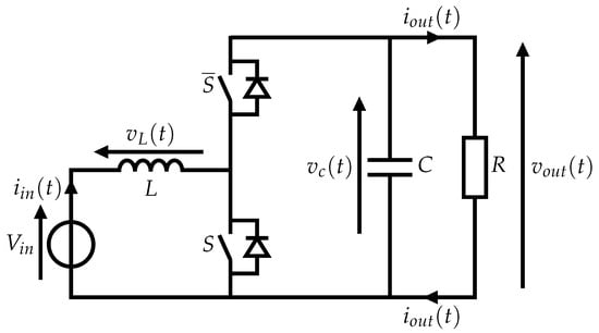
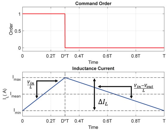
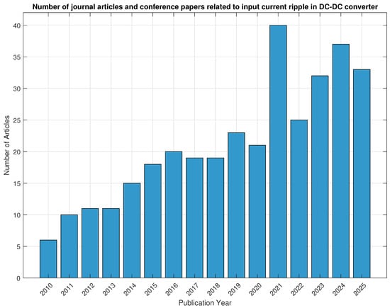
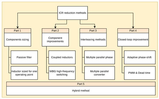
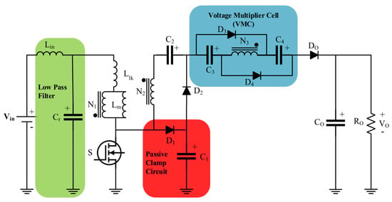
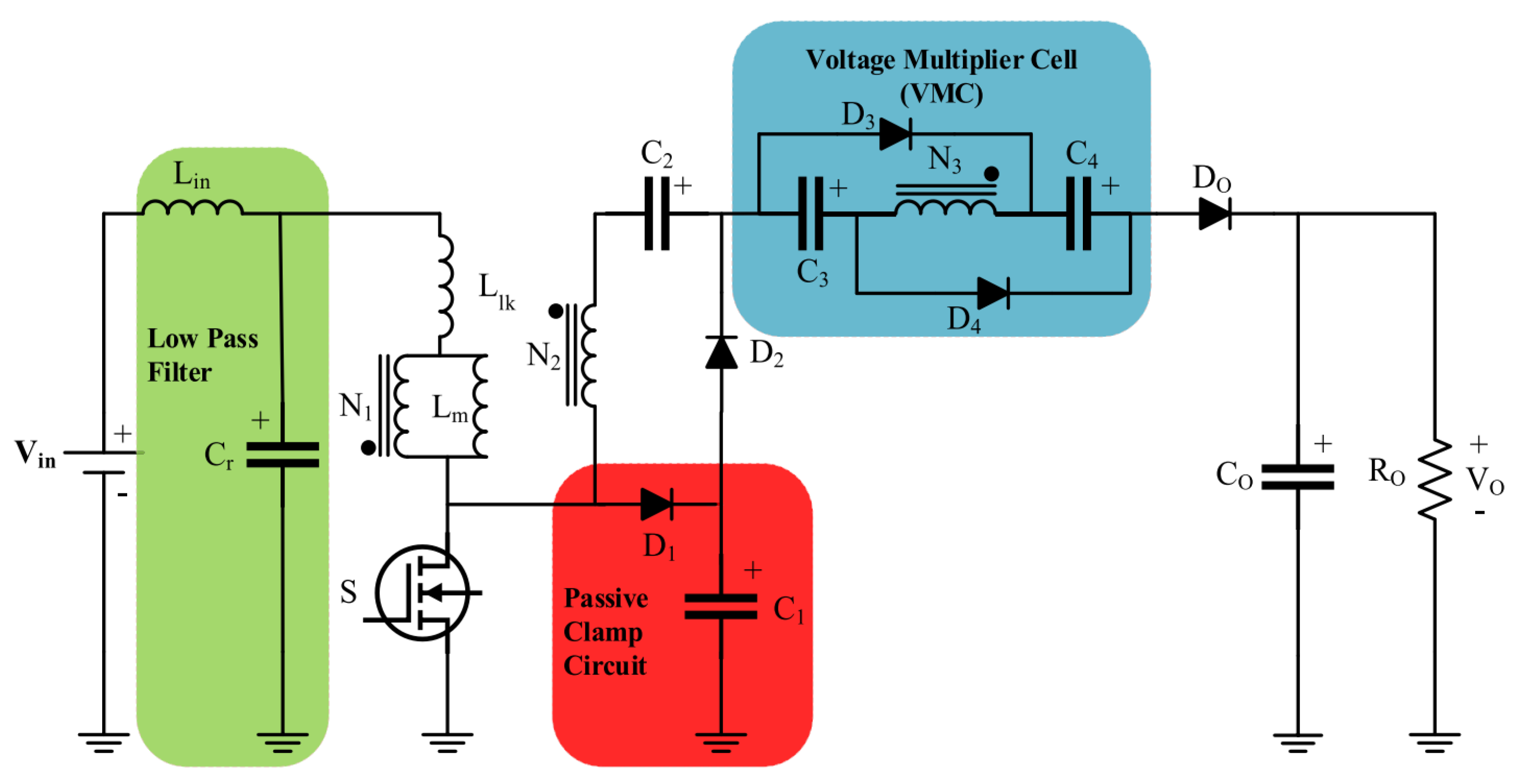
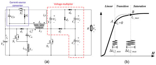
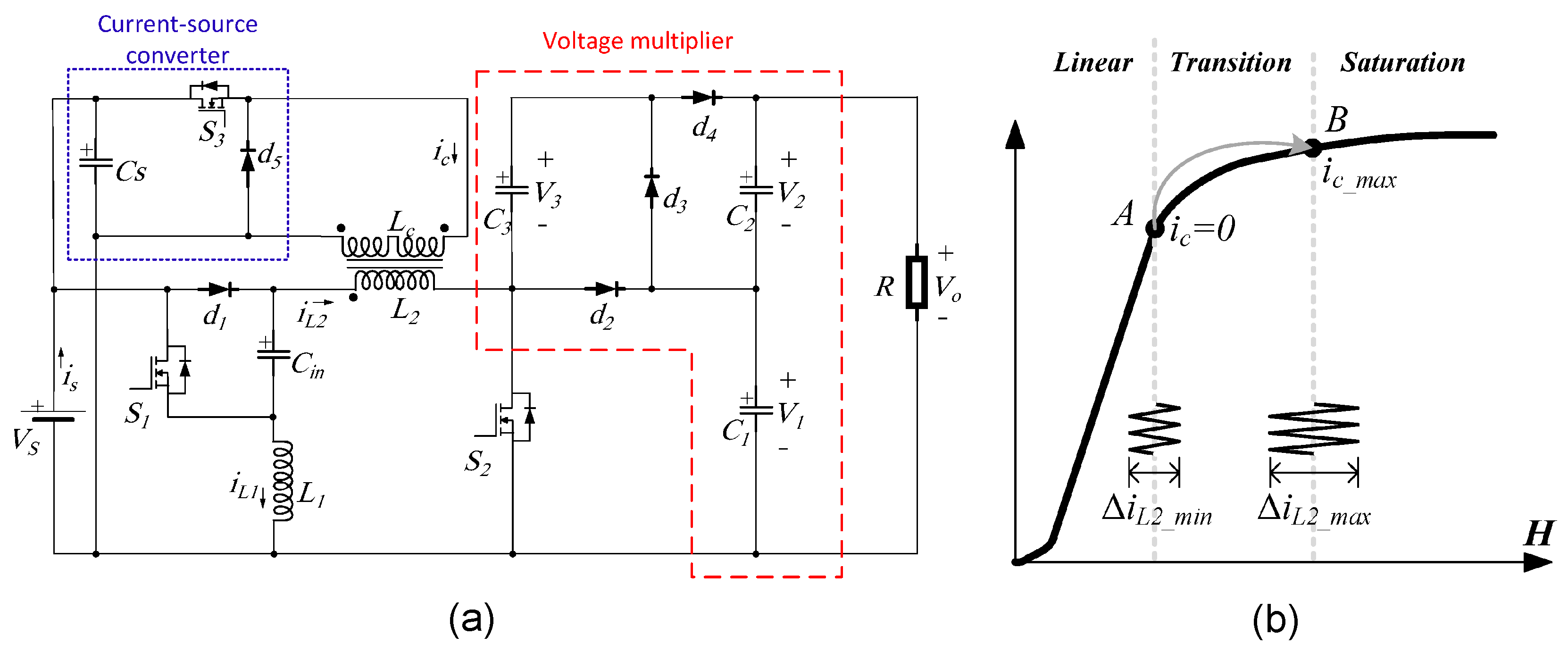
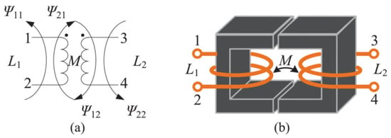
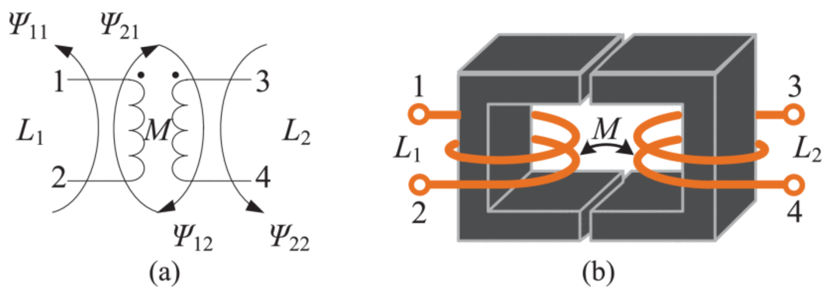
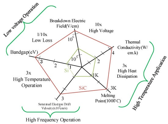

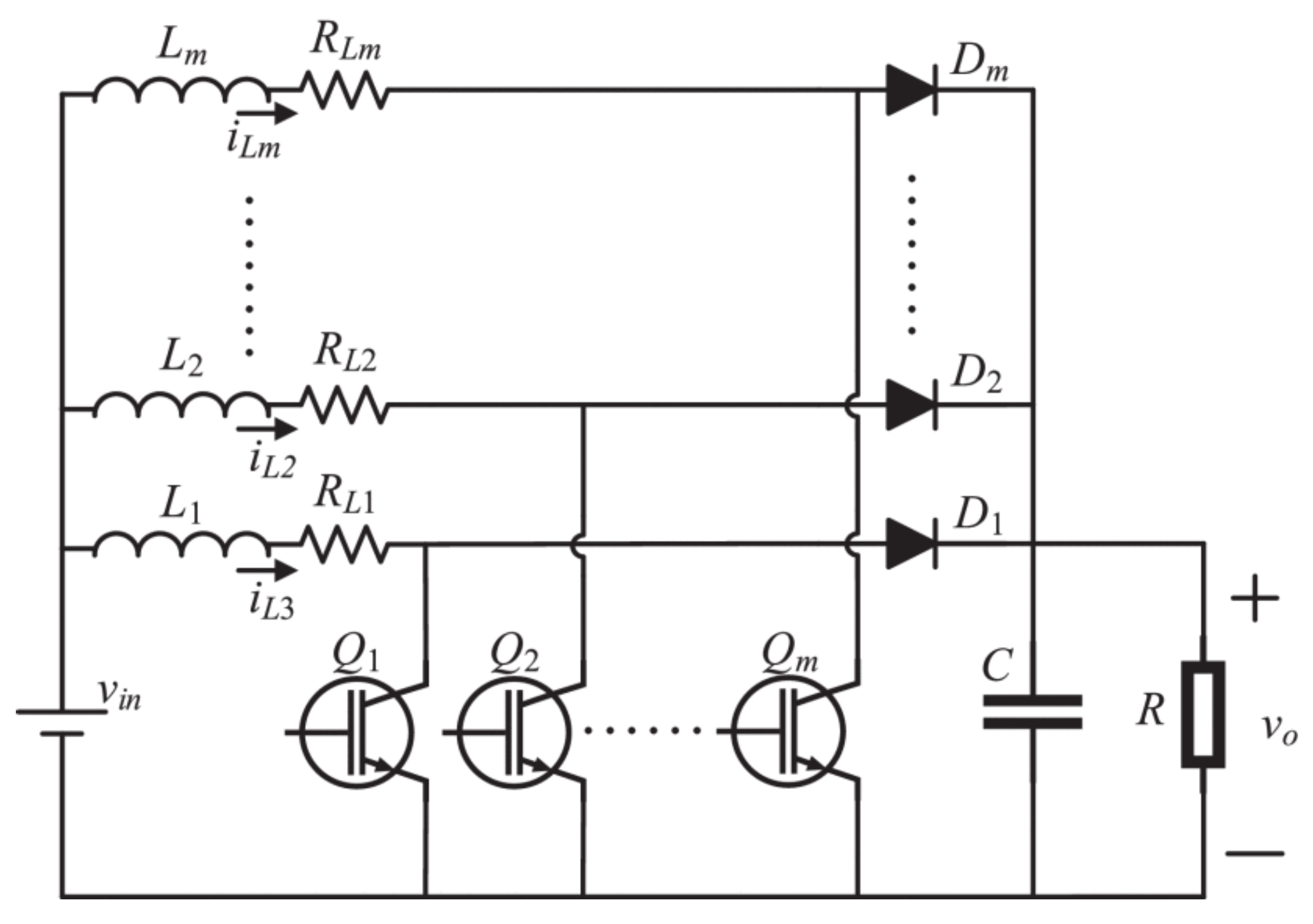
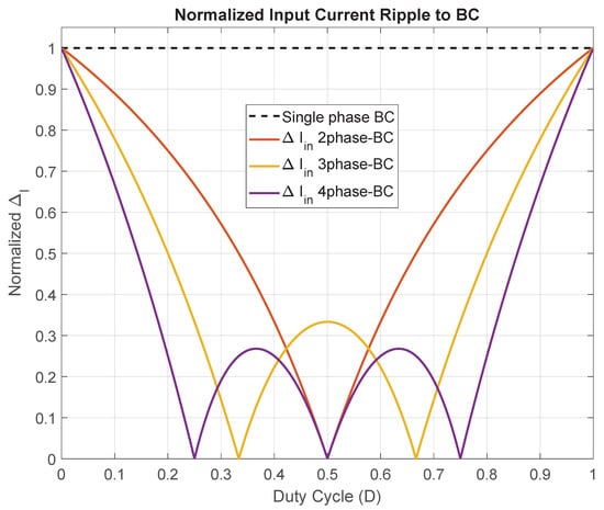
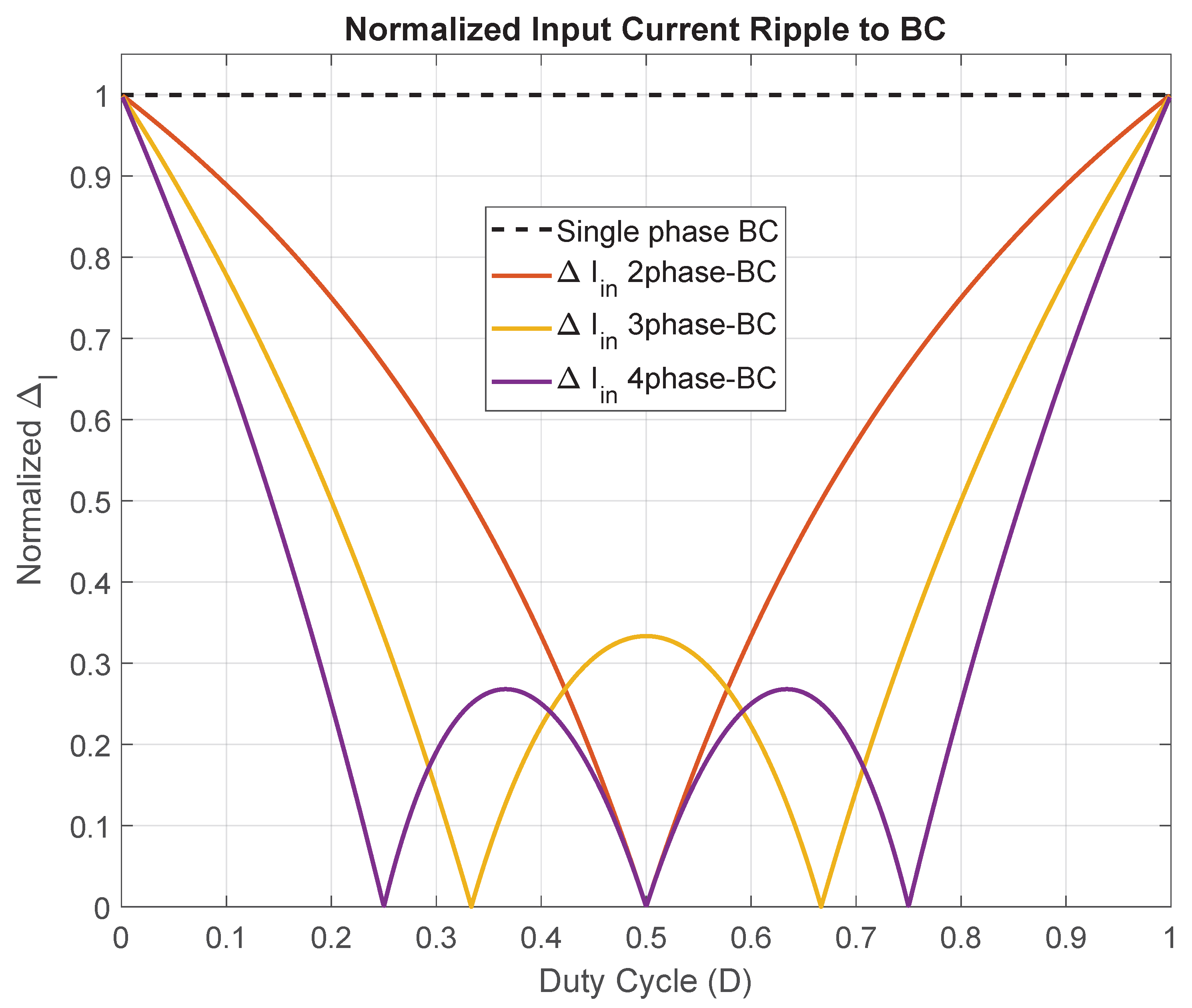
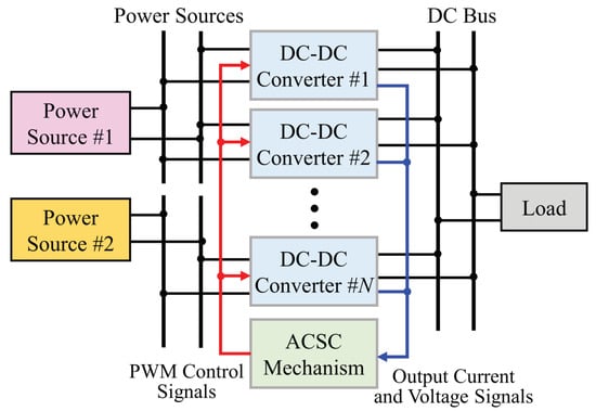
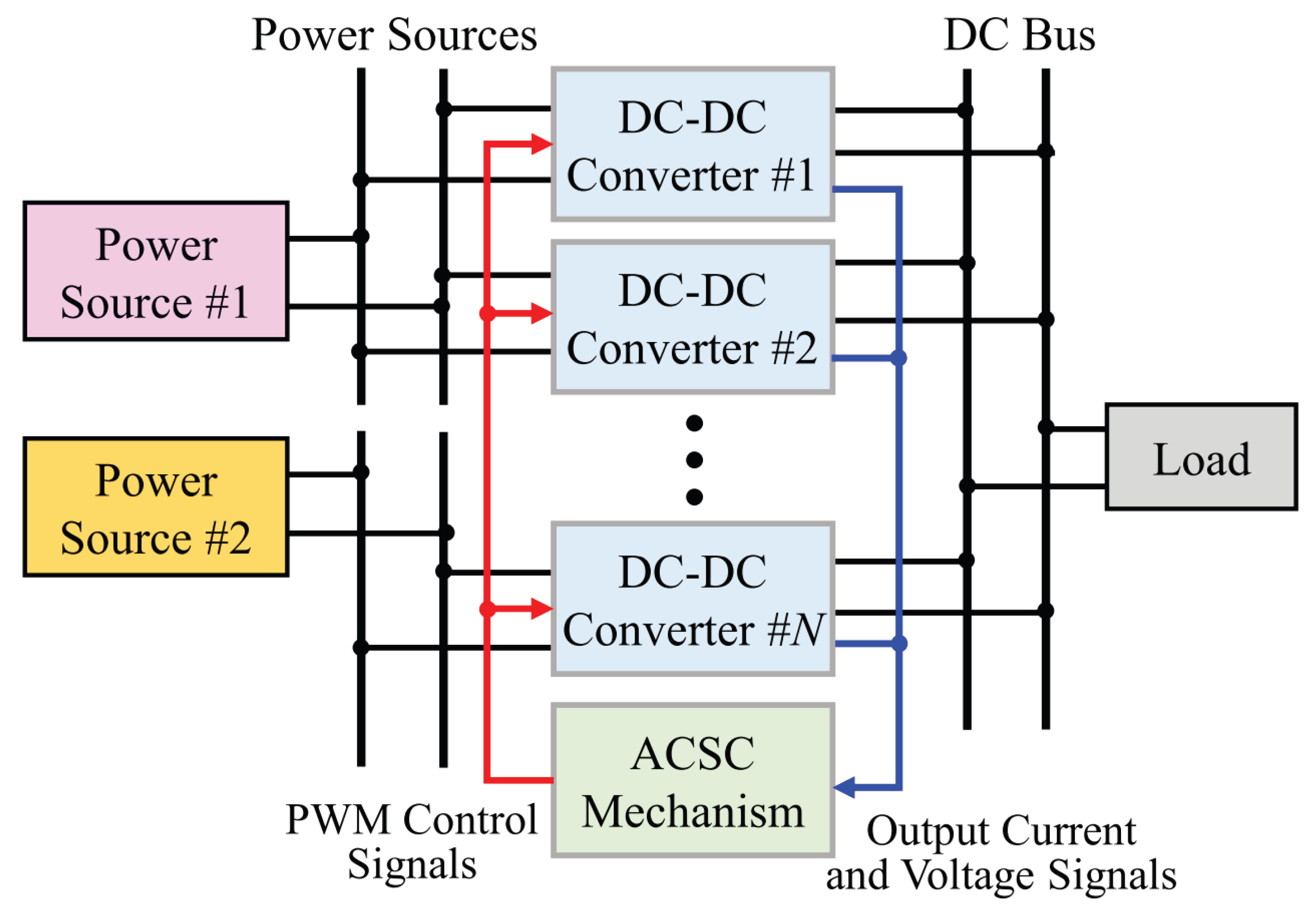
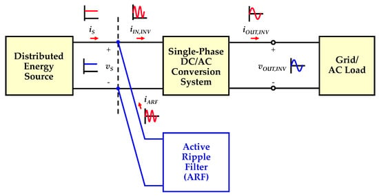
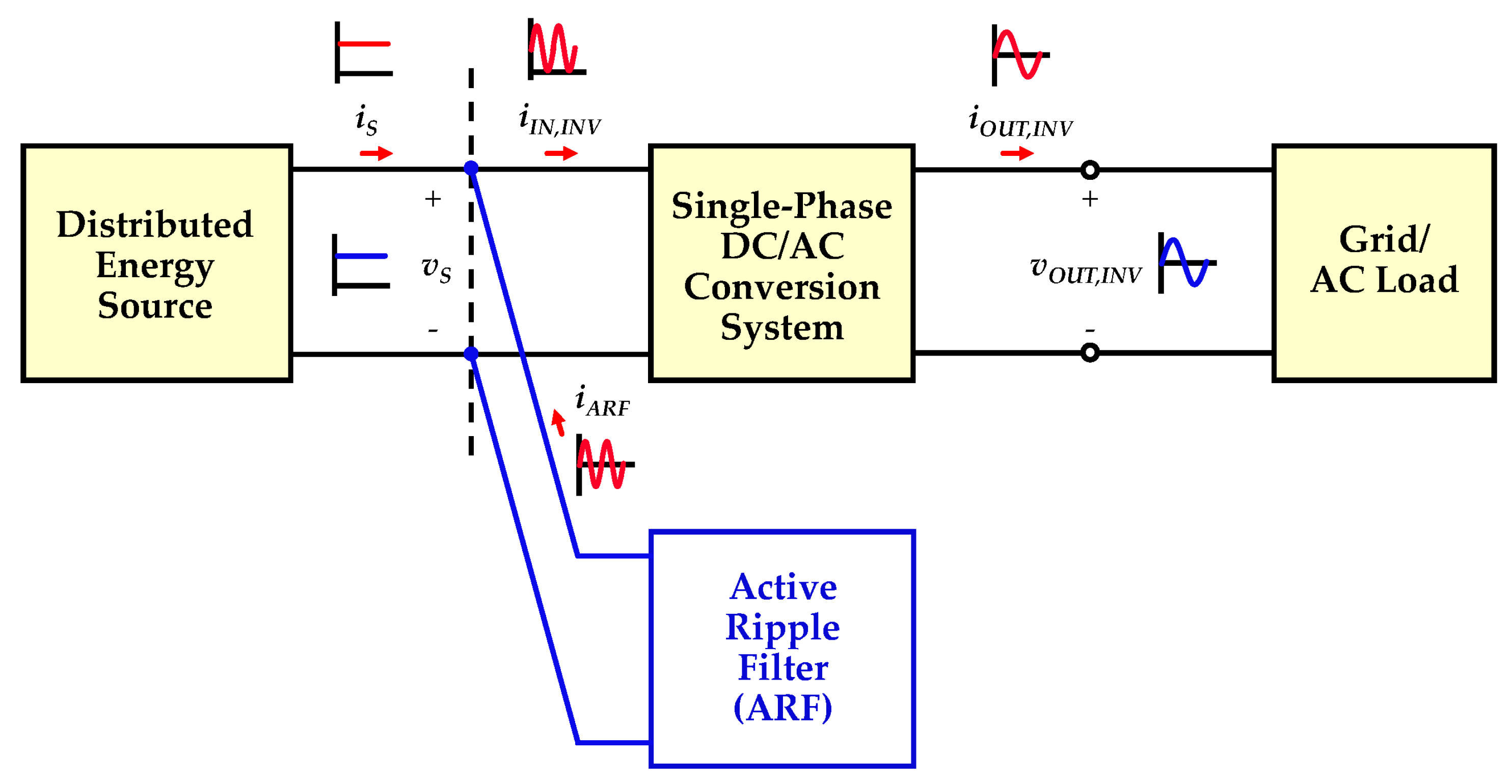

Disclaimer/Publisher’s Note: The statements, opinions and data contained in all publications are solely those of the individual author(s) and contributor(s) and not of MDPI and/or the editor(s). MDPI and/or the editor(s) disclaim responsibility for any injury to people or property resulting from any ideas, methods, instructions or products referred to in the content. |
© 2026 by the authors. Licensee MDPI, Basel, Switzerland. This article is an open access article distributed under the terms and conditions of the Creative Commons Attribution (CC BY) license.