


Abstract
Power electronic converters play an important role in proton exchange membrane (PEM) electrolyzers, where current ripple has been associated with electrode potential fluctuations, electrocatalyst degradation, and long-term system durability. This paper presents a unified analytical framework for multicell interleaved Buck DC-DC converters with parallel switching arms intended for low-ripple operation in electrochemical energy conversion systems. Existing steady-state analytical models are generally topology-specific and require new derivations for different converter configurations, limiting scalability and design flexibility. The proposed formulation considers a converter composed of k interleaved cells and M parallel switching arms per cell, resulting in a generalized converter architecture where the total number of switching devices is n = kM. Closed-form expressions are derived for the DC voltage gain, inductor current ripple, electrolyzer voltage ripple, and capacitor RMS current. The analysis shows that ripple cancellation and ripple-frequency multiplication are governed by the operating-region distribution and the total number of switching devices. In addition, normalized closed-form expressions are developed to establish scalable ripple-oriented design charts applicable to arbitrary converter configurations. By enabling the identification of operating conditions that minimize current ripple, the proposed methodology provides practical guidelines for the design of power converters supplying PEM electrolyzers and other catalyst-based electrochemical energy conversion systems. Consequently, the proposed model contributes to the development of power electronic interfaces that mitigate electrical stress on electrocatalysts, supporting improved durability and reliability of electrochemical energy conversion systems.
1. Introduction
The global energy transition toward decarbonization has driven a significant increase in electricity demand for applications such as electric vehicle traction systems and fast-charging infrastructures [1]. At the same time, green hydrogen production through proton exchange membrane (PEM) water electrolysis has emerged as one of the most promising technologies for large-scale renewable energy storage and decarbonization, further increasing the demand for high-efficiency power electronic conversion systems [1,2].
In this context, the interface between the power source and the load, in both battery-based systems and PEM electrolyzers, requires highly efficient and reliable DC–DC converters [3]. Furthermore, the quality of the delivered power is of paramount importance, since current and voltage ripple may degrade system performance. The main effects include increased thermal losses, reduced electrolyzer lifetime, and accelerated degradation of lithium-ion cells [2,3,4]. In general, reducing or completely eliminating ripple components can improve the overall efficiency of these systems [4]. In energy storage systems and green hydrogen production plants, DC-DC converters are required to interface the DC bus with loads such as batteries and electrolyzers [3]. Studies have shown that the performance of PEM electrolyzers can be adversely affected by voltage and current fluctuations, since power quality is a critical factor in these systems. In addition to reducing the electrical efficiency of the power conversion stage, excessive current ripple may decrease electrolyzer efficiency and accelerate degradation mechanisms associated with electrocatalytic components and membrane durability during long-term operation [4,5]. Therefore, minimizing current ripple has become an important design objective for power converters supplying PEM electrolyzers, not only to improve electrical performance but also to provide more stable operating conditions for electrochemical energy conversion processes [4,5].
Although current ripple is commonly analyzed in terms of converter efficiency [6], its impact extends beyond the electrical domain and directly affects the electrochemical behavior of the electrolyzer. Parache et al. reported, based on a 3000-h durability study of PEM electrolyzers, that triangular current ripple at 10 kHz increased the high-frequency resistance and intensified mass transport limitations [5]. In addition, previous studies have shown that larger current ripple results in higher specific energy consumption, indicating that more electrical energy is required to produce the same amount of hydrogen [6,7]. These current fluctuations also cause variations in the electrode potential, which can accelerate degradation processes, including catalyst dissolution, particle agglomeration, reduction in the electrochemically active surface area, and membrane deterioration. Consequently, reducing the current ripple is important not only for the electrical performance of the converter but also for enhancing the durability and energy efficiency of PEM electrolyzers.
Although the impact of current ripple on PEM electrolyzers has been widely investigated, the electrical behavior of these devices is not purely resistive. PEM electrolyzers exhibit nonlinear and frequency-dependent impedance, which depends on operating conditions such as current density, temperature, and pressure [8,9]. These characteristics can influence the interaction between the electrolyzer and its power converter, particularly when transient or frequency-dependent behavior is considered. Nevertheless, for steady-state converter analysis and analytical design, the electrolyzer can be represented by an equivalent resistive load associated with its operating point. This approximation is adopted in the present work to enable the derivation of closed-form expressions for the converter electrical characteristics and ripple behavior.
This phenomenon is inherent to switched-mode converters, which requires converter topologies capable of minimizing output ripple. In fact, power fluctuations and current ripples have been shown to significantly affect the degradation of electrocatalytic electrodes, with the waveform shape playing a critical role in the degradation rate [10]. Among the converter structures that meet the requirements of low current and voltage ripple, high power density, reliability, and efficiency, interleaved converters represent an attractive solution [2]. In this regard, the Interleaved Buck Converter (IBC) has become an attractive solution, as it distributes the load current among multiple phases, which reduces thermal stress and semiconductor losses [2,11]. In addition, the interleaving technique increases the frequency of the output ripple to multiples of the switching frequency, enabling a reduction in the size and volume of the passive filters employed [12,13]. Furthermore, studies on the impact of high-frequency current ripples on electrochemical systems have shown that, depending on the system and operating conditions, ripple effects can vary from negligible to severe, reinforcing the need for case-specific converter design [14].
Structurally, the IBC can be composed of multiple parallel-connected phases or cells derived from the conventional Buck converter topology [2,15,16]. For high-power applications, the literature suggests the use of multiple parallel switches per phase in order to increase current capability and system scalability, while also reducing conduction losses per device. However, this configuration introduces challenges such as current sharing and semiconductor asymmetry, thereby requiring robust control strategies [1,17,18,19]. In [2,20], an evolved variation of the Stacked Interleaved Buck Converter (SIBC) was proposed, in which an auxiliary circuit injects a compensating current to suppress the ripple generated by the main circuit. Furthermore, ref. [21] pointed out that the analysis of interleaved converters is complex, since the state-space models and voltage gains vary according to the converter configuration and load conditions, requiring specific analyses for each arrangement. These topologies have been validated in electrolysis systems, where ripple minimization is a critical requirement. In [3,22,23], interleaved topologies were shown to be among the most attractive solutions for electrolyzer applications, as they not only improve system efficiency but also mitigate premature electrode degradation mechanisms caused by AC components in the converter output current.
However, it can be observed in the literature that steady-state analysis models are, in most cases, developed specifically for each topology, which limits their generalization and hinders their application to different converter configurations [15,24,25,26]. As a consequence, any topological modification requires new theoretical developments, making the design process less efficient. In [18], a modular interleaved Boost DC-DC converter is proposed, focusing on modularity and scalability, while also presenting a mathematical development tailored to the specific topology. Although its equations for the converter RMS currents are adaptable, they are still derived from a fixed topology. In [2], a multi-cell ripple-free Stacked Interleaved Buck Converter is presented, whose analysis is conducted in a generalized manner to promote ripple cancellation through an auxiliary circuit. Nevertheless, the work does not provide a detailed analysis capable of covering arbitrary configurations, since the design of the employed semiconductors is not explicitly addressed. In [20], a multi-cell Stacked Interleaved Buck Converter (SIBC) intended for water electrolysis applications is presented. Similar to [2], the work in [20] focuses on current ripple suppression through an auxiliary circuit. Although it provides a detailed mathematical description of the RMS stresses on the components, it does not offer a structural generalization. Consequently, if the converter is expanded to a topology with additional switches, the entire mathematical formulation must be rederived. Furthermore, the analysis does not partition the duty cycle into operating regions, which increases the complexity of the mathematical formulation.
In [24,25], the ripple expressions and design parameters are derived exclusively for the presented two-cell (two-phase) topology, which limits their extension to higher-power applications. Other studies, such as [11,23,27,28], focus on the control of Interleaved Buck Converter-based topologies, aiming to reduce output current and voltage ripple while also mitigating current-sharing imbalance among the converter phases. Nevertheless, these works still employ mathematical models tailored to the specific configuration under investigation. Therefore, a generalized modeling approach capable of distinguishing the converter operating regions would provide greater flexibility and facilitate the adaptation of different topological structures to the proposed control models.
In [15], a behavioral analysis is employed for fault diagnosis in n-cell (multi-phase) interleaved Buck converters, presenting a generalized mathematical formulation for expanding the number of phases. However, this approach is restricted to fault diagnosis and does not provide a unified framework capable of describing the overall converter behavior, including static gain, operating regions, and electrical stresses for different architectures. Works such as [26,29,30] present generalized approaches, although they are directed toward the specific objectives of each study. In [29], the analysis focuses on phase selection for ripple reduction, but it employs a complex method to derive the ripple coefficient expression and does not present the complete converter behavior as a function of the number of parallel phases. Similarly, in [30], although the term “n-phase” is adopted and the ripple coefficient is generalized, no expressions are provided to predict the converter behavior independently of the intended application. Furthermore, the operation is not divided into duty cycle intervals associated with different operating regions. This limitation hinders the fast and accurate design of passive components and reduces the effectiveness of predicting thermal stresses even before the control-loop design stage.
Given the growing demand for Interleaved Buck Converters capable of processing higher power levels, reducing electrical stresses on semiconductor devices, and meeting strict power-quality requirements for PEM water electrolysis systems, converter topologies have evolved toward more complex architectures with a larger number of phases, additional switches, and increasing complexity. However, modifications in the topology configuration typically require new analytical developments and topology-specific mathematical formulations, which limit the flexibility and agility required to develop new converter structures for low-ripple electrochemical power interfaces.
This work proposes a generalized mathematical model for the analysis and design of IBC converters based on a modular architecture composed of k phases and M parallel switches per phase, allowing the representation of multiple topological configurations. The proposed approach enables a unified analysis for different converter configurations while simplifying the design process of power converters intended for PEM electrolyzers.
The converter operation is divided into multiple regions through pulse-width modulation (PWM) signals, where the parallel switches are driven with the same pulse widths while remaining uniformly phase-shifted. The switching sequence distributes the commutation instants among phases and branches, resulting in an equivalent ripple frequency proportional to the total number of converter switches and corresponding to a multiple of the switching frequency. These characteristics reduce the required inductance and, consequently, the volume of the magnetic components, while also enabling a reduction in the output capacitance and facilitating ripple cancellation, which contributes to improving the quality of the electrical power supplied to electrochemical systems.
Beyond converter design, the proposed analytical framework provides a systematic framework for selecting converter operating conditions compatible with the low-ripple operation required by electrochemical systems employing electrocatalysts. By enabling the systematic design of low-ripple converter configurations, the proposed model supports the development of power interfaces that can improve the operational stability, energy efficiency, and long-term durability of PEM electrolyzers.
2. Mathematical Analysis of the Continuous Conduction Mode Operation
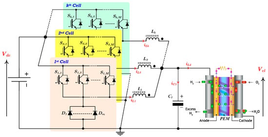
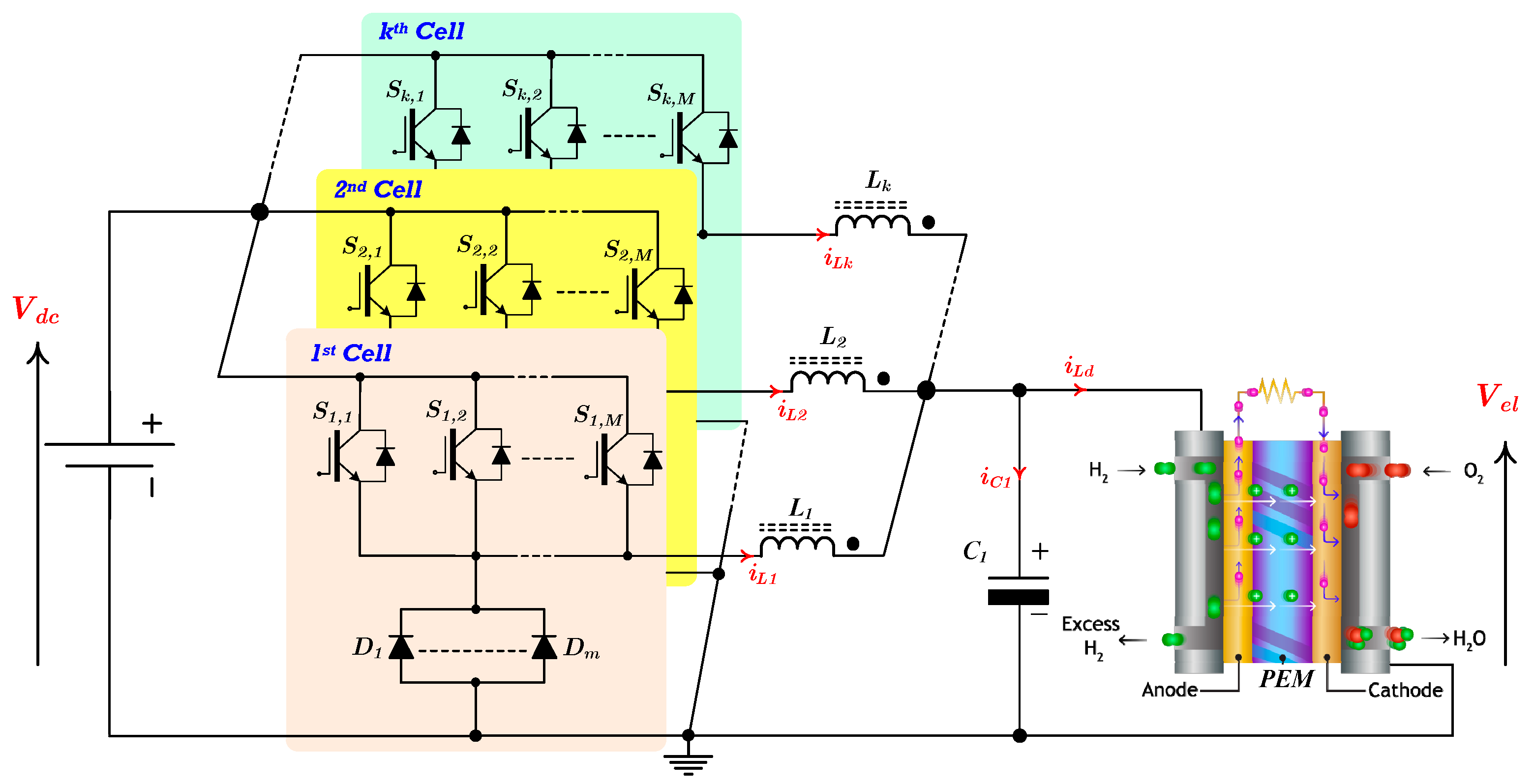
Figure 1 shows the topology of the interleaved DC-DC converter considered in the mathematical modeling. The converter consists of k parallel-connected cells, each composed of M parallel arms, where k and M are integer parameters defining the converter structure. Each arm comprises a controlled switch in series with a diode, corresponding to a basic Buck converter configuration. The total number of switches is n, given by n equal to k times M. Each cell is associated with an inductor L, assumed identical for all cells, which provides energy storage and transfer to electrolyzer. Therefore, the total number of inductors equals the number of cells k. The interleaved operation ensures that only one switch per cell conducts at any given time, yielding an approximately continuous electrolyzer current obtained from the sum of the inductor currents. The analysis is carried out assuming continuous conduction mode (CCM), such that the current in each inductor satisfies iL(t) > 0 for all time instants.
Figure 1.
Proposed DC–DC converter topology for PEM electrolyzer applications, used as the basis for the generalized mathematical model.
The converter operation is partitioned into k distinct operating regions, denoted as Ri. Each region is defined according to its corresponding duty cycle DRi. The region index i is an integer variable bounded between 1 and k, and each operating region represents a specific switching interval within the converter period for which a unique circuit configuration applies.
The total number of operating regions equals the number of cells, k. Each region Ri, with i ranging from 1 to k, corresponds to a specific duty cycle interval, as defined in (2). For i = k, the ratio k/n reduces to 1/M.
2.1. Switching States Analysis
A switching period consists of 2n operating stages, with a maximum switch conduction time equal to TS/M. Due to topology symmetry, all odd intervals are equal and all even intervals are equal, i.e., Δt1 = Δt3 = … = Δt2n−1 and Δt2 = Δt4 = … = Δt2n. The interval durations depend on the active operating region. The odd stages (Δt1, Δt3, …, Δt2n−1), which correspond to the time intervals [t1 − t0] = [t3 − t2] = … = [t2n−1 − t2n−2], and the even stages (Δt2, Δt4, …, Δt2n), which correspond to the time intervals [t2 − t1] = [t4 − t3] = … = [t2n − t2n−1], are described by (3) and (4), respectively.
The total conduction time of each switch within the operating region Ri is expressed as a function of the time intervals associated with the odd and even switching states, as defined in (5).
2.2. Switching Sequence Matrix
Since the converter comprises M switches per cell and k cells, resulting in a total of n switches, a switching-instant matrix is defined to characterize the turn-on instants of each switch. The position of each switch in the circuit, denoted by Sj,m, is arranged in a k by M matrix, as given in (6), where the index j in the set {1, 2, …, k} identifies the cell (row) and m in the set {1, 2, …, M} identifies the corresponding arm (column).
The turn-on instants of each switch are defined by (7).
Since the conduction time is defined as D multiplied by TS, the turn-off instant is therefore defined by (8).
This relationship defines the required phase shift among the arms and cells to ensure current sharing, reduce inductor and electrolyzer current ripple, and provide additional ripple cancellation, while simplifying PWM implementation. From (7), the PWM matrix given in (9) is derived. This matrix provides a compact representation of the PWM interleaving of the switches over a switching period.
2.3. Generalized DC Voltage Gain
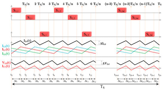
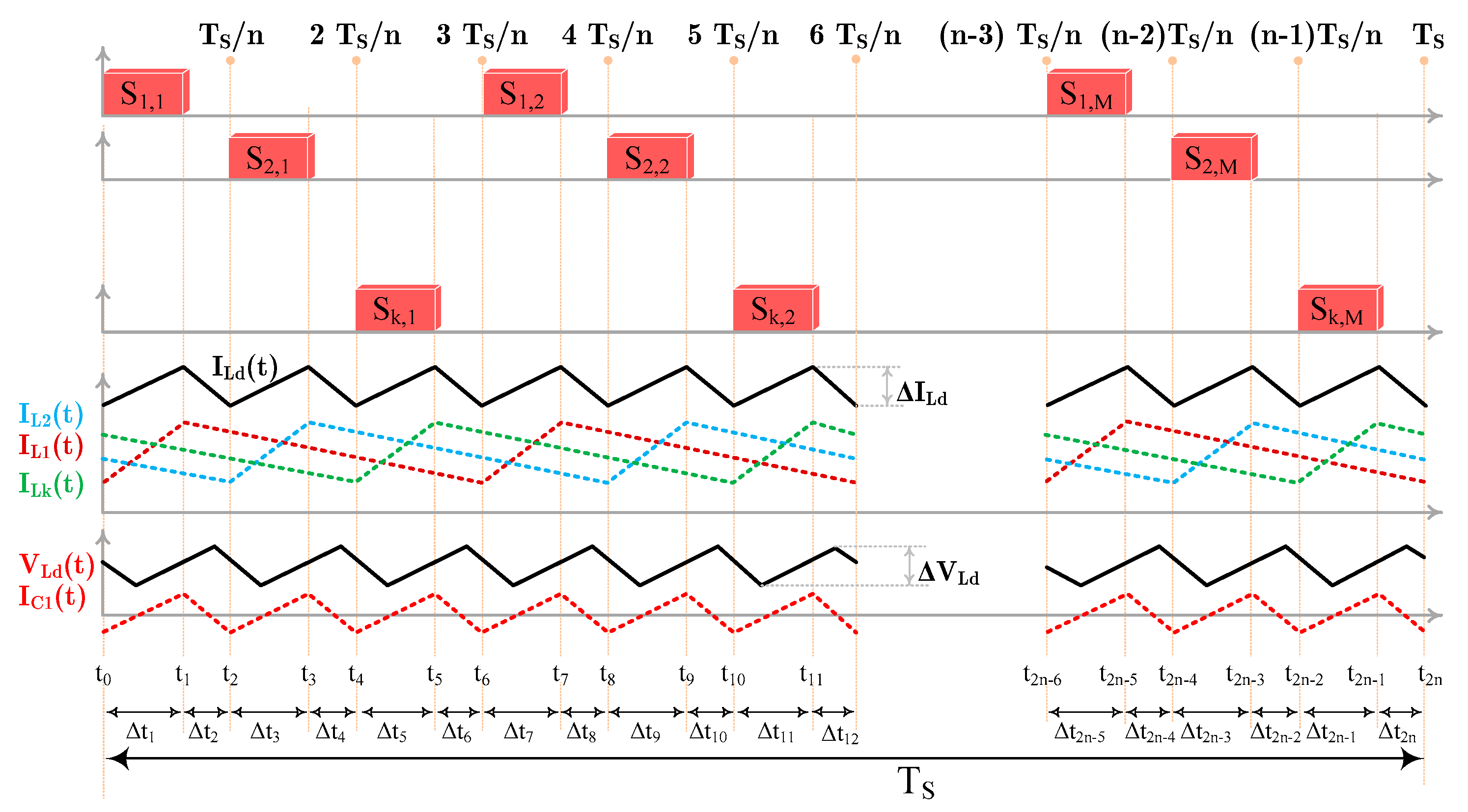
The DC gain is derived from the inductor flux-balance condition in steady state. For inductor L1, the energy storage interval is DRi TS, while the energy transfer interval is (k TS/n) − D TS, as illustrated in Figure 2. Using n = k M, the energy transfer interval simplifies as given in (10).
Figure 2.
PWM switching signals Sj,m with uniform PWM phase shifts in TS/n, illustrating the sequential activation of the switches over one switching period TS.
Due to the parallel configuration of the arms (or switches) within each cell, the fundamental frequency of the inductor voltage and current is M times the switching frequency fS. Under steady-state conditions, the average voltage across inductor L1 over one switching period is zero, as given by (11).
Solving (11) yields (12), which leads to the expression of the DC voltage gain of the converter, valid for any operating region.
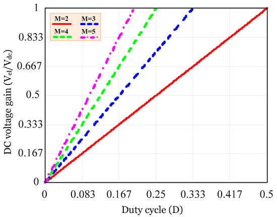
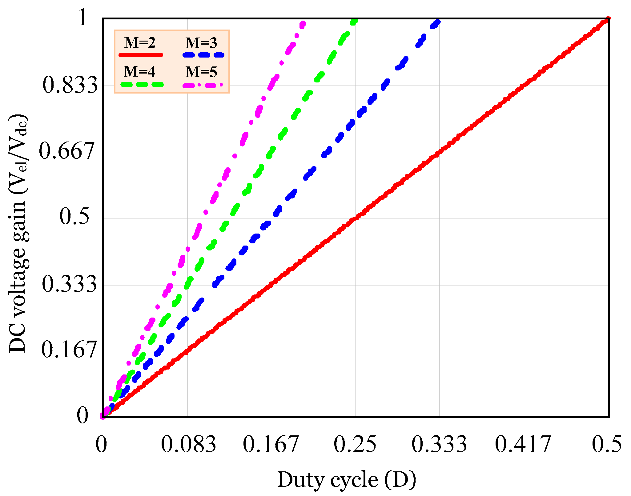
Figure 3 illustrates the DC voltage gain in CCM for different operating regions and distinct configurations of the number of parallel switches per phase. It can be observed that the DC voltage gain is independent of the number of phases (k) and is determined exclusively by the number of parallel switches (M) and the duty cycle corresponding to each operating region. This characteristic provides additional flexibility in converter design, allowing different topological configurations to be selected while maintaining the desired voltage conversion ratio for low-ripple power interfaces supplying PEM electrolyzers.
Figure 3.
DC voltage gain (Vel/Vdc) as a function of the duty cycle for different numbers of parallel switches per phase in the proposed converter for PEM electrolyzer applications.
3. Passive and Semiconductor Component Design
This section presents the criteria used for inductor sizing and the evaluation of the current and voltage stresses on the converter switches and diodes. The derived expressions are valid for any operating region and for arbitrary values of k and M. During the energy transfer stage, the voltage applied to each inductor is −Vel. Owing to the topology symmetry, the current ripple is identical in all inductors. The minimum inductance value required to ensure CCM operation is determined by (13).
Although the proposed mathematical model assumes identical inductors () to simplify the analysis and obtain closed-form expressions, in practice, inductance values are subject to manufacturing tolerances and may vary with temperature and current due to magnetic core effects. Such variations can introduce phase-current imbalances and affect the cancellation of the total electrolyzer current ripple.
To assess the sensitivity of the model, the inductance of the j−th cell can be expressed as , where L is the nominal inductance and delta represents its relative deviation. According to (13), and assuming that the other operating parameters remain unchanged, the current ripple of each inductor is inversely proportional to its inductance. Thus,
Therefore, inductance tolerances directly affect the individual cell-current ripples and may reduce the ideal cancellation of the total current ripple. Nevertheless, when the control strategy maintains balanced average phase currents, the resulting total-current ripple remains relatively close to the value predicted by the ideal model. The actual ripple deviation depends on the inductance mismatch, operating point, duty cycle, phase dis-placement, and current-control strategy.
Since the converter employs one inductor per cell, the average current in each inductor is equal to the electrolyzer current divided by the number of cells k, as given in (15).
The average and rms values of the switch current, for arbitrary values of k and M, are given in (16).
Similarly, the average and rms values of the diode current are given in (17).
The maximum voltage stress across both the switches and the diodes is expressed in (18).
The analytical evaluation of converter stresses allows accurate component sizing and facilitates topology selection. This information is particularly useful for designing low-ripple converters intended for PEM electrolyzer applications.
4. Parametric Analysis of the Electrolyzer Current Ripple
The converter electrolyzer current, Iel(t), is defined as the sum of the instantaneous currents of each inductor, as expressed in (19).
From Figure 2, it can be observed that the maximum and minimum values of Iel occur exclusively at the switching instants, where a change in the derivative of Iel takes place. For operation in CCM, these values can be written as
From (20), the electrolyzer current ripple is defined by (21).
Alternatively, the electrolyzer current ripple is given by (22).
In a k-cell topology consisting of k inductors, the maximum and minimum values of the electrolyzer current are defined by (23).
By substituting (23) into (22), the electrolyzer current ripple can be explicitly written as
Equation (24) shows that the electrolyzer current ripple is obtained from the sum of the current variations in the k inductors. For the operating region Ri, the current variation in each inductor over the interval is determined from the inductor voltage according to (25).
By substituting (3) into (25), the electrolyzer current ripple for any operating region and any converter configuration is given by (26).
By normalizing (26) according to , the expression of the normalized current ripple is obtained in (27).
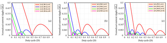
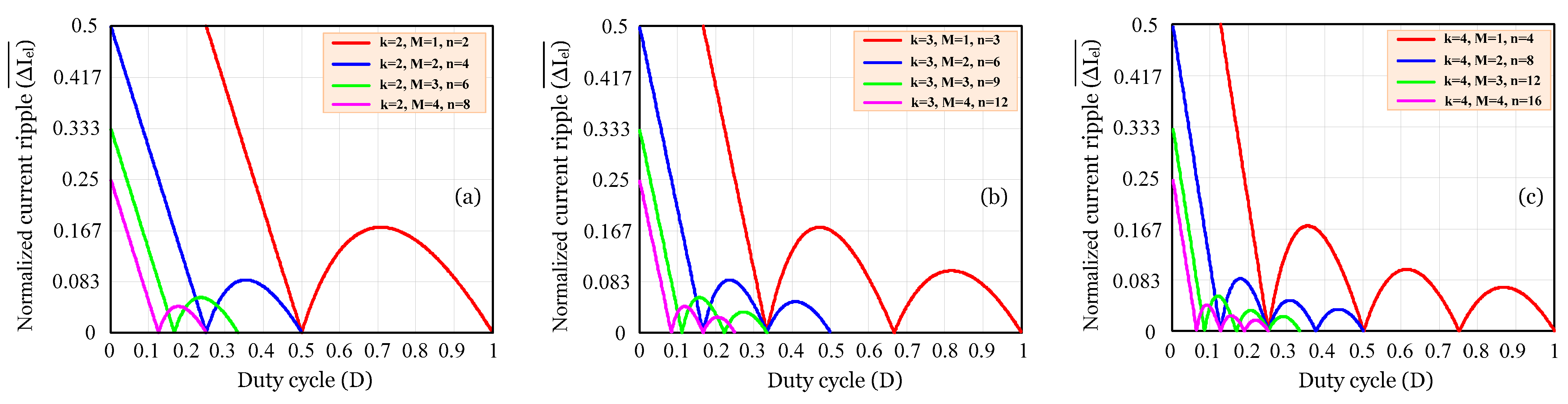
Figure 4 illustrates the normalized electrolyzer current ripple derived from (27) for different numbers of switches connected in parallel per cell (M) while maintaining a fixed number of cells: (a) k = 2, (b) k = 3, and (c) k = 4. As M increases, the ripple magnitude decreases over the entire duty cycle range. This behavior results from the current-sharing effect among parallel switches and the increase in the total number of switches (n = k M), which raises the electrolyzer current ripple frequency and enhances ripple cancellation. In addition, increasing the number of cells introduces additional ripple cancellation points due to the interleaved operation of the converter phases. Consequently, lower peak current ripple and smoother electrolyzer current waveforms are achieved, especially for configurations with larger values of k and M. These characteristics are particularly advantageous for applications requiring low current ripple, including battery charging systems and PEM electrolyzers. From the perspective of electrochemical energy conversion, lower current ripple reduces current and potential fluctuations at the electrolyzer terminals. Previous studies have shown that current ripple may influence electrochemical performance and degradation phenomena in PEM electrolyzers. Therefore, the generalized analytical model developed in this work provides a useful tool for designing low-ripple converter configurations for PEM electrolyzer applications.
Figure 4.
Normalized current ripple as a function of the duty cycle D for different converter configurations: (a) k = 2, (b) k = 3, and (c) k = 4.
From a practical perspective, the reduction in electrolyzer current ripple obtained through the proposed interleaved configurations can contribute to more stable electrical operating conditions at the electrolyzer terminals. As reported in the literature, current ripple can increase electrode potential fluctuations and specific energy consumption, while prolonged exposure to ripple conditions may contribute to degradation mechanisms affecting electrocatalytic components. Therefore, the identification of operating conditions and converter configurations with reduced current ripple is relevant not only to the electrical design of the power converter but also to reducing the electrical fluctuations experienced by the PEM electrolyzer during operation. However, the present work does not directly quantify the resulting changes in electrolyzer efficiency or long-term degradation, since the proposed model focuses on the steady-state electrical behavior of the converter. A detailed assessment of these electrochemical effects would require a frequency-dependent electrolyzer model and long-term experimental evaluation, which may be considered in future investigations.
5. Maximum and Cancellation Points of the Normalized Electrolyzer Current Ripple
By analyzing Figure 4 for all configurations, it can be observed that region R1 exhibits a linearly decreasing behavior throughout its entire operating range. Since the function is monotonically decreasing in this region, no internal local maxima exist. Therefore, the current ripple maxima occur only in the subsequent regions, where the function exhibits a downward-opening parabolic behavior between two consecutive ripple cancellation points. The duty cycle values corresponding to the maxima of the normalized current ripple are obtained by solving the derivative of (27), as expressed in (28).
Substituting (28) into (27) yields (29), which defines the maximum normalized electrolyzer current ripple.
The ripple cancellation points are determined by setting (27) equal to zero. Since the denominator does not affect the roots of the function, only the numerator is considered. Therefore, the ripple cancellation points are obtained by solving (nD − i + 1) (i − nD) = 0, which yields (30). These duty cycle values correspond to the points at which the normalized current ripple is completely canceled, defining the boundaries of each parabolic ripple region. Such operating points are particularly suitable for applications requiring very low or zero current ripple, such as electrolyzers and batteries.
6. Electrolyzer Voltage Ripple and Capacitor Current Analysis
Since the converter operates as a Buck-type topology, the electrolyzer voltage ripple can be expressed as a function of the electrolyzer current ripple, the switching frequency, the filter capacitance, and the total number of switches, resulting in (31).
By substituting (26) into (31), the expression for the electrolyzer voltage ripple for any k and M configuration is obtained in (32).
By normalizing (32) with respect to the normalized voltage ripple formulation presented in (33).
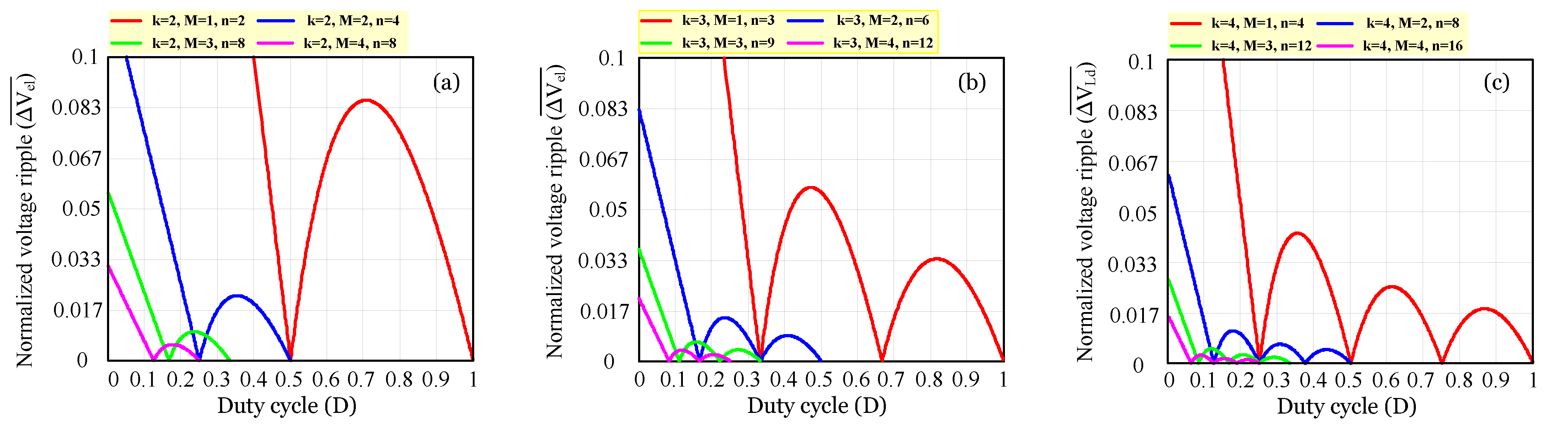
Figure 5 shows the normalized voltage ripple as a function of the duty cycle (D), obtained from (33), for different converter configurations. As shown in Figure 5a–c, increasing the number of cells (k) introduces additional ripple cancellation points throughout the duty cycle operating range, resulting in a significant reduction in the maximum voltage ripple. For k = 2, only one internal ripple cancellation point is observed, whereas for k = 3 and k = 4, additional cancellation points appear, dividing the ripple profile into multiple regions with lower peak values. Furthermore, for a given number of cells (k), increasing the number of parallel switches per cell (M) reduces the voltage ripple magnitude over the entire operating range. This behavior results from the increase in the total number of switches (n) and the corresponding increase in the number of available current conduction paths provided by the proposed converter structure. Therefore, increasing both k and M simultaneously contributes to reducing the ripple peaks and increasing the number of ripple cancellation points, thereby improving the overall converter performance.
Figure 5.
Normalized electrolyzer voltage ripple as a function of the duty cycle D for different converter configurations: (a) k = 2, (b) k = 3, and (c) k = 4.
These characteristics highlight the capability of the developed mathematical model to accurately predict the voltage ripple behavior and to identify converter configurations that provide reduced ripple levels, which is particularly relevant for applications requiring low-ripple operation, including PEM electrolyzers and hydrogen fuel cell systems. For electrochemical energy conversion systems, reduced voltage and current ripple contribute to more stable operating conditions. Therefore, the proposed analytical model can assist in selecting converter configurations that satisfy the low-ripple requirements of PEM electrolyzer applications.
Based on the waveforms shown in Figure 2, the rms current of the output capacitor is derived by applying the integral over one switching period, resulting in the expression given in (34).
Following the same procedure adopted for the electrolyzer voltage ripple analysis, the capacitor rms current is normalized, resulting in (35).
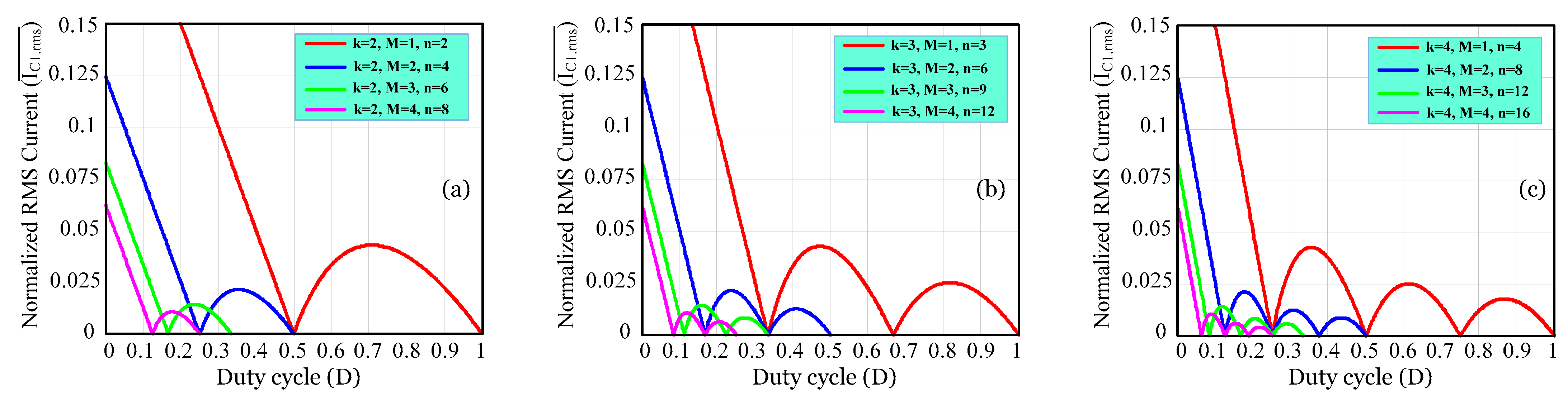
Figure 6 presents the normalized RMS current of capacitor C1 as a function of the duty cycle (D) for different values of k, M, and n. As illustrated in Figure 6a–c, the RMS current exhibits several zero-current points distributed along the duty cycle range. These points correspond to the duty cycle values predicted by the analytical model at which the RMS current of capacitor C1 becomes zero. As the number of cells (k) increases, additional zero-current points appear within the operating range. For k = 2, only a limited number of zero-current points are observed. In contrast, for k = 3 and k = 4, the current profile is divided into a larger number of intervals, each characterized by lower RMS current levels. Consequently, the peak RMS current decreases as the converter employs more cells. For a fixed value of k, increasing the number of parallel switches per cell (M) further reduces the RMS current magnitude. This behavior is associated with the increase in the total number of switches (n) and the corresponding distribution of current among a greater number of conduction paths. As a result, the current stress on capacitor C1 is reduced, leading to lower RMS current values throughout the duty cycle range.
Figure 6.
Normalized RMS current of capacitor C1 as a function of the duty cycle for different values of the parameters k, M, and n: (a) k = 2, (b) k = 3, and (c) k = 4.
These zero-current points are particularly advantageous because they represent operating conditions where the RMS current of capacitor C1 is theoretically zero. At these duty cycle values, losses associated with the capacitor equivalent series resistance (ESR) are minimized, reducing power dissipation and improving converter efficiency. In addition, lower RMS current levels contribute to reduced capacitor heating, increased component lifetime, and more compact capacitor design. These characteristics are desirable for power converters supplying PEM electrolyzers, where efficient operation and low current ripple are important design requirements.
7. Maximum and Cancellation Points of the Normalized Electrolyzer Voltage Ripple and Rms Current of Capacitor C1
Following the methodology established in Section 5, the normalized voltage ripple analysis is performed for the considered configuration. As shown in Figure 5, region R1 exhibits a linear decrease over the entire operating range for all considered configurations. Since the normalized current ripple is a monotonically decreasing function in this region, no local maximum exists within its boundaries. Consequently, the ripple maxima occur only in the subsequent regions, where the ripple characteristic follows a downward-opening parabolic profile between two consecutive ripple-cancellation points. The maximum duty cycle values corresponding to the maximum normalized voltage ripple are obtained by setting the derivative of (33) equal to zero, yielding (36).
Evaluating (33) at the duty cycle value given by (36) leads to (37), representing the maximum normalized electrolyzer voltage ripple.
The electrolyzer voltage ripple cancellation points are obtained by setting (33) equal to zero and solving the resulting equation, yielding (38). It can be observed that these duty cycle values coincide with the electrolyzer current ripple cancellation points. At these operating points, the normalized electrolyzer voltage ripple is completely eliminated. Therefore, such operating conditions are particularly attractive for applications that demand highly regulated output characteristics, such as electrolyzers and other energy storage systems.
To determine the maximum duty cycle and the maximum normalized RMS current, as well as the duty cycle value corresponding to the RMS current cancellation point shown in Figure 6, the same procedure described previously is applied using (35). The maximum duty cycle is obtained by solving the derivative of (36), resulting in (39).
Substituting the duty cycle value defined in (39) into (35) yields (40), which corresponds to the maximum normalized RMS current.
The normalized RMS current cancellation points are obtained from (41). At these operating points, the normalized RMS current becomes zero, eliminating the capacitor RMS current and the associated ESR losses. Consequently, thermal stress is reduced, converter efficiency is improved, capacitor lifetime is extended, and the volume of the energy storage stage can be reduced.
8. Comparison of the Proposed Model for Different Interleaved Converter Configurations
The proposed model is evaluated through comparison with analytical formulations reported for different interleaved Buck converter topologies. The comparison considers the DC voltage gain, electrolyzer voltage ripple, electrolyzer current ripple, and capacitor RMS current, as well as the degree of generalization with respect to the operating region index, the number of cells, the number of parallel switching arms, the total number of switching devices, and the analytical derivation of the main converter design parameters. As summarized in Table 1, most existing analytical models have been developed for specific converter configurations and therefore require a new formulation whenever the converter architecture, the number of cells, or the number of switching devices is modified. References [2,16,20,26] provide analytical expressions for converter operation and current ripple; however, their formulations are restricted to particular topologies and do not provide generalized expressions with respect to the operating region index, the number of cells, the number of parallel switching arms, or the total number of switching devices. Although [20] additionally derives an analytical expression for the electrolyzer current ripple, its applicability remains limited to the converter structure considered in that work. The generalized analytical approaches reported in [15,29,30] extend the analysis to an arbitrary number of switching devices. However, these formulations do not establish a region-based analytical description and therefore cannot describe the converter behavior as a function of the operating region index. In addition, they do not provide a generalized formulation that simultaneously accounts for the number of cells and the number of parallel switching arms.
Table 1.
Comparison of the proposed mathematical modeling framework with existing analytical models for interleaved DC–DC buck converters.
Among the reviewed studies, ref. [31] represents the most comprehensive analytical approach, being the only previous work that provides analytical expressions as functions of both the number of parallel switching arms and the total number of switching devices, while also deriving models for the DC voltage gain, electrolyzer current ripple, electrolyzer voltage ripple, and capacitor RMS current. However, the formulation remains associated with a specific multicell converter architecture and does not establish a unified region-based analytical framework applicable to arbitrary operating region indices, numbers of cells, numbers of parallel switching arms, and total numbers of switching devices.
A further comparison can be made by considering how the analytical formulations respond to changes in the converter configuration. In the existing models, the number of cells and/or switching arms is generally embedded in the derivation of the corresponding converter topology. Therefore, a change in the converter architecture may require the analytical expressions to be rederived for the new configuration. In the proposed framework, the converter configuration is incorporated directly through the parameters (k), (M), and (n), where (n = kM), while the operating condition is represented by the region index (i). Consequently, the same analytical formulation can be retained when the converter dimensions are changed, without requiring a new derivation for each specific topology.
Moreover, by assigning specific values to (k) and (M), the proposed formulation reduces to particular converter configurations considered in previous studies. Thus, the analytical models reported in the literature can be regarded as particular cases within the proposed generalized framework, whereas the proposed formulation remains applicable when the number of cells, parallel switching arms, or total number of switching devices is modified. This capability provides a direct mathematical link between specific converter models and the generalized formulation proposed in this work.
In contrast, the proposed model provides a unified region-based analytical framework that simultaneously generalizes the converter analysis with respect to the operating region index, the number of cells, the number of parallel switching arms, and the total number of switching devices. Based on this formulation, closed-form expressions are derived for the DC voltage gain, electrolyzer current ripple, electrolyzer voltage ripple, and capacitor RMS current, regardless of the converter dimensions. Furthermore, normalized design charts are obtained directly from the analytical model, enabling systematic converter sizing and ripple-oriented design.
The applicability of the proposed framework is particularly relevant to PEM electrolyzer power interfaces, where different power ratings and electrical operating conditions may require different numbers of interleaved cells and parallel switching arms. The proposed formulation allows these alternative configurations to be evaluated using the same analytical framework, avoiding the need to develop a separate mathematical model for each converter configuration. In addition, the region-based formulation enables the operating regions associated with different ripple characteristics to be identified directly from the analytical expressions.
For PEM electrolyzer applications, the proposed analytical formulation also provides a practical tool for selecting converter configurations capable of reducing current ripple during the design stage. Since low current ripple is an important requirement for power interfaces supplying electrochemical systems, the proposed model facilitates the identification of operating conditions suitable for PEM electrolyzer applications. Therefore, besides providing a scalable mathematical formulation for converter analysis, the proposed model also offers a systematic approach for the design of low-ripple DC-DC converters intended for electrochemical energy conversion systems.
As shown in Table 1, the proposed framework is the only analytical model among the compared studies that simultaneously combines region-based operation, scalability with respect to the number of cells, the number of parallel switching arms, and the total number of switching devices, together with closed-form derivations of the main electrical and design parameters within a single mathematical formulation.
9. Validation of the Proposed Analytical Model Through Simulation
To verify the accuracy of the proposed analytical formulation, a detailed simulation study was performed using OrCAD® (Cadence Design Systems, Inc., San Jose, CA, USA) under the operating conditions summarized in Table 2. The selected converter configuration consists of k = 3 cells, M = 3 parallel switching arms per cell, and n = 9 switching devices. The converter operates in region i = 2 with a duty cycle of D = 0.188, a switching frequency of 25 kHz, three identical inductors of 250 µH, and an output capacitor of 50 µF. The selected operating point is within the CCM and was chosen to evaluate the analytical expressions under a representative operating condition of the proposed generalized model.
Table 2.
Converter parameters used to validate the proposed analytical model through simulation.
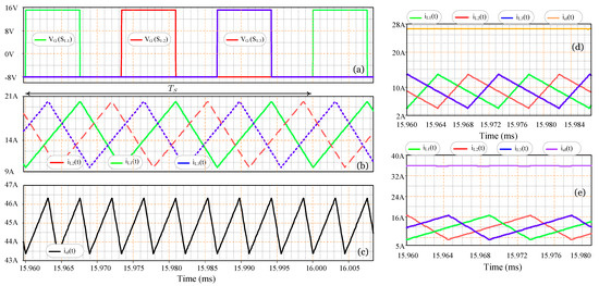
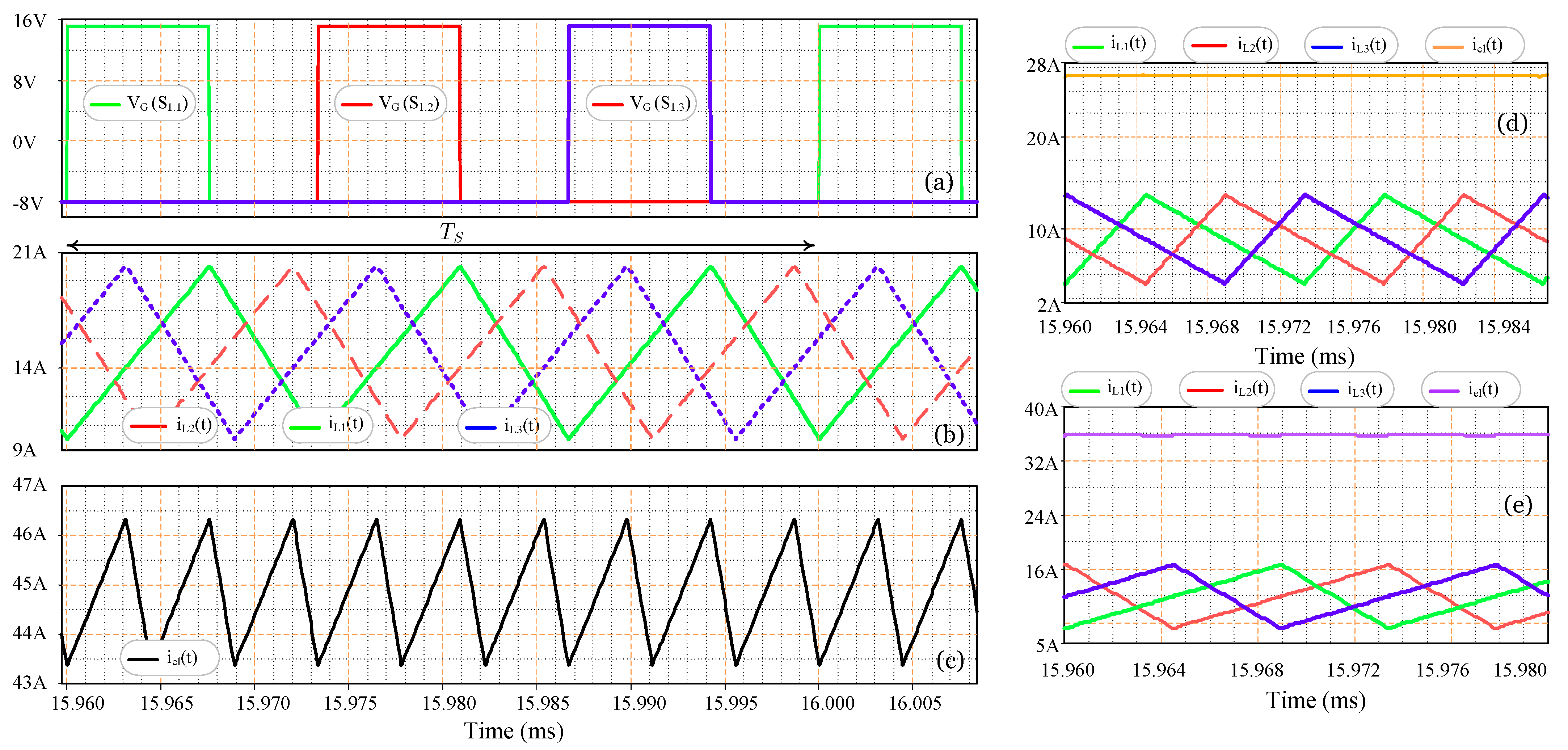
Figure 7a shows the gate-drive signals applied to switches S1.1, S1.2, and S1.3. The signals have the same duty cycle and are phase-shifted according to the interleaved switching strategy adopted for the three-cell configuration, as illustrated in Figure 2. Figure 7b shows the currents through the three inductors. The three currents are balanced and exhibit the expected triangular waveform under CCM operation. The simulated inductor current ripple is 10.51 A, while the ripple frequency is three times the switching frequency due to the interleaved operation. Figure 7c presents the simulated output current, with a current ripple of 2.9 A. The output current ripple frequency is nine times the switching frequency, resulting from the combined interleaving of the three cells and the parallel switching arms.
Figure 7.
Simulation results for the three-cell converter: (a) gate-drive signals, (b) inductor currents, (c) electrolyzer current, (d) ripple cancellation at D = 1/9, and (e) ripple cancellation at D = 2/9.
The reduction from the individual inductor current ripple to the total electrolyzer current ripple also confirms the ripple-cancellation mechanism described by the proposed model. To further verify the ripple cancellation points predicted by the analytical formulation, Figure 7d,e present detailed comparisons between the individual inductor currents and the resulting electrolyzer current for two specific duty-cycle values. Figure 7d corresponds to (D = 1/9), which is one of the analytically predicted ripple cancellation points for (n = 9). At this operating condition, the ripple components of the individual inductor currents are phase-shifted such that they cancel each other completely in the total electrolyzer current. Consequently, the electrolyzer current exhibits an approximately constant waveform, confirming the zero-ripple condition predicted by the analytical model.
Figure 7e presents the same waveforms for (D = 2/9), which corresponds to the next ripple cancellation point predicted by the analytical formulation for the considered converter configuration. Again, the phase-shifted inductor current ripples cancel when the individual currents are summed, resulting in a substantially reduced, ideally zero electrolyzer current ripple. These simulation results provide a direct graphical verification of the ripple cancellation points predicted by the analytical model and are consistent with the normalized current, voltage, and capacitor-current characteristics presented in Figure 4, Figure 5 and Figure 6. Therefore, the results in Figure 7d,e further confirm that the ripple cancellation conditions identified analytically are effectively reproduced by the switching simulation.
Table 3 compares the quantities calculated from (13), (26), (32), and (34) with the corresponding results obtained from simulation. For the considered configuration, the calculated inductor current ripple is 10.4 A, while the simulated value is 10.51 A, showing close agreement between the analytical model and the simulation. Similarly, the electrolyzer current ripple obtained from (26) is 3.061 A, compared with 2.9 A from the simulation. This agreement confirms that the analytical expression correctly predicts the resulting output current ripple produced by the interleaved operation of the converter cells. For the electrolyzer voltage ripple, (32) gives 34.01 mV, whereas the simulated result is 32.8 mV. The close correspondence between these values confirms the validity of the proposed analytical expression for predicting the output voltage ripple. Finally, the RMS current of capacitor (C1) calculated from (34) is 765 mA, compared with 857 mA obtained from the simulation. The results remain in good agreement and confirm that (34) provides a consistent estimation of the capacitor current stress.
Table 3.
Comparison between calculated and simulated results for k = 3, M = 3, n = 9, and i = 2.
The close correspondence between the calculated and simulated results for all the evaluated quantities demonstrates the consistency of the proposed analytical model. In particular, the agreement observed for the inductor current ripple, electrolyzer current ripple, electrolyzer voltage ripple, and capacitor RMS current supports the validity of (13), (26), (32), and (34), respectively.
10. Conclusions
A unified analytical model was developed to obtain closed-form expressions for the DC voltage gain, inductor current ripple, electrolyzer voltage ripple, and capacitor RMS current for arbitrary values of the number of cells k, and parallel switching arms, M. The resulting normalized design charts provide a practical framework for converter sizing and the selection of configurations that satisfy the ripple requirements of PEM electrolyzer applications.
The proposed methodology establishes a scalable analytical approach for multicell interleaved Buck converter architectures with multiple operating regions and uniformly phase-shifted switching sequences. Unlike conventional approaches employing identical gate signals for parallel switches, the proposed PWM strategy distributes the switching instants among cells and switching arms, promoting balanced current sharing while enhancing ripple cancellation.
The developed formulation further demonstrates that ripple cancellation is intrinsically related to the converter operating conditions and the total number of switching devices. Consequently, the effective ripple frequency of the inductor currents becomes M times the switching frequency, whereas the electrolyzer voltage ripple frequency increases proportionally to k M. These characteristics enable a reduction in the required passive component values, leading to smoother current and voltage waveforms, reduced magnetic component volume, and improved suitability for applications requiring low current ripple, including PEM electrolyzers, battery charging systems, and hydrogen fuel cell systems.
The obtained analytical expressions and normalized design charts provide practical support for ripple-oriented converter design over a wide range of operating conditions. The proposed analytical formulation is particularly relevant for power converters supplying PEM electrolyzers, where limiting current ripple is an important design requirement. Since current ripple has been associated in the literature with electrode potential fluctuations and degradation phenomena affecting electrocatalysts and, indirectly, the membrane, the proposed model provides a systematic basis for selecting converter configurations and operating conditions compatible with electrochemical energy conversion systems.
Although the proposed model is exemplified for PEM electrolyzer applications, it is important to emphasize that the analytical framework is load-independent and applicable to any electrochemical energy conversion system that demands low output ripple. The generalized formulation depends solely on the converter structural parameters k, M, and n, and on the steady-state load resistance, without requiring specific electrochemical characteristics. Therefore, the same normalized design charts and closed-form expressions can be directly employed for battery chargers, fuel cell power interfaces, electrochemical reactors, and other systems where current and voltage stability are critical for performance and durability. The ripple cancellation points derived in this work provide universal design guidelines that enable systematic selection of operating conditions and converter configurations across a wide range of low-ripple applications.
Future work may extend the proposed model to include the dynamic impedance of the PEM electrolyzer to capture interactions between the power converter and the electrochemical system under transient conditions.
Author Contributions
Conceptualization, M.B.E.K. and L.H.S.C.B.; methodology, M.B.E.K., I.D.S.J. and R.M.; software, I.D.S.J. and M.B.E.K.; validation, all authors; formal analysis, M.B.E.K. and C.d.C.L.B.E.K.; investigation, M.B.E.K., I.D.S.J. and C.d.C.L.B.E.K.; resources, all authors; data curation, M.B.E.K., I.D.S.J. and R.M.; writing—original draft preparation, M.B.E.K. and P.P.P.; writing—review and editing, all authors; visualization, all authors; supervision, L.H.S.C.B.; project administration, L.H.S.C.B.; funding acquisition, M.B.E.K. All authors have read and agreed to the published version of the manuscript.
Funding
This work was supported in part by FUNCAP (Fundação Cearense de Apoio ao Desenvolvimento Científico e Tecnológico) and ECITECE (Secretaria da Ciência, Tecnologia e Educação Superior) through the Research and Innovation Network on Renewable Energy (Rede VERDES), Grant No. 07548003/2023.
Data Availability Statement
The data supporting the findings of this study are available within the article. Further information is available from the corresponding author upon reasonable request.
Acknowledgments
The authors gratefully acknowledge the support of FUNCAP (Fundação Cearense de Apoio ao Desenvolvimento Científico e Tecnológico) and ECITECE (Secretaria da Ciência, Tecnologia e Educação Superior) through the Research and Innovation Network on Renewable Energy (Rede VERDES). The authors also thank the Federal University of Ceará (UFC) for providing the research infrastructure and academic support.
Conflicts of Interest
The authors declare no conflicts of interest.
References
- Safayatullah, M.; Elrais, M.T.; Ghosh, S.; Rezaii, R.; Batarseh, I. A Comprehensive Review of Power Converter Topologies and Control Methods for Electric Vehicle Fast Charging Applications. IEEE Access 2022, 10, 40753–40793. [Google Scholar] [CrossRef] [Scilit]
- Alharbi, M.A.; Dahidah, M.S.A.; Ali, S.A.; Ethni, S.A.E.; Pickert, V. Ripple-Free Multiphase Interleaved Stacked Converter for High-Power Applications. IEEE Trans. Power Electron. 2022, 37, 14770–14780. [Google Scholar] [CrossRef] [Scilit]
- Guilbert, D.; Collura, S.M.; Scipioni, A. DC/DC converter topologies for electrolyzers: State-of-the-art and remaining key issues. Int. J. Hydrog. Energy 2017, 42, 23966–23985. [Google Scholar] [CrossRef] [Scilit]
- Buitendach, H.P.C.; Gouws, R.; Martinson, C.A.; Minnaar, C.; Bessarabov, D. Effect of a ripple current on the efficiency of a PEM electrolyser. Results Eng. 2021, 10, 100216. [Google Scholar] [CrossRef] [Scilit]
- Parache, F.; Schneider, H.; Turpin, C.; Richet, N.; Debellemanière, O.; Bru, É.; Thieu, A.T.; Bertail, C.; Marot, C. Impact of Power Converter Current Ripple on the Degradation of PEM Electrolyzer Performances. Membranes 2022, 12, 109. [Google Scholar] [CrossRef] [Scilit]
- Yodwong, B.; Guilbert, D.; Phattanasak, M.; Kaewmanee, W.; Hinaje, M.; Vitale, G. AC-DC Converters for Electrolyzer Applications: State of the Art and Future Challenges. Electronics 2020, 9, 912. [Google Scholar] [CrossRef] [Scilit]
- Guilbert, D.; Vitale, G. Improved Hydrogen-Production-Based Power Management Control of a Wind Turbine Conversion System Coupled with Multistack Proton Exchange Membrane Electrolyzers. Energies 2020, 13, 1239. [Google Scholar] [CrossRef] [Scilit]
- Elhawash, A.M.; Hussein, A.S.; Araújo, R.E.; Lopes, J.A.P. Low ripple adaptive lead-lag current controlled interleaved buck converter for PEM hydrogen electrolyzers. Control Eng. Pract. 2026, 174, 107029. [Google Scholar] [CrossRef] [Scilit]
- Ratib, M.K.; Muttaqi, K.M.; Islam, M.R.; Sutanto, D.; Agalgaonkar, A.P. Electrical circuit modeling of proton exchange membrane electrolyzer: The state-of-the-art, current challenges, and recommendations. Int. J. Hydrog. Energy 2024, 49, 625–645. [Google Scholar] [CrossRef] [Scilit]
- Liu, C.; Lin, B.; Zhang, H.; Wang, Y.; Wang, H.; Tang, J.; Zou, C. Influence of Power Fluctuation on Ni-Based Electrode Degradation and Hydrogen Evolution Reaction Performance in Alkaline Water Splitting: Probing the Effect of Renewable Energy on Water Electrolysis. Catalysts 2024, 14, 307. [Google Scholar] [CrossRef] [Scilit]
- Yodwong, B.; Sikkabut, S.; Guilbert, D.; Hinaje, M.; Phattanasak, M.; Kaewmanee, W.; Vitale, G. Open-Circuit Switch Fault Diagnosis and Accommodation of a Three-Level Interleaved Buck Converter for Electrolyzer Applications. Electronics 2023, 12, 1349. [Google Scholar] [CrossRef] [Scilit]
- Villarruel-Parra, A.; Forsyth, A.J. Modeling Phase Interactions in the Dual-Interleaved Buck Converter Using Sampler Decomposition. IEEE Trans. Ind. Electron. 2019, 66, 3316–3322. [Google Scholar] [CrossRef] [Scilit]
- Alajmi, B.N.; Marei, M.I.; Abdelsalam, I.; Ahmed, N.A. Multiphase Interleaved Converter Based on Cascaded Non-Inverting Buck-Boost Converter. IEEE Access 2022, 10, 42497–42506. [Google Scholar] [CrossRef] [Scilit]
- Stodel, M.; Pons, M.; Jarry, T.; Jaafar, A.; Lacressonniere, F.; Turpin, C.; Chattot, R.; Lenormand, P.; Tenailleau, C. Post-mortem analysis of high-frequency current ripples effects on HT-PEMFC aging. Int. J. Hydrog. Energy 2025, 138, 175–182. [Google Scholar] [CrossRef] [Scilit]
- Gupta, A.K.; Kumar, M. Characterization and Localization of Open Circuit Faults for n-Phase Interleaved Buck Converter. IEEE Trans. Ind. Appl. 2024, 60, 3273–3283. [Google Scholar] [CrossRef] [Scilit]
- Palma, L. Analysis and Selection of Step-Down Converter for PEM Electrolyzer Applications. In Proceedings of the 2024 International Symposium on Power Electronics, Electrical Drives, Automation and Motion (SPEEDAM), Napoli, Italy, 19–21 June 2024; IEEE: New York, NY, USA, 2024; pp. 1160–1165. [Google Scholar] [CrossRef] [Scilit]
- Alzahrani, A.; Devarajan, G.; Subramani, S.; Vairavasundaram, I.; Ogbuka, C.U. Analysis and validation of multi-device interleaved DC-DC boost converter for electric vehicle applications. IET Power Electron. 2023, 16, 1548–1557. [Google Scholar] [CrossRef] [Scilit]
- Ismail, A.H.; Uddin, M.F.; Sba, B.A.; Darvish, P.; Zhao, Y. A High-Density Modular DC–DC Converter Design With a Novel Planar Coupled Inductor. IEEE Trans. Transp. Electrif. 2026, 12, 119–131. [Google Scholar] [CrossRef] [Scilit]
- Xiao, Z.; Sun, T.; Yao, Z.; Tang, Y. Optimizing Multiphase DC–DC Converters via Interleaving/Intraleaving and Phase Shedding. IEEE Trans. Power Electron. 2026, 41, 6630–6646. [Google Scholar] [CrossRef] [Scilit]
- Sun, L.; Liu, Z.; Guo, X.; Wang, X.; Wang, L. Multi-Phase Stacked Interleaved Buck Converter for Hydrogen-Production Electrolysis with Low-Voltage-Stress Ripple Compensation Circuit. CSEE J. Power Energy Syst. 2026, 12, 401–410. [Google Scholar] [CrossRef] [Scilit]
- Kim, H.-C.; Biswas, M.; Park, J.-W. Discontinuous Conduction Mode Analysis of Two-Phase Interleaved Buck Converter with Inversely Coupled Inductor. IEEE Access 2024, 12, 91944–91956. [Google Scholar] [CrossRef] [Scilit]
- Guida, V.; Guilbert, D.; Douine, B. Candidate Interleaved DC-DC Buck Converters for Electrolyzers: State-of-the-Art and Perspectives. In Proceedings of the 2018 IEEE International Conference on Environment and Electrical Engineering and 2018 IEEE Industrial and Commercial Power Systems Europe (EEEIC/I&CPS Europe), Palermo, Italy, 12–15 June 2018; IEEE: New York, NY, USA, 2018; p. 6. [Google Scholar] [CrossRef] [Scilit]
- Makineni, R.R.; Agalgaonkar, A.P.; Muttaqi, K.M.; Islam, M.R.; Sutanto, D. Integral Sliding Mode Control of a Stacked Interleaved Buck Converter for Electrolyzers Supplied with Renewable Energy Sources. IEEE Trans. Ind. Appl. 2025, 61, 450–462. [Google Scholar] [CrossRef] [Scilit]
- El Kattel, M.B.; Mayer, R.; Oliveira, S.V.G.; De Jesus Cardoso Filho, B. Four-phase interleaved DC–DC step-down converter using coupled inductor for high power application. Int. J. Circuit Theory Appl. 2020, 48, 1696–1723. [Google Scholar] [CrossRef] [Scilit]
- Pang, Y.; Li, W.-L.; Sun, H.-X.; Pan, L.; Meng, F.-T.; Liang, Y. High-Efficiency Multiphase Stacked Interleaved DC-DC Buck Converter with Very Low Output Current Ripple and Low Current–Voltage Stress. J. Electr. Eng. Technol. 2024, 19, 4969–4988. [Google Scholar] [CrossRef] [Scilit]
- Yao, Z.; He, X.; Xiao, Z.; Deng, F.; Dai, C.; Lu, S. Current Ripple Prediction and ZVS-Based Variable Switching Frequency Control for Interleaved Multiphase Three-Level DC–DC Converter. IEEE Trans. Power Electron. 2025, 40, 5109–5119. [Google Scholar] [CrossRef] [Scilit]
- Koundi, M.; El Fadil, H.; Lassioui, A.; El Asri, Y. Adaptive Sliding Mode Control of an Interleaved Buck Converter–Proton Exchange Membrane Electrolyzer for a Green Hydrogen Production System. Processes 2025, 13, 795. [Google Scholar] [CrossRef] [Scilit]
- Mammeri, E.N.; Lopez-Santos, O.; El Aroudi, A.; Domajnko, J.; Prosen, N.; Martinez-Salamero, L. Modeling and Control of a Three-Phase Interleaved Buck Converter as a Battery Charger. IEEE Access 2025, 13, 18325–18345. [Google Scholar] [CrossRef] [Scilit]
- Duan, J.; Wang, S.; Xu, Y.; Fan, S.; Zhao, K.; Sun, L. Variable Multiple Interleaved Bi-Directional DC/DC Converter with Current Ripple Optimization. Appl. Sci. 2023, 13, 1744. [Google Scholar] [CrossRef] [Scilit]
- Meng, Z.; Duan, J.; Sun, L. Voltage Drop Compensation Technology for High-Voltage and High-Power DC Energy Storage Power Supply System. IEEE Trans. Ind. Electron. 2024, 71, 549–559. [Google Scholar] [CrossRef] [Scilit]
- El Kattel, M.B.; Pinheiro, G.J.O.; Mayer, R.; Junior, E.M.S.; Junior, D.S.O.; Barreto, L.H.S.C. Scalable Architecture of a 15 kW Multicell Interleaved M-Arm DC–DC Converter for High-Efficiency Power Processing in Green Hydrogen Electrolyzers. IEEE Access 2025, 13, 179166–179184. [Google Scholar] [CrossRef] [Scilit]

Disclaimer/Publisher’s Note: The statements, opinions and data contained in all publications are solely those of the individual author(s) and contributor(s) and not of MDPI and/or the editor(s). MDPI and/or the editor(s) disclaim responsibility for any injury to people or property resulting from any ideas, methods, instructions or products referred to in the content. |
© 2026 by the authors. Licensee MDPI, Basel, Switzerland. This article is an open access article distributed under the terms and conditions of the Creative Commons Attribution (CC BY) license.