


Abstract
Thermal management in deep-space environments remains a critical bottleneck for miniaturized energy systems due to the inherent absence of convective heat transfer. This study investigates the thermo-electrochemical coupling of a miniaturized Proton Exchange Membrane Fuel Cell (PEMFC) thermally integrated with a 10 W power electronic Printed Circuit Board (PCB) under high-vacuum conditions. Beyond conventional parametric studies, this work explores the synergistic interaction within six passive thermal control architectures, utilizing paraffin-based Phase Change Materials (PCMs) and high-conductivity graphite Thermal Interface Materials (TIMs). Transient numerical simulations reveal that unmanaged configurations lead to thermal runaway (>128 °C), critically threatening membrane hydration and electrochemical stability. In contrast, the development of a hybridized PCM-TIM architecture—comprising a 5 mm PCM and 10 mm TIM layer coupled with a radiative finned sink—established a high-efficiency thermal shunt. This optimized configuration stabilized the PEMFC at 60 °C and achieved superior temperature homogeneity (<67 °C) across the PCB surface. Furthermore, polarization curve analysis demonstrates that this passive strategy significantly mitigates voltage degradation and concentration losses at high current densities. These findings establish design scaling laws for convection-independent energy subsystems, providing a robust, lightweight, and scalable framework for future microsatellite power architectures in extraterrestrial environments.
1. Introduction
The near-total absence of atmospheric convection in space renders the thermal management of onboard systems particularly challenging. Unlike terrestrial environments, where heat can be dissipated efficiently through a combination of conduction, convection, and radiation, spacecraft in orbit must rely solely on internal conduction and thermal radiation to evacuate the heat generated by their systems [1].
This inherent thermal constraint has a direct impact on the reliability and operational lifespan of critical subsystems, especially energy generation units and sensitive electronic components. Inadequate thermal regulation can subject these components to extreme temperature fluctuations, potentially leading to performance degradation, premature failure, and, ultimately, the compromise of long-duration space missions [2].
In long-duration space missions, energy supply constitutes a fundamental pillar to ensure the uninterrupted operation of payloads, communication systems, scientific instruments, electrical power systems, as well as thermal control and propulsion devices. The onboard energy source must fulfill several critical criteria: high energy density, extended autonomy, resilience to extreme environmental conditions, and the ability to undergo repeated cycling without significant performance degradation [3]. While photovoltaic panels serve as the primary energy source in space, their reliance on direct solar radiation and their inability to provide continuous power—particularly during eclipse periods or when in shadowed regions—necessitate the integration of efficient energy storage and conversion systems. In response to these challenges, hybrid systems that combine energy generation, storage, and regeneration emerge as strategic solutions to secure the energy independence of satellites and space stations [4].
Proton exchange membrane fuel cells (PEMFCs) are garnering growing attention in the aerospace sector as a highly promising alternative energy solution, owing to their elevated power density, lightweight configuration, and emission-free operation [5,6,7,8]. In contrast to conventional energy conversion systems, PEMFCs emit only water as a byproduct of their electrochemical process [9], a feature that is critically advantageous for life support and resource recycling in closed-loop space habitats. In addition to these operational advantages, recent advances in PEMFC diagnostics highlight the role of electrochemical impedance spectroscopy (EIS) for fault detection and performance monitoring. Ma et al. [10] provide a comprehensive review of EIS-based methods, emphasizing their effectiveness in identifying degradation mechanisms and improving system reliability in embedded applications.
To meet the stringent demands of aerospace applications, PEMFCs must perform reliably under extreme operational conditions, including high altitudes characterized by severe thermal fluctuations and significantly reduced atmospheric pressure. Addressing these challenges necessitates the deployment of advanced engineering strategies that emphasize material resilience and energy efficiency, often taking precedence over cost-related constraints due to the paramount importance of reliability and mission safety in space environments [11]. Furthermore, system designs must rigorously comply with strict limitations on weight and volume, while ensuring stable performance in low-pressure operational contexts [12,13].
Thermal management systems play a pivotal role in maintaining optimal operating temperatures, which are essential for ensuring the consistent performance and longevity of proton exchange membrane fuel cells (PEMFCs). Aerospace PEMFCs are particularly vulnerable to harsh environmental conditions like low oxygen availability at high altitudes and significant thermal fluctuations [14]. The diminished partial pressure of oxygen necessitates the integration of advanced air compression or oxygen enrichment systems to sustain efficient electrochemical reaction kinetics [15]. Additionally, aerospace-grade PEMFC systems frequently incorporate protective coatings and specialized materials designed to withstand chemically aggressive atmospheric conditions and high radiation levels [16,17].
Temperature is a critical determinant of PEMFC performance, as thermal regulation directly impacts both the reaction kinetics and system efficiency. Elevated operational temperatures can enhance reaction rates, yet they may also contribute to increased voltage losses due to heightened ohmic and mass transport resistances [18,19].
Higher temperatures promote the vaporization of water within the membrane, thereby mitigating liquid water accumulation and improving heat utilization [20]. On the other hand, operating at lower temperatures makes water management simpler, speeds up startup, and reduces corrosion and thermomechanical stress, all of which increase the fuel cell’s useful life [21]. A nuanced understanding of temperature-dependent phenomena—such as membrane proton conductivity and water diffusivity—is therefore essential for optimizing performance.
Yan et al. [22]. conducted experimental studies on cold-start behavior, highlighting irreversible performance degradation under subzero conditions. Adzakpa et al. [23] proposed a three-dimensional dynamic model that captures spatial temperature nonuniformities and transient thermal responses in air-cooled PEMFCs. Similarly, Ondrejička et al. [24] performed numerical simulations to assess the impact of steady-state temperatures on voltage loss mechanisms, identifying optimal thermal conditions across varying operational voltages and transient load profiles. However, these studies primarily focus on the stack in isolation, often neglecting the conductive thermal crosstalk between the fuel cell and the adjacent power electronics (PCBs) in a vacuum.
In the realm of space-based applications involving Proton Exchange Membrane Fuel Cells (PEMFCs), the integration of embedded electronics dedicated to the continuous monitoring and control of critical parameters, particularly membrane temperature, is of paramount importance. However, ensuring effective thermal regulation of these electronic components in orbit presents a significant technological challenge. The space environment is characterized by extreme conditions, including microgravity, severe thermal gradients, the vacuum of space that hinders conventional heat dissipation, exposure to intense cosmic and solar radiation, as well as degradation phenomena such as atomic oxygen erosion and cold-welding effects [25].
In vacuum-dominated space environments, thermal management of integrated energy systems deviates fundamentally from terrestrial configurations due to the suppression of convective heat transfer. Recent studies on spaceborne thermal systems highlight that heat dissipation is governed exclusively by conduction through solid interfaces and long-wave radiation exchange with deep-space sinks, leading to highly localized thermal gradients and increased thermal coupling sensitivity between adjacent subsystems [26,27].
Within this context, printed circuit boards (PCBs) in space power architectures are not only electronic control units but also significant secondary heat sources, typically dissipating on the order of several watts through power conditioning stages such as DC/DC converters, microcontrollers, and sensing modules. This localized heat generation becomes particularly critical when the PCB is directly integrated with energy conversion devices such as PEMFC stacks, as the absence of convective cooling prevents natural thermal redistribution [28].
Moreover, satellites host multiple temperature-sensitive subsystems such as transmitter/receiver modules, electric propulsion units, multi-output DC/DC converters, and sensors, each of which is designed to operate within strict thermal margins throughout the mission lifecycle. These systems may experience thermal deformation and functional drift due to temperature gradients between sunlit and shadowed regions of the spacecraft [29]. The requirement for highly reliable thermal management technologies is further reinforced by localized high heat fluxes, which are exacerbated by increasing demands for high-speed onboard data processing [30,31].
Despite these advancements, a significant knowledge gap remains regarding the transient thermo-electrochemical behavior of PEMFCs when physically coupled with high power density PCBs in radiative-dominant environments.
Consequently, the PEMFC–PCB configuration must be treated as a fully coupled thermo-electrochemical system rather than two independent subsystems. The thermal interaction between these components induces non-uniform heat flux distribution, which can significantly affect membrane hydration stability, electrochemical reaction kinetics, and overall system efficiency under orbital operating conditions. This strong interdependence motivates the need for integrated multiphysics modeling strategies capable of capturing conduction–radiation–electrochemical coupling under vacuum constraints.
This study addresses the critical lack of coupled thermo-electrochemical analyses of miniaturized PEMFC–PCB systems operating under high-vacuum conditions, where the absence of convective heat transfer significantly intensifies thermal management challenges. Unlike conventional approaches that treat the fuel cell and power electronics as independent subsystems, this work focuses on their integrated behavior under radiative-dominant thermal environments, where conductive and radiative interactions govern system stability.
The main objective of this research is to develop and evaluate passive thermal control strategies capable of ensuring stable operation of an embedded PEMFC–PCB architecture under deep-space constraints. To this end, a multiphysics numerical framework is implemented to analyze six passive cooling configurations combining Phase Change Materials (PCMs), Thermal Interface Materials (TIMs), and radiative heat sinks.
The results of this study demonstrate that unmanaged configurations lead to severe thermal instability, while individual passive solutions provide only partial mitigation. In contrast, hybrid PCM–TIM architectures significantly enhance thermal regulation, ensuring stable operating conditions and improved electrochemical performance under high-current-density operation. These findings highlight the importance of synergistic thermal design strategies for maintaining membrane hydration and limiting voltage degradation in space-relevant PEMFC systems.
Overall, this work establishes a physically consistent and scalable passive thermal management framework for convection-free energy systems, providing key design insights for the development of reliable and lightweight power units in future microsatellite missions.
2. Background and Literature Review
2.1. Fundamentals of Passive Thermal Control for PEMFC Systems
The thermal management of Proton Exchange Membrane Fuel Cells (PEMFCs) constitutes a pivotal aspect of their design and operation, particularly due to the temperature sensitivity of their core electrochemical components. The overall system performance including electrical efficiency, output stability, and degradation rate is highly sensitive to the operating temperature within the cell stack [32]. This temperature not only governs the kinetics of the electrochemical reactions but also directly influences the quantity and quality of the thermal energy that can be harvested for cogeneration or ancillary applications. Improper thermal regulation can lead to severe membrane dehydration, catalyst degradation, and uneven current distribution, which in turn undermine both short-term efficiency and long-term durability.
PEMFCs typically operate in the low-temperature domain, around 60–100 °C, a range that is optimal for rapid system start-up and safe operation but presents considerable challenges in thermal energy dissipation [33,34]. Indeed, approximately half of the chemical energy of the consumed hydrogen is converted into heat, which if not effectively evacuated can accumulate in the membrane electrode assembly and initiate local hotspots. Such hotspots can cause irreversible mechanical and chemical damage to the proton exchange membrane (PEM), resulting in a drop in proton conductivity and increased ohmic resistance [35]. Furthermore, the use of compressed air as an oxidant particularly in high-performance or compact systems can exacerbate local temperature peaks due to enhanced reaction rates and elevated partial pressures of oxygen [36].
In micro-scale and portable applications where weight, volume, and energy consumption must be minimized, passive thermal control mechanisms are increasingly prioritized over active cooling systems [37]. Passive approaches eliminate the need for auxiliary components such as fans or pumps, thus reducing system complexity, parasitic power consumption, and maintenance requirements. The principal passive heat transfer modes employed in PEMFCs include thermal conduction, natural convection, thermal radiation, and phase change mechanisms (e.g., latent heat absorption) [38,39]. These techniques are particularly suited to low-power PEMFCs (<5 kW), as they can maintain thermal balance under steady-state and low-dynamic-load conditions.
Heat transfer within the cell stack is spatially heterogeneous and highly dependent on material properties and component architecture. Thermal conduction dominates in the solid phases especially across the electrolyte membrane and bipolar plates where high-thermal-conductivity materials such as graphite or aluminum can facilitate uniform heat spreading [40]. Natural convection becomes more prominent in gas channels and external interfaces, enabling ambient air to dissipate heat without mechanical assistance. Advanced designs have introduced porous and hydrophilic bipolar plates, which support capillary-driven water transport and passive evaporative cooling on the cathode side simultaneously aiding thermal and water management. However, the non-uniformity of temperature profiles across the cathode surface has been shown to create gradients that can disrupt gas distribution and water balance, calling for a meticulous optimization of cell geometry and thermal interfaces [20].
The incorporation of latent heat exchange phenomena further enhances the thermal inertia and responsiveness of PEMFC systems. During water vaporization and condensation, significant quantities of heat are absorbed or released without a corresponding temperature change, mimicking the thermodynamic behavior of heat pipes [41]. This similarity has led to the integration of heat pipe-inspired configurations and phase change materials (PCMs) within or adjacent to the stack. PCMs selected based on melting point, thermal capacity, and cycling stability can absorb transient heat loads during operation, thus mitigating peak temperatures and ensuring stable thermal conditions [42,43]. The effectiveness of such systems is highly dependent on the proper placement and encapsulation of the PCMs, as well as the cell’s duty cycle and ambient temperature fluctuations.
The cold start phase of PEMFCs introduces additional constraints on thermal management. At sub-zero temperatures, the formation of ice within the membrane electrode assembly can cause mechanical damage and inhibit ionic conductivity. Effective thermal control during this phase is critical for safe and reliable system activation. Under constant current operation, the voltage drop accelerates Joule heating, allowing for faster warm-up [44]. Conversely, constant voltage startup promotes more uniform heat and water distribution, enhancing membrane hydration and reducing mechanical stress [45,46]. These findings underscore the potential of well-calibrated passive thermal strategies in supporting robust cold-start protocols.
Despite their intrinsic simplicity and cost-effectiveness, passive thermal systems are not exempt from economic and design trade-offs. They represent approximately 8% of the total cost of a PEMFC system [47]. Innovations such as pyrolytic graphite heat spreaders [48], integrated microchannels, and nanofluids with enhanced thermal conductivity [49,50,51] are being explored to bridge the performance gap while maintaining compactness and low energy input. However, the main limitation of passive thermal control lies in its inability to respond dynamically to rapid load changes and transient thermal spikes, particularly in variable load applications such as automotive systems or aerospace environments. Under such conditions, passive cooling fails to prevent localized overheating, dehydration, and accelerated component degradation [51,52,53,54,55,56]. Therefore, the current research trajectory is oriented toward the hybridization of passive and active thermal strategies, wherein the passive system handles baseline thermal loads, while active elements (e.g., micro-pumps, fans, thermoelectric devices) are selectively engaged during peak demand [57,58,59].
In recent developments, mini-channel heat sinks fabricated from high-thermal-conductivity materials have demonstrated enhanced passive thermal regulation in constrained geometries. These designs balance thermal resistance with mechanical integration, making them especially useful for wearable, implantable, or UAV-based PEMFC applications, where active cooling is unfeasible. Moreover, natural convection driven water-cooling loops, such as those proposed by Song et al. [60], have shown promising results in reducing the need for mechanical pumping, thereby lowering energy consumption and improving reliability. Reddy et al. [61] have demonstrated that stoichiometric excess cathode air supplied through optimized cooling plates can function as an effective passive cooling strategy, simultaneously supporting the oxygen reduction reaction and heat removal—thereby reducing the need for complex liquid cooling circuits.
In conclusion, passive thermal control remains a cornerstone in the thermal management of compact and low-power PEMFC systems due to its simplicity, energy efficiency, and suitability for spatially constrained applications. Nevertheless, to address the challenges of rapid thermal transients, complex duty cycles, and long-term reliability, future designs must embrace integrated thermal architectures that synergize the strengths of passive and active elements, thereby enabling the next generation of robust, autonomous, and efficient PEMFC technologies.
2.2. Literature Review on Thermal Management of PEMFCs and Spaceborne Electronics
The increasing integration of proton exchange membrane fuel cells (PEMFCs) and miniaturized electronic components into spacecraft systems has introduced unprecedented demands in thermal management, primarily due to the severe constraints of the space environment. In the absence of convection and under conditions of microgravity, extreme temperature fluctuations, and electromagnetic disturbances [25,26,27], these systems must sustain high levels of reliability and performance. The functionality of embedded energy technologies in space is inherently tied to their thermal resilience.
In this context, the growing energy complexity of modern space missions especially those incorporating electric propulsion (EP) systems necessitates a close coupling between thermal and energy management strategies. Advanced control approaches such as Fuzzy Model Predictive Control (Fuzzy-MPC) and state-of-health (SOH) integration for battery systems have been explored to enhance energy stability while protecting components from thermal degradation [62,63,64,65]. Moreover, intelligent thermal regulation techniques, including PI controllers, fuzzy logic, neural networks, and inverse adaptive controllers, have demonstrated the ability to maintain PEMFC temperatures within optimal operational limits under varying load profiles [66,67,68]. Complementary strategies such as external insulation layers, thermal shielding, and thermal confinement techniques further help reduce energy losses and stabilize operating temperatures [69].
In missions where compactness, reliability, and longevity are critical design constraints, passive thermal management is gaining prominence. Several studies have proposed miniaturized PEMFCs that forgo active cooling systems, instead relying solely on conduction and radiation mechanisms to dissipate operational heat [70,71]. While such an approach significantly reduces system mass and complexity key advantages in space applications it demands meticulous design optimization to prevent localized hotspots that may compromise structural integrity or degrade performance [72].
The orbital environment presents cyclic thermal gradients due to day–night transitions and intermittent equipment activation, which can induce severe thermal stresses on electronic components, potentially leading to failure [29]. Spaceborne systems are routinely exposed to temperature ranges exceeding ±100 °C, making the deployment of compact, efficient, and dynamic Thermal Management Technologies (TMTs) not just necessary but mission-critical.
These challenges become even more acute in deep-space conditions, where thermal dynamics are highly unstable. Variability in solar exposure, obstructions by celestial bodies, and solar storms create extreme thermal discontinuities [73,74]. Moreover, fluctuations in the solar power supply and variations in electric propulsion load cause significant voltage swings in the DC bus, which can displace the system from its optimal working point [75].
In polar or cryogenic environments, such as Antarctica or interplanetary space, PEMFC performance is drastically hampered by low temperatures. Ice formation in the membrane and catalyst layers obstructs water transport and diminishes ionic conductivity [76,77]. Studies by Tao et al. [78] and Niu et al. [79] confirm the necessity for preheating protocols, thermal insulation, and passive thermal storage to ensure system viability under these harsh conditions. To address these limitations, one-dimensional (1D) and three-dimensional (3D) thermal models have been developed to simulate ice formation dynamics and its coupling with heat transfer phenomena.
Localized preheating techniques, including resistive heating and H2/O2 catalysis, have enabled reliable cold starts at temperatures as low as −20 °C [80]. The incorporation of low-temperature phase change materials (PCMs) provides additional thermal buffering during prolonged cold exposures [81].
Within this framework, the thermal design of the PEMFC stack becomes central. Key levers such as bipolar plate architecture, selection of high-thermal-conductivity materials, and the geometrical optimization of cooling channels are instrumental in achieving thermal uniformity across the fuel cell [82,83]. Experimental configurations have successfully limited cell temperatures to below 80 °C during intermittent operation, underscoring the viability of purely passive strategies when integrated with optimized system architecture [84].
Another promising avenue involves embedding PCMs within the PEMFC module walls. These materials offer intrinsic thermal regulation by absorbing peak heat loads without active energy input, which is particularly valuable during cold-start or under variable thermal conditions [85].
To this end, LV et al. [86] have proposed a structured framework for thermal management of space electronics, consisting of three critical phases: heat acquisition, transport, and rejection. In the acquisition phase, thermal energy is captured using materials with high thermal conductivity such as diamond films or carbon–polymer composites, alongside micro-scale heat exchangers including MEMS/NEMS devices and microfluidic cooling solutions. For the transport phase, devices such as heat pipes (passive or active) and mechanically pumped fluid loops (MPFLs), operating in either single- or two-phase regimes, serve to redistribute thermal energy. PCMs are also employed to enhance this transfer process. Finally, heat is rejected via fixed or deployable radiators, variable emissivity panels, or hybrid radiator systems integrated with PCMs to smooth thermal peaks [31,87].
Additionally, Seddiq et al. [88] demonstrate that rapid thermal shocks in aerospace environments disrupt oxygen and water distribution within the PEMFC, decreasing current density by approximately 15% and impairing performance recovery. This finding highlights the necessity for dynamic and intelligent thermal control systems.
The implementation of hybrid energy systems combining solar, battery, and PEMFC technologies offers a resilient pathway to ensure energy autonomy in extreme environments. Yan et al. [89] validate the feasibility of such systems through bio-inspired optimization, integrating solar, wind, hydrogen, and fuel cells into a robust microgrid capable of operating under cryogenic constraints.
From the perspective of power electronics, novel asymmetric topologies and real-time estimation algorithms have been proposed to monitor thermal losses and generate compensatory currents, thereby maintaining system efficiency and thermal stability [74,90]. Concurrently, efforts are being made to refine the thermodynamic modeling of power converters and to develop flexible solar panel management strategies that operate outside the traditional Maximum Power Point Tracking (MPPT) mode—a necessity in environments with highly variable power availability [3,91]. Low-cost, multi-channel monitoring systems have also been developed to track individual cell voltages in PEMFC stacks, even under extreme cold [92]. Advanced diagnostic tools such as in situ neutron radiography combined with convolutional neural networks (CNNs) now enable real-time visualization of water and ice evolution within the membrane electrode assembly (MEA) [93,94].
Looking ahead, the next generation of TMTs must address the growing demands of power density, system miniaturization, thermal stability in microgravity, and adaptability to dynamic mission profiles. As such, thermal management can no longer be treated in isolation from global energy management strategies.
The convergence of high-density energy storage, passively cooled PEMFC modules, and intelligent thermal control electronics represents a promising paradigm for developing robust, lightweight, and autonomous energy systems for future space missions.
3. Advanced Multiphysics Modeling of a Miniaturized PEMFC-PCB Regenerative Power Unit for Deep-Space Missions
In the context of space-based energy systems, miniaturized proton exchange membrane fuel cells (PEMFCs) present a compelling solution due to their high energy density, modularity, and low-temperature operation. For sub-100 W systems, typically used in microsatellites and deep-space exploratory units, passive thermal and mass transport strategies are often favored to reduce system complexity and eliminate parasitic power losses from active cooling or gas circulation devices.
In such architectures, hydrogen is introduced directly at the anode side via micro-engineered inlets in the current collector layer, while oxygen access at the cathode occurs through diffusion across a perforated metallic cover plate. The goal is to ensure a uniform electrochemical response and controlled thermal distribution across the membrane electrode assembly (MEA), despite the absence of convective mechanisms.
The present simulation focuses exclusively on the PEMFC domain, isolated from the rest of the regenerative fuel cell system. The stack is modeled as a compact multilayer assembly mounted on a printed circuit board (PCB), which serves as both mechanical support and current distribution interface. Heat is generated internally by both electrochemical reactions and ohmic losses—modeled via the Electrochemical Heating Multiphysics node—and is dissipated through conduction across the stack and radiative exchange with the space environment, where no convective cooling occurs. Given the negligible thickness of gas diffusion electrodes relative to the full cell geometry, they are represented using equivalent thin-layer formulations within the Hydrogen Fuel Cell interface. Electrode kinetics, temperature-dependent potentials, and entropic heat effects are fully integrated to reflect the complex thermal–electrochemical behavior of the PEMFC stack under deep-space vacuum constraints.
3.1. Thermal Management Constraints in Vacuum-Dominated Space Environment
Spacecraft systems are routinely subjected to extreme environmental conditions, including near-perfect vacuum, pronounced thermal gradients, continuous exposure to cosmic radiation, and the total absence of natural convection. These conditions render thermal management a critical design and operational challenge for embedded power and control systems [1,2,3]. In this context, the Regenerative Fuel Cell System (RFCS)—an energy system originally developed by NASA—represents a closed-loop, autonomous energy architecture tailored for long-duration space missions. It integrates a Proton Exchange Membrane Fuel Cell (PEMFC) with a water electrolyzer, operating in a regenerative H2/O2 cycle. During sunlight exposure, the electrolyzer splits water into hydrogen and oxygen, which are stored and subsequently fed into the PEMFC during eclipse phases to regenerate electricity and water [95,96].
While the RFCS architecture is well-suited to space-based power supply, it introduces complex thermal constraints. In microgravity, heat removal is severely limited due to the lack of convective mechanisms, and localized heat accumulation can result in temperature non-uniformities, adversely affecting system efficiency and reliability [25,26]. These challenges are exacerbated at miniature scales, where thermal loads become more concentrated and the surface-to-volume ratio limits passive dissipation pathways. Hence, a comprehensive thermal modeling approach is imperative to ensure safe and sustained operation [25,26].
The present study focuses on the advanced thermal simulation of a miniaturized RFCS specifically designed for autonomous microsatellite platforms. At the core of the system lies a compact PEMFC stack with dimensions of 10 cm × 2 cm, thermally and electrically integrated with a printed circuit board (PCB) that supports power conditioning, operational control, and system monitoring functionalities.
The PCB acts as the central electronic management unit of the miniaturized RFCS, ensuring stable operation of the PEMFC subsystem under fluctuating mission requirements. Its main functions include power conditioning, voltage regulation, signal acquisition, and thermal monitoring through embedded components such as DC/DC converters, microcontrollers, and integrated sensors. In particular, the DC/DC conversion stage adapts the PEMFC output voltage to meet the electrical requirements of onboard subsystems while maintaining stable energy delivery under variable operational conditions.
Due to the localized heat generated by these electronic components—estimated at approximately 10 W—the PCB itself becomes an additional thermal source, especially in vacuum environments where convective heat dissipation is absent. Consequently, the thermal interaction between the PEMFC and PCB represents a critical design challenge that must be explicitly addressed to prevent thermal accumulation, preserve membrane stability, and ensure reliable long-term operation.
The principal objective is therefore to maintain thermal stability under strict spatial and operational constraints while preserving system integrity and high electrochemical performance over extended mission durations. The design parameters of the PEMFC employed in this study are summarized in Table 1.
Table 1.
Design Parameters of the Miniaturized PEMFC.
A key innovation in this design lies in the direct integration of the PCB onto the PEMFC surface, enabling real-time acquisition and monitoring of thermofluidic parameters. This embedded configuration supports the development of onboard intelligent thermal regulation strategies, specifically engineered to address the stringent constraints of space missions namely mass reduction, volume optimization, thermal robustness, and system redundancy minimization.
3.2. Integrated Multiphysics Simulation Strategy for Miniaturized PEMFC-PCB-Based RFCSs
Numerical simulations were conducted using COMSOL Multiphysics 6.2, a robust platform renowned for its capability to accurately model coupled phenomena involving heat conduction, thermal dissipation, and fluid–structure interactions. The primary objective of this study is to investigate the thermal behavior of a miniaturized regenerative fuel cell system (RFCS) under simulated vacuum-dominated space conditions, where natural convection is absent and thermal constraints are intensified. To comprehensively capture the thermal dynamics of the system and its individual subsystems, three distinct computational configurations were developed.
The first configuration focuses exclusively on the proton exchange membrane fuel cell (PEMFC) operating in standalone mode. The geometric model incorporates all essential components of the stack, including bipolar plates, gas diffusion layers, and the membrane electrode assembly (MEA). This simulation aims to identify thermal hotspots and regions of elevated heat concentration, which could critically affect the operational stability and lifespan of the system under microgravity and vacuum conditions (Figure 1).
Figure 1.
Structural Composition of a Miniaturized Proton Exchange Membrane Fuel Cell (PEMFC).
The second configuration isolates the electronic control board (PCB), which generates a thermal load of approximately 10 W. This board encompasses key embedded electronic components such as DC/DC converters, microcontrollers, and integrated sensors. The simulation provides insight into localized temperature rises, hotspot formation, and heat propagation behavior in an environment devoid of convective cooling mechanisms (Figure 2).
Figure 2.
Physical architecture of a 10 W PCB dedicated to power conversion, control, and data acquisition functions.
The third configuration investigates the coupled thermal interaction between the PEMFC and the PCB within a confined enclosure (Figure 3). This configuration reflects the integrated architecture of a compact space power system. This scenario enables the assessment of the total thermal load and the evaluation of advanced thermal management strategies. Among the approaches considered are the incorporation of phase change materials (PCMs) for latent heat storage and the use of finned structures to enhance passive heat dissipation. These solutions are specifically tailored to meet the spatial constraints of onboard systems, including volume optimization, mass minimization, and long-term reliability in extreme operating conditions.
Figure 3.
Integrated Structural Design of the Miniaturized PEMFC and PCB in a Compact RFCS Assembly.
The simulation was conducted under conditions representative of a space environment. The external surroundings were modeled as a deep-space thermal sink with an effective background temperature of 3 K, corresponding to the cosmic microwave background. This extreme thermal vacuum assumes no convective heat transfer, reflecting the absence of natural convection in orbital conditions.
Consequently, heat exchange occurs exclusively through radiation, governed by the Stefan–Boltzmann law, Equation (1):
where is the radiative heat flux, ε is the surface emissivity, σ = 5.67 × W/ is the Stefan–Boltzmann constant, T is the surface temperature, and is the external background temperature (3 K). The choice of a deep-space thermal sink is critical for realistically simulating the harsh thermal conditions encountered in orbital or interplanetary environments. In space, where the absence of an atmosphere eliminates both convective and conductive heat transfer with the surroundings, objects can dissipate heat solely through thermal radiation [96]. The external medium is therefore modeled as an extremely cold thermal reservoir, with an effective temperature of 3 K, corresponding to the cosmic microwave background.
This approach enables the simulation of worst-case scenarios for thermal management—without ventilation or air flow—and serves to evaluate the system’s ability to regulate temperature purely through radiative mechanisms. It also provides insight into potential thermal bottlenecks or overheating risks in the absence of natural convection, which is a realistic constraint for spacecraft and satellite subsystems [97].
The heat generated by the electronic board (PCB) was modeled as a uniform and constant volumetric heat source, simulating the continuous power dissipation of critical onboard components such as DC/DC converters and microcontrollers.
To precisely capture the operational dynamics of a regenerative proton exchange membrane fuel cell (PEMFC) within a space environment, the Fuel Cell & Electrolyzer Module of COMSOL Multiphysics was utilized. This dedicated extension provides specialized physics interfaces that enable the seamless integration of electrochemical, thermal, and transport phenomena into a unified computational framework.
The modeling strategy incorporates the fundamental governing equations for species diffusion, electrochemical reactions at porous interfaces, charge conservation in electronic and ionic phases, as well as heat transfer and fluid dynamics in porous media.
In this study, a miniaturized hydrogen-fed PEMFC was simulated under orbital-like thermal vacuum conditions using the Hydrogen Fuel Cell interface. This interface couples electrochemical potential distributions, multicomponent gas transport, Darcy flow through porous electrodes, and thermal conduction across solid domains. Additional coupling with the Heat Transfer in Solids and Multiphysics Interfaces modules ensures a comprehensive analysis of mass, charge, and energy transport under deep-space boundary conditions. The primary equations governing the electrochemical and thermal performance of the system are outlined in the following section.
3.3. Electrochemical and Thermal Behavior of a Miniaturized Hydrogen PEMFC in Orbital Conditions
The reliable operation of a miniaturized hydrogen-fed proton exchange membrane fuel cell (PEMFC) in orbit requires a precise understanding of the intricate electrochemical and thermal interdependencies that govern its performance. In the absence of convection and conductive exchange with the environment typical of deep-space conditions any imbalance between internal heat generation and dissipation can lead to steep thermal gradients. These, in turn, impair membrane hydration, lower proton conductivity, and compromise the cell’s energy conversion efficiency [98].
Addressing such constraints necessitates a robust multiphysics modeling framework designed to resolve the spatiotemporal evolution of species concentrations, electric charge transport, and heat distribution within the PEMFC architecture.
The following sections detail the governing equations and numerical implementation strategies used to simulate the dynamic behavior of the integrated fuel cell system under extreme vacuum and temperature conditions encountered in extraterrestrial applications.
3.3.1. Fundamental Governing Equations for Electrochemical Transport and Reaction Processes
The electrochemical operation of a proton exchange membrane fuel cell (PEMFC) is governed by two primary half-cell reactions. At the anode, the hydrogen oxidation reaction (HOR) occurs, Equation (2):
Anode reaction (HOR):
At the cathode, the oxygen reduction reaction (ORR) proceeds as, Equation (3):
Cathode reaction (ORR):
To accurately simulate the internal processes of the PEMFC, a coupled set of governing equations is employed. These equations describe the conservation of mass, momentum, and chemical species to capture gas-phase transport phenomena within the flow channels, gas diffusion layers (GDL), and catalyst layers (CL).
The model also accounts for multiphase transport, including liquid water behavior in porous regions and water crossover mechanisms across the polymer membrane, such as electro-osmotic drag and back-diffusion.
Charge conservation is applied separately for the ionic and electronic phases. The ionic charge equation governs proton conduction in the membrane and catalyst layers, while the electronic charge conservation describes electron flow in the GDLs, CLs, and current collectors.
Additionally, thermal effects are addressed through the energy conservation equation, which is solved over the entire computational domain. This allows for the evaluation of temperature distributions, local heating, and the impact of irreversible losses (e.g., ohmic and activation overpotentials) on the overall thermal management of the cell.
3.3.2. Mass Transport of Reactive Gases in Flow Channels and Porous Electrodes
In the simulation of a miniaturized PEM fuel cell under vacuum-dominated space conditions, the transport of the gas mixture is modeled in both the free-flow regions (flow channels) and the porous domains (gas diffusion layers, GDL, and catalyst layers, CL).
This multiphysics behavior is governed by the fundamental conservation laws of mass, momentum, and chemical species.
The continuity equation for the gas phase is given by Equation (4):
where denotes the gas density, is the velocity vector, and is the total mass source term accounting for the generation and consumption of species through electrochemical reactions. It is defined as the sum of the source terms for hydrogen, oxygen, and water vapor:
These terms are selectively activated in the catalytic regions of the cell depending on the half-cell reactions occurring at the anode and cathode.
In porous media such as the GDL and CL, the gas momentum balance is adapted using a Darcy-Brinkman formulation. The momentum equation is expressed as:
Here, is the gas pressure, is the dynamic viscosity, and is the momentum source term introduced to model viscous losses within porous structures:
where is the permeability of the porous domain.
The convection-diffusion equation governs the mass transport of individual gas species i (e.g., H2, O2, H2O):
is the mass fraction of species i, and is its respective source term.
To accurately capture diffusion within porous electrodes, the effective diffusivity is calculated using the Bruggeman correlation:
where is the molecular diffusivity in free flow, ε the porosity, and s the saturation of the liquid phase.
This coupled transport model provides a detailed representation of gas flow and species distribution throughout the electrochemical layers, which is essential for resolving performance-limiting phenomena in miniaturized PEMFC systems under vacuum conditions.
3.3.3. Capillary-Driven Liquid Water Transport in GDL and Catalyst Layers
The transport of liquid water within the porous domains of the gas diffusion layer (GDL) and catalyst layer (CL) plays a critical role in maintaining water balance and avoiding flooding in PEMFCs, especially under low-gravity conditions typical of space environments. In these regions, liquid water motion is primarily driven by capillary forces rather than bulk convection.
The governing transport equation for liquid water saturation s in the porous medium is expressed as:
Here, f denotes the interfacial drag coefficient, the capillary diffusivity, and the phase-change source term accounting for evaporation and condensation.
The capillary diffusivity is given by:
where , the capillary pressure, is defined via the Leverett function J(s) as:
with the Leverett function J(s) fitted for contact angles below or above 90°:
Relative permeabilities for gas and liquid phases are given by:
And
Phase-change source terms between vapor and liquid water are modeled as:
Finally, the saturation vapor pressure is calculated using a polynomial correlation:
This formulation ensures accurate tracking of water transport phenomena, phase transitions, and liquid saturation dynamics within the porous structure, which are essential for optimizing thermal and electrochemical performance in miniaturized PEMFCs operating in space.
3.3.4. Coupled Water Migration Mechanisms Across the PEM Electrolyte
Efficient water management within the proton exchange membrane (PEM) is a critical factor in sustaining ionic conductivity and preventing membrane dehydration, particularly under vacuum-dominated space conditions where convection is absent and thermal gradients are amplified. In a PEMFC, water is generated at the cathode as a product of the oxygen reduction reaction and must be effectively redistributed across the membrane to maintain a balanced hydration state.
The transport of water through the PEM occurs via three primary mechanisms: electro-osmotic drag, back-diffusion due to concentration gradients, and hydraulic permeation.
These processes are collectively governed by a conservation equation describing the evolution of membrane water content (λ), expressed as:
where is the electro-osmotic drag coefficient, defined by Zawodzinski as:
is the effective water diffusivity in the membrane, corrected for porosity:
The intrinsic diffusivity depends on membrane hydration and temperature. According to Motupally’s correlation:
The source term accounts for water exchange with the adjacent catalyst layers:
where models phase change between vapor and dissolved water, and represents hydraulic pressure-driven permeation across the membrane:
This formulation enables accurate prediction of water accumulation or deficiency in space-constrained PEMFC stacks, a factor directly impacting proton conductivity and long-term reliability in extraterrestrial environments.
3.3.5. Charge Balance and Electrode Reaction Kinetics
The electrochemical operation of a proton exchange membrane fuel cell (PEMFC) relies on the transport of charged species: electrons generated at the anode catalyst layer (CL) by the hydrogen oxidation reaction (HOR) are directed through electron-conducting layers and the external circuit to the cathode, while protons migrate across the polymer electrolyte membrane (PEM) to participate in the oxygen reduction reaction (ORR) at the cathode (Equations (2) and (3)).
The transport and conservation of ionic and electronic currents are governed by the following relations:
where:
and are the electronic and ionic potentials,
and are the effective conductivities in porous domains, corrected using the Bruggeman correlation.
The source terms and are functions of local volumetric current densities:
The electrochemical reaction rates and are described by the Butler–Volmer expressions:
where:
, are the reference exchange current densities (A/m3),
, are the molar concentrations of hydrogen and oxygen,
, are the anodic and cathodic charge transfer coefficients,
η is the activation overpotential:
The reversible cell voltage is evaluated using the Nernst equation:
The implemented electrochemical framework enables precise characterization of local charge distribution and reaction kinetics within the PEMFC stack. This detailed resolution is essential for accurately capturing the multiphysics coupling between electrochemical activity, heat generation, and fluid transport in compact regenerative systems designed for operation in vacuum-based extraterrestrial environments.
3.3.6. Heat Generation and Conduction
The thermal behavior of a proton exchange membrane fuel cell (PEMFC) operating in a vacuum space environment is governed by both heat generation and dissipation processes, which are intrinsically coupled to the electrochemical and transport phenomena.
The conservation of energy within the cell domain is governed by the following expression:
Here, ρ and denote the local density and specific heat capacities of the liquid and gas phases, respectively, while represents the corresponding velocity vectors.
The effective thermal conductivity , accounting for the composite structure of the porous electrode, is computed using the relation:
where and represent the thermal conductivities of the solid matrix and the gas phase, respectively.
The volumetric heat source term encapsulates irreversible Joule heating, electrochemical reaction enthalpy, and latent heat associated with phase change. Its expression varies according to the region of the PEMFC, and includes terms such as:
for ohmic losses in the current collectors and gas diffusion layers,
and for overpotential-induced heating in the anode and cathode catalyst layers,
for ionic resistance losses across the membrane,
Enthalpic contributions of water phase change represented by , and entropy-related heat release expressed as 4F +).
This comprehensive thermal formulation is crucial for evaluating temperature gradients and hotspots, which can significantly affect the reliability, efficiency, and lifespan of PEMFCs in spatially confined, convection-free environments.
3.3.7. Unified Free and Porous Media Flow Modeling
To accurately capture the complex fluid dynamics within a miniaturized hydrogen PEM fuel cell operating in orbital vacuum conditions, the Free and Porous Media Flow interface was employed. This multiphysics formulation is particularly suited for modeling systems where laminar gas flow in open channels (e.g., interconnect flow fields) coexists with slow, Darcy-type flow within porous domains such as gas diffusion layers (GDLs) and catalyst layers (CLs).
The interface ensures a smooth and physically consistent transition between free-flow and porous transport regimes, as required in the confined architecture of miniaturized regenerative systems designed for space.
The momentum conservation equation governing both regimes is expressed as:
This is complemented by the mass conservation (continuity) equation:
In porous regions, such as the GDL and CL, the medium is characterized by its porosity ε, and corrections such as the Bruggeman factor are applied to account for the tortuosity and reduced cross-sectional area available for mass and species transport. These corrections are essential to accurately resolve reactant fluxes, saturation fronts, and local transport resistances in space environments where convective effects are absent.
Furthermore, when coupled with the electrochemical and thermal modules of COMSOL, this formulation provides a unified approach to simulate reactant distribution, pressure gradients, and multi-phase interactions. This is particularly crucial for orbital applications, where localized gas starvation, pore flooding, or insufficient water back-diffusion could compromise the long-term reliability and efficiency of the PEMFC stack.
3.3.8. Electrochemical–Thermal Coupling and Heat Transfer Dynamics
In this study, thermal transport within the miniaturized proton exchange membrane fuel cell (PEMFC) was modeled using COMSOL’s Heat Transfer in Solids interface, coupled with the Hydrogen Fuel Cell physics.
This multiphysics integration enables a comprehensive description of heat generation, accumulation, and dissipation within the system under steady-state regime, particularly relevant for operation in space environments.
Each constituent layer of the PEMFC stack including the membrane, catalyst layers, gas diffusion layers, and bipolar plates was attributed distinct thermophysical parameters, namely thermal conductivity, specific heat capacity, and density.
These material properties, presented in Table 2, were carefully selected to reflect realistic values and ensure accurate thermal predictions under the extreme environmental conditions characteristic of space applications.
Table 2.
Thermophysical Properties of Materials Used in the Miniaturized PEMFC Stack.
The selection of materials for the different functional layers of the PEMFC in this study is based on both thermophysical relevance and proven impact on performance, as established in the recent scientific literature. The membrane is modeled using Nafion™, well-characterized ionomer whose electrochemical and thermal properties critically influence cell behavior. Vetter and Schumacher [99] demonstrated through a macro-homogeneous 2D MEA model that uncertainties in Nafion’s proton conductivity, water diffusivity, and electro-osmotic drag coefficient significantly affect polarization curves and water distribution, especially under dry and high-current-density regimes. This justifies its explicit inclusion and careful parameterization in thermal-electrochemical simulations.
For the catalyst layers (CL), a composite of Nafion and Pt/C is used to reflect its dual role in ionic conduction and catalytic activity. The gas diffusion layers (GDL) are modeled as porous carbon fiber, in line with the assumptions of Binyamin et al. [100], who emphasized that isotropic, thermally homogeneous GDLs improve modeling fidelity and demonstrated that optimizing the contact resistance and face permeability can enhance thermal dissipation and oxygen transport, leading to an 8.72% performance increase.
Burlatsky et al. [101] further support this selection by showing that low-thermal-conductivity microporous layers (MiPLs) integrated within the GDL promote vapor-phase water transport, thus mitigating electrode flooding. The choice of GDL material and structure is therefore key to balancing water management and temperature regulation. In terms of thermal conductivity directionality, Bapat and Thynell [102] highlighted that in-plane thermal conductivity of the GDL is the dominant factor in reducing internal thermal gradients, while the through-plane conductivity has limited influence. They also noted that optimizing thermal contact at interfaces (e.g., GDL current collector) is critical for thermal control.
Regarding the bipolar plates, high-conductivity graphite was selected to facilitate rapid heat spreading and minimize in-plane thermal resistance [103]. Gaskets are modeled using space-grade EPDM due to its low thermal conductivity and high mechanical compliance, ensuring minimal leakage and effective thermal insulation [104,105]. Finally, oxygen-free high-conductivity (OFHC) copper was adopted for the current collectors to ensure low-resistance electrical conduction and efficient heat extraction from the active layers [106].
Together, these choices reflect a synergistic material strategy aimed at ensuring electrochemical performance, robust water and thermal management, and system-level reliability under vacuum-dominated space conditions.
Thermal generation stems from two primary mechanisms: ohmic dissipation in electronic and ionic conductors, and electrochemical losses at catalytic interfaces.
The former, known as Joule heating, is quantified by Equation (34), incorporating the gradients of the electronic () and ionic () potentials, weighted by their respective effective conductivities corrected using the Bruggeman formulation:
The second contribution arises from irreversible and reversible electrochemical reactions within the catalyst layers.
The corresponding heat source is expressed in Equation (35) as a function of the local current density , activation overpotential , and the thermal gradient of the equilibrium potential:
The total volumetric heat source in the PEMFC domain combines both contributions, as summarized in Equation (36):
The resulting temperature field is governed by the energy conservation equation shown in Equation (37), which couples the effective thermal conductivity , specific heat capacity , and density :
This formulation provides a precise prediction of the local thermal distribution within the stack, a critical factor for evaluating PEMFC performance in extraterrestrial conditions. In the absence of convective heat dissipation, localized temperature rise may significantly affect proton conductivity, accelerate material degradation, and impair the long-term electrochemical stability of space-borne regenerative systems.
3.3.9. Multiphysics Coupling for Electro-Thermal Interaction
To fully capture the tightly coupled nature of thermal and electrochemical phenomena within the miniaturized PEMFC architecture under vacuum conditions, the Electrochemical Heating multiphysics node was employed. This coupling ensures a rigorous bidirectional integration between the Heat Transfer in Solids and the Hydrogen Fuel Cell interfaces.
Specifically, it introduces domain and boundary heat source terms that account for both irreversible losses stemming from Joule heating in ionic and electronic paths and from electrochemical activation overpotentials and reversible heat contributions associated with entropy changes in the electrode reactions.
By enforcing thermal continuity between the electrochemical and thermal domains, this coupling ensures that the temperature field computed in the heat transfer module directly governs all thermally dependent electrochemical variables. Such formulation is crucial in extraterrestrial applications, where thermal regulation is dictated solely by conduction and radiation mechanisms. The Electrochemical Heating node thus forms a key enabler for resolving internal hotspots, temperature-driven performance degradation, and long-term thermal reliability in regenerative PEMFC systems operating in deep-space environments.
3.4. Printed Circuit Board (PCB) Thermal Profiling and Coupled Interaction with PEMFC Under Vacuum Conditions
The thermal response of the printed circuit board (PCB) embedded in a miniaturized regenerative fuel-cell system (RFCS) is a decisive parameter for the overall performance and reliability of deep-space missions. In the near-vacuum of space, heat rejection is limited to direct conduction and radiative exchange, as convective cooling is entirely absent. These constraints impose stringent thermal challenges on PCBs populated with high-density electronics DC/DC converters, micro-controllers, and sensors that create pronounced local heat loads [86].
The PCB geometry is reconstructed in COMSOL Multiphysics, incorporating both the dielectric FR-4 laminate and the surface-mounted silica-glass components (Figure 2). Each material is assigned its specific thermophysical properties thermal conductivity, specific heat capacity, and density summarized in Table 3.
Table 3.
Thermophysical Properties of Selected Materials for PCB Multiphysics Modeling.
This multilayer representation captures anisotropic in-plane and through-plane conduction as well as interfacial thermal resistances. Internal dissipation is modeled as a non-uniform volumetric heat source of approximately 10 W, distributed according to the layout and power demand of the embedded circuits.
In orbit, heat transfer from the PCB to the external environment is confined to solid conduction pathways and thermal radiation. The board is in direct thermal contact with the PEMFC stack, forming a conductive interface that critically governs the coupled thermal dynamics of the assembly. Radiative losses from the PCB surfaces follow the Stefan–Boltzmann law, Equation (1), with emissivity values adjusted for material finishes and coatings.
A fully coupled multiphysics simulation therefore resolves conductive heat flow across the mechanical interface, surface-to-surface radiation within the enclosed volume, and the time-dependent thermal loads of both subsystems through COMSOL’s Heat Transfer in Solids and Surface-to-Surface Radiation interfaces.
In the design of a miniaturized regenerative fuel cell system (RFCS) integrated with a printed circuit board (PCB), the selection of substrate and encapsulation materials is critical to ensuring thermal reliability and functional integrity under spaceborne vacuum conditions. This selection is guided by a comparative evaluation of FR4, a conventional fiberglass reinforced epoxy laminate, and glass-based substrates (Silica Glass), grounded in both thermal and structural performance metrics.
Kim et al. [107] highlighted that glass interposers, particularly those utilizing through-glass via (TGV) technology, offer superior electrical insulation and high-quality impedance control. However, their findings underscore the emergence of resonance-induced impedance peaks in the power distribution network (PDN), attributed to the low transverse thermal conductivity of glass. These phenomena compromise thermal uniformity, especially under high frequency operation, unless sophisticated grounding via arrangements are adopted. In contrast, FR4 demonstrates a more homogeneous thermal response due to its fiber-reinforced composite structure, making it well-suited for managing moderate thermal loads, such as those generated by microcontrollers or DC/DC converters embedded in space-oriented electronic boards [108,109].
Complementarily, Schröder et al. [110] investigated the integration of ultra-thin glass sheets into electro-optical circuit boards (EOCBs), underscoring the merits of Silica Glass in optoelectronic integration owing to its dimensional stability, thermal resilience (up to ~800 °C), and dielectric transparency. While these attributes are ideal for optical signal transmission, the associated manufacturing complexity and limited thermal dissipation capability make it less favorable for high-density power applications in constrained volumes, such as in microsatellite platforms.
Based on this comparative framework, the present study adopts FR4 as the primary PCB substrate, benefiting from its thermal robustness for power dissipation up to 10 W, mechanical reliability, and compatibility with standardized surface-mount electronic packaging. Silica Glass is employed as the equivalent material for encapsulated surface-mounted components, capturing the dominant thermal characteristics of ceramic-glass microelectronic housings.
This dual-material configuration enables a realistic simulation of thermal boundaries and radiative behavior in vacuum environments, ensuring accurate modeling of transient heat propagation and interfacial heat transfer within the coupled PEMFC–PCB domain.
- ❖
- Thermal Conduction Modeling in Multilayer PCB Structures
In this study, the thermal behavior of the multilayered printed circuit board (PCB) operating in vacuum-dominated space conditions is primarily governed by solid-state conduction mechanisms. The Heat Transfer in Solids physics interface in COMSOL Multiphysics is employed to resolve the transient and spatial distribution of temperature within the substrate (typically FR-4) and surface-mounted electronic components (e.g., DC/DC converters, microcontrollers).
This module allows the resolution of temperature fields resulting from internal heat generation, interfacial heat transfer, and anisotropic thermal conduction. Given the vacuum environment where convection is absent the modeling of conductive heat transfer is critical to accurately capture how thermal energy propagates through the complex PCB geometry and interfaces. The conduction equation, derived from the first law of thermodynamics applied to a differential control volume in solid media, is given by the transient heat conduction equation:
This partial differential equation is solved over the 3D geometry of the PCB using finite element discretization, with material properties assigned to each domain and thermal continuity enforced across internal boundaries. In regions containing components with significant internal heating (e.g., DC/DC converters), the heat source term is spatially defined according to the power profile of each component.
In the thermal modeling of the PCB integrated into the miniaturized RFCS, precise boundary conditions are required to capture the heat exchange mechanisms relevant to the vacuum-dominated space environment. The simulation imposes strictly radiative and conductive boundary conditions, given the absence of any convective cooling pathways.
- ➢
- Initial Condition:
In the transient thermal analysis of the miniaturized PCB integrated within the regenerative fuel cell system (RFCS), the initial temperature distribution is specified as:
where denotes the initial uniform temperature of the PCB at the start of the simulation. For this study, is set to 298.15 K (25 °C), corresponding to standard laboratory or start-up conditions typically encountered prior to launch or during system initialization on ground.
This choice provides a realistic thermal baseline from which the temperature field can evolve under vacuum-dominated space conditions. It also serves as a necessary boundary for evaluating the transient behavior of thermal accumulation, dissipation, and interaction with the fuel cell subsystem. While the ambient thermal sink is modeled at 3 K to reflect deep-space radiative conditions, the internal components begin operation from nominal terrestrial temperatures, enabling a conservative yet operationally relevant analysis of thermal dynamics.
- ➢
- Thermal Contact with PEMFC (Internal Boundary Condition):
A critical aspect of the coupled thermal behavior within the miniaturized regenerative fuel cell system (RFCS) lies in the thermal interface between the Printed Circuit Board (PCB) and the Proton Exchange Membrane Fuel Cell (PEMFC) housing. This interface governs the heat transfer efficiency and strongly influences the overall thermal stability of the integrated system.
In the numerical model implemented in COMSOL Multiphysics, this interface is represented by a thermal contact boundary condition, commonly formulated as a Thin Layer Thermal Resistance or Thermal Contact Impedance. The heat flux q across this interface is described by:
This boundary condition effectively models the finite resistance to heat flow imposed by imperfect contact surfaces, allowing for a realistic simulation of thermal gradients and temperature drops across the PCB-PEMFC interface. Accurate estimation of is essential to predict localized hotspots and to optimize thermal management strategies within the spatial constraints of the satellite platform.
- ➢
- Volumetric Heat Sources:
The thermal dissipation from onboard electronic components is represented in the model as volumetric heat sources distributed within their respective volumes. This approach captures the localized heating effects caused by power losses in components such as DC/DC converters, microcontrollers, and sensors.
The total volumetric heat generation is defined as:
Each component is individually modeled within the CAD geometry to reflect its precise spatial distribution and to capture non-uniform heat generation patterns.
3.5. Mesh Independence and Numerical Convergence Analysis
To ensure the numerical accuracy, stability, and reliability of the coupled thermo-electrochemical simulations, a comprehensive mesh independence analysis was performed prior to the main computational investigations. The computational domain of the integrated PEMFC–PCB system was discretized using a hybrid meshing strategy combining unstructured free triangular elements and swept meshes in regions characterized by strong thermal and electrochemical gradients.
Four progressively refined mesh configurations—namely Coarse, Normal, Fine, and Extra Fine—were systematically evaluated to quantify the influence of grid resolution on the predicted thermal and electrochemical responses of the system. The mesh convergence assessment was conducted based on two critical output parameters: the maximum PEMFC operating temperature () and the maximum current density within the electrochemically active region.
As summarized in Table 4, noticeable variations were observed when transitioning from the Coarse to the Normal mesh configuration, indicating insufficient spatial resolution for accurately capturing localized gradients. However, further refinement from the Fine mesh to the Extra Fine mesh produced only negligible deviations in both monitored variables. Specifically, the relative deviation remained below 0.2% for both the peak temperature and maximum current density, confirming numerical convergence and mesh-independent behavior of the solution.
Table 4.
Mesh independence study of the coupled PEMFC–PCB multiphysics model under vacuum operating conditions.
Considering the trade-off between computational accuracy and simulation cost, the Fine mesh configuration—comprising approximately 452,100 elements with a maximum element size of 1.5 × m—was selected for all subsequent simulations. This mesh provided sufficient spatial resolution to accurately capture the coupled conduction–radiation–electrochemical interactions under high-vacuum operating conditions while maintaining acceptable computational efficiency.
Figure 4 illustrates the computational geometry and the adopted mesh topology used for the coupled PEMFC–PCB numerical model. A hybrid discretization strategy combining unstructured free triangular elements and swept meshes was employed to ensure both geometric adaptability and numerical accuracy. The free triangular mesh was preferentially applied to geometrically complex regions characterized by irregular interfaces and localized thermal gradients, particularly around the PEMFC active layers and the PEMFC–PCB contact zones. In contrast, swept meshing was implemented in layered domains with regular geometrical features to improve element quality and numerical stability along thickness-dependent transport pathways.
Figure 4.
Computational geometry and hybrid mesh discretization of the integrated PEMFC–PCB system used for coupled thermo-electrochemical simulations under vacuum conditions.
This hybrid meshing approach offers several advantages for coupled thermo-electrochemical simulations. First, it enables accurate resolution of steep thermal and electrochemical gradients occurring at material interfaces without excessive mesh distortion. Second, it improves numerical convergence and solution stability in multiphysics regions involving simultaneous heat transfer, charge transport, and electrochemical reactions. Third, compared to a uniformly refined mesh, the adopted strategy significantly reduces computational cost while preserving high local accuracy in critical regions of interest. Consequently, the selected Fine mesh configuration provides an efficient compromise between numerical precision, computational robustness, and simulation time for vacuum-dominated space operating conditions.
4. Results and Discussion
In this study, a fully numerical investigation was carried out using COMSOL Multiphysics 6.2 to assess the thermal behavior of a miniaturized regenerative hydrogen PEMFC system under orbital-like vacuum-dominated space conditions.
The analysis was structured into three stages to independently evaluate the thermal response of each subsystem. Initially, the standalone PEMFC configuration was modeled to analyze internal temperature distribution and to locate potential thermal hotspots (Figure 1). Subsequently, the PCB was simulated in isolation, with heat generation modeled as a uniform volumetric source (Figure 2). Finally, a coupled PEMFC–PCB model was implemented to capture interfacial heat exchange and quantify global heat accumulation within the integrated RFCS assembly (Figure 3).
All simulations were conducted under vacuum conditions, where heat transfer occurs solely via conduction and radiation, in the absence of convective cooling. Radiative heat transfer to deep space was modeled using the Stefan Boltzmann law (Equation (1)).
The unsteady thermal response across solid domains was governed by the transient heat conduction equation (Equation (38)). A uniform initial temperature field was applied at the start of the simulation, as defined in Equation (39). To model the thermal interface between the PEMFC and PCB, a thin thermal resistance layer was introduced and described by the thermal contact flux equation (Equation (40)).
The material properties used in the PEMFC model and PCB domains are summarized in Table 2 and Table 3, respectively, and reflect thermophysical data relevant to orbital missions. This modeling framework provides the basis for a comparative analysis of thermal performance and dissipation strategies in each configuration.
4.1. Thermal Analysis of a Miniaturized Hydrogen PEMFC Under Vacuum-Dominated Space Conditions
The initial phase of the analysis focused on the isolated thermal behavior of the miniaturized PEMFC operating under space-representative conditions. In the absence of convective cooling, the study aimed to identify thermal hotspots, assess temperature gradients across the fuel cell stack, and evaluate the effectiveness of passive dissipation mechanisms governed by internal conduction and surface radiation. The following results provide a detailed assessment of how geometric design, material selection, and radiative boundary conditions influence the thermal performance and reliability of the standalone PEMFC.
Figure 5 illustrates the spatial distribution of the electronic potential across the surface of the miniaturized PEMFC, simulated at a nominal cell voltage of 0.4 V. The results reveal a significant potential drop between the central regions of the cathode air inlet holes and the surrounding conductive cover plate. This gradient indicates the presence of localized ohmic losses, particularly at the interface between the gas diffusion layer and the cathode current collector. The short-side terminal configuration, representative of compact stacking schemes, induces a minor longitudinal potential variation along the x-direction of the cell. This confirms that the primary electronic losses are concentrated in the lateral plane orthogonal to the current extraction path, while longitudinal current collection remains relatively uniform.
Figure 5.
Electronic Potential Distribution Across the PEMFC Surface.
Figure 6 presents the ionic potential profile at the membrane electrode interface. The data indicate a pronounced modulation of the potential field near the cathode air inlets, reflecting the strong influence of localized oxygen supply on proton transport pathways. Conversely, the anode hydrogen inlet holes exert a relatively modest effect, due to their smaller size and more homogeneous distribution.
Figure 6.
Ionic Potential Distribution Within the Polymer Electrolyte Membrane.
These results highlight the asymmetric impact of reactant access geometries on ionic current distribution, with the cathode side being more sensitive to spatial variations in mass transport. Such non-uniformities in ionic potential may contribute to uneven hydration, thermal hotspots, and localized degradation in long-duration space operation. The numerical analysis of the miniaturized PEMFC reveals a spatially heterogeneous temperature distribution across the cell surface.
A progressive thermal rise is observed in the vicinity of the cathode current terminal, as shown in Figure 7. Although both the anode and cathode collectors are made of copper offering high thermal and electrical conductivity the increased current density near the cathode output terminal leads to elevated localized Joule heating.
Figure 7.
Surface Temperature Distribution Across the PEMFC.
This asymmetry is attributed to the direction of electronic flow and the accumulation of activation losses at the downstream side of the electrochemical path. Within the core of the membrane, the temperature field mirrors that of the outer surface, indicating efficient thermal transmission across the layers. Figure 8 confirms that the internal temperature is highest toward the cathodic region, reinforcing the role of localized electrochemical activity in generating heat under vacuum conditions. In the absence of convective dissipation, this thermal build-up highlights the importance of managing spatial gradients to ensure membrane hydration and long-term electrochemical performance.
Figure 8.
Membrane Core Temperature Profile.
Furthermore, the ionic current vector field in the through-plane direction reveals a pronounced non-uniformity in the proton flow. As illustrated in Figure 9, regions directly beneath the center of the cathode gas inlets exhibit lower current densities due to limited reactant accessibility.
Figure 9.
Ionic Current Density Distribution in the Membrane.
In contrast, peripheral membrane zones closer to the terminal interface demonstrate higher ionic flux, resulting in stronger local heating and further amplifying the temperature observed in the membrane’s downstream region. This correlation between ionic transport and thermal gradients provides critical insight into the spatial coupling of charge and heat in compact PEMFC architectures.
The numerical results further elucidate the electrochemical and thermal behavior of the miniaturized PEMFC across a range of operating conditions. The polarization curve presented in Figure 10 exhibits a clear inverse correlation between cell voltage and average current density. This decline is characteristic of fuel cell performance, reflecting the cumulative effects of activation losses, ohmic resistances, and mass transport limitations. At lower current densities, the voltage drop is relatively modest, indicating efficient electrochemical conversion.
Figure 10.
Polarization Curve of the Miniaturized PEMFC Under Space-Like Operating Conditions.
However, as the current load increases, voltage degradation becomes more pronounced, pointing to intensified internal resistive effects and potential diffusion constraints within the electrodes.
This decline is characteristic of fuel cell performance, reflecting the cumulative effects of activation losses, ohmic resistances, and mass transport limitations. At lower current densities, the voltage drop is relatively modest, indicating efficient electrochemical conversion. However, as the current load increases, voltage degradation becomes more pronounced, pointing to intensified internal resistive effects and potential diffusion constraints within the electrodes.
In parallel, the thermal response of the cathode is strongly dependent on the current density, as illustrated in Figure 11. A nonlinear increase in the average cathode temperature is observed with rising current density, emphasizing the role of electrochemical and Joule heating under high load conditions. The temperature rise is particularly significant beyond 2000 A/m2, suggesting a threshold beyond which passive thermal regulation may become insufficient. This behavior underlines the critical need for integrated thermal management strategies in spaceborne PEMFC systems, where the absence of convective cooling magnifies the impact of internal heat generation on performance stability and durability.
Figure 11.
Cathode Average Temperature dependence on average Cell Current Density in Vacuum Conditions.
The numerical simulations conducted under vacuum-like orbital conditions reveal a significant thermal challenge associated with the miniaturized PEMFC architecture. In the absence of any convective heat transfer mechanisms, and with conduction and radiation as the sole dissipation modes, the cell exhibits a pronounced thermal accumulation.
The peak internal temperature was found to reach approximately 198.5 °C, particularly near the cathode current terminal, where current density and activation losses are most concentrated.
This critical temperature level exceeds the acceptable thermal limits for stable PEMFC operation, directly impacting the hydration state of the membrane and accelerating the degradation of electrochemical interfaces.
Such thermal behavior highlights the inadequacy of the baseline dissipation scheme in space-representative environments, where standard atmospheric cooling mechanisms are no longer viable. The combination of localized Joule heating and poor heat evacuation contributes to unfavorable thermal gradients across the active zone, undermining the efficiency and longevity of the system. These findings clearly indicate the necessity for enhanced passive cooling approaches adapted to the constraints of space systems.
While the current model provides valuable insight into intrinsic thermal dynamics of the PEMFC under extreme conditions, further design modifications are required to limit peak temperature rise and maintain thermal stability during extended missions.
The next section addresses this need by exploring advanced passive cooling strategies tailored for miniaturized regenerative PEMFC applications in deep-space missions.
4.2. Thermal Evaluation of a PCB Operating Under Vacuum
The second phase of the study addresses the thermal behavior of the printed circuit board (PCB), analyzed independently from the PEMFC, within a vacuum environment representative of orbital conditions. As a critical subsystem responsible for power management, sensing, and control, the PCB is subjected to continuous volumetric heat dissipation from integrated components such as DC/DC converters and microcontrollers.
In the absence of convective airflow, the analysis focuses on identifying localized temperature peaks, mapping internal heat propagation pathways, and assessing the sufficiency of conduction and surface radiation as the sole cooling mechanisms. The objective is to evaluate thermal reliability and inform passive thermal mitigation strategies essential for the sustained performance of electronic subsystems in deep-space missions.
Under the imposed radiative thermal boundary conditions representative of space environments, the surface temperature distribution of the 10 W PCB reveals significant thermal heterogeneity. As depicted in Figure 12, the highest temperatures—exceeding 250 °C—are localized around the active electronic components, which likely correspond to power-dense elements such as DC/DC converters or microcontrollers.
Figure 12.
Surface Temperature Distribution Across the 10 W PCB and Embedded Components.
These thermal peaks gradually diffuse across the copper traces and surrounding dielectric substrate, with temperatures decreasing toward the periphery of the board. The far end of the PCB, which is devoid of major heat-generating components, exhibits the lowest surface temperatures, dropping below 200 °C. This gradient highlights the combined effects of localized Joule heating, limited thermal spreading due to the board’s material properties, and the absence of convective cooling. Such a temperature profile underscores the necessity of integrating passive thermal control solutions to ensure thermal homogenization and protect sensitive components from thermal overstress.
Figure 13 illustrates the temporal evolution of surface temperature across a 10 W printed circuit board (PCB) operating within a simulated space environment, where convective heat transfer mechanisms are entirely absent. At the initial time point (t = 0 min), the system temperature is set at 60 °C, representing a realistic preheated thermal condition—likely resulting from prior exposure to solar irradiation or internal component activity. A progressive and quasi-linear temperature rise is observed over the first 60 min, indicating a continuous accumulation of thermal energy driven by internal power dissipation from high power density electronic components.
Figure 13.
Temporal Evolution of Surface Temperature on the 10 W PCB.
Within this thermally constrained context, heat dissipation occurs exclusively through conduction across the PCB substrate and radiative emission to the surrounding vacuum, leading to a pronounced and spatially localized thermal buildup.
Following this initial transient regime, the temperature profile gradually flattens, reflecting a deceleration in the heating rate. The system reaches a thermal peak of approximately 248 °C around t = 100 min, signaling the onset of a quasi-steady-state condition in which passive thermal losses begin to compensate the internal heat generation.
This dynamic equilibrium suggests that radiative and conductive pathways—although inherently limited—start to mitigate further thermal escalation.
The thermal behavior, characterized by a distinct two-phase profile—initial linear rise followed by stabilization—highlights the intrinsic thermal challenges faced by spaceborne electronic systems. It underscores the limitations of passive-only thermal management architectures, particularly in the absence of forced convection or active cooling devices. Consequently, these results provide critical insight for the thermal design and sizing of robust passive heat dissipation strategies. Such approaches are essential to ensuring long-term reliability and operational stability of electronic components under extreme space operating conditions.
4.3. Coupled Thermal Analysis of the Integrated PEMFC–PCB System Under Vacuum-Dominated Space Conditions
The final stage of the investigation focuses on the thermal behavior of the fully assembled regenerative power unit, comprising both the miniaturized hydrogen-fed PEMFC and its thermally interfaced 10 W PCB. This configuration reflects the actual integrated layout envisioned for deployment in spaceborne microplatforms.
The combined system operates under the same vacuum and radiative thermal conditions as previously simulated, but introduces additional thermal complexities due to interface interactions, cumulative heat loads, and spatial constraints. The aim of this phase is to assess the extent of thermal coupling between subsystems, identify zones of thermal accumulation, and quantify the global temperature distribution across the RFCS stack. This analysis serves as a critical step in validating the system’s passive dissipation capability and guiding the design of integrated thermal management solutions compatible with long-duration orbital missions.
Figure 14 illustrates the steady-state surface temperature distribution across the printed circuit board (PCB) when thermally integrated with a proton exchange membrane fuel cell (PEMFC) operating under space-representative vacuum conditions. The numerical simulation reveals a non-uniform thermal gradient, with a pronounced temperature rise concentrated in the central region of the board—coinciding with the location of high-power-dissipating components such as DC/DC converters and microcontrollers. In this hotspot zone, the surface temperature reaches approximately 136 °C, as denoted by the dark red contours in the thermal color scale.
Figure 14.
Steady-State Surface Temperature Distribution of the PCB Thermally Coupled to the PEMFC under Vacuum Conditions.
A gradual temperature decline is observed radially from the core toward the outer edges of the PCB, where peripheral zones—highlighted in cooler blue shades—register significantly lower values, approaching 120 °C. This distribution stems from the combined thermal load of internally dissipated heat from the electronic components and conductive heat transfer from the underlying PEMFC.
The absence of convective mechanisms in the simulated vacuum environment amplifies the reliance on in-plane conduction and surface radiation as the sole pathways for thermal dissipation.
Figure 15 presents the two-dimensional thermal distribution across the active surface of the proton exchange membrane (PEM) within the integrated PEMFC–PCB system, operating under a cell voltage of 0.4 V. The thermal map reveals a pronounced heterogeneity in temperature, with peak values reaching approximately 128 °C concentrated in the upper-left region of the membrane. These localized hotspots are likely attributable to intensified electrochemical activity and associated heat accumulation in the regions adjacent to bipolar plate lands or fuel distribution channels.
Figure 15.
Internal Temperature Profile of the Proton Exchange Membrane (PEM) in the Coupled PEMFC–PCB System at a Cell Voltage of 0.4 V.
Moving toward the right edge of the membrane, a progressive thermal decline is observed, with temperatures decreasing to around 119 °C. This spatial temperature gradient appears to correlate with localized variations in heat dissipation efficiency and the geometric arrangement of reactive gas pathways. The asymmetric thermal field highlights uneven heat generation and extraction within the membrane—a critical parameter in space-based systems, where thermal regulation depends solely on conduction and radiative mechanisms.
This thermal profile provides valuable insight into the internal thermal behavior of the combined PEMFC–PCB stack. It underscores the necessity of geometric and material optimization to prevent hotspot formation and ensure sustained electrochemical stability and long-term reliability in vacuum-dominated extraterrestrial environments.
The thermal distribution observed in the coupled PEMFC–PCB system highlights the anisotropic nature of heat propagation through the composite materials of the PCB. This behavior is governed by the geometrical layout, interfacial thermal resistances, and the spatial arrangement of heat-generating electronic components.
A comparative analysis with previous simulation results provides further insights into the thermal interaction between the two subsystems. Specifically, the peak temperature within the proton exchange membrane initially reaching 198.5 °C in the standalone PEMFC configuration (Figure 8) decreased significantly to approximately 128 °C when thermally coupled with the PCB (Figure 15). This reduction suggests that the PCB acted as an auxiliary heat sink, passively facilitating lateral heat dissipation from the membrane region.
Conversely, the thermal response of the PCB itself also improved when integrated into the coupled assembly. The maximum surface temperature dropped from 250 °C in the isolated PCB simulation (Figure 12) to 136 °C in the coupled system (Figure 14), indicating a bidirectional thermal synergy between the two domains.
This mutual moderation of temperature rise not only demonstrates the functional interdependence of the PEMFC and PCB components, but also underscores the critical importance of passive thermal architecture optimization.
The integration of effective conduction pathways and material interfaces plays a pivotal role in limiting localized overheating, preserving electronic reliability, and ensuring the long-term operational stability of embedded energy systems designed for extended space missions.
4.4. Implementation and Evaluation of Passive Thermal Management Configurations for Spaceborne PEMFC–PCB Systems
In the final stage of this numerical study, multiple passive thermal management strategies are introduced to mitigate the high temperature levels observed in the standalone PEMFC–PCB system under vacuum conditions. Given the absence of convective cooling in extraterrestrial environments, passive solutions such as phase change materials (PCMs), thermal interface materials (TIMs), and finned heat sinks (HSs) are investigated for their ability to enhance thermal dissipation and maintain operational stability.
In this section, five passive thermal management configurations—illustrated in Figure 16—are investigated and compared. These include: (i) the insertion of a 5 mm layer of phase change material (PCM) between the PEMFC and the PCB; (ii) the addition of a 10 mm thermal interface material (TIM) layer at the same interface; (iii) a composite architecture incorporating both PCM (5 mm) and two TIMs (10 mm) between the PEMFC and the PCB; (iv) the placement of PCM and TIM layers underneath the PEMFC; and (v) an advanced configuration where the PCM and TIM are placed beneath the PEMFC, complemented by a finned aluminum heat sink to promote radiative dissipation.
Figure 16.
Comparative Passive Thermal Management Configurations for PEMFC–PCB Assembly: (i) 5 mm PCM layer between PEMFC and PCB; (ii) 10 mm TIM layer; (iii) hybrid PCM (5 mm) + two TIMs (10 mm); (iv) repositioned PCM + TIM beneath PEMFC; (v) PCM + TIM beneath PEM.
All configurations are modeled using the same validated numerical framework, with the objective of evaluating their impact on peak temperature attenuation, spatial temperature uniformity, and thermal decoupling between the PEMFC and its electronic interface. The subsequent analysis provides a comparative assessment of these configurations, identifying the most thermally efficient solution for long-duration operation in deep-space environments.
4.4.1. Evaluation of Phase Change Material (PCM) Integration for Enhanced Thermal Management
To address the thermal challenges encountered in the PEMFC–PCB assembly operating under deep-space conditions, the first passive thermal control configuration implements a 5 mm-thick phase change material (PCM) layer inserted between the fuel cell and the electronic board Figure 16i. The selected PCM, Paraffin RT60, was chosen based on its favorable thermophysical properties, including a phase transition temperature around 60 °C, high latent heat of fusion, chemical stability, and low-thermal-conductivity characteristics that make it especially well-suited for microgravity thermal management. These features are critical for dissipating transient thermal peaks in the absence of convective heat transfer mechanisms, as encountered in orbital and interplanetary missions [111].
The scientific relevance of paraffin-based PCMs in space-grade thermal regulation has been substantiated by recent investigations. In particular, the study by Kansara et al. demonstrated how gravity reduction significantly impacts melting kinetics and thermal behavior. Their numerical work conducted on PCMs such as hexadecane, acetic acid, and glycerol under various gravitational accelerations down to g/80 showed that natural convection plays a noticeable role during melting, but conduction remains the dominant mechanism during solidification, especially in high-viscosity materials and under reduced gravity [112]. This result confirms the suitability of conduction-driven PCMs like paraffin in extraterrestrial environments, where reliable latent heat buffering is critical.
Complementary findings by Xu et al. investigated RT44 paraffin under supergravity conditions (5–20 g), revealing that although melting efficiency improves with stronger convection, its contribution plateaus beyond 20 g, indicating a shift toward conduction-dominated behavior a condition similar to microgravity [113].
These insights collectively reinforce the selection of Paraffin RT60 for the present thermal interface design, given its stable melting characteristics and effectiveness in purely conductive regimes. The thermophysical properties of Paraffin RT60, summarized in Table 5, highlight its suitability for passive thermal regulation under space-representative conditions.
Table 5.
Thermophysical Properties of Paraffin RT60.
Furthermore, the optimal PCM layer thickness was identified by balancing thermal performance with mass limitations. The numerical evolution corresponding to the three tested thicknesses—3 mm (5.1 g), 5 mm (8.5 g), and 10 mm (17 g)—is illustrated in Figure 17 and Figure 18, which show the temperature profiles of the PEMFC and the PCB surface, respectively. These results provide critical insight into the effectiveness of each configuration in regulating localized heat accumulation.
Figure 17.
(i) Temperature Profile of the PEMFC for Varying PCM Thicknesses: (a) 3 mm, (b) 5 mm and (c) 10 mm.
Figure 18.
(i) Surface Temperature Distribution on the PCB for Different PCM Thicknesses: (a′) 3 mm, (b′) 5 mm and (c′) 10 mm.
In the case of the thinnest PCM layer, Figure 17a reveals that the PEMFC exhibits elevated surface temperatures, with localized peaks exceeding 112 °C. This indicates that the 3 mm layer (corresponding to 5.1 g of paraffin) offers insufficient latent heat storage capacity, resulting in minimal thermal damping during transient heat loads. The PCB surface response in Figure 18a′ is consistent with this observation: although temperatures appear moderately reduced (reaching 186 °C), the inadequate decoupling effect between the fuel cell and the board fails to attenuate thermal propagation effectively. Thus, the 3 mm configuration cannot ensure reliable temperature control within the integrated assembly.
By contrast, the 5 mm PCM layer, weighing approximately 8.5 g, achieves a substantial improvement in thermal behavior. As shown in Figure 17b, maximum PEMFC temperatures are reduced to around 104 °C, with a smoother gradient across the surface. This demonstrates a more efficient absorption of excess thermal energy and improved distribution of the latent heat capacity.
Correspondingly, Figure 18b′ highlights a well-regulated temperature field across the PCB, with central peaks limited to approximately 202 °C. This configuration balances heat absorption, spatial compatibility, and mass constraints, making it particularly suitable for space systems where thermal robustness must be achieved without compromising payload specifications. It thus emerges as the optimal thickness for passive thermal buffering.
Although the 10 mm PCM configuration shown in Figure 17c achieves slightly lower PEMFC temperatures (88,5 °C), it introduces notable thermal inertia and a doubled mass (17 g), which complicates integration within miniaturized platforms. Furthermore, as evidenced in Figure 18c′, this excessive thickness appears counterproductive for the PCB: temperatures rise to nearly 225 °C in the central zone, surpassing those observed with thinner layers. This suggests that the accumulated heat from the PEMFC, insufficiently evacuated due to the PCM’s delayed thermal response, propagates toward the PCB instead of being uniformly absorbed. The increased mass and delayed heat conduction impair both the dynamic thermal response and mechanical integration feasibility.
The comparative thermal analysis of PCM thickness configurations reveals clear distinctions in heat mitigation performance and system integration feasibility. The 3 mm layer, despite its minimal mass, proves insufficient in buffering thermal peaks, leading to inadequate protection of both the PEMFC and the PCB. On the opposite end, the 10 mm configuration, while slightly improving temperature reduction within the PEMFC, results in excessive thermal inertia and added mass, and paradoxically leads to higher PCB surface temperatures due to delayed heat redistribution.
In contrast, the 5 mm Paraffin RT60 layer demonstrates the best trade-off between thermal effectiveness and mass constraints. With only 8.5 g of PCM, this configuration enables a significant reduction in hot spots, improves temperature uniformity, and ensures rapid thermal response, all while remaining compatible with spatial limitations typical of satellite platforms. It succeeds in simultaneously reducing thermal stress within the fuel cell and shielding the electronic board from excessive heat loads.
Accordingly, the 5 mm configuration is adopted as the baseline passive thermal control solution in this study. Its performance validates its suitability for spaceborne PEMFC–PCB systems where conduction- and radiation-based thermal regulation must be both efficient and lightweight to support the operational longevity and reliability of the system under extreme environmental conditions.
4.4.2. Evaluation of Thermal Interface Material (TIM) Integration for Passive Heat Redistribution
In a continued effort to improve the thermal performance of the PEMFC–PCB assembly operating under vacuum conditions, the second passive thermal control configuration involves the insertion of a 10 mm-thick thermal interface material (TIM) layer between the fuel cell and the electronic control board Figure 16ii. The selected TIM is a solid graphite sheet, chosen for its outstanding in-plane thermal conductivity, structural stability, and compatibility with microgravity thermal transport requirements. Graphite-based TIMs exhibit anisotropic thermal properties combining high conductivity in the plane of the sheet with sufficient mechanical compliance making them particularly effective in spreading localized heat loads while maintaining minimal thickness and mass penalties [114].
Recent reviews of spacecraft thermal control technologies, such as the work by Hengeveld et al., have emphasized the strategic role of high-conductivity thermal spreaders in space applications, particularly for compact electronic subsystems and power-dense components. Materials such as pyrolytic graphite sheets (PGS) are highlighted as key enablers of passive heat spreading in environments where convection is absent and where conduction and radiation dominate [27]. These findings further substantiate the relevance of integrating advanced thermal interface materials like graphite into PEMFC–PCB architectures, especially under vacuum constraints typical of orbital missions.
The integration of a pyrolytic graphite sheet (PGS) as a thermal interface material (TIM) between the PEMFC and the PCB is justified by its ultrahigh in-plane thermal conductivity, minimal thickness, and low mass key properties for thermal regulation in space systems. As demonstrated by Xie et al., the application of a PGS film in microsatellite focal plane components enabled a 20 °C reduction in peak temperature and ensured temperature uniformity within ±1 °C, even under high thermal loads and tight spatial constraints.
These results validate the PGS as a high-performance passive spreader, capable of mitigating hotspots and enhancing lateral thermal dissipation in vacuum environments [115]. The thermophysical properties of the selected graphite TIM, summarized in Table 6, underscore its relevance for conduction-dominated heat dissipation under space-representative boundary conditions.
Table 6.
Thermophysical Properties of the Graphite-Based TIM Layer.
To evaluate the influence of TIM thickness on thermal regulation, a numerical analysis was carried out across three configurations 3 mm, 5 mm, and 10 mm within the same computational framework established for the preceding PCM study.
The corresponding thermal distributions within the PEMFC and the PCB domains are illustrated in Figure 19 and Figure 20, respectively. These results reveal a performance balance between the improved in-plane thermal conduction provided by thicker graphite layers and the potential drawbacks associated with increased interface thickness, such as elevated thermal resistance or integration constraints.
Figure 19.
(ii) PEMFC Surface Temperature Distribution for Varying Graphite TIM Thicknesses (a) 3 mm, (b) 5 mm, and (c) 10 mm under Space-Representative Conditions.
Figure 20.
(ii) PCB Surface Temperature Profiles Corresponding to Graphite TIM Thicknesses (a′) 3 mm, (b′) 5 mm, and (c′) 10 mm under Vacuum Thermal Loads.
In the configuration employing the thinnest thermal interface material (TIM), Figure 19a shows that the PEMFC surface reaches peak temperatures around 122 °C, with evident hotspots concentrated in the central zone. Despite the presence of a 3 mm graphite sheet, the lateral conduction effect remains limited, failing to homogenize the temperature field effectively. This implies that the thin graphite layer offers only moderate in-plane heat spreading capabilities and is insufficient to manage the heat fluxes generated under vacuum conditions.
A similar limitation is observed on the PCB surface in Figure 20a′, where temperatures peak near 130 °C. The thermal decoupling between the fuel cell and the board remains marginal, and localized overheating persists, reflecting the limited capacity of the 3 mm TIM layer to buffer and dissipate the heat transfer from the PEMFC.
The 5 mm graphite TIM configuration demonstrates a marginal yet consistent thermal improvement. In Figure 19b, maximum PEMFC temperatures decrease slightly to 119 °C, and the heat distribution becomes more uniform. The enhanced thickness increases lateral conduction, which contributes to better dissipation of localized heat sources across the PEMFC surface. However, as shown in Figure 20b′, the temperature profile of the PCB remains similar to that of the 3 mm setup, with peak values reaching approximately 128 °C. While minor improvements in spatial uniformity are detected. The temperature reduction is not significant, suggesting that a 5 mm layer may approach a threshold beyond which conduction benefits plateau unless accompanied by additional thermal enhancements or system-level integration improvements.
The 10 mm TIM layer presents the most effective performance among the tested configurations. As illustrated in Figure 19c, the PEMFC maximum surface temperatures drop to approximately 111.5 °C and the spatial thermal gradient is notably flattened, with hotspots effectively spread and suppressed. This indicates superior in-plane thermal conduction provided by the thick graphite interface, which facilitates rapid lateral redistribution of heat away from the electrochemically active zones. The corresponding PCB response, illustrated in Figure 20c′, reveals a considerable reduction in surface temperature, with peaks limited to 122 °C and improved overall homogeneity.
This performance demonstrates the effectiveness of a thicker graphite sheet in thermally shielding the PCB while simultaneously enhancing the dissipation capacity of the PEMFC interface.
The comparative analysis of TIM thicknesses confirms a direct correlation between material thickness and lateral thermal regulation efficiency. While the 3 mm and 5 mm configurations offer integration advantages due to their minimal footprint and mass, they fall short in adequately suppressing peak temperatures and maintaining stable thermal conditions across the PEMFC–PCB interface. In contrast, the 10 mm graphite sheet successfully fulfills both functional and protective roles by reducing temperature gradients, suppressing hotspots, and providing effective decoupling between the subsystems.
Despite the increased thickness, the graphite TIM does not introduce excessive thermal inertia nor compromise the system’s structural compactness unlike heavier PCM-based solutions. Consequently, the 10 mm configuration emerges as a robust and scalable passive thermal management strategy for integrated power systems operating in space, particularly where conduction dominates and system reliability is governed by stringent thermal thresholds.
4.4.3. Hybrid Integration of PCM and TIM Layers for Optimized Spaceborne Thermal Management
To further enhance the thermal regulation of the PEMFC–PCB assembly under space-representative vacuum conditions, a composite thermal interface configuration was developed by integrating the most effective passive materials identified in previous sections. In the configuration illustrated in Figure 16iii, a 5 mm-thick Paraffin RT60 PCM layer is encapsulated between two 10 mm graphite-based thermal interface material (TIM) layers and inserted between the PEMFC and the electronic board.
This tri-layered architecture is designed to exploit the high latent heat capacity of the PCM for transient thermal buffering, while the surrounding graphite TIM layers facilitate efficient in-plane heat conduction, promoting rapid lateral dissipation away from localized hotspots.
The second configuration, shown in Figure 16iv, repositions the same PCM and TIM layers beneath the PEMFC stack, thereby decoupling the thermal interface from the electronic board.
This alternative placement is designed to evaluate the thermal insulation effect and the redirection of heat toward a secondary dissipation path. By physically distancing the thermal buffer from the PCB while preserving its coupling with the PEMFC, this setup targets a reduction in conductive heat transfer to the electronics, minimizing thermal stress on the PCB without compromising the fuel cell’s stability.
These dual-layer strategies are developed based on the optimal performance of the 5 mm PCM (8.5 g) and 10 mm TIM, previously validated through the thermal profiles presented in Figure 17, Figure 18, Figure 19 and Figure 20. Their integration represents a logical progression toward a modular and scalable passive cooling solution tailored for microgravity environments, where thermal robustness must be achieved through conduction- and radiation-based mechanisms alone. The following analysis examines the thermal behavior of these composite configurations in detail, assessing their capacity to harmonize peak temperature mitigation, uniformity, and spatial compatibility within a constrained onboard power system.
In the hybrid interface configuration shown in Figure 21iii, the synergistic combination of the PCM’s latent heat absorption and the TIM’s high in-plane thermal conductivity effectively reduces the peak temperature within the PEMFC to approximately 80.8 °C. The thermal field appears significantly more uniform compared to individual PCM or TIM cases, confirming that the composite approach enables both rapid absorption and efficient lateral redistribution of heat. The thermal performance of this configuration highlights its potential for stabilizing temperature-sensitive components in a space-constrained environment.
Figure 21.
Steady-State Temperature Distribution within the PEMFC under Two Passive Thermal Interface Configurations: (iii) PCM–TIM Hybrid Layer between PEMFC and PCB; (iv) PCM–TIM Stack Repositioned Beneath the PEMFC.
The alternative architecture depicted in Figure 21iv, where the PCM–TIM layers are placed underneath the PEMFC, yields an even more favorable thermal outcome, with the peak fuel cell temperature reduced to about 61 °C. This configuration provides superior isolation between the heat source and the PCB, thereby redirecting the heat load away from the electronic subsystem.
The improved heat sinking effect and reduced gradient across the PEMFC domain suggest that this reconfiguration offers a more effective passive thermal control strategy for systems requiring high thermal reliability.
The thermal response of the PCB, shown in Figure 22, further supports this conclusion. In the hybrid interface configuration (Figure 22iii′), the PCB surface still exhibits peak temperatures around 152 °C in regions adjacent to the PEMFC. Although the combined PCM–TIM interface provides partial shielding, the residual heat transfer through the interface limits its protective capacity.
Figure 22.
Surface Temperature Distribution of the PCB under Combined Passive Cooling Architectures: (iii′) Hybrid PCM–TIM Interface above the PCB; (iv′) Thermal Interface Repositioned Below the PEMFC.
Conversely, when the PCM–TIM stack is relocated beneath the PEMFC, as shown in Figure 22iv′, the PCB experiences a dramatic thermal improvement, with maximum surface temperatures reduced to approximately 70 °C. The thermal decoupling achieved through this spatial reconfiguration significantly mitigates hot spots and enhances the uniformity of temperature distribution across the board, safeguarding sensitive components from thermal degradation and potentially extending operational lifespan in space environments.
Overall, this comparative analysis confirms that both the hybrid interface and the spatial repositioning of thermal interface layers yield significant improvements in passive thermal management. The composite PCM–TIM configuration enhances both latent heat absorption and lateral thermal conduction compared to single-material approaches.
However, the configuration involving the repositioning of the 5 mm Paraffin RT60 and 10 mm graphite TIM layers underneath the PEMFC demonstrates superior thermal performance, ensuring more effective decoupling between the fuel cell and the electronic board while maintaining system-wide temperature uniformity.
Notably, this layout reduces the PEMFC’s peak operating temperature to the range of 56–61 °C, as observed in Figure 21iv, which aligns well with the optimal thermal window for proton exchange membrane fuel cells operating on hydrogen. This temperature range ensures efficient electrochemical kinetics, maintains membrane hydration, and minimizes catalyst degradation all of which are essential for sustained operation in vacuum-dominated orbital environments.
Furthermore, by decoupling the thermal interface from the PCB, the configuration substantially mitigates heat propagation toward the electronics, reducing the maximum PCB temperature to approximately 70 °C (Figure 22iv′), and thereby enhancing subsystem reliability and longevity.
These findings underscore the critical importance of passive system architecture in microgravity conditions, where convective cooling is absent and thermal control depends exclusively on conduction and radiation. The repositioned PCM–TIM interface offers a robust, compact, and mass-efficient solution for maintaining thermal stability within the PEMFC–PCB system, supporting its suitability for extended-duration space missions requiring autonomous and fail-safe thermal regulation.
4.4.4. Triple-Layer Passive Cooling Configuration with Integrated Heat Sink for Enhanced Thermal Dissipation
To complete the passive thermal optimization of the PEMFC–PCB assembly operating under space-representative conditions, a final advanced configuration is proposed, illustrated in Figure 16v. This design integrates a 5 mm Paraffin RT60 phase change material (PCM) layer and a 10 mm graphite-based thermal interface material (TIM) beneath the PEMFC, similar to the best-performing setup previously examined. However, this arrangement is further enhanced with the addition of aluminum finned heat sink placed directly above the electronic board. The objective is to establish a thermal architecture that not only buffers and redirects heat from the fuel cell but also accelerates heat removal from the PCB via surface radiation and conduction.
This three-layer hybrid system strategically combines latent heat absorption (PCM), high in-plane thermal conductivity (TIM), and extended surface radiation (heat sink), forming a synergistic dissipation path tailored for microgravity environments. The configuration aims to achieve three primary objectives: minimize the thermal coupling between the fuel cell and the PCB, suppress temperature peaks within both subsystems, and enhance the overall thermal uniformity of the integrated stack. The addition of a lightweight aluminum heat sink with radial fins is specifically designed to maximize surface emissivity and facilitate heat evacuation in the absence of convective airflow.
By leveraging the strengths of each passive element, this architecture seeks to maintain PEMFC operating temperatures within nominal ranges and protect sensitive electronics from thermal overloading critical requirements for long-duration orbital missions. The thermal response of this composite configuration is analyzed in the next section, with a focus on its ability to meet spatial constraints while delivering efficient, reliable, and space-qualified heat management.
The integration of a finned heat sink into the PEMFC–PCB system design is grounded in prior numerical investigations that evaluated the thermal behavior of different fin geometries under transient thermal loading conditions [116]. These studies demonstrated that combining phase change materials (PCMs) with geometrically optimized fins particularly triangular profiles significantly improved thermal performance, reducing peak temperatures by approximately 10 K compared to conventional rectangular fin configurations. This enhancement was attributed to the synergistic effect between the latent heat absorption of the PCM and the increased surface area for heat conduction and radiation provided by the fin structure. These findings validated the efficacy of passive hybrid strategies for transient thermal regulation and highlighted the role of fin geometry in optimizing thermal dissipation without active cooling.
Building upon these insights, the present study incorporates a lightweight circular pin-fin aluminum heat sink into the PEMFC–PCB thermal management architecture. Thermally coupled to the composite PCM–TIM layers beneath the PEMFC and mounted atop the PCB, the heat sink is designed to maximize radiative emission and lateral conduction in a vacuum environment.
This configuration aims to prevent excessive heat accumulation at the electronic interface, enhance thermal uniformity, and ensure robust passive cooling under microgravity conditions without compromising spatial or mass constraints.
This design choice is further substantiated by literature. Chu et al. [117] demonstrated through experimental and numerical analysis that triangular fins arranged in alternating configurations significantly enhance heat transfer by natural convection and radiation, even under low-pressure environments. Their results showed up to a 16% improvement in the effective heat transfer coefficient (HTC) compared to rectangular fin designs, particularly when fins are oriented vertically—an important consideration for microgravity scenarios where buoyancy-driven flow is limited. Additionally, Xu et al. [118] investigated pin-fin heat sinks embedded with PCMs under hypergravity conditions, confirming that while gravitational acceleration influences the melting dynamics of PCMs, the presence of fins remains advantageous for managing pulsed heat loads. Together, these findings highlight the dual benefit of integrating high-conductivity fin arrays with PCMs in passive thermal control systems.
Accordingly, the present configuration featuring a circular pin-fin aluminum heat sink coupled to underlying PCM and TIM layers offers a compact and effective strategy for mitigating thermal accumulation in both the fuel cell and the electronic board. This ensures enhanced operational stability and thermal reliability for long-duration missions in space.
Figure 23 presents the thermal response of the PEMFC–PCB system incorporating the full passive management architecture outlined in Figure 16v. This configuration was designed to further enhance surface heat dissipation, particularly on the electronic board side, where prior configurations showed persistent thermal accumulation.
Figure 23.
Steady-State Temperature Distribution in the PEMFC–PCB Assembly Under Vacuum: (v) Membrane Surface Profile with Sub-Stack PCM–TIM Layers; (v′) PCB Surface Profile with Top-Mounted Circular-Finned Radiative Heat Sink.
In Figure 23v, the steady state temperature distribution across the membrane surface reveals a homogenous thermal field ranging between 55 °C and 60 °C. This marks a further improvement over the previously observed membrane temperature band of 56–61 °C in Figure 21iv, confirming the added benefit of the aluminum heat sink in facilitating overall heat evacuation through conduction–radiation synergy. The smoother gradient and absence of localized hotspots in this case suggest that the combined PCM–TIM–HS architecture not only buffers thermal transients but also promotes lateral spreading and uniform dissipation across the PEMFC surface.
Figure 23v′ indicates a significant thermal enhancement. Compared to the previous configuration without the heat sink (Figure 22iv′), which exhibited peak PCB temperatures between 60 °C and 70 °C with dominant hotspots near 70 °C, the inclusion of the finned heat sink results in a more uniform and reduced temperature field. Most of the PCB surface now stabilizes around 60 °C, with only minor isolated zones reaching up to 67 °C. This considerable thermal homogenization underscores the effectiveness of the external heat sink in reducing thermal stress across critical electronic components and maintaining the PCB within a safe operational range under space representative thermal loads.
These results highlight the importance of combining internal thermal interface optimization with external dissipation enhancement. The adoption of circular-finned structures provides extended radiative surface area and promotes ambient coupling in vacuum, where convection is absent. The demonstrated performance gains validate this configuration as a robust passive solution for deep-space PEMFC–PCB integration.
4.5. Electrochemical and Thermal Transient Performance Analysis Under Optimized Passive Thermal Management Architectures
To investigate the electrochemical behavior of the PEMFC–PCB assembly under varying passive thermal control configurations, polarization curves were generated for all six studied scenarios, as presented in Figure 24. These curves provide a quantitative measure of cell voltage as a function of average current density, thereby reflecting the extent to which thermal management strategies influence the internal thermodynamic stability of the fuel cell system.
Figure 24.
Comparative Polarization Curves for the PEMFC–PCB Assembly Under Six Passive Thermal Management Configurations: Evaluation of Voltage Retention as a Function of Average Cell Current Density.
The reference case where the PEMFC is directly interfaced with the PCB without any intermediate thermal buffering exhibits the steepest voltage decay. This response is indicative of uncontrolled thermal accumulation, which promotes membrane dehydration, increases ohmic resistance, and accelerates concentration losses due to inefficient water and reactant management. By integrating a 5 mm layer of Paraffin RT60 as a phase change material (PCM) between the PEMFC and the PCB, a clear improvement is observed in voltage retention across the entire operating range. This enhancement stems from the PCM’s latent heat absorption capacity, which acts as a thermal buffer during transient thermal surges, thereby moderating internal temperature rise and preserving membrane hydration.
These results are consistent with experimental findings from space-representative conditions, where conduction and radiation dominate heat transfer, and any thermal spike must be internally managed. A further configuration involving a 10 mm graphite-based thermal interface material (TIM) leverages high in-plane thermal conductivity to promote lateral heat spreading. While this reduces localized hot spots and improves temperature uniformity, it lacks the thermal storage characteristic of PCMs, resulting in only moderate voltage improvement at high current densities.
Nevertheless, the TIM plays a vital role in stabilizing the thermal gradient across the membrane electrode assembly, particularly in extended-duration operations. The most pronounced performance gains are realized through hybrid configurations that integrate both PCM and TIM elements. Among them, the optimized architecture comprising a 5 mm PCM and a 10 mm TIM layer positioned beneath the PEMFC and complemented by a finned aluminum heat sink mounted to the PCB demonstrates superior electrochemical performance.
This configuration maintains cell voltages above 0.85 V at intermediate loads and delays the critical voltage drop below 0.6 V until current densities exceed 4000 A/m2. The synergy between phase-change heat absorption, enhanced lateral conduction, and radiative dissipation ensures robust thermal isolation, minimizes degradation mechanisms, and preserves electrochemical efficiency.
Overall, the trends observed in the polarization curves are in strong agreement with physical expectations under vacuum or microgravity conditions, where passive thermal strategies must compensate for the absence of convective heat removal. The proposed composite solution not only improves system-level energy efficiency but also ensures operational reliability making it a viable thermal management approach for spaceborne fuel cell systems.
To evaluate the thermal regulation performance of the PEMFC–PCB system under space-representative vacuum conditions, Figure 25 compares the transient temperature response of the fuel cell across all six passive cooling configurations, each simulated at a nominal voltage of 0.4 V with a 10 W electronic load. The reference case PEMFC directly interfaced with the PCB without any intermediate thermal management layer exhibits a steep temperature rise, rapidly reaching a peak of approximately 128 °C. This behavior reflects a lack of thermal insulation, leading to localized heat accumulation, accelerated membrane dehydration, and potential degradation of electrochemical performance due to increased ohmic and concentration losses.
Figure 25.
Transient Thermal Response of the Miniaturized PEMFC Under Space-Representative Passive Cooling Architectures: Comparative Evolution of Cell Temperature Across Six Configurations.
The introduction of a 5 mm Paraffin RT60 phase change material (PCM) provides a marked improvement in thermal behavior, limiting the peak temperature to 104 °C. This enhancement is attributed to the latent heat absorption capacity of the PCM, which buffers transient heat loads and slows the onset of thermal saturation. On the other hand, the use of a 10 mm graphite-based thermal interface material (TIM) yields a more uniform heat distribution through in-plane conduction, resulting in a slightly reduced maximum temperature of 111.5 °C. However, in the absence of latent heat storage, the TIM’s capacity to suppress peak temperatures remains limited compared to the PCM.
Hybrid configurations deliver significantly enhanced thermal performance. The composite interface combining a 5 mm PCM and 10 mm TIM between the PEMFC and the PCB achieves a substantial temperature reduction, stabilizing around 80.8 °C, thereby confirming the synergistic effect of latent heat buffering and lateral conduction. When both thermal layers are repositioned beneath the PEMFC, decoupling them thermally from the electronics, the system exhibits further improvement, with the PEMFC temperature capped at 61 °C. This configuration benefits from improved heat redirection away from sensitive components, enhancing thermal isolation.
The most thermally efficient architecture corresponds to the PCM–TIM double-layer placed under the PEMFC, augmented with a finned aluminum heat sink mounted on the PCB. This advanced setup stabilizes the PEMFC operating temperature at 60 °C, demonstrating outstanding passive thermal control despite the absence of convection an inherent constraint in the space environment.
These results not only confirm the efficacy of passive heat dissipation strategies under extreme thermal conditions but also emphasize the importance of optimized material combinations and spatial architecture. By harmonizing thermal buffering, conduction, and radiative dissipation, such hybrid configurations enable a lightweight and modular solution for ensuring thermal reliability in miniaturized fuel cell–electronics integration for aerospace applications.
Figure 26 presents the transient thermal response of the electronic circuit board (PCB) for six distinct passive thermal management architectures, simulated under space-representative vacuum conditions where convective heat transfer is entirely absent. In this regime, only conduction and radiation govern the heat dissipation processes, rendering the thermal design critically sensitive to material properties and spatial configuration. The baseline configuration, consisting of the PEMFC directly coupled to the PCB (10 W), exhibits a rapid and uncontrolled temperature rise, reaching approximately 136 °C. This response reflects the lack of thermal isolation or dissipation pathways, leading to severe thermal accumulation on the PCB. Such conditions promote increased electrochemical losses and pose a significant risk of thermal overstress and functional degradation in sensitive electronic components.
Figure 26.
Transient Surface Temperature Profiles of the PCB under Various Passive Thermal Management Architectures for Spaceborne PEMFC Systems.
Surprisingly, the introduction of a 5 mm phase change material (PCM) between the PEMFC and the PCB exacerbates this thermal challenge, with surface temperatures on the PCB peaking at 202 °C. This counterintuitive result is primarily attributed to the PCM’s placement beneath the PCB rather than in direct contact with the primary heat source.
In this configuration, the PCM behaves more as a thermal barrier than an effective sink, delaying the heat transfer from the PEMFC and allowing it to accumulate near the electronics. Furthermore, the inherently low thermal conductivity of paraffin-based PCMs impedes efficient heat propagation to cooler regions or external radiative sinks.
As a result, rather than absorbing and redirecting the thermal energy, the PCM layer acts as a thermal insulator, intensifying the local heat load on the PCB.
Conversely, the integration of a 10 mm graphite-based thermal interface material (TIM), although lacking latent heat capacity, provides a substantial improvement through its high in-plane thermal conductivity, which promotes effective lateral heat spreading. This leads to a reduced peak PCB temperature of 122 °C, offering enhanced thermal uniformity and reduced hotspot formation across the board surface. However, this approach alone remains insufficient for fully mitigating thermal stress under prolonged operation.
A hybrid configuration, combining a 5 mm PCM and 10 mm TIM between the PEMFC and PCB, yields a modest temperature reduction to 152 °C. While this architecture benefits from both latent heat buffering and lateral conduction, its effectiveness is limited by its direct proximity to the PCB, which prevents sufficient decoupling from the thermal source.
A significant performance leap is achieved by repositioning the PCM and TIM layers underneath the PEMFC, rather than between the PEMFC and the PCB. This spatial reconfiguration creates a dedicated thermal pathway for dissipating heat away from the cell, while thermally isolating the electronics. The PCB temperature is thus limited to 70 °C, remaining within acceptable operational thresholds for space-grade electronics.
The most thermally efficient design integrates this repositioned PCM–TIM stack with an external finned aluminum heat sink mounted on the PCB. This arrangement synergistically leverages phase change buffering, lateral conduction, and enhanced passive radiative dissipation, resulting in a stabilized PCB temperature of 67 °C. This final configuration not only ensures safe thermal conditions for onboard electronics but also exemplifies a scalable and mass-efficient solution tailored to microgravity environments.
These findings confirm that thermal performance in space systems is governed as much by architectural integration and spatial configuration as by material selection. In vacuum environments devoid of convective cooling, the positional hierarchy of thermal layers relative to heat-generating components becomes paramount for ensuring system reliability and operational longevity.
To further clarify the physical coupling between thermal management and electrochemical performance, it is essential to analyze the sequential degradation mechanism governing PEMFC operation under vacuum conditions. The system response is strongly governed by a coupled thermo-hydric-electrochemical chain, where temperature plays a primary role in determining membrane hydration state.
An increase in operating temperature, as observed in the unmanaged configuration, accelerates water desorption from the polymer electrolyte membrane, leading to a reduction in membrane water content (λ). This dehydration process directly decreases proton mobility within the membrane, resulting in a significant reduction in proton conductivity. As ionic transport resistance increases, the ohmic losses become more dominant, which ultimately leads to a noticeable decline in cell voltage, particularly under high current density operation.
Conversely, in the optimized passive thermal configuration, the system maintains the PEMFC within an appropriate thermal window, which ensures stable membrane hydration levels. This stabilization preserves proton conductivity and minimizes ohmic losses, thereby maintaining a higher and more stable cell voltage. This clearly demonstrates that the observed improvement in electrochemical performance is not solely a thermal effect, but rather the direct consequence of preserving the internal water balance of the membrane under vacuum-dominated operating conditions.
4.6. Consolidated Performance Summary of the Passive Cooling Architectures
To provide a comprehensive and physically consistent comparison of the investigated passive thermal management strategies, the key performance indicators for all configurations are summarized in Table 7. This consolidated assessment includes the maximum operating temperatures of the PEMFC and PCB, as well as qualitative indicators of thermal stability and mass suitability under vacuum-representative space conditions.
Table 7.
Global comparative performance assessment of passive thermal management architectures for the integrated PEMFC–PCB system under vacuum-dominated space conditions.
The baseline configuration, corresponding to a direct PEMFC–PCB thermal coupling without any mitigation strategy, exhibits severe thermal accumulation, with peak temperatures exceeding 128 °C in the fuel cell and 136 °C in the electronic board. Such conditions clearly indicate thermal runaway behavior, which is incompatible with long-duration microsatellite operation due to the associated risks of membrane dehydration, catalyst degradation, and electronic failure.
When passive layers are introduced individually, namely Phase Change Material (PCM) or Thermal Interface Material (TIM), a partial mitigation of localized heat accumulation is observed. The PCM layer provides effective latent heat buffering, reducing the PEMFC temperature; however, its low thermal conductivity leads to heat retention within the electronic subsystem, thereby increasing PCB thermal stress.
Conversely, the TIM layer enhances in-plane heat conduction and improves thermal spreading, but lacks latent heat storage capability, limiting its effectiveness under transient thermal loads. The combination of PCM and TIM layers improves overall thermal redistribution; however, when improperly positioned, it still results in insufficient thermal decoupling between the PEMFC and PCB, leading to elevated electronic temperatures.
In contrast, Configuration (v) demonstrates a synergistic thermal behavior resulting from the optimized integration of a PCM–TIM hybrid layer beneath the PEMFC and a finned radiative heat sink attached to the PCB. This architecture effectively decouples the thermal interaction between the energy conversion unit and the electronic subsystem, while simultaneously enhancing heat rejection to the surrounding vacuum environment through radiation.
As a result, the PEMFC operating temperature is stabilized at approximately 60 °C, while the maximum PCB temperature is limited to 67 °C, ensuring excellent thermal uniformity and safe operating conditions for sensitive electronic components.
This configuration therefore achieves the most favorable trade-off between thermal stability, electrochemical performance preservation, and mass efficiency.
Overall, the comparative results clearly confirm that only the fully hybridized configuration is capable of satisfying the stringent thermal constraints imposed by deep-space environments. The proposed architecture thus represents a scalable and robust solution for convection-free microsatellite power systems, where both thermal decoupling and radiative enhancement are simultaneously required.
5. Conclusions
This research conducted a comprehensive thermo-electrochemical investigation into the passive thermal management of miniaturized PEMFCs integrated with power electronics (PCBs) for deep-space applications. By simulating the extreme constraints of a convection-free vacuum environment, this study successfully identified the critical thermal limits and proposed a high-performance mitigation strategy based on hybrid material synergies.
The investigation reveals that traditional direct-mounting configurations are unsustainable for space-grade microsatellites, as thermal runaway (>128 °C) poses an immediate threat to membrane hydration and catalytic integrity. While individual passive layers (PCM or TIM) offer incremental improvements, this work demonstrates that they are insufficient for the sustained thermal loads of integrated electronics. The central contribution of this study is the development of a hybridized PCM–TIM–radiative architecture. By strategically decoupling the PEMFC from the PCB via a 5 mm PCM/10 mm graphite-TIM composite and a finned aluminum sink, the system temperature was stabilized at an optimal 60 °C—a 53% reduction compared to the baseline.
Beyond mere temperature reduction, the electrochemical–thermal coupling analysis proves that this optimized thermal shunt directly enhances voltage retention. The architecture maintains a stable 0.85 V at high current densities (3000 A/m2) and successfully delays performance degradation (<0.6 V) until 4000 A/m2. These results validate that the integration of latent heat buffering and enhanced in-plane conduction is a scalable and mass-efficient solution for convection-independent energy subsystems.
In conclusion, this study establishes new design benchmarks for the thermal regulation of embedded space power systems. The proposed configuration effectively reconciles the conflicting demands of high power density, strict mass constraints, and volumetric compactness. As microsatellite missions push toward higher data rates and longer durations, the synergistic passive architectures presented here offer a robust framework for ensuring mission reliability. Future efforts will focus on the experimental validation of these hybrid composites under simulated orbital cycles and the exploration of thermally tunable metasurfaces to further refine adaptive thermal responses in extraterrestrial environments.
From an engineering implementation perspective, the proposed hybrid PCM–TIM–radiative architecture offers a lightweight and scalable thermal management solution with strong potential for integration in next-generation microsatellite power systems operating under strict mass and volume constraints.
Despite the promising results, several limitations of the present study should be acknowledged. The numerical model is based on idealized assumptions of the deep-space environment, particularly the representation of space as a uniform radiative sink at 3 K and the neglect of external perturbations such as radiation effects and micro-environmental fluctuations. In addition, the present work does not include experimental validation under real orbital conditions, which may introduce uncertainties when extrapolating the absolute performance of the proposed system. Furthermore, the thermophysical properties of PCMs and TIMs are assumed to be constant, whereas in practice they may vary under thermal cycling, aging, and space radiation exposure. These limitations highlight the need for future experimental and multi-physics investigations to further validate and enhance the robustness of the proposed thermal management strategy.
Author Contributions
Conceptualization, R.E.A.; Methodology, R.E.A.; Software, R.E.A. and H.K.; Validation, R.E.A., A.B., S.K. and M.M.; Formal analysis, R.E.A., A.B. and S.K.; Investigation, R.E.A. and H.K.; Data curation, R.E.A.; Writing—original draft, R.E.A.; Writing—review & editing, R.E.A. and M.B.; Visualization, R.E.A.; Supervision, A.B., S.K. and M.M. All authors have read and agreed to the published version of the manuscript.
Funding
This research received no external funding. The authors declare that no funding was received for the article processing charges (APC).
Data Availability Statement
The original contributions presented in this study are included in the article. Further inquiries can be directed to the corresponding author. This research received no external funding. The authors declare that no funding was received for the article processing charges (APC).
Acknowledgments
This research was conducted with the support of the National Center for Scientific and Technical Research (CNRST), under the framework of the PhD-Associate Scholarship—PASS program. The authors express their gratitude for this valuable support, which significantly contributed to the realization of this work.
Conflicts of Interest
The authors declare no conflict of interest.
Nomenclature
| Latin Symbols | |
| A | Surface area () |
| Specific heat capacity (J·kg−1·K−1) | |
| Molar concentration of species i (mol/) | |
| Molecular diffusivity of species i () | |
| Effective diffusion coefficient in the membrane () | |
| Capillary diffusivity in the liquid phase () | |
| sF | Faraday constant (C/mol) |
| h | Enthalpy of phase change (J·kg−1) |
| Local current density () | |
| Volumetric current density at anode/cathode () | |
| J (s) | Leverett function |
| Permeability () | |
| Effective electronic conductivity (S/m) | |
| Effective ionic conductivity (S/m) | |
| Latent heat of fusion of PCM (KJ·kg−1) | |
| m | PCM mass (g) |
| P | Pressure (Pa) |
| Q | Volumetric heat generation (W/) |
| Thermal contact resistance (K/W) | |
| s | Liquid water saturation |
| Source term for phase change (vapor ↔ liquid) (kg·m−3·s−1) | |
| Initial temperature (K) | |
| Melting point of PCM (K) | |
| u | Fluid velocity vector (m/s) |
| Actual cell voltage (V) | |
| Reversible cell voltage (V) | |
| Mass fraction of species i | |
| Membrane water content | |
| Greek Letters | |
| Charge transfer coefficient | |
| Porosity | |
| Activation overpotential (V) | |
| Dynamic viscosity (Pa.s) | |
| Density (Kg/ | |
| Stefan–Boltzmann constant (W/ | |
| Contact angle (degrees (°)) | |
| Electric potential in electron conductor (V) | |
| Electric potential in proton conductor (V) | |
| Subscripts | |
| Anode | |
| c | Cathode |
| Capillary | |
| Fuel cell | |
| Catalyst layer | |
| Gas diffusion layer | |
| Hydrogen | |
| Water | |
| i | Index of species |
| In/out | Inlet/Outlet |
| ion | Ionic |
| lq | Liquid |
| Oxygen | |
| PCM | Phase Change Material |
| PEMFC | Proton exchange membrane Fuel Cell |
| TIM | Thermal Interface Material |
| PCB | Printed Circuit Board |
| RFCS | Regenerative Fuel Cell System |
| MEA | Membrane Electrode Assembly |
| DC/DC | Direct Current Converter |
References
- Gilmore, D. Spacecraft Thermal Control Handbook Volume I: Fundamental. In Technologies; American Institute of Aeronautics and Astronautics: Reston, VA, USA, 2002; p. 836. [Google Scholar]
- Tachikawa, S.; Nagano, H.; Ohnishi, A.; Nagasaka, Y. Advanced passive thermal control materials and devices for spacecraft: A review. Int. J. Thermophys. 2022, 43, 91. [Google Scholar] [CrossRef] [Scilit]
- Jiang, Y.; Zhu, L.; Lei, Z. Energy management strategy for space probes considering the uncertainty of power conversion efficiency. Electr. Power Syst. Res. 2025, 246, 111710. [Google Scholar] [CrossRef] [Scilit]
- Marín-Coca, S.; Roibás-Millán, E.; Pindado, S.; A de Miguel, M.; Valente, H. Hybrid energy storage systems for high power spacecraft missions. J. Phys. Conf. Ser. 2024, 2716, 012097. [Google Scholar] [CrossRef] [Scilit]
- Baroutaji, A.; Wilberforce, T.; Ramadan, M.; Olabi, A.G. Comprehensive investigation on hydrogen and fuel cell technology in the aviation and aerospace sectors. Renew. Sustain. Energy Rev. 2019, 106, 31–40. [Google Scholar] [CrossRef] [Scilit]
- Guida, D.; Minutillo, M. Design methodology for a PEM fuel cell power system in a more electrical aircraft. Appl. Energy 2017, 192, 446–456. [Google Scholar] [CrossRef] [Scilit]
- Massaro, M.C.; Pramotton, S.; Marocco, P.; Monteverde, A.H.A.; Santarelli, M. Optimal design of a hydrogen-powered fuel cell system for aircraft applications. Energy Convers. Manag. 2024, 306, 118266. [Google Scholar] [CrossRef] [Scilit]
- Arat, H.T.; Sürer, M.G.; Gökpinar, S.; Aydin, K. Conceptual design analysis for a lightweight aircraft with a fuel cell hybrid propulsion system. Energy Sources Part A Recovery Util. Environ. Eff. 2023, 45, 46–60. [Google Scholar]
- Stambouli, A.B. Fuel cells: The expectations for an environmental-friendly and sustainable source of energy. Renew. Sustain. Energy Rev. 2011, 15, 4507–4520. [Google Scholar] [CrossRef] [Scilit]
- Ma, Y.; Wang, X.; Yuan, H.; Chang, G.; Zhu, J.; Dai, H.; Wei, X. Review of electrochemical impedance spectroscopy in fault diagnosis for proton exchange membrane fuel cells. Renew. Sustain. Energy Rev. 2025, 211, 115226. [Google Scholar] [CrossRef] [Scilit]
- Wang, Y.; Diaz, D.F.R.; Chen, K.S.; Wang, Z.; Adroher, X.C. Materials, technological status, and fundamentals of PEM fuel cells–a review. Mater. Today 2020, 32, 178–203. [Google Scholar] [CrossRef] [Scilit]
- Smith, P.J.; Zhong, Z.; Cain, K.P.; Cashman, J.L.; Debelak, B.W.; Gilligan, R.P.; Hervol, D.S.; O’Meara, C.A.; Green, R.D.; Stalcup, E.J.; et al. Aerospace Regenerative Fuel Cell Fluidic Component Design Challenges; AIAA: Reston, VA, USA, 2022. [Google Scholar]
- Morales López, J. Fuel Cell-Powered Adaptation of a Light Helicopter Design and Environmental Impact Analysis. Ph.D. Thesis, Universitat Politècnica de València, Valencia, Spain, 2022. [Google Scholar]
- Chen, J.; He, H.; Yue, H. A review of plateau environmental adaptation for proton exchange membrane fuel cells. Int. J. Hydrogen Energy 2024, 50, 744–764. [Google Scholar] [CrossRef] [Scilit]
- Li, Y.; Hu, Z.; Liu, H.; Xu, L.; Li, J.; Xu, L.; Ouyang, M. Comprehensive analysis of cathode air pressure of fuel cell powertrain system of aircraft: Performance, efficiency, and control. Energy Convers. Manag. 2023, 283, 116903. [Google Scholar] [CrossRef] [Scilit]
- Gao, S.Y.; Jiang, Y.F.; Sun, J.W.; Zhang, Z.H. Research status and prospect of graphene materials in aviation. arXiv 2022, arXiv:2209.08977. [Google Scholar]
- Chalk, S.G.; Miller, J.F.; Wagner, F.W. Challenges for fuel cells in transport applications. J. Power Sources 2000, 86, 40–51. [Google Scholar] [CrossRef] [Scilit]
- Frano, B. PEM Fuel Cells: Theory and Practice; Academic press: Cambridge, MA, USA, 2012. [Google Scholar]
- Babic, U.; Suermann, M.; Büchi, F.N.; Gubler, L.; Schmidt, T.J. Critical review—Identifying critical gaps for polymer electrolyte water electrolysis development. J. Electrochem. Soc. 2017, 164, F387. [Google Scholar] [CrossRef] [Scilit]
- Djilali, N.; Lu, D. Influence of heat transfer on gas and water transport in fuel cells. Int. J. Therm. Sci. 2002, 41, 29–40. [Google Scholar] [CrossRef] [Scilit]
- Ji, M.; Wei, Z. A review of water management in polymer electrolyte membrane fuel cells. Energies 2009, 2, 1057–1106. [Google Scholar] [CrossRef] [Scilit]
- Yan, Q.; Toghiani, H.; Lee, Y.-W.; Liang, K.; Causey, H. Effect of sub-freezing temperatures on a PEM fuel cell performance, startup and fuel cell components. J. Power Sources 2006, 160, 1242–1250. [Google Scholar] [CrossRef] [Scilit]
- Adzakpa, K.; Ramousse, J.; Dubé, Y.; Akremi, H.; Agbossou, K.; Dostie, M.; Poulin, A.; Fournier, M. Transient air cooling thermal modeling of a PEM fuel cell. J. Power Sources 2008, 179, 164–176. [Google Scholar] [CrossRef] [Scilit]
- Ondrejička, K.; Ferencey, V.; Stromko, M. Modeling of the air-cooled PEM fuel cell. IFAC-Pap. 2019, 52, 98–105. [Google Scholar] [CrossRef] [Scilit]
- Yeo, S.H.; Ogawa, H.; Kahnfeld, D.; Schneider, R. Miniaturization perspectives of electrostatic propulsion for small spacecraft platforms. Prog. Aerosp. Sci. 2021, 126, 100742. [Google Scholar] [CrossRef] [Scilit]
- Turan, E.; Speretta, S.; Gill, E. Autonomous navigation for deep space small satellites: Scientific and technological advances. Acta Astronaut. 2022, 193, 56–74. [Google Scholar] [CrossRef] [Scilit]
- Hengeveld, D.W.; Mathison, M.M.; Braun, J.E.; Groll, E.A.; Williams, A.D. Review of modern spacecraft thermal control technologies. HVACR Res. 2010, 16, 189–220. [Google Scholar] [CrossRef] [Scilit]
- Wang, Y.; Wang, C.; Lian, P.; Xue, S.; Liu, J.; Gao, W.; Shi, Y.; Wang, Z.; Yu, K.; Peng, X.; et al. Effect of temperature on electromagnetic performance of active phased array antenna. Electronics 2020, 9, 1211. [Google Scholar] [CrossRef] [Scilit]
- Boushon, K.E. Thermal Analysis and Control of Small Satellites in Low Earth Orbit; Missouri University of Science and Technology: Rolla, MO, USA, 2018. [Google Scholar]
- Ponnappan, R.; Donovan, B.; Chow, L. High-power thermal management issues in space-based systems. In AIP Conference Proceedings; American Institute of Physics: New York, NY, USA, 2002; pp. 65–72. [Google Scholar]
- Wang, J.; Li, Y.; Liu, X.; Shen, C.; Zhang, H.; Xiong, K. Recent active thermal management technologies for the development of energy-optimized aerospace vehicles in China. Chin. J. Aeronaut. 2021, 34, 1–27. [Google Scholar] [CrossRef] [Scilit]
- Guvelioglu, G.H.; Stenger, H.G. Flow rate and humidification effects on a PEM fuel cell performance and operation. J. Power Sources 2007, 163, 882–891. [Google Scholar] [CrossRef] [Scilit]
- Kandlikar, S.G.; Lu, Z. Thermal management issues in a PEMFC stack–A brief review of current status. Appl. Therm. Eng. 2009, 29, 1276–1280. [Google Scholar] [CrossRef] [Scilit]
- Pukrushpan, J.T.; Peng, H.; Stefanopoulou, A.G. Control-oriented modeling and analysis for automotive fuel cell systems. J. Dyn. Sys. Meas. Control 2004, 126, 14–25. [Google Scholar] [CrossRef] [Scilit]
- Lin, J.-C.; Lai, C.-M.; Ting, F.-P.; Chyou, S.-D.; Hsueh, K.-L. Influence of hot-pressing temperature on the performance of PEMFC and catalytic activity. J. Appl. Electrochem. 2009, 39, 1067–1073. [Google Scholar] [CrossRef] [Scilit]
- Zhao, Y.; Li, L.; Shen, J.; Zhang, W.; Shu, P. Research on oil-free air scroll compressor with high speed in 30 kW fuel cell. Appl. Therm. Eng. 2003, 23, 593–603. [Google Scholar] [CrossRef] [Scilit]
- Cozzolino, R.; Cicconardi, S.; Galloni, E.; Minutillo, M.; Perna, A. Theoretical and experimental investigations on thermal management of a PEMFC stack. Int. J. Hydrogen Energy 2011, 36, 8030–8037. [Google Scholar] [CrossRef] [Scilit]
- Faghri, A.; Guo, Z. Challenges and opportunities of thermal management issues related to fuel cell technology and modeling. Int. J. Heat. Mass. Transf. 2005, 48, 3891–3920. [Google Scholar] [CrossRef] [Scilit]
- Owejan, J.E.; Tighe, T.W.; Gu, W.; Mathias, M. Investigation of fundamental transport mechanism of product water from cathode catalyst layer in PEMFCs. In Fluids Engineering Division Summer Meeting; ASME Press: Bellevue, WA, USA, 2007; pp. 1361–1367. [Google Scholar]
- Andreaus, B.; McEvoy, A.; Scherer, G. Analysis of performance losses in polymer electrolyte fuel cells at high current densities by impedance spectroscopy. Electrochim. Acta 2002, 47, 2223–2229. [Google Scholar] [CrossRef] [Scilit]
- Tsushima, S.; Teranishi, K.; Hirai, S. Magnetic resonance imaging of the water distribution within a polymer electrolyte membrane in fuel cells. Electrochem. Solid-State Lett. 2004, 7, A269. [Google Scholar] [CrossRef] [Scilit]
- Faghri, A.; Guo, Z. Integration of heat pipe into fuel cell technology. Heat. Transf. Eng. 2008, 29, 232–238. [Google Scholar] [CrossRef] [Scilit]
- Garrity, P.T.; Klausner, J.F.; Mei, R. A flow boiling microchannel evaporator plate for fuel cell thermal management. Heat Transf. Eng. 2007, 28, 877–884. [Google Scholar] [CrossRef] [Scilit]
- Ahluwalia, R.; Wang, X. Rapid self-start of polymer electrolyte fuel cell stacks from subfreezing temperatures. J. Power Sources 2006, 162, 502–512. [Google Scholar] [CrossRef] [Scilit]
- Tajiri, K.; Tabuchi, Y.; Wang, C.-Y. Isothermal cold start of polymer electrolyte fuel cells. J. Electrochem. Soc. 2006, 154, B147. [Google Scholar]
- Jiang, F.; Wang, C.-Y.; Chen, K.S. Current ramping: A strategy for rapid start-up of PEMFCs from subfreezing environment. J. Electrochem. Soc. 2010, 157, B342. [Google Scholar] [CrossRef] [Scilit]
- Wang, J.; Wang, H.; Fan, Y. Techno-economic challenges of fuel cell commercialization. Engineering 2018, 4, 352–360. [Google Scholar] [CrossRef] [Scilit]
- Wen, C.-Y.; Huang, G.-W. Application of a thermally conductive pyrolytic graphite sheet to thermal management of a PEM fuel cell. J. Power Sources 2008, 178, 132–140. [Google Scholar] [CrossRef] [Scilit]
- Bargal, M.H.; Abdelkareem, M.A.; Tao, Q.; Li, J.; Shi, J.; Wang, Y. Liquid cooling techniques in proton exchange membrane fuel cell stacks: A detailed survey. Alex. Eng. J. 2020, 59, 635–655. [Google Scholar] [CrossRef] [Scilit]
- Li, Q.; Liu, Z.; Sun, Y.; Yang, S.; Deng, C. A review on temperature control of proton exchange membrane fuel cells. Processes 2021, 9, 235. [Google Scholar] [CrossRef] [Scilit]
- Zhang, G.; Kandlikar, S.G. A critical review of cooling techniques in proton exchange membrane fuel cell stacks. Int. J. Hydrogen Energy 2012, 37, 2412–2429. [Google Scholar] [CrossRef] [Scilit]
- Zhao, J.; Jian, Q.; Huang, Z. Experimental study on heat transfer performance of vapor chambers with potential applications in thermal management of proton exchange membrane fuel cells. Appl. Therm. Eng. 2020, 180, 115847. [Google Scholar] [CrossRef] [Scilit]
- Huang, B.; Jian, Q.; Luo, L.; Bai, X. Research on the in-plane temperature distribution in a PEMFC stack integrated with flat-plate heat pipe under different startup strategies and inclination angles. Appl. Therm. Eng. 2020, 179, 115741. [Google Scholar] [CrossRef] [Scilit]
- Luo, L.; Huang, B.; Bai, X.; Cheng, Z.; Jian, Q. Temperature uniformity improvement of a proton exchange membrane fuel cell stack with ultra-thin vapor chambers. Appl. Energy 2020, 270, 115192. [Google Scholar] [CrossRef] [Scilit]
- Ramezanizadeh, M.; Nazari, M.A.; Ahmadi, M.H.; Chen, L. A review on the approaches applied for cooling fuel cells. Int. J. Heat. Mass. Transf. 2019, 139, 517–525. [Google Scholar] [CrossRef] [Scilit]
- Yu, Y.; Chen, M.; Zaman, S.; Xing, S.; Wang, M.; Wang, H. Thermal management system for liquid-cooling PEMFC stack: From primary configuration to system control strategy. ETransportation 2022, 12, 100165. [Google Scholar] [CrossRef] [Scilit]
- Liso, V.; Nielsen, M.P.; Kær, S.K.; Mortensen, H.H. Thermal modeling and temperature control of a PEM fuel cell system for forklift applications. Int. J. Hydrogen Energy 2014, 39, 8410–8420. [Google Scholar] [CrossRef] [Scilit]
- Sasmito, A.P.; Shamim, T.; Mujumdar, A.S. Passive thermal management for PEM fuel cell stack under cold weather condition using phase change materials (PCM). Appl. Therm. Eng. 2013, 58, 615–625. [Google Scholar] [CrossRef] [Scilit]
- Baroutaji, A.; Arjunan, A.; Ramadan, M.; Robinson, J.; Alaswad, A.; Abdelkareem, M.A.; Olabi, A.-G. Advancements and prospects of thermal management and waste heat recovery of PEMFC. Int. J. Thermofluids 2021, 9, 100064. [Google Scholar] [CrossRef] [Scilit]
- Song, T.-W.; Choi, K.-H.; Kim, J.-R.; Yi, J.S. Pumpless thermal management of water-cooled high-temperature proton exchange membrane fuel cells. J. Power Sources 2011, 196, 4671–4679. [Google Scholar] [CrossRef] [Scilit]
- Reddy, E.H.; Jayanti, S. Thermal management strategies for a 1 kWe stack of a high temperature proton exchange membrane fuel cell. Appl. Therm. Eng. 2012, 48, 465–475. [Google Scholar] [CrossRef] [Scilit]
- Tarhan, B.; Yetik, O.; Karakoc, T.H. Hybrid battery management system design for electric aircraft. Energy 2021, 234, 121227. [Google Scholar] [CrossRef] [Scilit]
- Ma, X.; Ning, X.; Chen, X.; Liu, J. Geometric coplanar constraints-aided autonomous celestial navigation for spacecraft in deep space exploration. IEEE Access 2019, 7, 112424–112434. [Google Scholar] [CrossRef] [Scilit]
- Fu, M.; Zhang, D.; Li, T. New electrical power supply system for all-electric propulsion spacecraft. IEEE Trans. Aerosp. Electron. Syst. 2017, 53, 2157–2166. [Google Scholar] [CrossRef] [Scilit]
- Li, Q.; Wang, S.; Ma, X.; Zhou, A.; Wang, Y.; Huang, G.; Liu, X. Battery-aware energy optimization for satellite edge computing. IEEE Trans. Serv. Comput. 2024, 17, 437–451. [Google Scholar] [CrossRef] [Scilit]
- Strahl, S.; Husar, A.; Puleston, P.; Riera, J. Performance improvement by temperature control of an open-cathode PEM fuel cell system. Fuel Cells 2014, 14, 466–478. [Google Scholar] [CrossRef] [Scilit]
- Li, Y.; Wang, H.; Dai, Z. Using artificial neural network to control the temperature of fuel cell. In 2006 International Conference on Communications, Circuits and Systems; IEEE: New York, NY, USA, 2006; pp. 2159–2162. [Google Scholar]
- O’Keefe, D.; El-Sharkh, M.; Telotte, J.C.; Palanki, S. Temperature dynamics and control of a water-cooled fuel cell stack. J. Power Sources 2014, 256, 470–478. [Google Scholar] [CrossRef] [Scilit]
- Chen, D.; Pei, P.; Li, Y.; Ren, P.; Meng, Y.; Song, X.; Wu, Z. Proton exchange membrane fuel cell stack consistency: Evaluation methods, influencing factors, membrane electrode assembly parameters and improvement measures. Energy Convers. Manag. 2022, 261, 115651. [Google Scholar] [CrossRef] [Scilit]
- Wang, F.; Zhou, J.; Wang, G.; Zhou, X. Simulation on thermoelectric device with hydrogen catalytic combustion. Int. J. Hydrogen Energy 2012, 37, 884–888. [Google Scholar] [CrossRef] [Scilit]
- Wang, Y.; Zhou, Z.; Yang, W.; Zhou, J.; Liu, J.; Wang, Z.; Cen, K. Combustion of hydrogen-air in micro combustors with catalytic Pt layer. Energy Convers. Manag. 2010, 51, 1127–1133. [Google Scholar] [CrossRef] [Scilit]
- Zhang, C.; Zhang, J.; Ma, J. Hydrogen catalytic combustion over a Pt/Ce0.6Zr0.4O2/MgAl2O4 mesoporous coating monolithic catalyst. Int. J. Hydrogen Energy 2012, 37, 12941–12946. [Google Scholar] [CrossRef] [Scilit]
- Glitz, E.S.; Ordonez, M. MOSFET power loss estimation in LLC resonant converters: Time interval analysis. IEEE Trans. Power Electron. 2019, 34, 11964–11980. [Google Scholar] [CrossRef] [Scilit]
- Jo, C.-H.; Kim, D.-H. Reconfigurable LLC resonant converter for bidirectional electric-vehicle chargers. IEEE Trans. Power Electron. 2023, 38, 15168–15172. [Google Scholar] [CrossRef] [Scilit]
- Fang, Z.; Yue, H.; Xie, F.; Huang, Z. Non-backflow-power and reduced-switching-loss modulation for bidirectional series resonant converter with wide gain range. IEEE J. Emerg. Sel. Top. Power Electron. 2022, 11, 490–505. [Google Scholar]
- Mao, L.; Wang, C.-Y. Analysis of cold start in polymer electrolyte fuel cells. J. Electrochem. Soc. 2006, 154, B139. [Google Scholar]
- Wang, Y. Analysis of the key parameters in the cold start of polymer electrolyte fuel cells. J. Electrochem. Soc. 2007, 154, B1041. [Google Scholar] [CrossRef] [Scilit]
- Tao, J.; Wei, X.; Ming, P.; Wang, X.; Jiang, S.; Dai, H. Order reduction, simplification and parameters identification for cold start model of PEM fuel cell. Energy Convers. Manag. 2022, 274, 116465. [Google Scholar] [CrossRef] [Scilit]
- Niu, H.; Ji, C.; Wang, S.; Shi, M.; Zhang, H.; Liang, C. Analysis of the cold start behavior of a polymer electrolyte membrane fuel cell in constant power start-up mode. Int. J. Energy Res. 2021, 45, 19245–19264. [Google Scholar] [CrossRef] [Scilit]
- Li, L.; Wang, S.; Yue, L.; Wang, G. Cold-start method for proton-exchange membrane fuel cells based on locally heating the cathode. Appl. Energy 2019, 254, 113716. [Google Scholar] [CrossRef] [Scilit]
- Zhang, Z.; Mao, J.; Liu, Z. Advancements and insights in thermal and water management of proton exchange membrane fuel cells: Challenges and prospects. Int. Commun. Heat. Mass. Transf. 2024, 153, 107376. [Google Scholar] [CrossRef] [Scilit]
- Assarabowski, R.J.; Unkert, W.T.; Bach, L.A.; Grasso, A.P.; Olsommer, B.C. Method and Apparatus for Preventing Water in Fuel Cell Power Plants from Freezing During Storage. U.S. Patent 6,797,421, 28 September 2004. [Google Scholar]
- Wheat, W.S.; Meltser, M.A.; Masten, D.A. Fuel Cell Energy Management System for Cold Environments. U.S. Patent 6,727,013, 27 April 2004. [Google Scholar]
- Luo, Y.; Jiao, K. Cold start of proton exchange membrane fuel cell. Prog. Energy Combust. Sci. 2018, 64, 29–61. [Google Scholar] [CrossRef] [Scilit]
- Rock, J.A.; Plant, L. Cold Start-Up of a PEM Fuel Cell. U.S. Patent 6,358,638, 19 March 2002. [Google Scholar]
- Lv, Y.-G.; Wang, Y.-T.; Meng, T.; Wang, Q.-W.; Chu, W.-X. Review on thermal management technologies for electronics in spacecraft environment. Energy Storage Sav. 2024, 3, 153–189. [Google Scholar] [CrossRef] [Scilit]
- Silverman, E. Product development of engineered thermal composites for cooling spacecraft electronics. Northrop Grumman Technol. Rev. J. 2005, 13, 1–19. [Google Scholar]
- Seddiq, M.; Alnajideen, M.; Navaratne, R. Thermal transient performance of PEM fuel cells in aerospace applications: A numerical study. Energy Fuels 2025, 39, 7876–7889. [Google Scholar] [CrossRef] [Scilit] [PubMed]
- Yan, C.; Zou, Y.; Wu, Z.; Maleki, A. Effect of various design configurations and operating conditions for optimization of a wind/solar/hydrogen/fuel cell hybrid microgrid system by a bio-inspired algorithm. Int. J. Hydrogen Energy 2024, 60, 378–391. [Google Scholar] [CrossRef] [Scilit]
- Delgado-Bonal, A.; Martín-Torres, F.J.; Vázquez-Martín, S.; Zorzano, M.-P. Solar and wind exergy potentials for Mars. Energy 2016, 102, 550–558. [Google Scholar] [CrossRef] [Scilit]
- Tian, X.; Cai, Y.; Sun, X.; Zhu, Z.; Wang, Y.; Xu, Y. Incorporating driving style recognition into MPC for energy management of plug-in hybrid electric buses. IEEE Trans. Transp. Electrif. 2022, 9, 169–181. [Google Scholar] [CrossRef] [Scilit]
- Calderón, A.J.; González, I.; Calderón, M.; Segura, F.; Andújar, J.M. A new, scalable and low cost multi-channel monitoring system for polymer electrolyte fuel cells. Sensors 2016, 16, 349. [Google Scholar] [CrossRef] [Scilit] [PubMed]
- Pang, Y.; Wang, Y. Water spatial distribution in polymer electrolyte membrane fuel cell: Convolutional neural network analysis of neutron radiography. Energy AI 2023, 14, 100265. [Google Scholar] [CrossRef] [Scilit]
- Mishler, J.; Wang, Y.; Mukundan, R.; Spendelow, J.; Hussey, D.S.; Jacobson, D.L.; Borup, R.L. Probing the water content in polymer electrolyte fuel cells using neutron radiography. Electrochim. Acta 2012, 75, 1–10. [Google Scholar] [CrossRef] [Scilit]
- Mitlitsky, F.; Myers, B.; Weisberg, A.H. Regenerative fuel cell systems. Energy Fuels 1998, 12, 56–71. [Google Scholar] [CrossRef] [Scilit]
- Akizuki, Y.; Nagano, H.; Kinjo, T.; Sawada, K.; Ogawa, H.; Takashima, T.; Nishiyama, K.; Toyota, H.; Watanabe, K.; Kuratomi, T. Development and testing of the re-deployable radiator for deep space explorer. Appl. Therm. Eng. 2020, 165, 114586. [Google Scholar] [CrossRef] [Scilit]
- Van der Ha, J.C.; Stramaccioni, D. Thermal radiation effects on deep-space trajectories. Adv. Astronaut. Sci. 2010, 136, 1861–1880. [Google Scholar]
- Zuo, G.; Ren, Y.; Wang, J.; Dou, Y. A Precision Monitoring Method and Control Strategy for a Proton Exchange Membrane Fuel Cell in the Power Generation System of the Antarctic Space Physics Observatory. Energies 2025, 18, 1693. [Google Scholar] [CrossRef] [Scilit]
- Vetter, R.; Schumacher, J.O. Experimental parameter uncertainty in PEM fuel cell modeling. Part II: Sensitivity analysis and importance ranking. arXiv 2018, arXiv:1811.10093. [Google Scholar]
- Binyamin, B.; Lim, O. Analyzing Temperature Distribution, Mass Transport, and Cell Performance in PEM Fuel Cells with Emphasis on GDL Face Permeability and Thermal Contact Resistance Parameters. ACS Omega 2023, 9, 1516–1534. [Google Scholar] [CrossRef] [Scilit] [PubMed]
- Burlatsky, S.F.; Atrazhev, V.V.; Gummalla, M.; Condit, D.A.; Liu, F. impact of thermal conductivity and diffusion rates on water vapor transport through gas diffusion layers. J. Power Sources 2009, 190, 485–492. [Google Scholar] [CrossRef] [Scilit]
- Bapat, C.J.; Thynell, S.T. Anisotropic heat conduction effects in proton-exchange membrane fuel cells. J. Heat Transf. 2007, 129, 1109–1118. [Google Scholar] [CrossRef] [Scilit]
- Elferjani, I. De la Réactivité des Plaques Bipolaires Métalliques à la Dégradation de la Membrane: Modélisation Couplée du Vieillissement des Piles à Combustible. Ph.D. Thesis, Université de Lyon, Lyon, France, 2021. [Google Scholar]
- Kane-Diallo, O. Analyse Morphologique des Champs de Cavités dans un Élastomère sous Décompression D’hydrogène: Influence des Conditions de Décompression et Effets D’interaction. Ph.D. Thesis, ISAE-ENSMA Ecole Nationale Supérieure de Mécanique et d’Aérotechique-Poitiers, Chasseneuil-du-Poitou, France, 2015. [Google Scholar]
- Hermouet, F. Développement d’une Approche Innovante de Modélisation de la Cinétique de Décomposition Thermique des Matériaux Solides en Espaces Confinés Sous-Ventilés. Application aux Incendies en Tunnel. Ph.D. Thesis, ISAE-ENSMA Ecole Nationale Supérieure de Mécanique et d’Aérotechique-Poitiers, Chasseneuil-du-Poitou, France, 2015. [Google Scholar]
- Keddache, O. Fabrication et Caractérisations Électriques et Mécaniques d’un Composite Cuivre-Carbone à Architecture 3D. Ph.D. Thesis, Université Paris-Saclay, Paris, France, 2024. [Google Scholar]
- Kim, Y.; Kim, K.; Cho, J.; Kim, J.; Sundaram, V.; Tummala, R. Analysis of power distribution network in glass, silicon interposer and PCB. In 2014 IEEE International Symposium on Electromagnetic Compatibility (EMC); IEEE: New York, NY, USA, 2014; pp. 470–474. [Google Scholar]
- Ngo, M.; Cao, Y.; Dong, D.; Burgos, R.; Noon, J.; Kouns, H. Design and comparison of fr4 and flex pcb transformers for high frequency high current, low profile applications. In 2023 IEEE Applied Power Electronics Conference and Exposition (APEC); IEEE: New York, NY, USA, 2023; pp. 426–434. [Google Scholar]
- Genc, G.; Sarikas, A.; Kesen, U.; Aydin, S. Luffa/Epoxy composites: Electrical properties for PCB application. IEEE Trans. Compon. Packag. Manuf. Technol. 2020, 10, 933–940. [Google Scholar] [CrossRef] [Scilit]
- Schroder, H.; Brusberg, L.; Arndt-Staufenbiel, N.; Richlowski, K.; Ranzinger, C.; Lang, K.-D. Advanced thin glass based photonic PCB integration. In 2012 IEEE 62nd Electronic Components and Technology Conference; IEEE: New York, NY, USA, 2012; pp. 194–202. [Google Scholar]
- Diaconu, B.M.; Cruceru, M.; Anghelescu, L. Phase change materials in space systems. Fundamental applications, materials and special requirements–A review. Acta Astronaut. 2024, 216, 163–213. [Google Scholar] [CrossRef] [Scilit]
- Kansara, K.; Singh, V.; Patel, R.; Bhavsar, R.; Vora, A. Numerical investigations of phase change material (PCM) based thermal control module (TCM) under the influence of low gravity environment. Int. J. Heat. Mass. Transf. 2021, 167, 120811. [Google Scholar] [CrossRef] [Scilit]
- Xu, Y.; Zhu, Z.; Li, S.; Wang, J. Numerical investigation on melting process of a phase change material under supergravity. J. Therm. Sci. Eng. Appl. 2021, 13, 021014. [Google Scholar]
- Zhang, F.; Ren, D.; Zhang, Y.; Huang, L.; Sun, Y.; Wang, W.; Zhang, Q.; Feng, W.; Zheng, Q. Production of highly-oriented graphite monoliths with high thermal conductivity. Chem. Eng. J. 2022, 431, 134102. [Google Scholar] [CrossRef] [Scilit]
- Xie, X.; Jin, G.; Xu, M. Thermal Design of Large-Power Focal Plane Components for a Microsatellite Based on Pyrolytic Graphite Sheet. Int. J. Aerosp. Eng. 2019, 2019, 3683671. [Google Scholar] [CrossRef] [Scilit]
- El Attar, R.; Malha, M.; Bah, A. Evaluation Of The Thermal Management Efficiency Of a Heat Sink For Electronic Devices Under Transient Heat Flux Shock. In 2024 6th International Symposium on Advanced Electrical and Communication Technologies (ISAECT); IEEE: New York, NY, USA, 2024; pp. 1–5. [Google Scholar]
- Chu, W.-X.; Lin, Y.-C.; Chen, C.-Y.; Wang, C.-C. Experimental and numerical study on the performance of passive heat sink having alternating layout. Int. J. Heat. Mass. Transf. 2019, 135, 822–836. [Google Scholar] [CrossRef] [Scilit]
- Xu, Y.; Wang, J.; Li, T. Experimental study on the heat transfer performance of a phase change material based pin-fin heat sink for heat dissipation in airborne equipment under hypergravity. J. Energy Storage 2022, 52, 104742. [Google Scholar] [CrossRef] [Scilit]
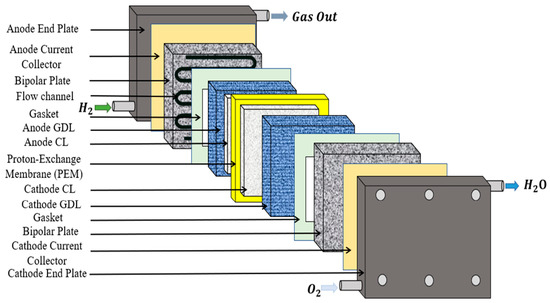
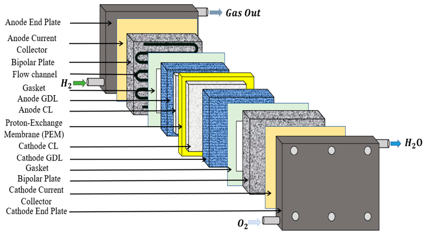
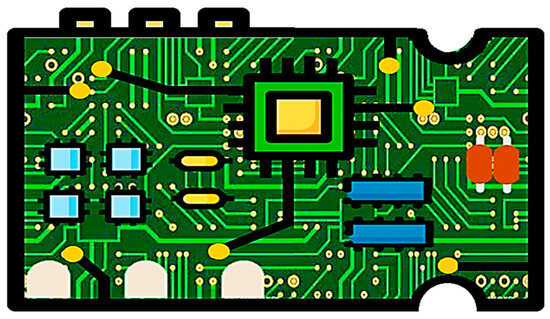
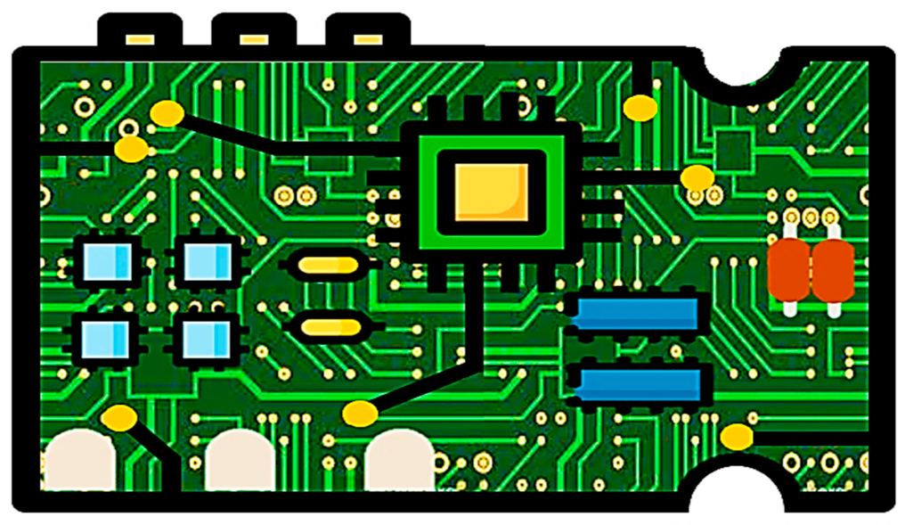
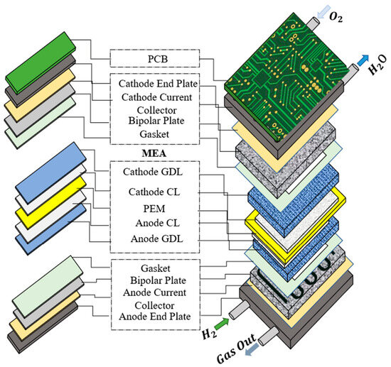
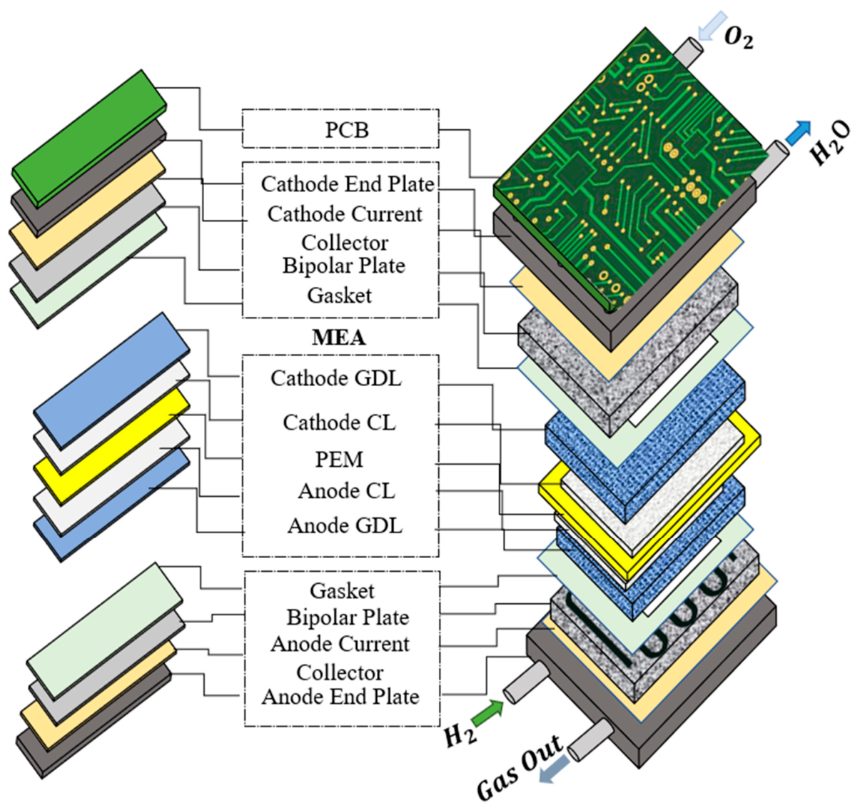
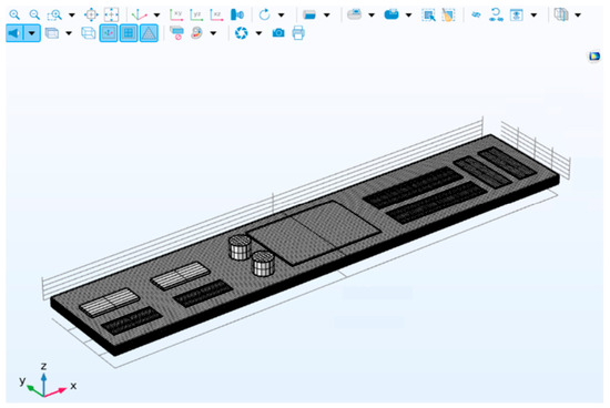
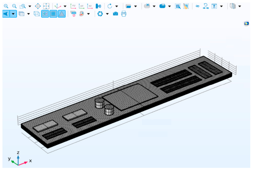
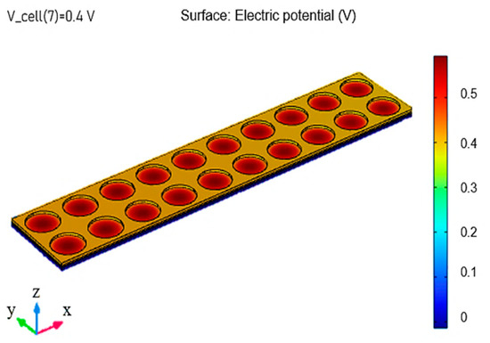
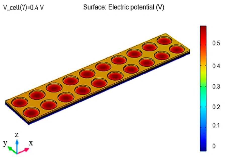
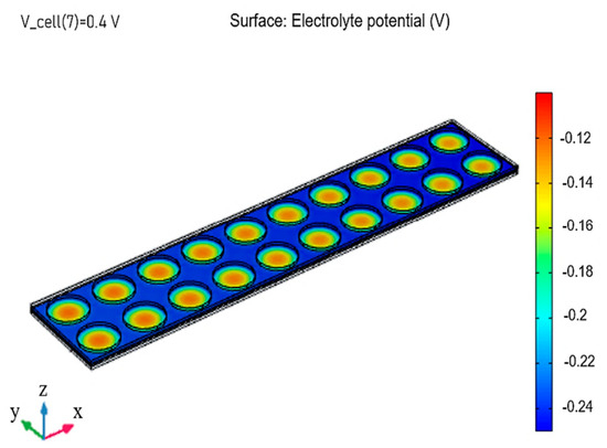
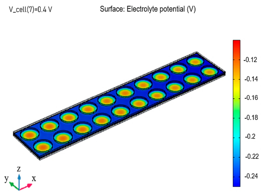
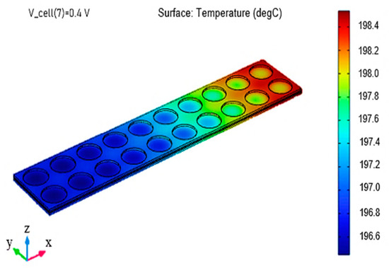
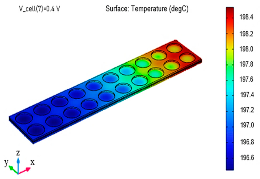
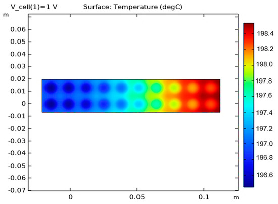
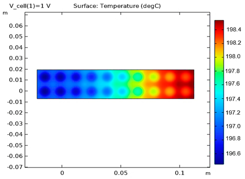
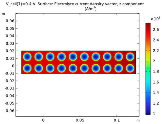
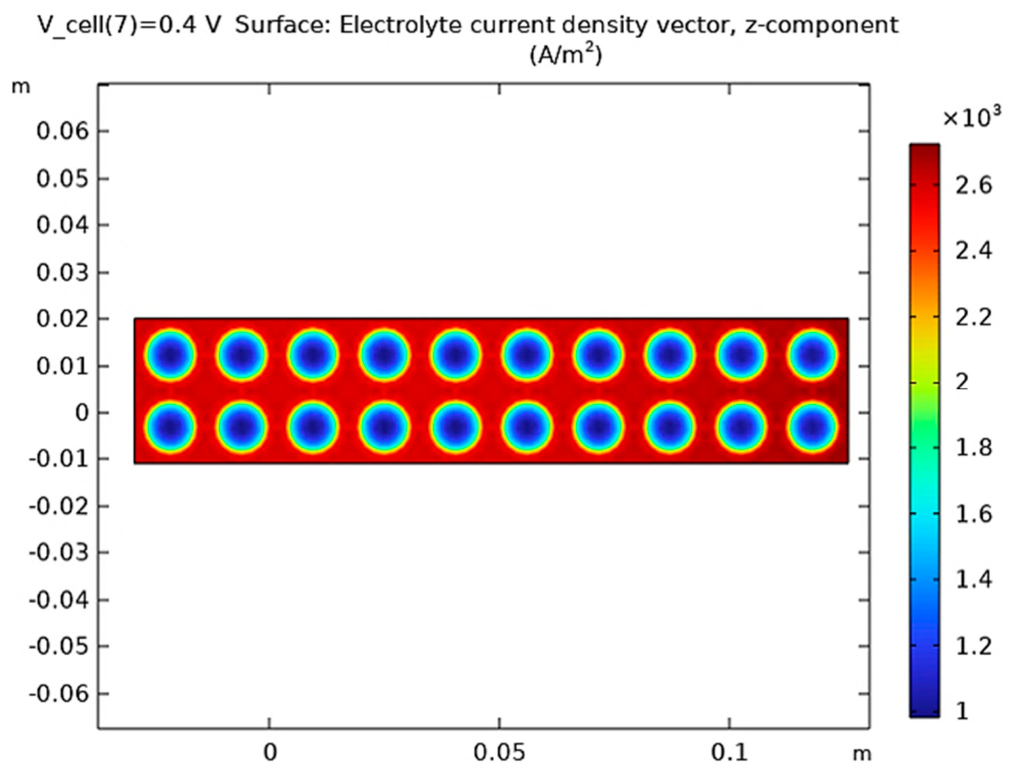
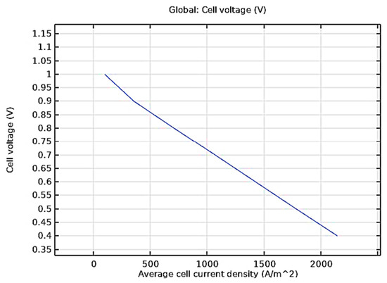
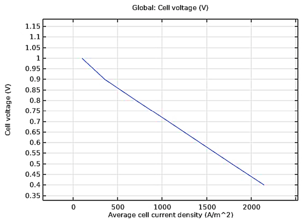
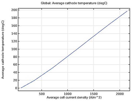
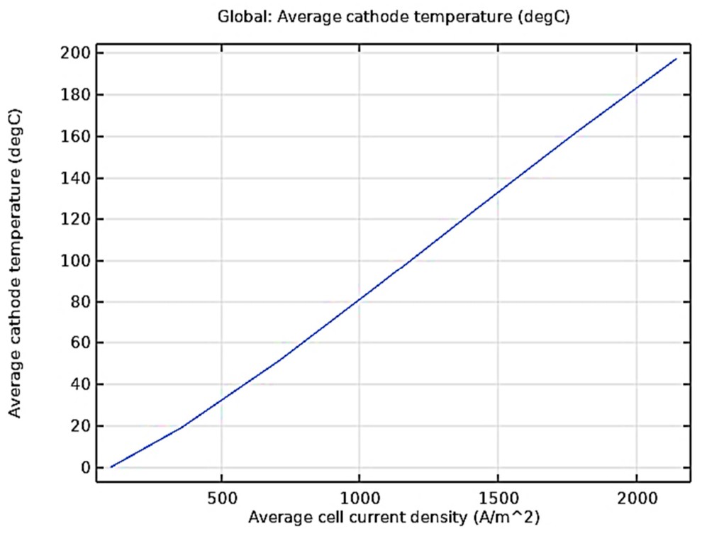
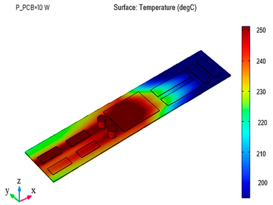
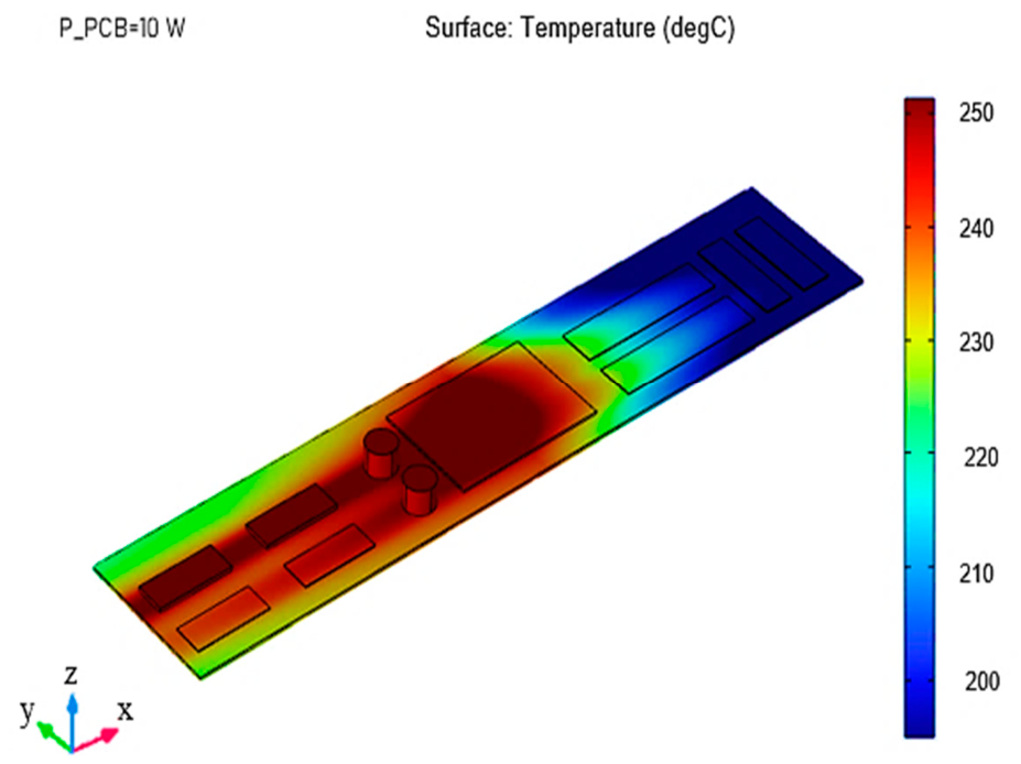
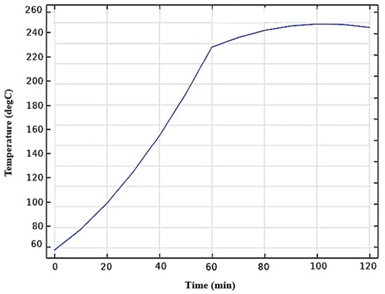
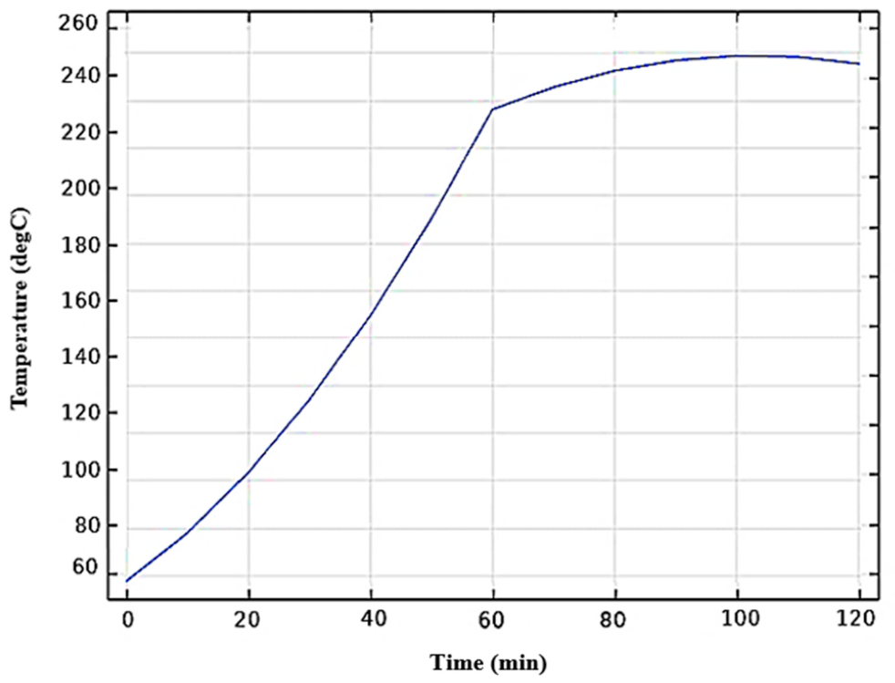
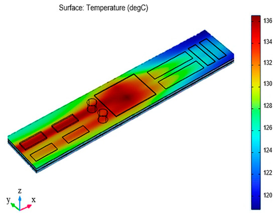
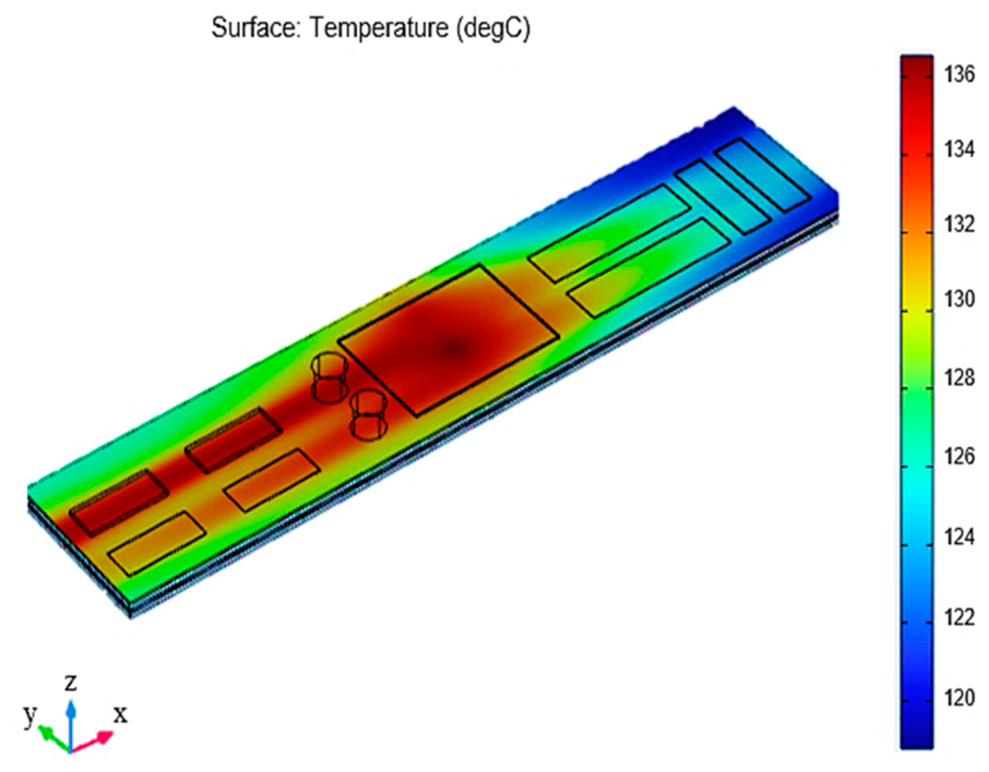
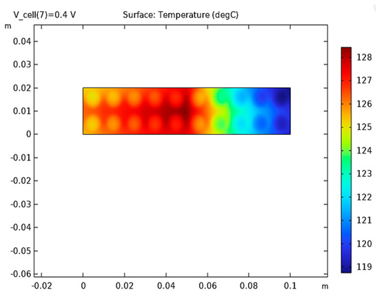
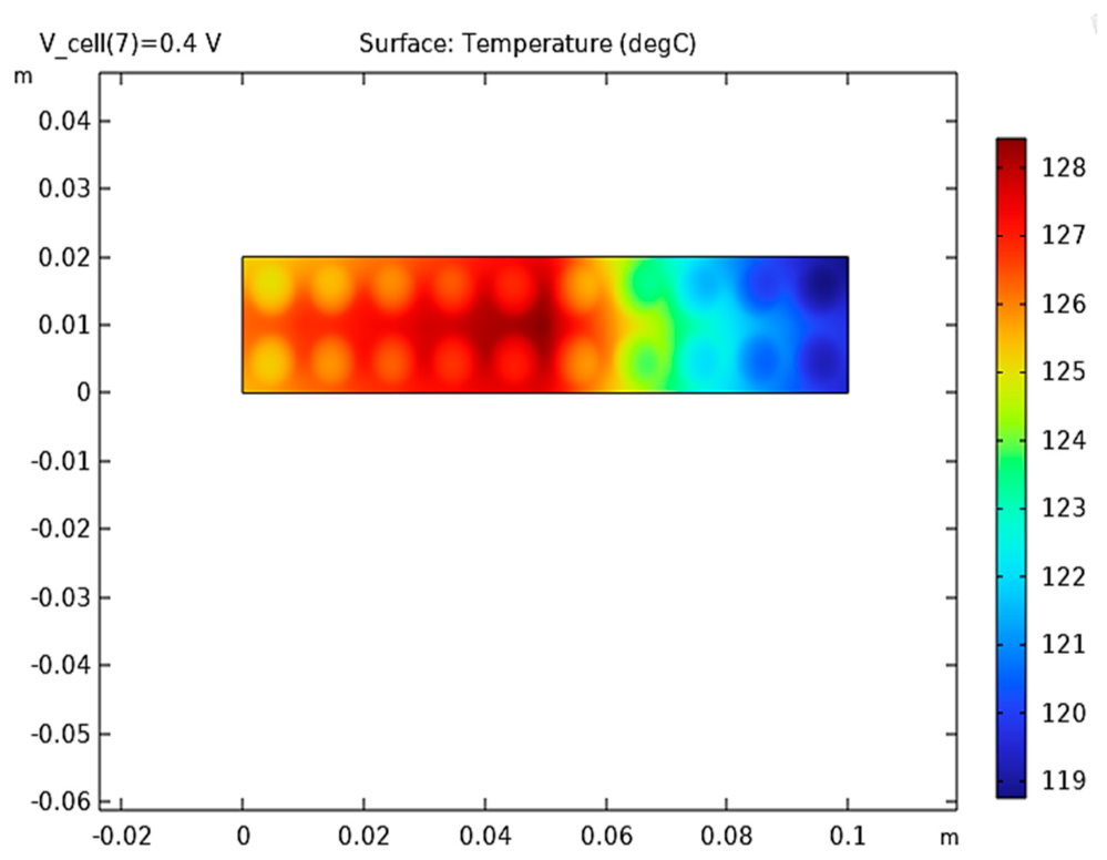
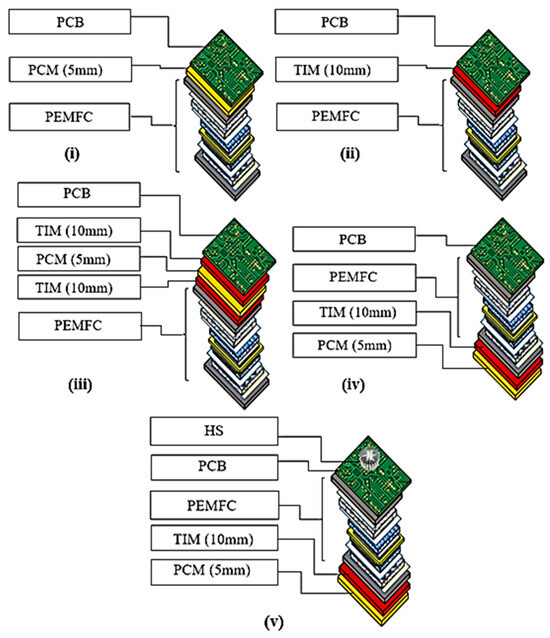
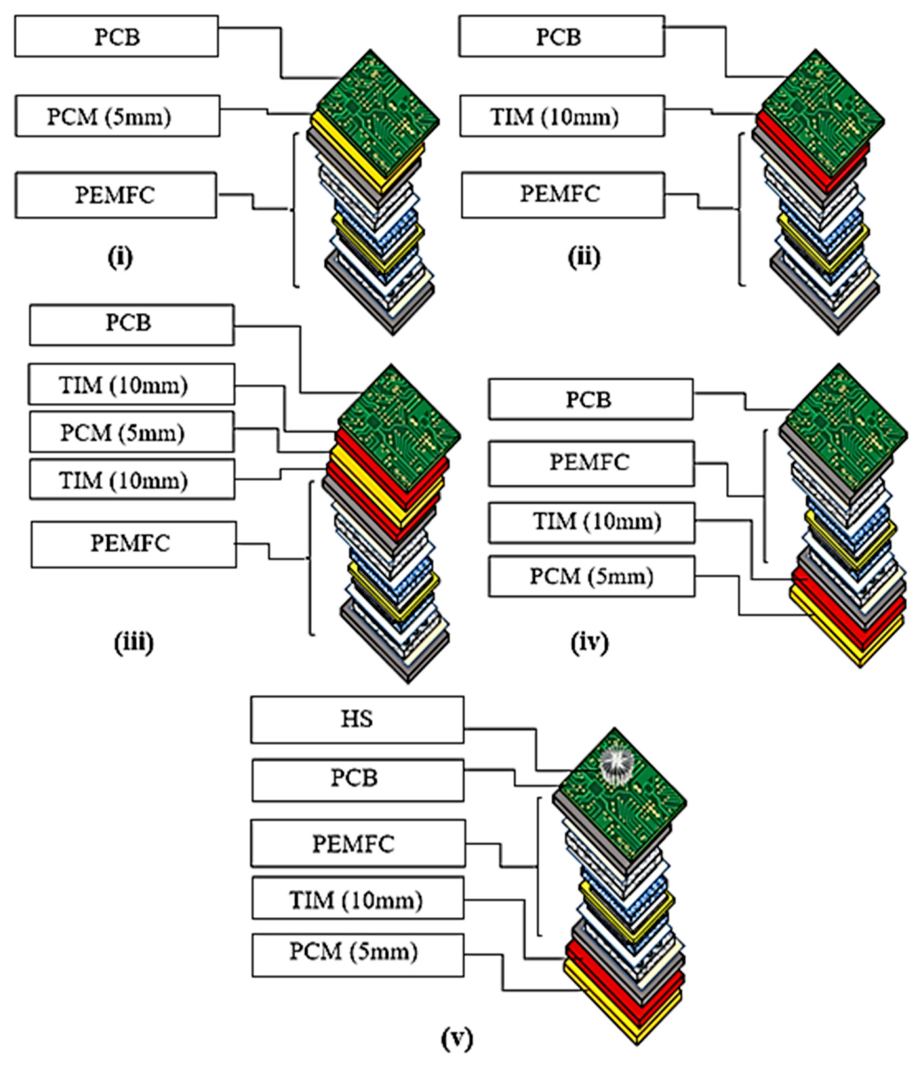
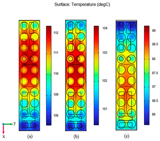
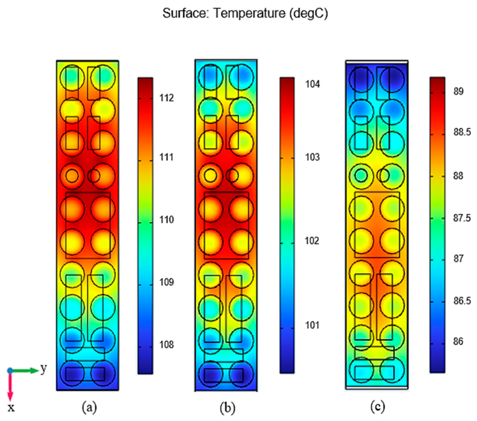
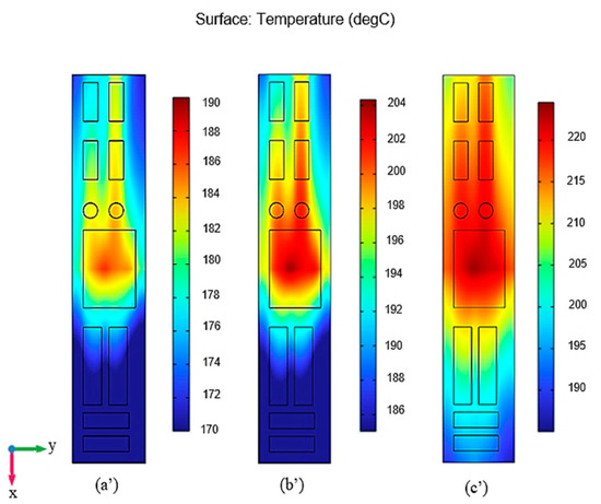
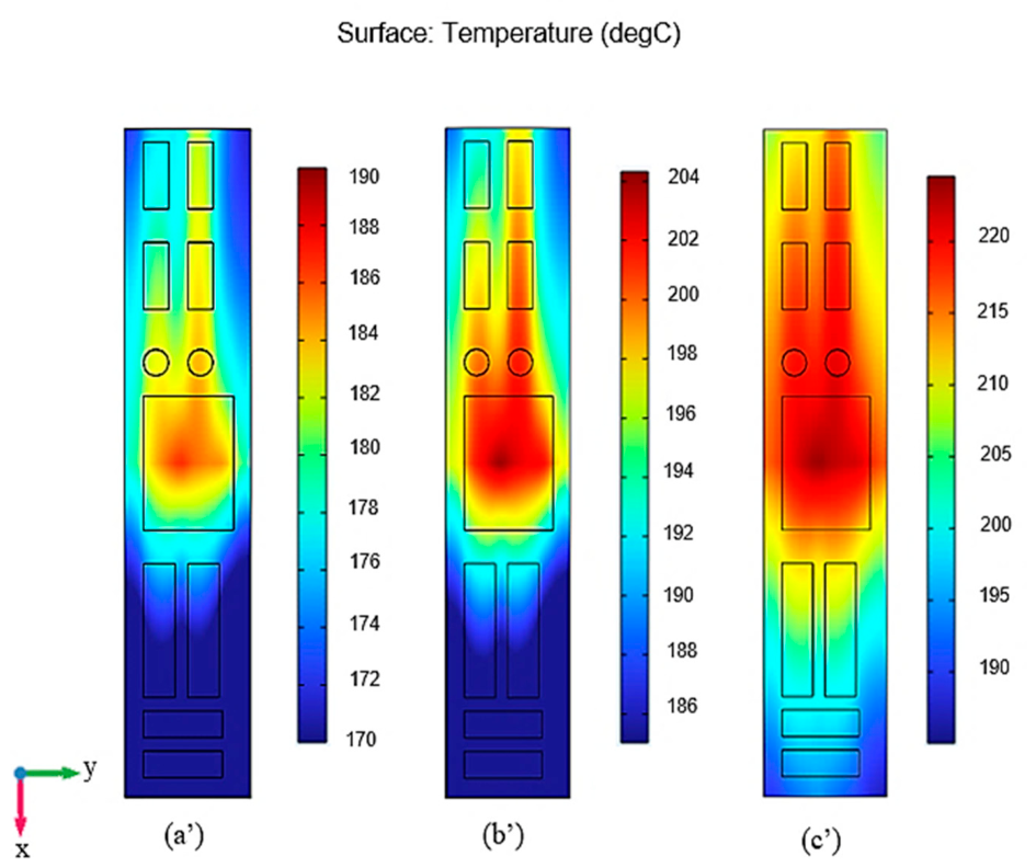
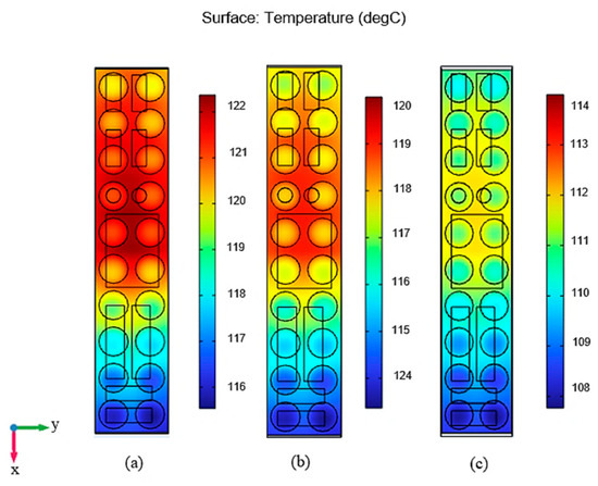
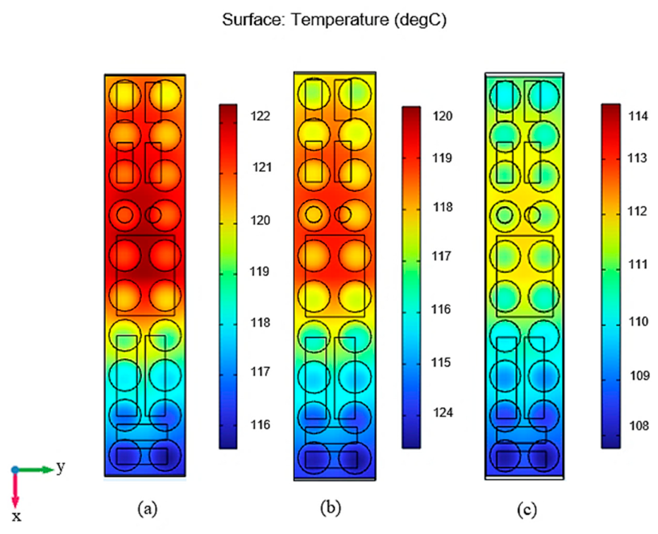
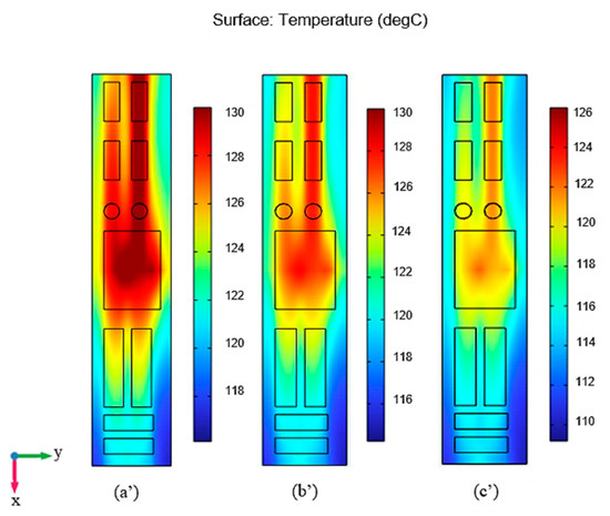
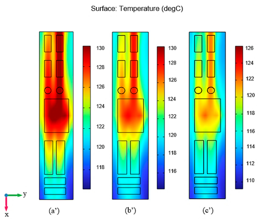
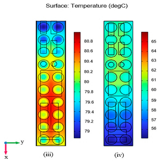
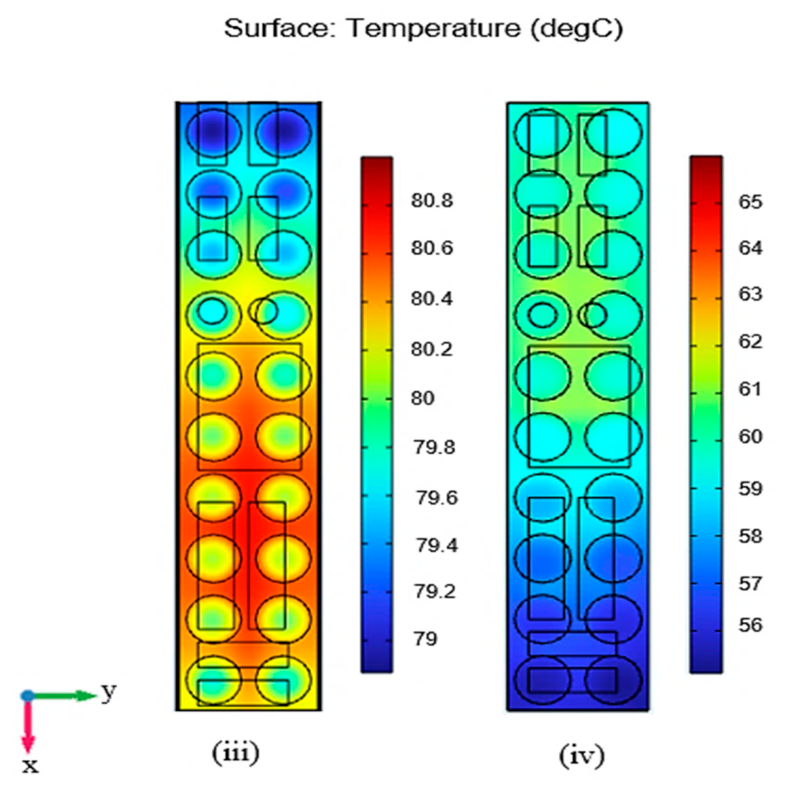
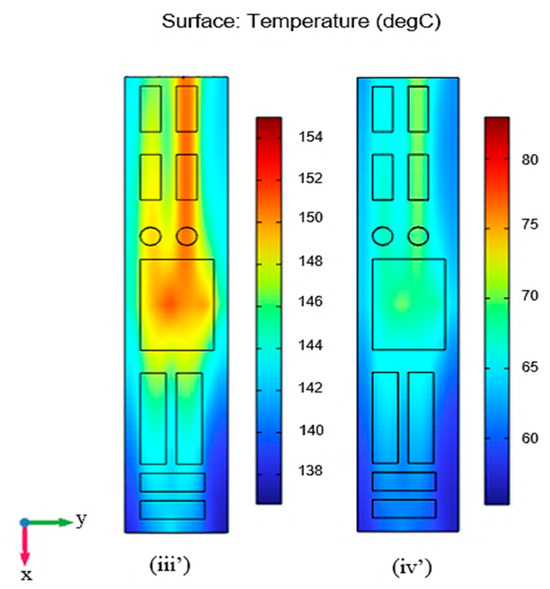
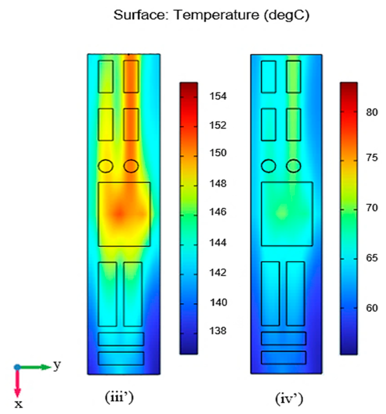
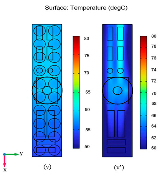
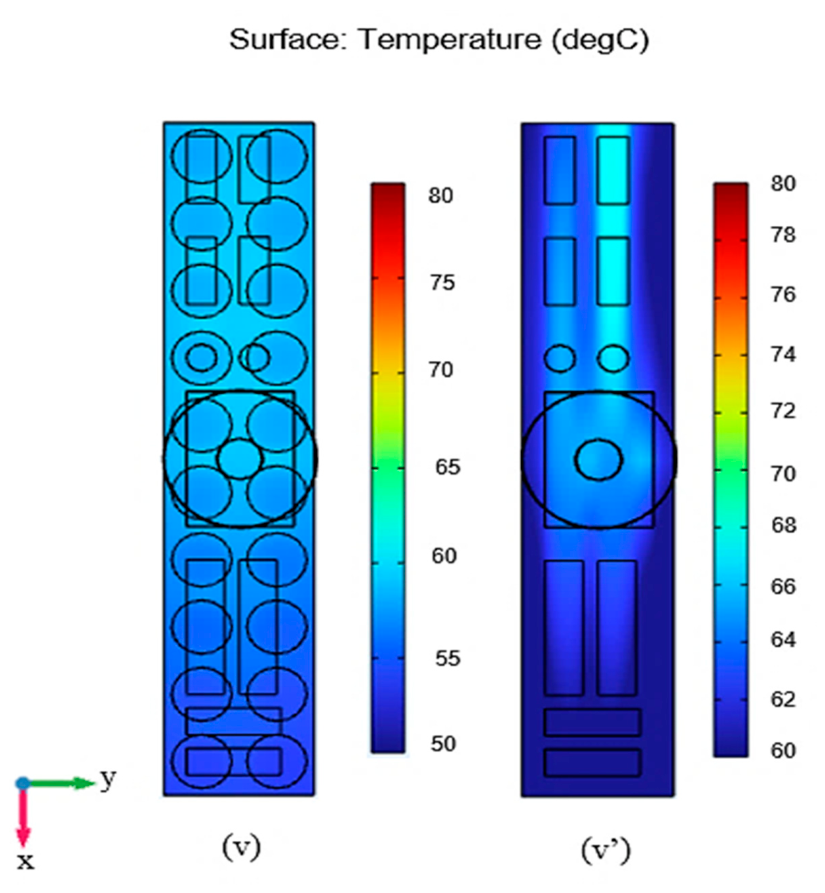
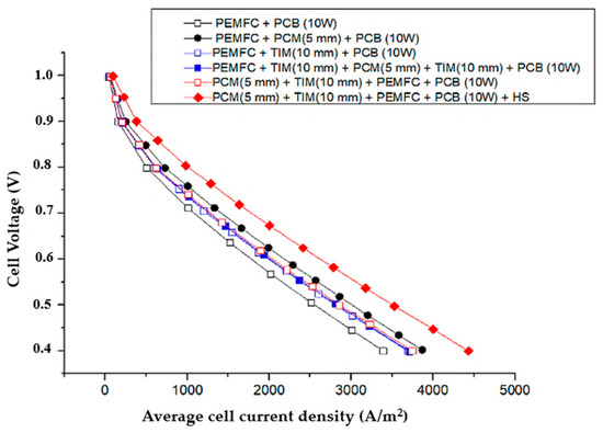
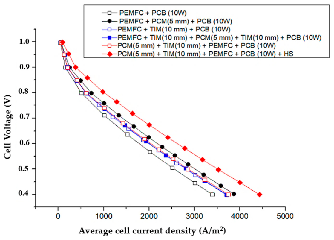
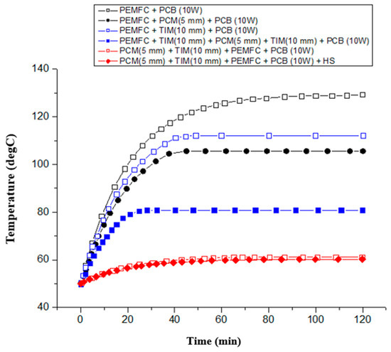
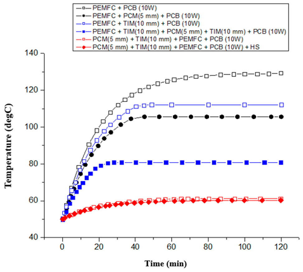
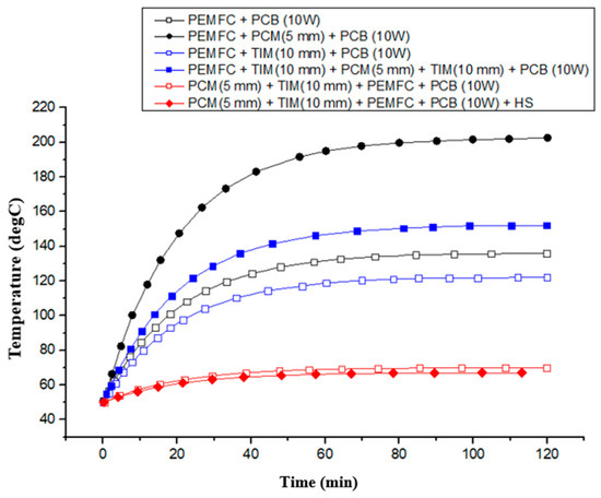
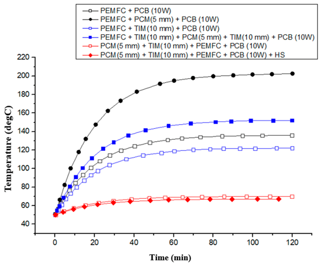

Disclaimer/Publisher’s Note: The statements, opinions and data contained in all publications are solely those of the individual author(s) and contributor(s) and not of MDPI and/or the editor(s). MDPI and/or the editor(s) disclaim responsibility for any injury to people or property resulting from any ideas, methods, instructions or products referred to in the content. |
© 2026 by the authors. Licensee MDPI, Basel, Switzerland. This article is an open access article distributed under the terms and conditions of the Creative Commons Attribution (CC BY) license.