


Abstract
Intuitive response and multi-objective control are well-known features of Finite Control Set Predictive Torque Control (FCSPTC). However, its implementation difficulty is a result of limitations such as high computations, strong model parameter dependency in control, and time-consuming tuning efforts for weighting factors in a cost function. Particularly, when FCSPTC is applied to a Multi-Level Inverter (MLI)-supplied motor drive, computation complexity is predominant. The proposed research work in this paper offers a new FCSPTC to dual two-level VSIs supplied for an Open Winding Permanent Magnet Synchronous Motor (OWPMSM) drive. The contributions of the proposed FCSPTC for the OWPMSM drive are the following. (i) Simplicity: There are fewer operational steps in control and limited evaluations with five prediction voltage vectors (VVs) out of 19, and a flux weighting-factor-less design is used by adopting a voltage cost function. (ii) Robustness: There is less parameter dependency in control through the involvement of stator resistance only. (iii) Switching frequency reduction: The application of an optimal switching state from the redundant switching states of optimal VVs is used to generate fewer switching state transitions, where the process is independent from the switching frequency weighting factor. According to theoretical and experimental findings, it is evident that the proposed FCSPTC technique operates effectively without the weighting factor and provides the above-stated features, resulting in an optimal response in flux, torque and current, switching frequency reduction, and low-complexity operation. The proficiency of the proposed FCSPTC technique is experimentally verified by comparing it with existing control schemes.
1. Introduction
In the field of electrical drives, the recent application of Finite Control Set Model Predictive Control (FCSMPC) has received a lot of interest due to its appealing features such as intuitive and multi-objective control [1]. Since FCSMPC operation is independent of the Pulse Width Modulation (PWM) stage, it delivers a faster dynamic response than Field-Oriented Control (FOC). Also, the elimination of hysteresis control-based look-up tables in its operation gives FCSMPC a better steady-state response than basic Direct Torque Control (DTC). Owing to these reasons, FCSMPC is preferably suitable for high-performance applications [2,3]. The most often used control methods [4] in FCSMPC are Predictive Current Control (PCC) and Predictive Torque Control (PTC). In PCC, the cost function solely considers the differences between the generated reference and predicted currents. Therefore, motor currents are control variables. However, with PTC, motor torque and stator flux are controlled directly. Due to its direct control nature, PTC gains torque response improvement over PCC [4,5].
Currently, the concept of PTC operation is extensively applied for various motor drive configurations. Some of the studies are presented to highlight advancements in PTC. In [6], PTC is used for a two-level Voltage Source Inverter (VSI)-fed Induction Motor (IM) drive, where the torque ripple reduction technique is utilized to derive the flux weighting factor. However, the procedure necessitates a thorough mathematical study and is reliant on machine parameters. In [7], the weighting factor is eliminated in the PTC operation of a two-level VSI-fed IM drive, where the optimization is provided through ranking-based objective functions. The same procedure of ranking analysis is adopted for a PTC-operated MLI-fed IM drive [8]. However, the computing complexity of this operation grows rapidly when it involves a higher number of Voltage Vectors (VVs) and multi-control objectives. A simple PTC for removing the weighting factor is presented in [9]. Initially, the torque control objective is evaluated for all VVs of the converter, and two optimal VVs are chosen to assess the flux control objective in the final stage. Thereby, final stage optimization provides a suitable VV for motor drive operation. In [10], improvements are made to PTC [9] by selecting three optimal VVs in the first stage instead of two VVs. However, the individual assessment of torque and flux control objectives in a sequential manner may lead to loss of unified optimal control. This problem is stated in [11], where modified sequential PTC is proposed with minimum cross-error criteria. However, the operation involves the application of ranking methodology, which further increases control complexity and computation time. In particular, this effect becomes more significant when implemented for MLI-fed motor drives due to the increase in VV number. In [12], to eliminate the weighting factor in PTC, parallel optimization of flux and torque control objectives with predefined error boundaries is adopted. However, the operation relies on error boundary adjustments and increases control complexity. In [13], the top three optimal VVs of flux and torque are identified, and the common VV is applied for combined optimal flux and torque control without the weighting factor in PTC. To enable weighting factor optimization in PTC, multi-criteria decision analyses such as TOPSIS [14], VIKOR [15], and grey relational analysis [16] are incorporated. Further, the multi-objective genetic algorithm [17], fuzzy [18], and artificial neural network [19] techniques are recognized for their ability to solve the weighting factor optimization issue in PTC. To eliminate the flux weighting factor, Refs. [20,21,22] propose a single stator flux vector control objective for simultaneous flux and torque control. Similarly, Refs. [23,24] propose a voltage cost function for combined flux and torque control in PTC. However, the motor model parameters are used in the reference flux computation. If any mismatch occurs from actual parameter values, the correctness of reference flux computation is affected. As a result, reference VV generation is also affected and degrades overall motor drive performance.
In medium/high voltage traction drives, using MLI instead of a two-level VSI benefits voltage and current Total Harmonic Distortion (THD) reduction, common mode voltage reduction, and lower voltage stress on components. Many MLI-supplied motor drives are presented in the literature [25,26,27,28,29]. Apart from all the possibilities, a dual VSI-supplied Open Winding Permanent Magnet Synchronous Motor (OWPMSM) drive is stated as one of the best choices owing to its several benefits [30,31,32]: (i) PMSM as a part of an electrical drive facilitates notable features such as high-power density and efficiency, simple structure. (ii) Three phase Open Windings (OW) of PMSM supplied from dual two-level Voltage Source Inverters (VSIs) enable a simple MLI circuit with ready accessibility, greater voltage space vector generation, inclusion of hybrid sources, and fault tolerance. All these supporting benefits encourage implementation of OWPMSM drive in vital electrical drive applications such as Electric Vehicles (EVs) and its operation through PTC. In [33], OWPMSM drive is used to function EV power train, and PTC based on ranking analysis is applied without weighting factors. However, the process consumes more computational time. The same difficulty is faced in [34], where a weighting factor independent PTC for OWPMSM drive is performed through individual assessment of flux and torque control objectives to find optimal VV.
Important obstacles in PTC operation are noted from the above-mentioned literature: (i) Control reliance on weighting factor and its heuristic calculations. (ii) Control computation complexity. (iii) Control dependency on parameters strongly. This research proposes a simpler PTC that does not employ a weighting factor to address the aforementioned concern. The proposed PTC optimizes the torque and flux responses together using just the voltage cost function, eliminating the need for a weighting factor. The proposed PTC operation is based only on stator resistance and requires extremely few calculation steps. As a result, there is reduced parameter dependence and computation complexity. Furthermore, by suitably using the optimum VV’s possible redundant switching state, switching frequency is reduced. All these enhanced features develop a simple, robust, and weighting-factor-less PTC for optimal OWPMSM drive operation.
To the best of the author’s knowledge, most of the literature lags in the development of simple, robust weighting-factorless PTC along with switching frequency minimization for OWPMSM drive operation. Upon considering this, enhanced PTC for OWPMSM drive is developed in this paper, and its proficiency is validated through comparisons with existing PTC. The following is the organization of this paper: Section 2 presents the OWPMSM drive’s mathematical model. The PTC algorithms, both basic and proposed, are discussed in Section 3. In Section 4, the experimental findings of both existing and proposed PTCs are shown. Section 5 concludes this paper.
2. Mathematical Model of OWPMSM Drive
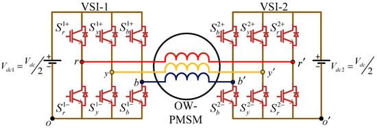
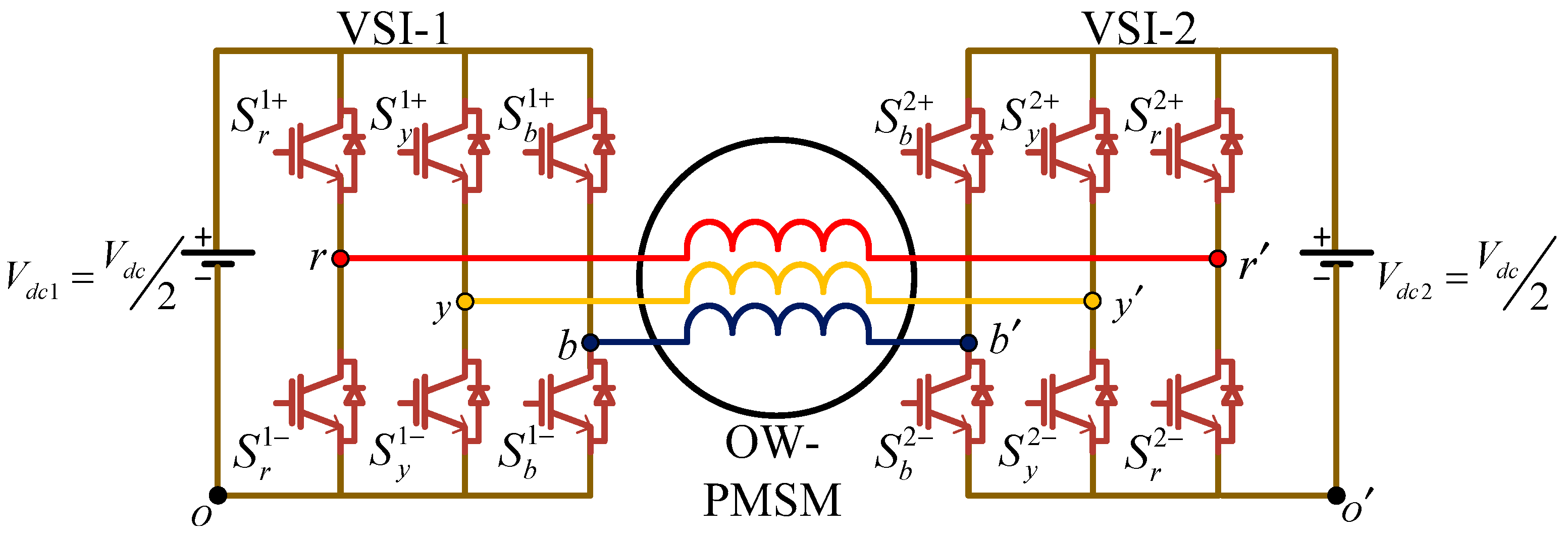
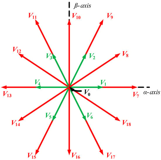
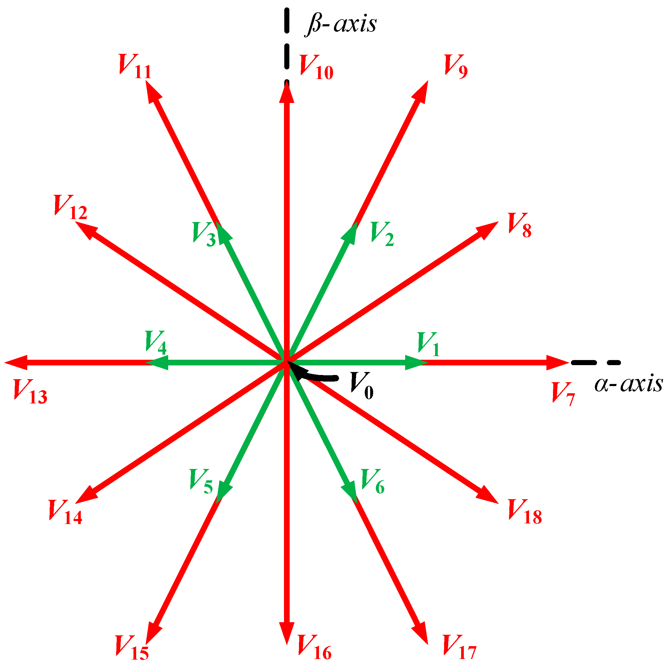
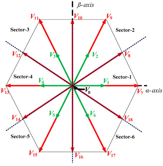
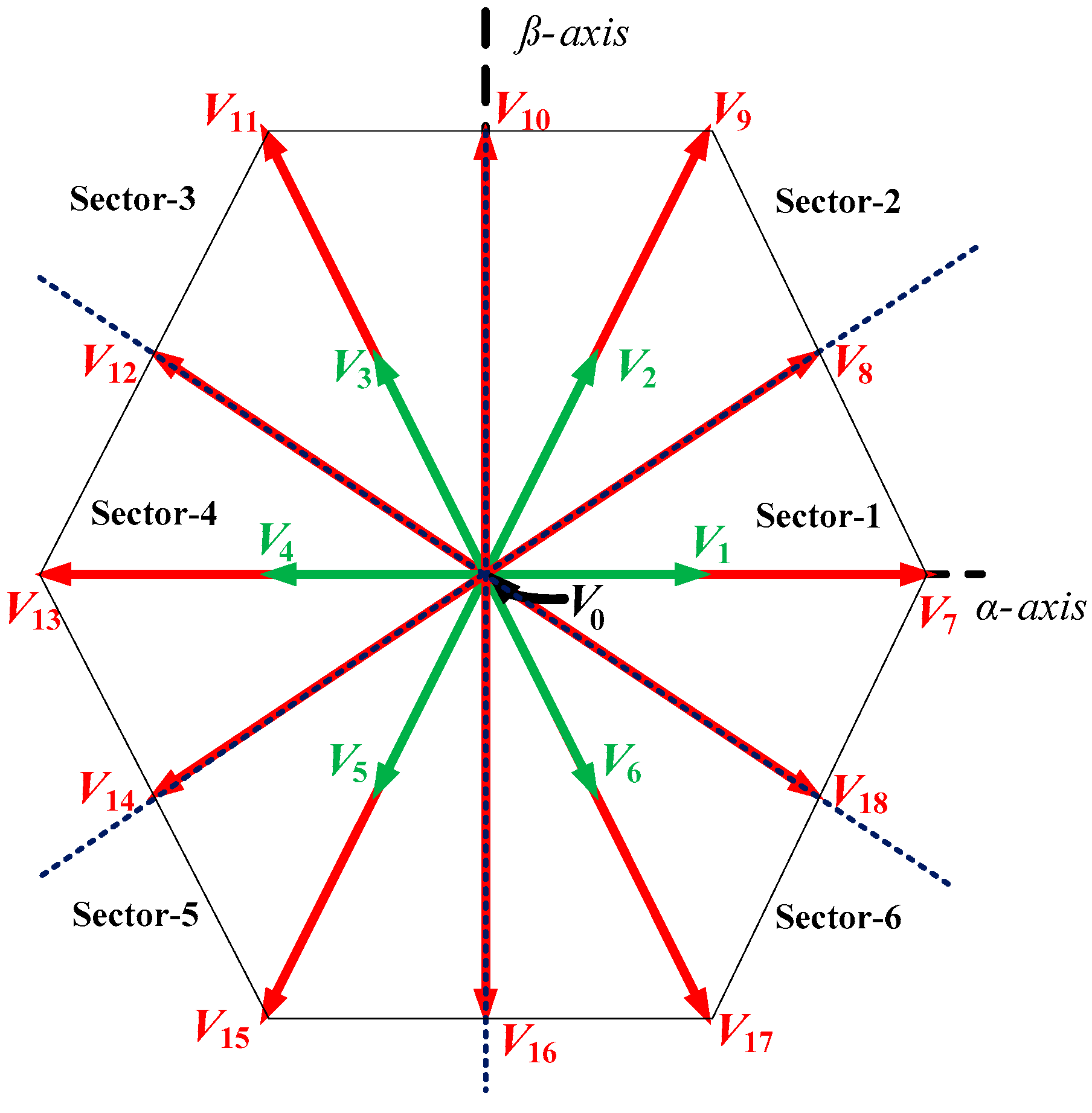
As displayed in Figure 1, the circuit of a dual two-level VSI fed OWPMSM drive has six legs with a total of 12 switches. The pulse to switch is indicated with the symbol ‘S’, where (, , , , , ) are connected to top switches and its complimentary (, , , , , ) are connected to bottom switches. During dual two-level VSI operation with equal DC link voltages of magnitude (i.e., Vdc1 = Vdc2 = Vdc/2), the generated pole voltages of dual VSIs are given by (1) and (2). In the stationary αβ reference frame, voltage space vectors of VSI-1 and 2 are provided by (3) and (4), respectively. From these, the net voltage space vector is presented as (5). For each two-level VSI, there are eight switching states. This means a total of 64 switching states are possible for dual VSI operation. Considering the switching states of minimum common-mode voltage (CMV) (6), (1)–(5) are evaluated, and calculated net voltage space vectors are listed in Table 1. From this, 19 unique VVs are identified and plotted in the αβ plane as shown in Figure 2. These VVs are termed as prediction VVs and involved in PTC function for OWPMSM drive.
Figure 1.
Circuit of dual two-level VSI supplied OWPMSM.
Table 1.
VV realization of dual two-level VSI.
Figure 2.
VV distribution of dual two-level VSI in αβ plane.
The stator voltage of OWPMSM in space vector form is specified in the stationary αβ reference frame as (7). In (7), the indicated terms are space vectors such as stator current- and stator flux- (8). , denotes stator resistance and inductance. In (8), is a rotor flux magnitude referred to the stator through multiplication factor , where is the rotor angle. The motor torque generation is provided by (9), where it is a function of stator current and flux vectors and number of poles P.
In (7), the stator flux () is provided by (8).
In (10), the relation between motor () and load () torque is given, where is moment of inertia and is mechanical speed in rad/s. The presented dynamic Equations (7)–(9) are discretised to apply in PTC operation of OWPMSM drive.
3. PTC of OWPMSM Drive
3.1. Basic PTC of OWPMSM Drive
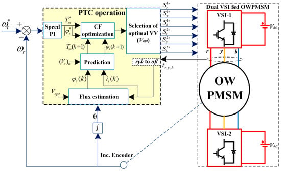
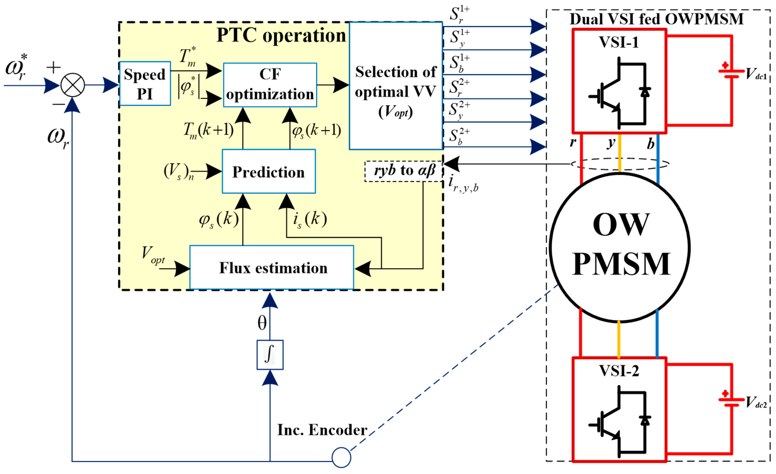
The inputs to PTC operation (as depicted in Figure 3) are reference motor torque () and flux (), stator current () and net DC link voltage () of dual VSIs. The output of the speed PI controller generates to gain minimum error between actual () speed and reference () speed. PMSM-rated flux is given as . The dual VSI’s net DC link voltage and motor phase currents can be directly sensed. Considering this input data, the basic PTC of OWPMSM drive operates in three key stages as described below:
Figure 3.
Basic PTC operation of dual two-level VSI fed OWPMSM drive.
(i) Flux Estimation: Estimating the stator flux at the present sample state (k) is essential in PTC. The stator flux estimate is given as (11) when Euler’s discretization is used for (7), where is the present optimal VV, is the flux vector at the previous sample, and TS is the sample time.
(ii) Prediction of control variables: Torque and flux are the two primary control variables in PTC. As a result, they are involved in the prediction process. Prediction of control variables at the (k + 1) state is attained by involving possible VVs of dual VSI (i.e., 19 prediction VVs) and control variables at the (k) state. Therefore, formulations of current and flux predictions are given by (12) and (13). Using (12) and (13), torque prediction is provided by (14). Finally, 19 values of flux and torque predictions are gained. Subscript n denotes the number of predictions.
(iii) Cost function evaluation: The cost function (CF) described in (15) is commonly employed for basic PTC operation [35] to pick the optimal VV, which minimizes torque and flux errors. In (15), the magnitudes of reference torque and flux are referred as and . These reference values are compared with their respective prediction values ( and ). The VV that generates the lowest CF value with the smallest control error between the reference and prediction is considered to be the best for control application in the next sample time.
The only configurable parameter in CF (15) during PTC implementation is the weighting factor (). The choice of weighting factor has a significant influence on motor drive performance. Basically, considering nominal stator flux () and torque () values, weighting factor (16) is designed. However, to improve the drive’s performance in real-time applications, this weighting factor must be fine-tuned further.
3.2. Proposed PTC of OWPMSM Drive
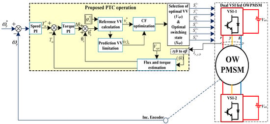
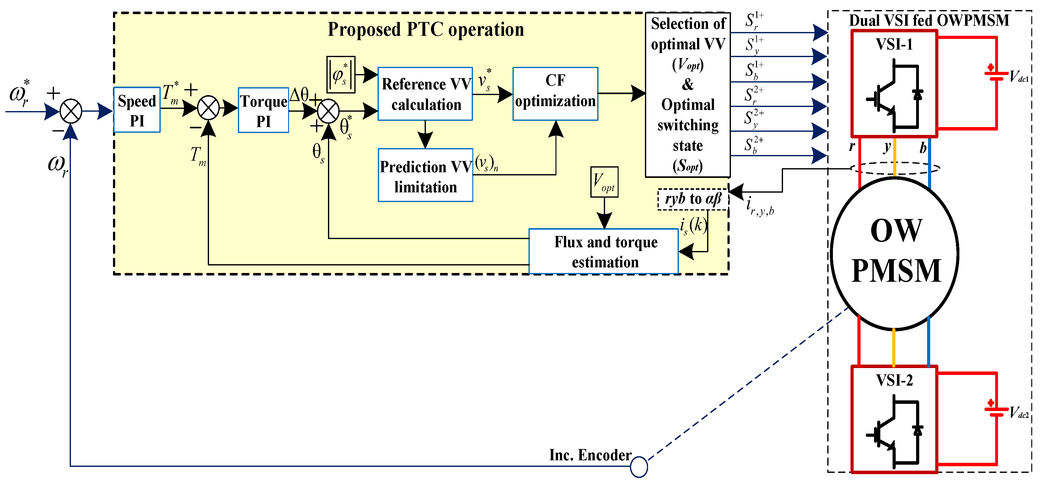
From the above discussions (Section 1 and Section 3.1), it is evident that PTC operation is directly reliant on weighting factor choice in CF. The manual adjustment of is quite time consuming in order to achieve acceptable PTC performance. Various strategies have been offered in the literature to optimize or eliminate the weighting factors in PTC (as discussed in Section 1). However, these modified PTC strategies create extra computational burden. Besides this, control performance degrades with model parameter mismatch. To address these issues, this research paper proposed a simple and robust weighting-factor-less PTC for OWPMSM drive. The following are contributions of this research paper to enhance PTC for dual VSI supplied OWPMSM drive: 1. Design of robust weighting-factor-less operation for optimal flux and torque control. 2. Simple control operation having low computational complexity. 3. Switching frequency reduction. Considering these contributions, the proposed PTC is built as shown in Figure 4, and its detailed analysis is discussed below:
Figure 4.
Proposed PTC operation of dual two-level VSI fed OWPMSM drive.
- (i).
- Design of robust weighting-factor-less operation for optimal flux and torque control:
The basic CF (15) is replaced with voltage CF as (17) to achieve weighting-factor-less operation for flux and torque control. In (17), indicates reference VV to attain unified flux and torque control.
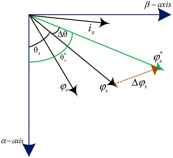
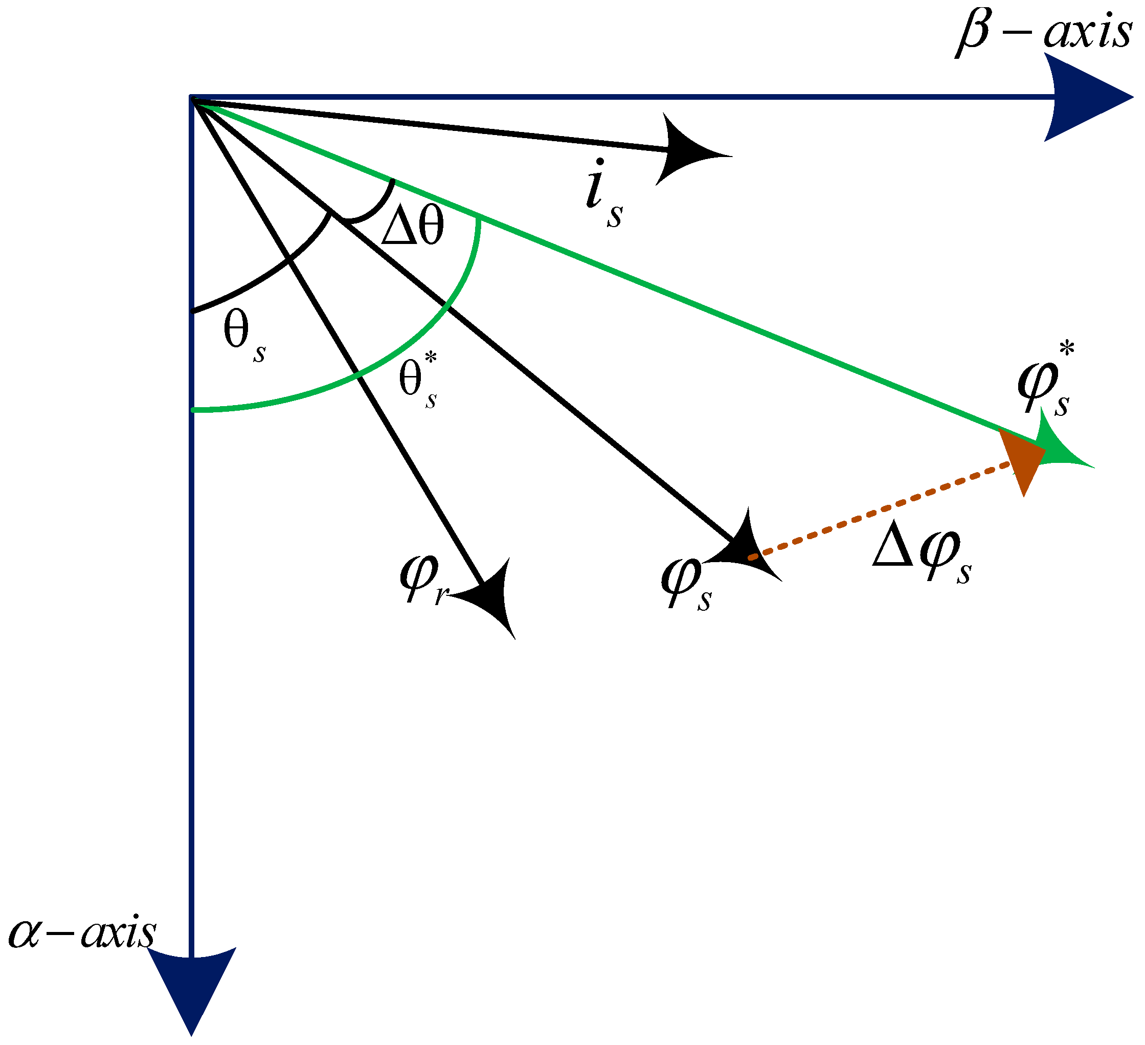
Steps to generate reference VV are listed below, and the analysis in phasor form is represented in Figure 5.
Figure 5.
Phasor form analysis.
Step 1: To maintain minimum error between reference and actual speeds, find required torque reference () from speed PI output.
Step 2: Actual motor torque is estimated from Equations (7) and (9) to compare with reference torque. Thus, torque error is fed to torque PI to generate the required change in stator flux angle () and minimize torque error.
Step 3: The addition of the actual stator flux angle () and obtained change in stator flux angle () provides the reference stator flux angle as (18). PMSM-rated stator flux magnitude is assigned to reference flux . Therefore, the generated reference stator flux angle and magnitude deliver the reference stator flux vector ().
Step 4: By equating the reference stator flux vector to the next sample (k+1) stator flux vector, the reference VV is determined, which is given by (19) and (20).
Since reference VV is configured through reference flux and torque values, its application in the control process guarantees an optimal flux and torque response. To realize reference VV through possible discrete VVs of dual VSI, CF (17) is evaluated. In (17), all the possible prediction VVs are compared with reference VV to identify optimal discrete VV which provides minimum error.
Thus, the obtained optimal discrete VV is applied for the next sample time for better control of flux and torque.
From the above-discussed control steps of reference VV generation and Figure 5, it is evident that the proposed PTC operation involves only model resistance parameter. No complex mathematical equations with strong parameter dependency are seen in the proposed PTC evaluation. Therefore, a design goal of robust weighting-factor-less operation for optimal flux and torque control is achieved in proposed PTC.
- (ii).
- Simple control operation having low computational complexity:
As reference VV is predetermined, its location is utilized to limit prediction of the VV number. To accomplish this, the VV plane is partitioned into six sectors with 60° angles as presented in Figure 6. Based on angle information of reference VV, the sector location of reference VV is identified. From Figure 6, it is evident that each sector is allocated with five discrete VVs. These VVs are only present in the vicinity of reference VV in a sector. Owing to this, limited prediction VV sets having five possible discrete VVs are formed for each sector as listed in Table 2.
Figure 6.
Partitions of VV plane.
Table 2.
Prediction VV limitation.
Based on sector information, a suitable limited prediction VV set is passed for CF (17) evaluation. This implies that optimal VV is gained by evaluating CF (17) only 5 times with a limited prediction VV set instead of 19 times. Therefore, a simple control operation having low computational complexity is attained for the proposed PTC operation.
- (iii).
- Switching frequency reduction:
From Table 1, redundant switching states pertaining to CMV not more than Vdc/6 in magnitude are observed for the VV application. Among the possible redundant switching states of determined optimal VV, the appropriate one is selected for dual VSI operation to gain minimum state transitions. This can be ensured from (21), where possible redundant switching states (Sr) of optimal VV are compared with previously applied switching state (Sopt(k − 1)). The minimum value of (21) provides an optimal VV switching state to gain minimum state transitions, and it is finally considered as the optimal switching state to apply for dual VSI. As a result, the proposed PTC of OWPMSM drive achieves switching frequency reduction by minimizing total switching state transitions.
In (21), j implies VSI leg number, and r is the redundant switching states number.
The above theoretical analysis validates the contributions of the proposed PTC, such as the design of robust and weighting-factor-less operation to gain optimal flux and torque response, low control complexity, and switching frequency reduction. Hence, an enhanced OWPMSM drive operation with the proposed PTC is achieved.
3.3. Comparative Analysis
- A.
- Existing weighting-factor-less PTC approaches:
In reference stator flux vector-based PTC, flux prediction calculations need to be processed for the available prediction VVs, which are thereby supported for stator-flux vector-based weighting-factor-less CF evaluation. This additional flux prediction calculations impose a computational burden. Moreover, the reference stator flux generation in PTC [21,22] operation elucidates that the process is dependent on motor parameters such as resistance, rotor flux, and inductance values.
The research is also extended to reference VV-based PTC, where the PTC [23] operation involves reference VV generation. From [23], it is evident that the process of reference VV generation includes strong parameter dependency with the involvement of motor parameters (rotor flux, stator resistance, and inductance) along with rotating-reference frame transformation. Similarly, the recent studies [36,37] are operated with reference VV generation, where it has strong dependency on motor parameters such as stator resistance, inductance, and permanent magnet flux. Thereby, the task of online parameter rectification is carried out to address the issue.
The even-handed sequential optimization-based weighting-factor-less PTC proposed in [11] still requires flux, current, and torque prediction calculations for the available prediction VVs, which are thereby supported for sequential CF evaluation. In particular, this control when operated for OWPMSM drive, owing to the large prediction VVs number, the control complexity is predominant with a remarkable computational burden. Moreover, this control process is strongly dependent on all the motor parameters.
- B.
- Distinction between the proposed method and existing weighting-factor-less PTC approaches:
Unlike existing stator-flux vector-based PTC, the proposed method deals with direct voltage CF evaluation without intermediate flux prediction calculations. Moreover, superior to the existing VV-based PTC method, where the reference VV generation has a strong motor parameter dependency, the proposed control method features a simplified reference VV generation process that entirely excludes both stator inductance and permanent magnet flux. This is clearly evident from Section 3.2, where the absence of both parameters demonstrates the control’s robustness.
Following the above-mentioned discussion, the key novelty lies in the realization of preferred limited VVs from the total available 19 VVs of the OWPMSM drive. Thus, the proposed candidate VV screening (as discussed in Section 3.2) for OWPMSM drive ensures a limited effective prediction VV set, which is thereby supported for voltage CF (17) for a limited number of evaluations. From these limited evaluations, the optimal VV is chosen for the control operation of the OWPMSM drive.
In addition, the control algorithm is tactically designed to minimize switching frequency without affecting the performance of the OWPMSM drive. In the traditional way, the same optimal VV is forced to be selected for the consecutive sampling periods, which impacts switching frequency reduction and, thereby, a rise in current THD affecting overall performance of the motor drive. However, in the proposed PTC, the switching frequency reduction is attained by the application of optimal switching state from the redundant switching states of optimal VV to generate fewer switching state transitions, where the process is independent from switching frequency weighting-factor.
From all the above-mentioned discussions, the novelty of overall control structure for enhanced OWPMSM drive operation is summarized as follows: (i) Simplicity: Fewer control-operational steps and limited evaluations with 5 prediction Voltage Vectors (VVs) out of 19, a flux weighting-factor-less design by adopting a voltage cost-function. (ii) Robustness: Less parameter dependency in control through involvement of only stator resistance. (iii) Switching frequency reduction: Application of optimal switching state from the redundant switching states of optimal VV to generate fewer switching state transitions, where the process is independent from switching frequency weighting-factor.
Finally, all these discussions validate the development of simple and robust weighting-factor-less PTC for enhanced OWPMSM drive operation.
4. Results and Discussion
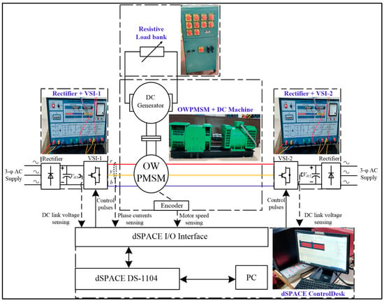
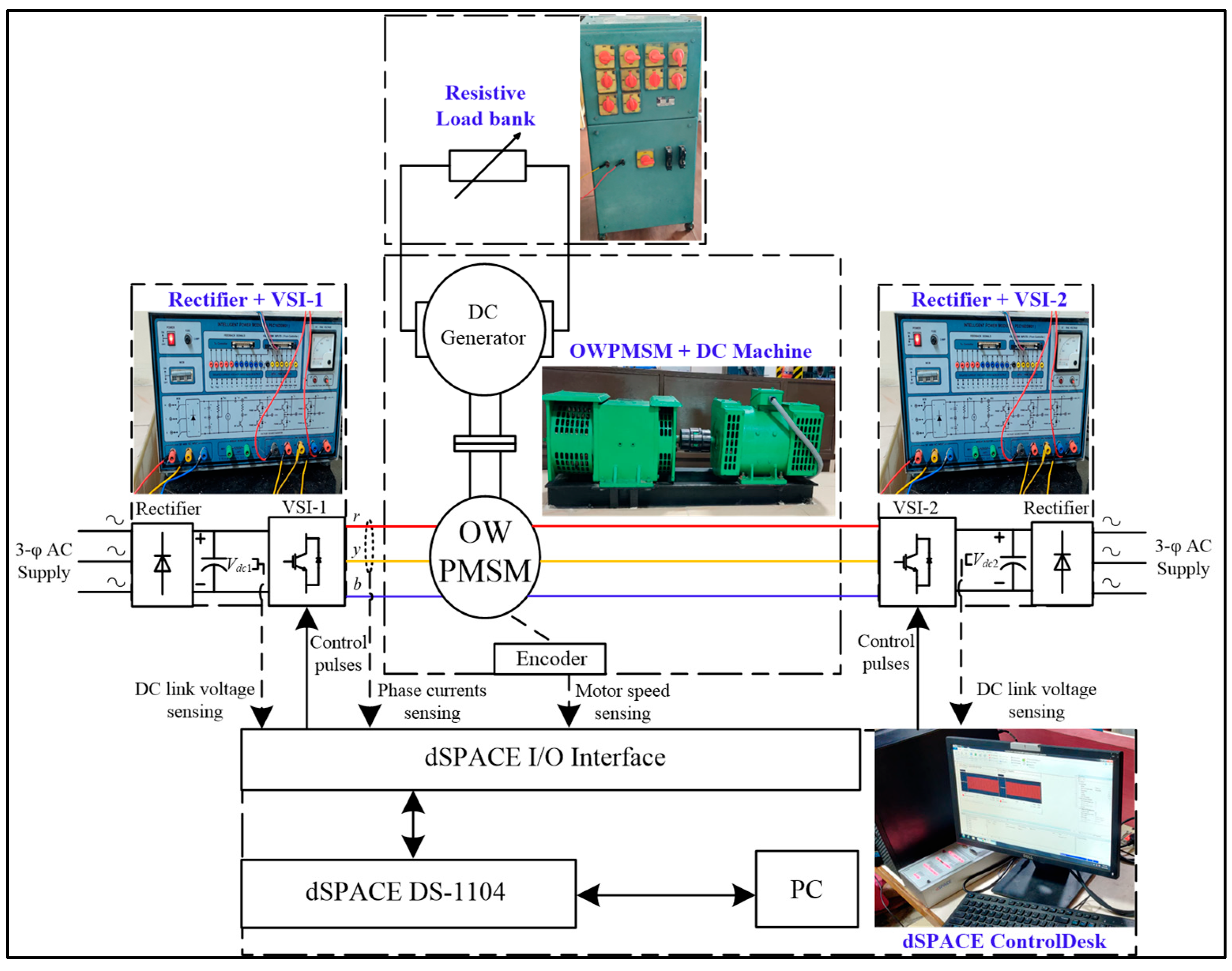
The experimental platform for the OWPMSM drive is developed, and dSPACE-1104 (Chennai, India) is employed as the control processor in order to evaluate the performance of the proposed PTC technique and validate its usefulness. On this experimental platform depicted in Figure 7, the existing PTC techniques and the proposed PTC technique are compared.
Figure 7.
Experimental layout of the OWPMSM drive.
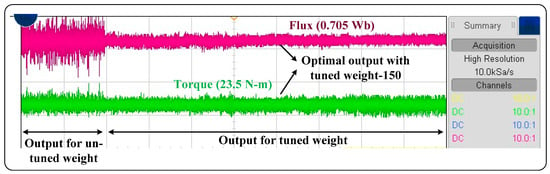
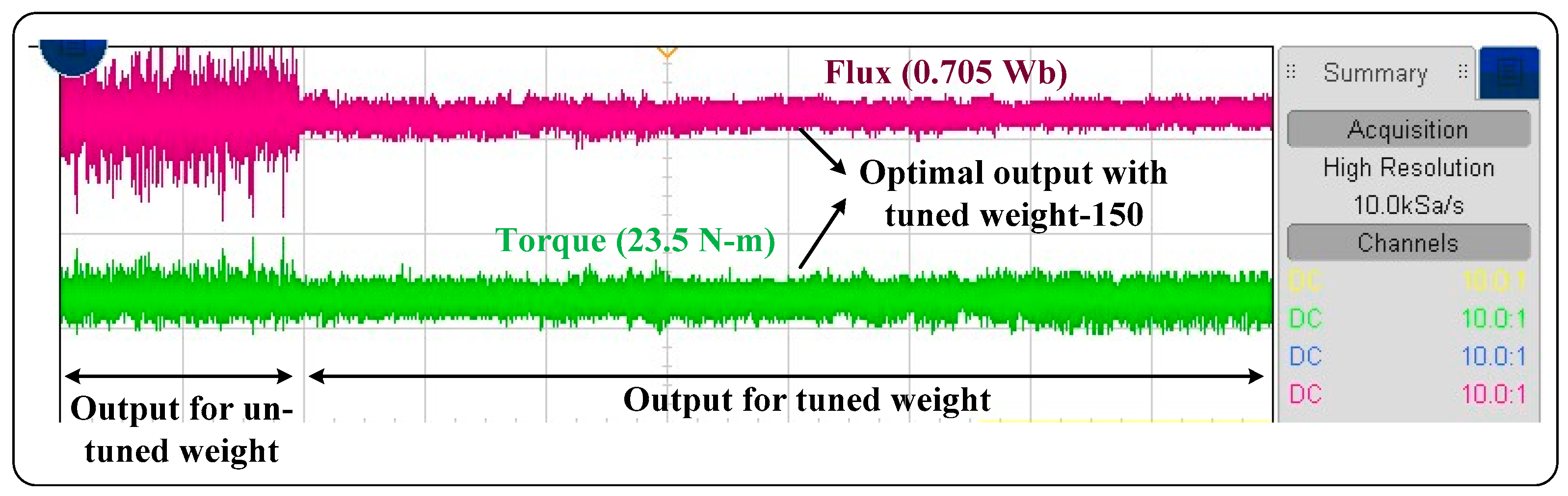
Table 3 lists the OWPMSM drive parameters utilized in the experiment. The experimental hardware is configured with two isolated DC sources whose voltages are set as 300 V (Vdc/2). Furthermore, in all experimentations, control frequency is set to 10 kHz, implying a sampling interval of 100 μs. Entire experimentations are segregated into three tests. In test-1, steady state analysis is performed. In test-2, dynamic analysis with respect to load transients and speed transients is exhibited. Finally, in test-3, the computation times are investigated. To attain an optimal response of the OWPMSM drive, weighting factor tuning in basic PTC is more difficult. However, for a better comparison of the proposed PTC with the basic PTC, preliminary tests on the basic PTC are conducted to determine the optimal weight value, which is 150 as presented in Figure 8. This time-consuming procedure is a problem in basic PTC that the proposed PTC attempts to avoid and gain overall optimal control response without a weighting factor. Also, in the proposed PTC, the PI regulator gains are tuned empirically. Indeed, the fine-tuning of PI controller gains is simpler than the adjustment of weighting factors [35].
Table 3.
OWPMSM drive test-setup.
Figure 8.
Preliminary tests on basic PTC to determine optimal response.
- (i).
- Steady-state analysis (Test-1):
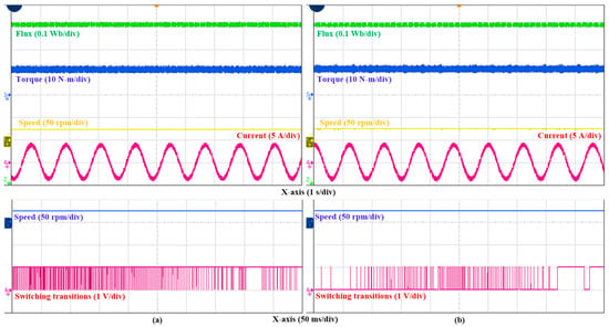
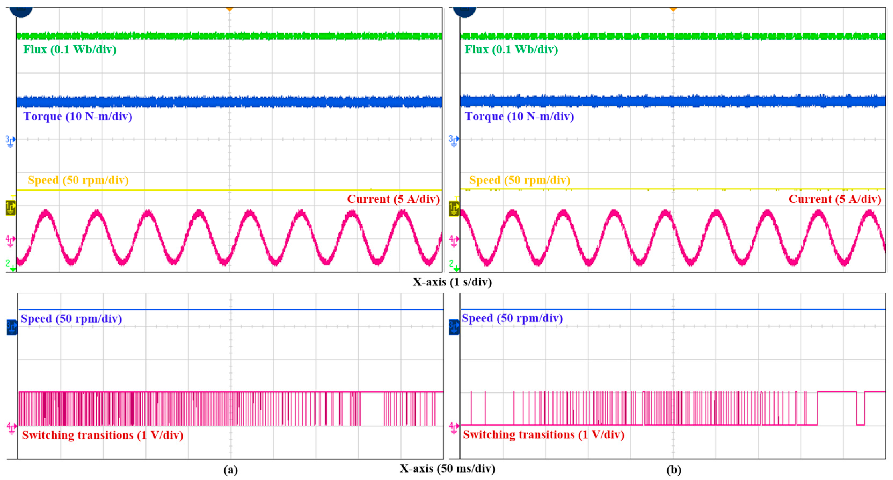
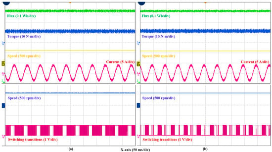
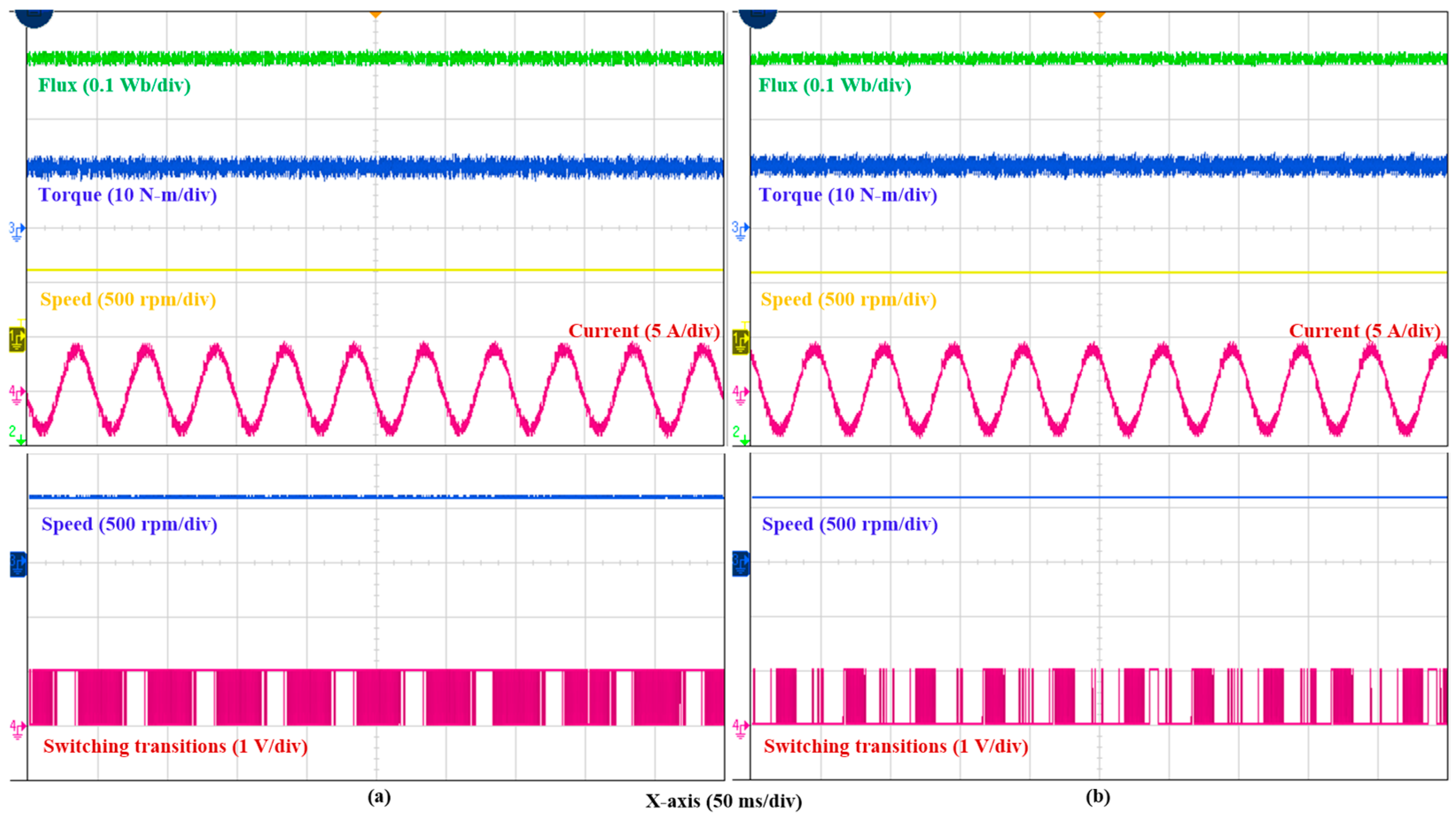
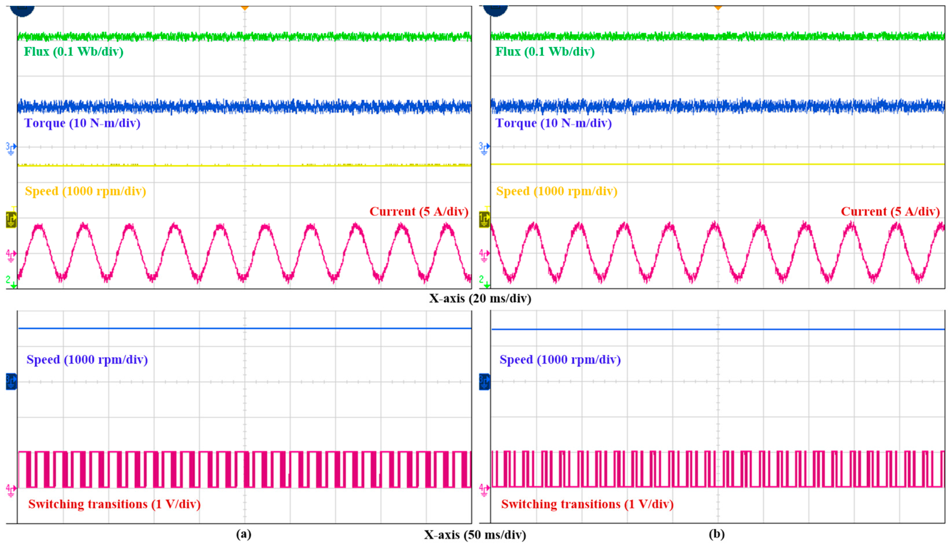
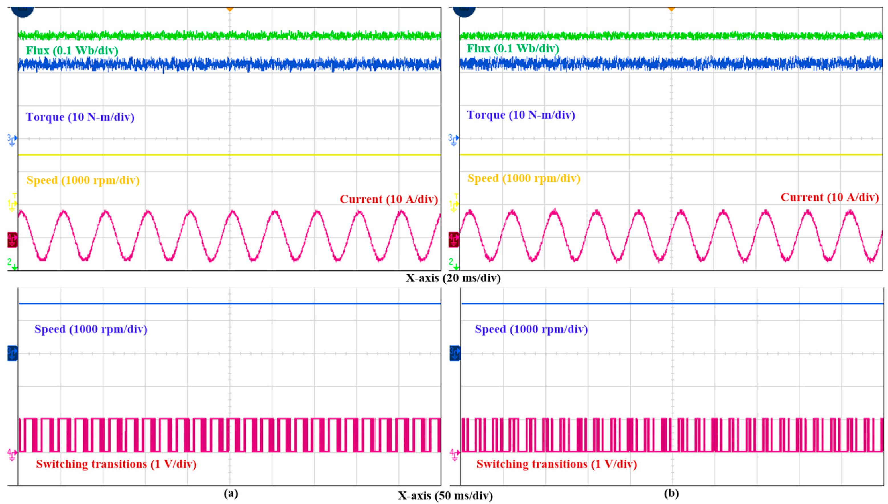
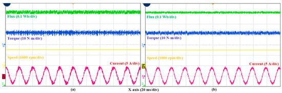
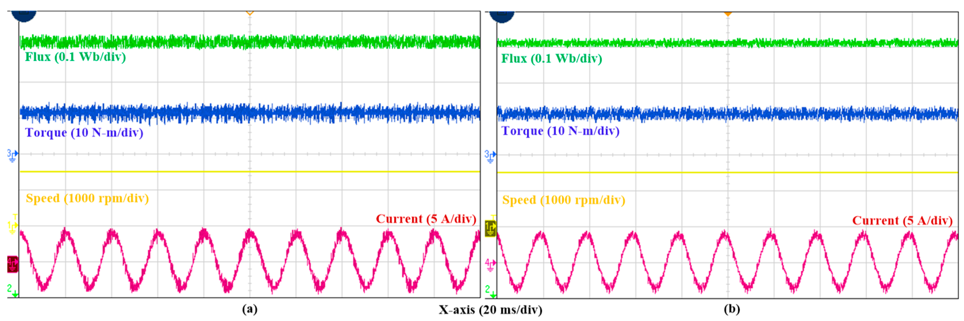
During loading condition of the OWPMSM drive under 12 N-m and reference speeds at 25 rpm, 600 rpm, and 1500 rpm, the steady-state performance of the basic PTC and proposed PTC are displayed in Figure 9, Figure 10 and Figure 11. Figure 12 depicts OWPMSM drive performance obtained for basic and proposed PTC at rated operating conditions (i.e., 1500 rpm and 23.5 N-m).
Figure 9.
Steady-state performance at reference speed 25 rpm and torque 12 N-m: (a) basic PTC and (b) proposed PTC.
Figure 10.
Steady-state performance at reference speed 600 rpm and torque 12 N-m: (a) basic PTC and (b) proposed PTC.
Figure 11.
Steady-state performance at reference speed 1500 rpm and torque 12 N-m: (a) basic PTC and (b) proposed PTC.
Figure 12.
Steady-state performance at reference speed 1500 rpm and torque 23.5 N-m: (a) basic PTC and (b) proposed PTC.
From this analysis, it is clearly evident that optimal OWPMSM drive response is gained in flux, torque, and current for the proposed PTC without a weighting factor and its heuristic tuning, which is problematic in basic PTC. Further, these results prove that the proposed PTC evaluations with limited prediction VVs do not sacrifice steady-state performance. Thus, optimal steady-state performance is retained with effective limited VVs in the proposed PTC. Due to proper utilization of redundant switching states to minimize switching state transitions, switching frequency is also lower in the proposed PTC when compared with the basic PTC. Analyzing the above-presented results, in both the basic and proposed PTC methods, the observed steady-state errors for torque and flux are mathematically negligible, measuring approximately 0.01 Nm and 0.001 Wb, respectively, throughout the steady-state operation. Because reference tracking is highly accurate in both methods, a more in-depth analysis of the steady-state performance is subsequently carried out by evaluating the torque and flux ripples (standard deviation). Thus, by applying standard deviation for the obtained torque and flux response, ripples are calculated. Counting the number of state transitions during a particular time interval and dividing the sum by the interval’s length and number of switches yields the average device switching frequency.
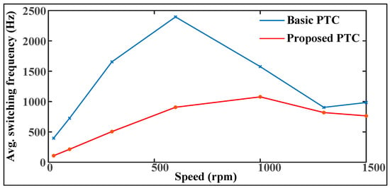
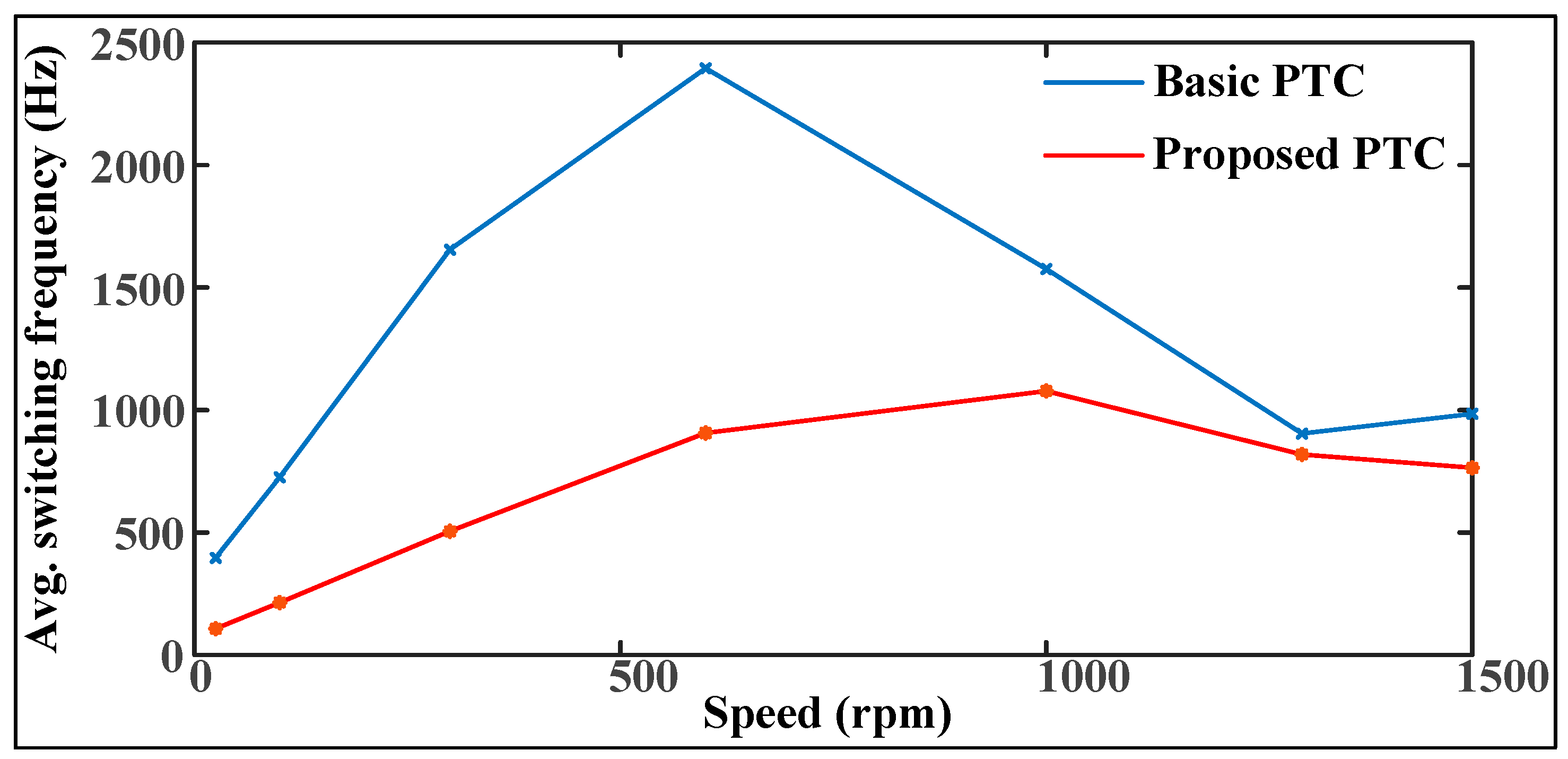
From the above presented results, the obtained performance parameters of torque and flux ripple, current THD, and switching frequency are listed in Table 4. The experimental data of the proposed PTC in comparison with the basic PTC depict that, having a slight variation in torque ripple, flux ripple, and current THD, a reduction is gained in switching frequency. In generality, at 12 N-m load torque, obtained experimental data of switching frequencies for various speed references are plotted in Figure 13. Therefore, without a weighting factor and its heuristic tuning, with limited effective prediction VVs, overall optimal steady-state performance of the OWPMSM drive is achieved when operated with the proposed PTC.
Table 4.
Performance evaluation of basic and proposed PTC.
Figure 13.
Average switching frequency data.
- (ii).
- Dynamic analysis (Test-2):
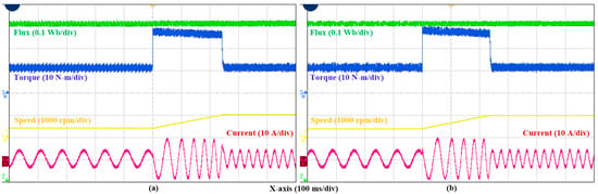
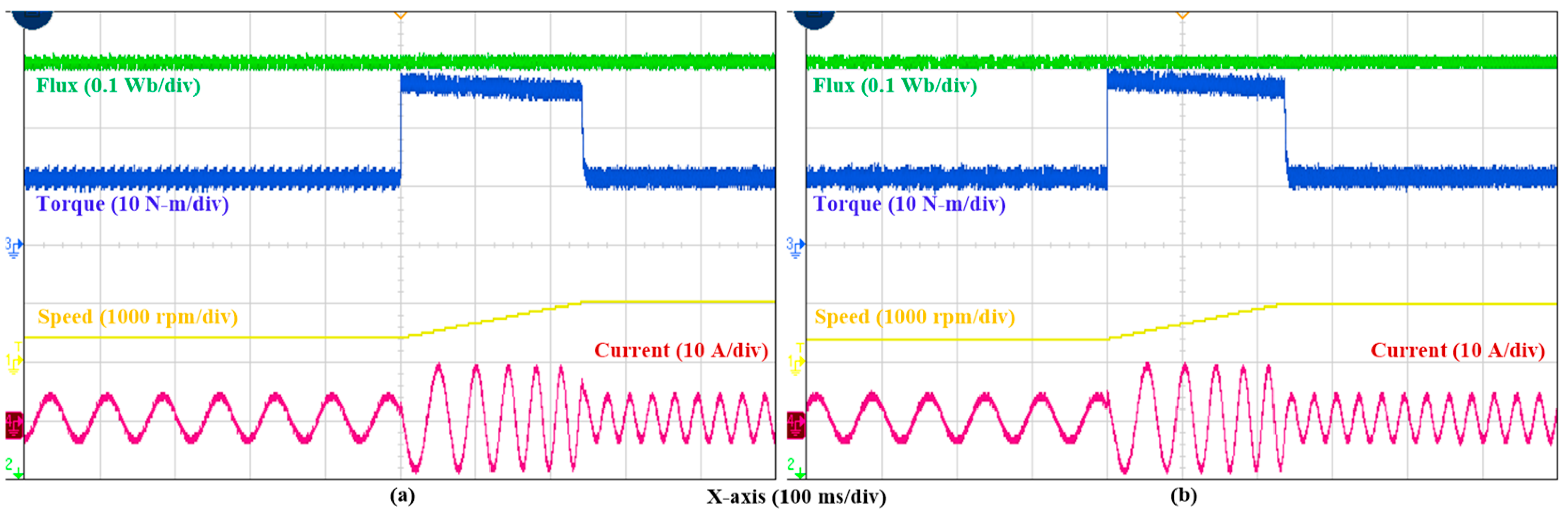
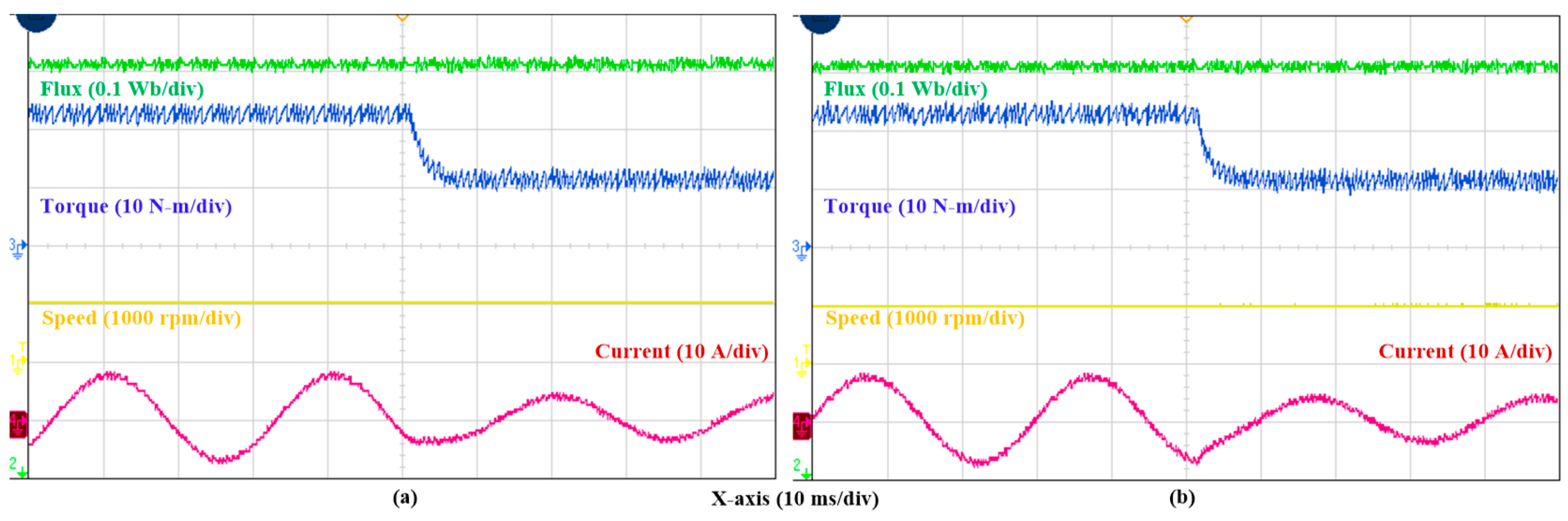
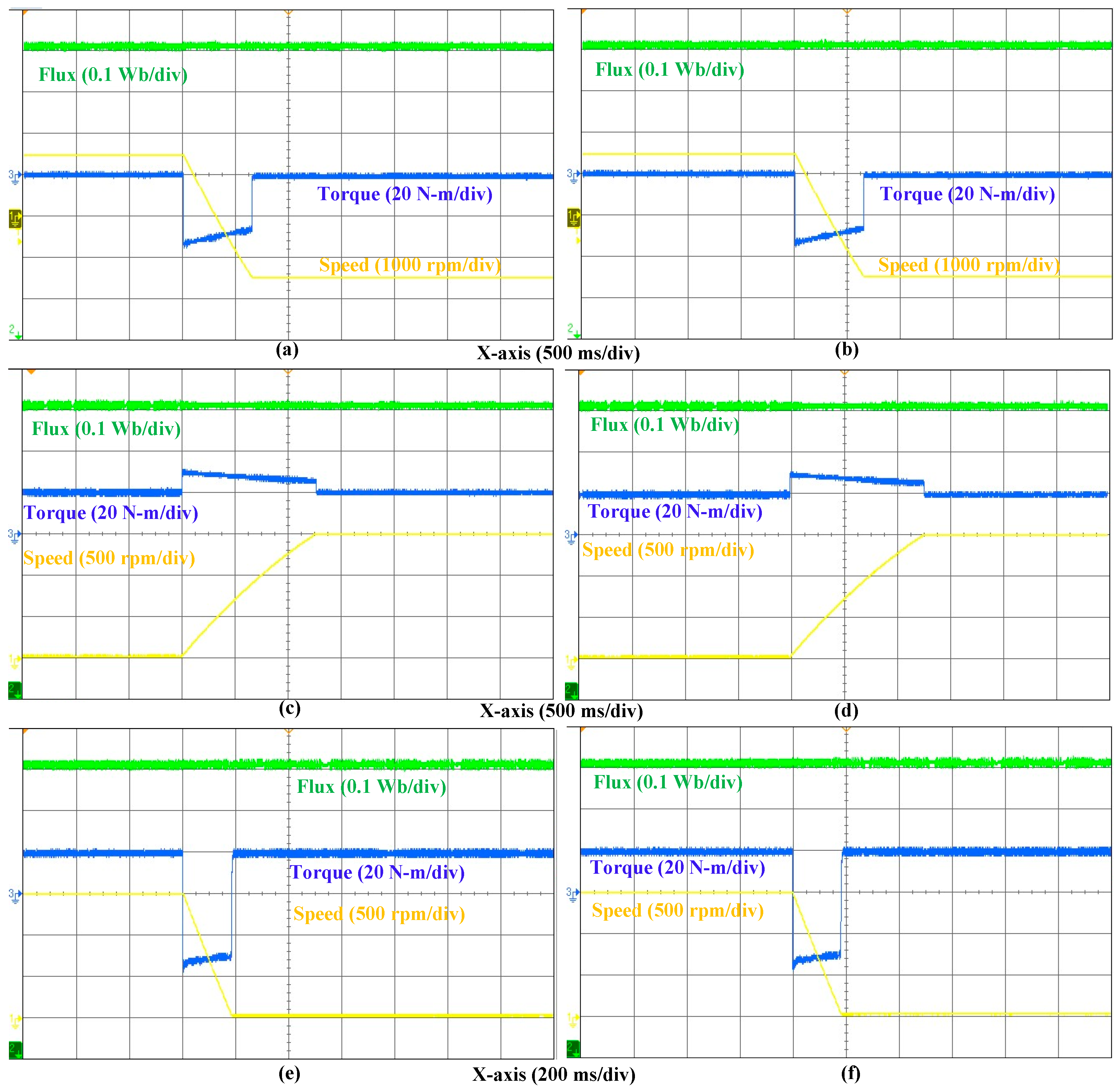
Figure 14 and Figure 15 depict the speed and load torque dynamics during basic and proposed PTC operation. Figure 14 describes the dynamic responses of motor speed, torque, and current when the reference speed is abruptly raised from 400 rpm to 1000 rpm under a constant load torque of 12 N-m. On the other side, under a constant speed of 1000 rpm, when load torque is quickly reduced from 23.5 N-m to 12 N-m, the dynamic results of motor speed, torque, and current are seen in Figure 15. Further, the comprehensive dynamic analysis of basic PTC (in Figure 16a,c,e) and proposed PTC (in Figure 16b,d,f) is as follows: (i) Speed reversal is directing from forward (+1500 rpm) to reverse (−1500 rpm), as indicated in Figure 16a,b. At a high load torque of 20 N-m: (ii) Speed variation from initial low speed (20 rpm) to final high speed (1500 rpm) offers rapid acceleration, as indicated in Figure 16c,d. (iii) Speed variation from initial high speed (1500 rpm) to final low speed (20 rpm) offers rapid deceleration, as indicated in Figure 16e,f. The overall captured results indicate that both techniques provide satisfactory dynamic control. Therefore, the proposed PTC operation has no negative effect on the dynamic response for the OWPMSM drive, and this verifies that reducing the candidate voltage-vector set does not noticeably compromise the dynamic performance. Overall, the proposed limited prediction VVs and control are said to be effective.
Figure 14.
Response of OWPMSM drive during speed dynamics from 400 rpm to 1000 rpm: (a) basic PTC and (b) proposed PTC.
Figure 15.
Response of OWPMSM drive during load dynamics from 23.5 N-m to 12 N·m: (a) basic PTC and (b) proposed PTC.
Figure 16.
Speed dynamic analysis: (a,c,e) basic PTC and (b,d,f) proposed PTC.
- (iii).
- Computation times (Test-3):
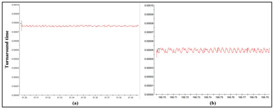
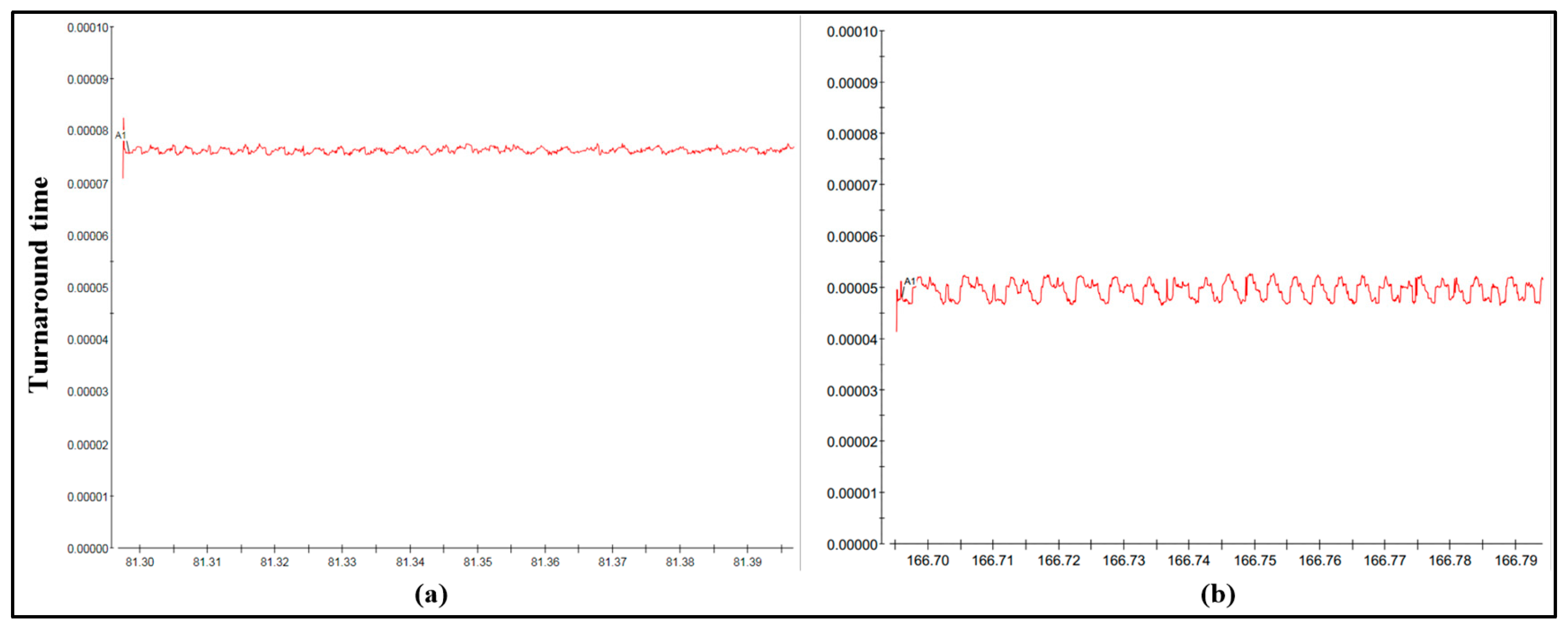
During functioning of the OWPMSM drive, the computation times for both basic and proposed PTC techniques are displayed in Figure 17. Basic PTC has an overall computation time of 76 μs, which is much higher than the proposed PTC, which has only 49 μs. Due to the absence of complex mathematical analysis and having fewer computational steps with limited prediction VVs of 5 over 19, the proposed PTC gains much less computation time when compared to basic PTC. Table 5 is framed where the detailed average execution timings of each stage involved in the basic and proposed PTC methods are listed. This evidence more convincingly demonstrates that the computational reduction originates from the proposed algorithm by the support of simple control operation along with the limited effective prediction VVs.
Figure 17.
Turnaround time from dSPACE Control Desk: (a) basic PTC and (b) proposed PTC.
Table 5.
Computational analysis.
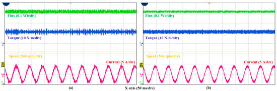
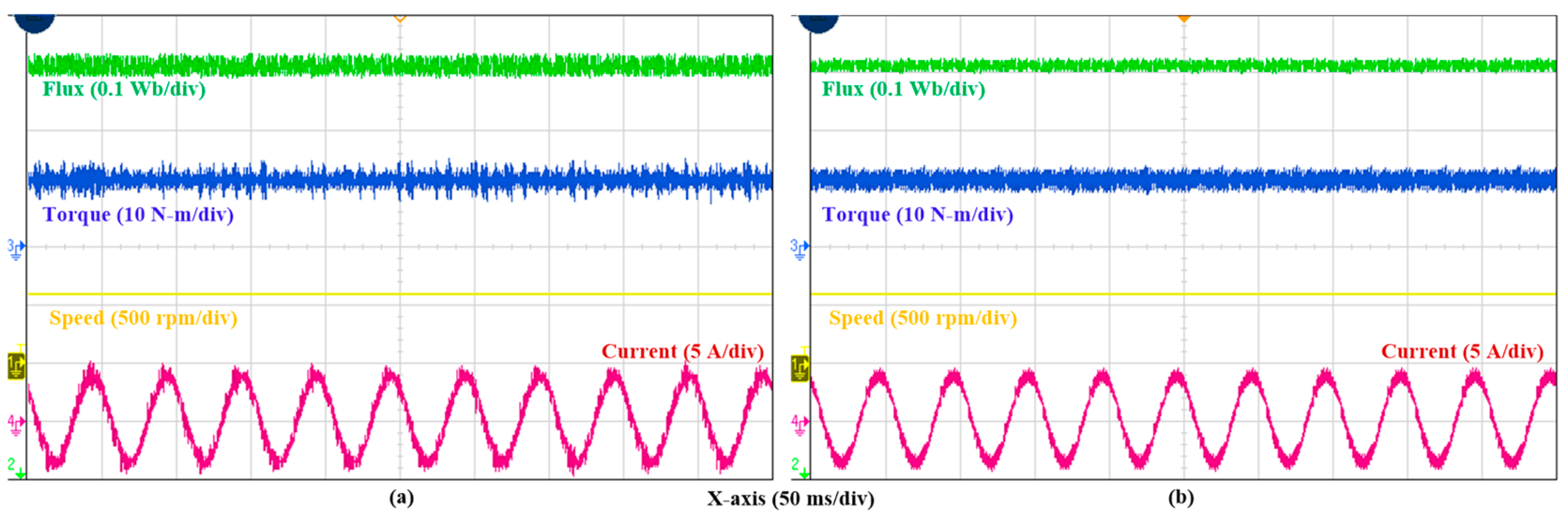
From the above three tests, it is proved that the proposed PTC with low complexity operation has an optimal impact on steady state performance without a weighting factor and its heuristic tuning. Further, novelty and proficiency of the proposed PTC are verified by comparison with the recent weighting-factor-less PTC [11] technique. The PTC [11] concept is implemented for the OWPMSM drive, and its response under mismatch in inductance parameter is presented in Figure 18a and Figure 19a. Whereas the proposed PTC operation is independent of the inductance parameter, the response of the OWPMSM drive is unaffected as displayed in Figure 18b and Figure 19b. The obtained performance parameters of proposed PTC in comparison with PTC [11] are listed in Table 6. Therefore, robustness of the proposed PTC is verified.
Figure 18.
Steady-state performance at reference speed 600 rpm and torque 12 N-m: (a) PTC [11] and (b) proposed PTC.
Figure 19.
Steady-state performance at reference speed 1500 rpm and torque 12 N-m: (a) PTC [11] and (b) proposed PTC.
Table 6.
Performance evaluation of [11] and proposed PTC.
5. Conclusions
This research proposes a simpler, robust weighting-factor-less PTC technique for enhancement of dual inverter fed OWPMSM drive response. Instead of individual torque and flux control objectives in CF, a voltage CF is suggested to serve as a combined torque and flux control. As a result, the weighting factor and its time-consuming tuning process are avoided. In addition, the entire control process is robust since it is independent of inductance and rotor flux parameters, and no strong parameter-dependent mathematical analysis is involved. Using a simple scheme of prediction VV limitation, optimal VV is arrived with only five evaluations instead of having 19 evaluations. This implies a reduction in computational time. By employing feasible redundant switching states of optimal VV, minimization of switching state transitions has been devised, and thereby, switching frequency reduction is gained. Both existing and proposed PTC have been subjected to comparative experimental investigations on OWPMSM drive. With low computation effort, robustness, and no weighting factor tuning, the proposed PTC provides optimal steady state performance than existing PTC, according to the obtained response of torque, flux, current, and switching frequency. Therefore, the entire discussion and results verify the potential of the proposed PTC for OWPMSM drive operation.
Author Contributions
R.E.K.M.: Conceptualization, data curation, formal analysis, investigation, methodology, validation, writing—original draft. R.R.U.: Conceptualization, data curation, formal analysis, investigation, methodology, writing—review and editing. K.R.C.: Formal analysis, project administration, resources, supervision, writing—review and editing. R.M.: Project administration, resources, software, writing—review and editing. S.R.C.: Project administration, resources, software, writing—review and editing. All authors have read and agreed to the published version of the manuscript.
Funding
The authors would like to thank “SRM University-AP, Amaravati, Andhra Pradesh, India-522240” for paying the Article Processing Charges (APCs) for this publication.
Data Availability Statement
The original contributions presented in this study are included in the article. Further inquiries can be directed to the corresponding author.
Acknowledgments
(i) This work was supported by the “Advanced Power Converters Design” Lab and “Power Electronics and Drives” Lab at “Dept. EEE, SRM Institute of Science and Technology, Kattankulathur, India.” (ii) This work was supported by the “Smart mobility Lab” SRM University-AP, Amaravati, Andhra Pradesh, India-522240.
Conflicts of Interest
Author Sreekanth Reddy Chalapala was employed by the company Ford Motor Company. The remaining authors declare that the research was conducted in the absence of any commercial or financial relationships that could be construed as a potential conflict of interest.
References
- Wang, F.; Zhang, Z.; Mei, X.; Rodríguez, J.; Kennel, R. Advanced control strategies of induction machine: Field oriented control, direct torque control and model predictive control. Energies 2018, 11, 120. [Google Scholar] [CrossRef] [Scilit]
- Rodriguez, J.; Kennel, R.M.; Espinoza, J.R.; Trincado, M.; Silva, C.A.; Rojas, C.A. High-Performance Control Strategies for Electrical Drives: An Experimental Assessment. IEEE Trans. Ind. Electron. 2012, 59, 812–820. [Google Scholar] [CrossRef] [Scilit]
- Li, X.; Xue, Z.; Zhang, L.; Hua, W. A Low-Complexity Three-Vector-Based Model Predictive Torque Control for SPMSM. IEEE Trans. Power Electron. 2021, 36, 13002–13012. [Google Scholar] [CrossRef] [Scilit]
- Siami, M.; Khaburi, D.A.; Rodríguez, J. Torque Ripple Reduction of Predictive Torque Control for PMSM Drives with Parameter Mismatch. IEEE Trans. Power Electron. 2017, 32, 7160–7168. [Google Scholar] [CrossRef] [Scilit]
- Sun, X.; Hu, C.; Zhu, J.; Wang, S.; Zhou, W.; Yang, Z.; Lei, G.; Li, K.; Zhu, B.; Guo, Y. MPTC for PMSMs of EVs With Multi-Motor Driven System Considering Optimal Energy Allocation. IEEE Trans. Magn. 2019, 55, 1–6. [Google Scholar] [CrossRef] [Scilit]
- Davari, S.A.; Khaburi, D.A.; Kennel, R. An Improved FCS–MPC Algorithm for an Induction Motor with an Imposed Optimized Weighting Factor. IEEE Trans. Power Electron. 2012, 27, 1540–1551. [Google Scholar] [CrossRef] [Scilit]
- Rojas, C.A.; Rodriguez, J.; Villarroel, F.; Espinoza, J.R.; Silva, C.A.; Trincado, M. Predictive Torque and Flux Control Without Weighting Factors. IEEE Trans. Ind. Electron. 2013, 60, 681–690. [Google Scholar] [CrossRef] [Scilit]
- Bándy, K.; Stumpf, P. Model Predictive Torque Control for Multilevel Inverter fed Induction Machines Using Sorting Networks. IEEE Access 2021, 9, 13800–13813. [Google Scholar] [CrossRef] [Scilit]
- Norambuena, M.; Rodriguez, J.; Zhang, Z.; Wang, F.; Garcia, C.; Kennel, R. A Very Simple Strategy for High-Quality Performance of AC Machines Using Model Predictive Control. IEEE Trans. Power Electron. 2019, 34, 794–800. [Google Scholar] [CrossRef] [Scilit]
- Zhang, Y.; Zhang, B.; Yang, H.; Norambuena, M.; Rodriguez, J. Generalized Sequential Model Predictive Control of IM Drives with Field-Weakening Ability. IEEE Trans. Power Electron. 2019, 34, 8944–8955. [Google Scholar] [CrossRef] [Scilit]
- Davari, S.A.; Norambuena, M.; Nekoukar, V.; Garcia, C.; Rodriguez, J. Even-Handed Sequential Predictive Torque and Flux Control. IEEE Trans. Ind. Electron. 2020, 67, 7334–7342. [Google Scholar] [CrossRef] [Scilit]
- Wang, F.; Xie, H.; Chen, Q.; Davari, S.A.; Rodríguez, J.; Kennel, R. Parallel Predictive Torque Control for Induction Machines Without Weighting Factors. IEEE Trans. Power Electron. 2020, 35, 1779–1788. [Google Scholar] [CrossRef] [Scilit]
- Kusuma, E.; Eswar, K.M.R.; Kumar, T.V. An Effective Predictive Torque Control Scheme for PMSM Drive Without Involvement of Weighting Factors. IEEE J. Emerg. Sel. Top. Power Electron. 2021, 9, 2685–2697. [Google Scholar] [CrossRef] [Scilit]
- Arshad, M.H.; Abido, M.A.; Salem, A.; Elsayed, A.H. Weighting Factors Optimization of Model Predictive Torque Control of Induction Motor Using NSGA-II With TOPSIS Decision Making. IEEE Access 2019, 7, 177595–177606. [Google Scholar] [CrossRef] [Scilit]
- Muddineni, V.P.; Bonala, A.K.; Sandepudi, S.R. Enhanced weighting factor selection for predictive torque control of induction motor drive based on VIKOR method. IET Electr. Power Appl. 2016, 10, 877–888. [Google Scholar] [CrossRef] [Scilit]
- Muddineni, V.P.; Bonala, A.K.; Sandepudi, S.R. Grey Relational Analysis-Based Objective Function Optimization for Predictive Torque Control of Induction Machine. IEEE Trans. Ind. Appl. 2021, 57, 835–844. [Google Scholar] [CrossRef] [Scilit]
- Guazzelli, P.R.U.; de Andrade Pereira, W.C.; de Oliveira, C.M.R.; de Castro, A.G.; de Aguiar, M.L. Weighting Factors Optimization of Predictive Torque Control of Induction Motor by Multiobjective Genetic Algorithm. IEEE Trans. Power Electron. 2019, 34, 6628–6638. [Google Scholar] [CrossRef] [Scilit]
- Rojas, C.A.; Rodriguez, J.R.; Kouro, S.; Villarroel, F. Multiobjective Fuzzy-Decision-Making Predictive Torque Control for an Induction Motor Drive. IEEE Trans. Power Electron. 2017, 32, 6245–6260. [Google Scholar] [CrossRef] [Scilit]
- Novak, M.; Xie, H.; Dragicevic, T.; Wang, F.; Rodriguez, J.; Blaabjerg, F. Optimal Cost Function Parameter Design in Predictive Torque Control (PTC) Using Artificial Neural Networks (ANN). IEEE Trans. Ind. Electron. 2021, 68, 7309–7319. [Google Scholar] [CrossRef] [Scilit]
- Habibullah, M.; Lu, D.D.-C.; Xiao, D.; Fletcher, J.E.; Rahman, M.F. Low complexity predictive torque control strategies for a three-level inverter driven induction motor. IET Electr. Power Appl. 2017, 11, 776–783. [Google Scholar] [CrossRef] [Scilit]
- Zhang, Y.; Yang, H. Two-Vector-Based Model Predictive Torque Control Without Weighting Factors for Induction Motor Drives. IEEE Trans. Power Electron. 2016, 31, 1381–1390. [Google Scholar] [CrossRef] [Scilit]
- Li, X.; Xue, Z.; Yan, X.; Zhang, L.; Ma, W.; Hua, W. Low-Complexity Multivector-Based Model Predictive Torque Control for PMSM With Voltage Preselection. IEEE Trans. Power Electron. 2021, 36, 11726–11738. [Google Scholar] [CrossRef] [Scilit]
- Zhang, X.; Hou, B. Double Vectors Model Predictive Torque Control Without Weighting Factor Based on Voltage Tracking Error. IEEE Trans. Power Electron. 2018, 33, 2368–2380. [Google Scholar] [CrossRef] [Scilit]
- Zhang, Y.; Bai, Y.; Yang, H. A Universal Multiple-Vector-Based Model Predictive Control of Induction Motor Drives. IEEE Trans. Power Electron. 2018, 33, 6957–6969. [Google Scholar] [CrossRef] [Scilit]
- Habibullah, M.; Lu, D.D.; Xiao, D.; Rahman, M.F. Finite-State Predictive Torque Control of Induction Motor Supplied from a Three-Level NPC Voltage Source Inverter. IEEE Trans. Power Electron. 2017, 32, 479–489. [Google Scholar] [CrossRef] [Scilit]
- Wang, Y.; Zhang, Z.; Huang, W.; Kennel, R.; Xie, W.; Wang, F. Encoderless Sequential Predictive Torque Control with SMO of 3L-NPC Converter-fed Induction Motor Drives for Electrical Car Applications. In Proceedings of the 2019 IEEE International Symposium on Predictive Control of Electrical Drives and Power Electronics (PRECEDE), Quanzhou, China, 31 May–2 June 2019; pp. 1–6. [Google Scholar] [CrossRef] [Scilit]
- Muddineni, V.P.; Bonala, A.K.; Yada, H.K. Sequential Selection-Based Predictive Direct Torque Control for Cascaded H-Bridge Inverter-Driven Induction Motor Drive. In Advances in Electrical and Computer Technologies; Springer: Singapore, 2020; pp. 1215–1223. [Google Scholar]
- Yao, H.; Yan, Y.; Cao, Y.; Song, P.; Shi, T. A Variable Duty Cycle-Based Predictive Control for PMSM Fed by Cascaded H-Bridge Inverter. IEEE J. Emerg. Sel. Top. Power Electron. 2022, 10, 4195–4206. [Google Scholar] [CrossRef] [Scilit]
- Le, D.D.; Lee, D.-C. Current Stress Reduction and Voltage Total Harmonic Distortion Improvement of Flying-Capacitor Modular Multilevel Converters for AC Machine Drive Applications. IEEE Trans. Ind. Electron. 2022, 69, 90–100. [Google Scholar] [CrossRef] [Scilit]
- Zhou, Z.; Xia, C.; Yan, Y.; Wang, Z.; Shi, T. Torque Ripple Minimization of Predictive Torque Control for PMSM With Extended Control Set. IEEE Trans. Ind. Electron. 2017, 64, 6930–6939. [Google Scholar] [CrossRef] [Scilit]
- Gong, C.; Hu, Y.; Li, W.; Gao, J.; Liu, J.; Wen, H.; Yang, J. Hybrid DC-Bus Capacitor Discharge Strategy Using Internal Windings and External Bleeder for Surface-Mounted PMSM-Based EV Powertrains in Emergency. IEEE Trans. Ind. Electron. 2021, 68, 1905–1915. [Google Scholar] [CrossRef] [Scilit]
- Lakhimsetty, S.; Somasekhar, V.T. A Four-Level Open-End Winding Induction Motor Drive with a Nested Rectifier–Inverter Combination with Two DC Power Supplies. IEEE Trans. Power Electron. 2019, 34, 8894–8904. [Google Scholar] [CrossRef] [Scilit]
- Muduli, U.R.; Beig, A.R.; Behera, R.K.; Jaafari, K.A.; Alsawalhi, J.Y. Predictive Control with Battery Power Sharing Scheme for Dual Open-End-Winding Induction Motor Based Four-Wheel Drive Electric Vehicle. IEEE Trans. Ind. Electron. 2022, 69, 5557–5568. [Google Scholar] [CrossRef] [Scilit]
- Kusuma, E.; Thippiripati, V.K. Effective predictive torque control scheme for four-level open-end winding permanent magnet synchronous motor drive. Int. Trans. Electr. Energy Syst. 2020, 30, e12536. [Google Scholar] [CrossRef] [Scilit]
- Rodriguez, J.; Kazmierkowski, M.P.; Espinoza, J.R.; Zanchetta, P.; Abu-Rub, H.; Young, H.A.; Rojas, C.A. State of the art of finite control set model predictive control in power electronics. IEEE Trans. Ind. Inform. 2012, 9, 1003–1016. [Google Scholar] [CrossRef] [Scilit]
- Zhou, R.; Wang, H. Model Predictive Speed and Voltage Control of Sensorless PMSM With Parameter Rectification and A Reduced-Order EKF. In Proceedings of the IEEE Transactions on Industrial Electronics, Doha, Qatar, 18–21 October 2026. [Google Scholar] [CrossRef] [Scilit]
- Yang, C.; Liu, W.; Song, B.; Chau, K.T. Signal-Injection-Free Online Identification of Temperature-Dependent Electrical Parameters for SPMSM Drives: An Alternating Dual-Adaline Approach. IEEE Trans. Transp. Electrif. 2026. [Google Scholar] [CrossRef] [Scilit]

Disclaimer/Publisher’s Note: The statements, opinions and data contained in all publications are solely those of the individual author(s) and contributor(s) and not of MDPI and/or the editor(s). MDPI and/or the editor(s) disclaim responsibility for any injury to people or property resulting from any ideas, methods, instructions or products referred to in the content. |
© 2026 by the authors. Licensee MDPI, Basel, Switzerland. This article is an open access article distributed under the terms and conditions of the Creative Commons Attribution (CC BY) license.