


Abstract
Abandoned wells pose a significant leakage risk for geological carbon (CO2) storage because defects at the casing–cement interface can create preferential pathways for upward CO2 migration. Although thermo-hydro-mechanical (THM) studies have extensively investigated wellbore integrity, leakage pathways are commonly represented using equivalent cement permeability or prescribed leakage fluxes, limiting the ability to distinguish hydraulic leakage behavior from mechanical response. This study develops a coupled THM model that explicitly represents a pre-existing casing–cement micro-annulus as an independent hydraulic domain within a two-dimensional axisymmetric wellbore system. Sensitivity analyses were performed to evaluate the effects of injection pressure, micro-annulus aperture, and cement stiffness on leakage behavior and stress redistribution. Increasing the aperture from 0.5 to 1.0 mm increased effective permeability from 2.08 × 10⁻⁸ to 8.33 × 10⁻⁸ m2 and increased the average micro-annulus velocity from 2.85 to 11.42 m/s. In contrast, increasing injection pressure from 15 to 25 MPa increased the maximum von Mises stress from 33.52 to 47.58 MPa, with negligible influence on leakage velocity. Increasing the cement’s Young’s modulus from 10 to 30 GPa reduced the maximum von Mises stress from 39.73 to 28.14 MPa without affecting hydraulic conductance. The combined pressure–aperture analysis further showed that the highest leakage capacity did not correspond to the highest stress concentration. These results demonstrate that micro-annulus geometry primarily controls leakage conductance, whereas injection pressure and cement stiffness primarily control the mechanical response. Within the fixed-aperture thermo-hydro-mechanical (THM) framework adopted in this study, this mechanistic separation provides a physically transparent basis for evaluating CO2 leakage through pre-existing casing–cement micro-annuli in abandoned wells. The proposed framework also provides a foundation for future model developments incorporating stress-dependent aperture evolution, multiphase flow, and coupled geochemical processes.
1. Introduction
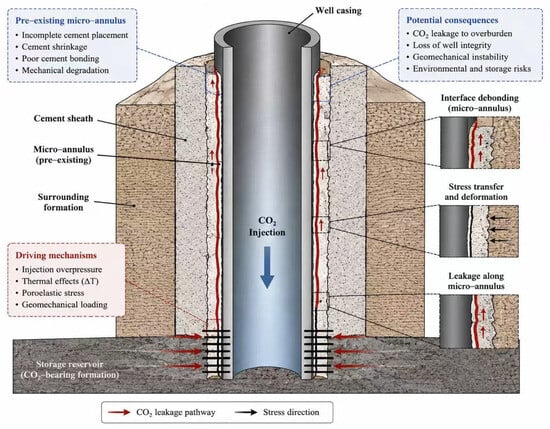
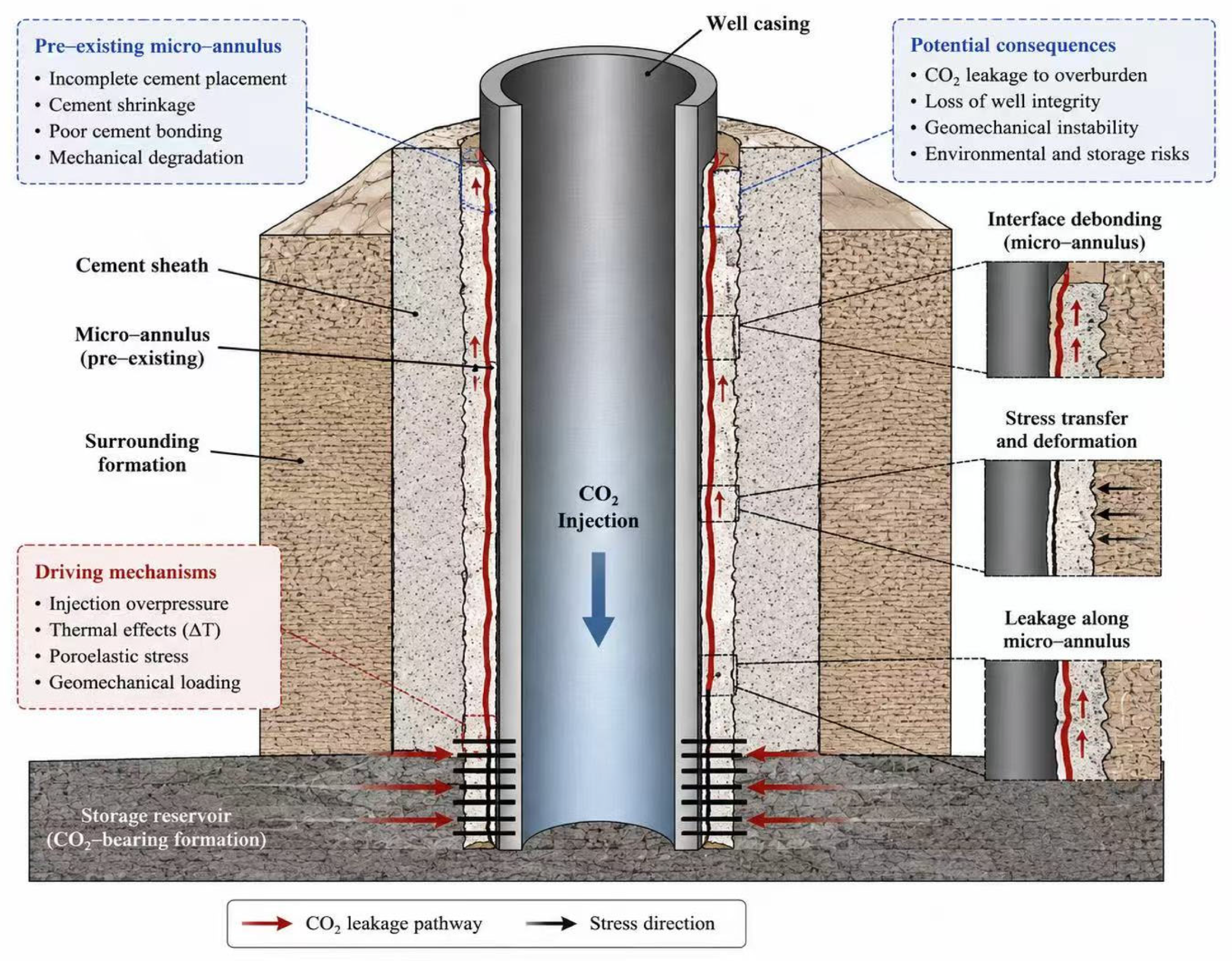
Geological CO2 storage requires long-term hydraulic isolation between the storage reservoir and overlying formations [1,2,3]. Recent site-specific reservoir simulations have demonstrated the technical feasibility of CO2 storage in real geological formations and have highlighted the importance of evaluating injection performance, storage capacity, pressure evolution, and long-term containment under realistic geological conditions [4]. Abandoned wells are among the most critical engineered leakage risks because they directly penetrate storage intervals, caprocks, and shallow formations [5,6,7]. Unlike intact geological seals, abandoned wells contain multiple man-made interfaces, including casing–cement contacts, cement formation contacts, plugs, and degraded cement sections [8]. These interfaces may lose hydraulic integrity through pressure cycling, thermal mismatch, cement shrinkage, imperfect bonding, and long-term material degradation, creating potential leakage pathways for stored CO2 [9,10]. Among these pathways, the casing–cement interface is particularly important because micro-annular defects can provide continuous or semi-continuous conduits for CO2 migration even when the cement matrix itself remains relatively impermeable [11]. Figure 1 presents a conceptual illustration of CO2 leakage through a pre-existing casing–cement micro-annulus and the associated thermo-hydro-mechanical (THM) interactions considered in this study.
Figure 1.
Conceptual model of CO2 leakage through a pre-existing casing–cement micro-annulus.
In such systems, leakage behavior is governed not only by the intrinsic permeability of the cement sheath but also by the aperture and hydraulic conductance of the interfacial defect [12]. Consequently, abandoned well leakage assessment requires a modeling framework capable of distinguishing matrix-controlled flow from interface-controlled leakage. Previous investigations of wellbore integrity in geological CO2 storage have focused on the coupled effects of pressure loading, thermal perturbation, cement degradation, and interface debonding on long-term containment performance [9,13,14]. Recent THM studies have improved the understanding of stress redistribution around casing–cement and cement formation interfaces, demonstrating that variations in reservoir pressure and temperature can significantly influence wellbore stability and leakage risk [12,15]. In parallel, laboratory investigations have shown that micro-annular defects at the casing–cement interface can act as highly conductive preferential pathways for gas migration, even when the surrounding cement matrix exhibits very low permeability [16,17]. These findings collectively highlight the importance of interfacial defects as critical controls on wellbore leakage behavior. To represent these processes numerically, many leakage assessments employ equivalent permeability formulations, leakage source terms, or simplified boundary conditions to describe degraded wellbore systems. Although such approaches are computationally efficient and suitable for large-scale risk screening, they generally do not resolve the micro-annulus explicitly as a separate hydraulic domain. Consequently, the influence of micro-annulus geometry is commonly embedded within bulk cement properties or leakage assumptions, making it difficult to distinguish the individual contributions of hydraulic conductance and stress redistribution to overall wellbore performance [18]. Furthermore, although hydraulic leakage and mechanical integrity are frequently evaluated within the same modeling framework, the extent to which they are controlled by different physical parameters remains insufficiently understood. Experimental studies have demonstrated the dominant influence of micro-annulus geometry on gas transmissivity, while numerical THM investigations have highlighted the importance of stress redistribution around wellbore interfaces [17,19]. However, the interaction between aperture-controlled leakage conductance and mechanical integrity response remains insufficiently quantified. A wider micro-annulus may substantially increase leakage conductance, whereas a narrower defect subjected to elevated injection pressure may generate greater local stress concentration [20]. Consequently, the condition associated with the highest leakage potential may not correspond to the mechanically most critical condition. This limitation hinders the mechanistic interpretation of leakage risk and complicates the identification of the dominant factors governing abandoned well performance during long-term CO2 storage. To address these limitations, this study develops a coupled THM model for CO2 leakage through a pre-existing micro-annulus at the casing–cement interface of an abandoned wellbore. The micro-annulus is explicitly represented as an independent hydraulic domain within a two-dimensional axisymmetric numerical model consisting of casing, micro-annulus, cement sheath, and surrounding formation. Leakage conductance is controlled directly by the prescribed aperture of the interfacial defect, while stress redistribution is evaluated through the coupled THM response. Unlike conventional leakage formulations that embed interface effects within equivalent permeability assumptions, the present framework explicitly represents the micro-annulus as an aperture-controlled leakage domain and enables hydraulic leakage capacity and mechanical integrity response to be evaluated separately within the same THM model. Sensitivity analyses of injection pressure, micro-annulus aperture, combined pressure–aperture conditions, and cement stiffness are performed to identify the dominant controls on leakage behavior and stress redistribution, thereby providing a mechanistic basis for interpreting abandoned well leakage risk in geological CO2 storage systems.
2. Methodology
2.1. Model Description and Assumptions
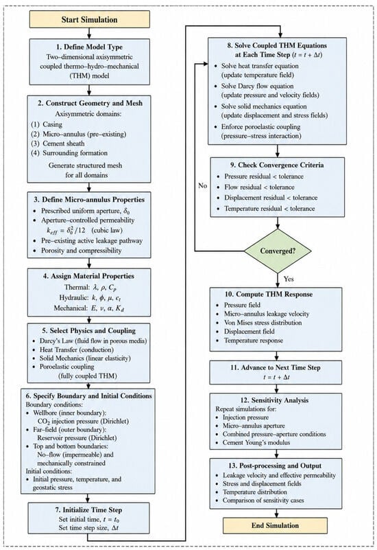
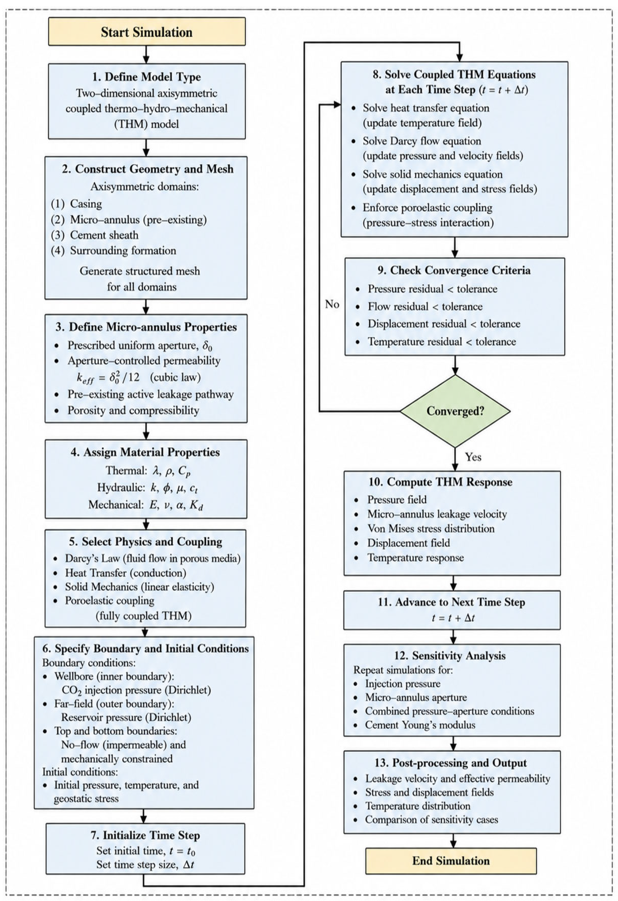
A coupled thermo-hydro-mechanical (THM) model was developed to evaluate CO2 leakage through a pre-existing micro-annulus at the casing–cement interface of an abandoned wellbore. The model focuses on the near-wellbore region above the injection interval, where CO2 pressurization and thermal disturbance generate the strongest local gradients in pore pressure, temperature, and stress [21]. This region is critical because leakage initiation or acceleration in abandoned wells is commonly controlled by the integrity of the casing–cement interface rather than by the far-field reservoir response [22]. The wellbore system was represented using a two-dimensional axisymmetric finite element method (FEM), as shown in Figure 2. The axisymmetric representation assumes concentric casing, micro-annulus, cement sheath, and formation domains, with the prescribed micro-annulus extending continuously and uniformly around the casing circumference. Consequently, the model does not resolve azimuthally variable aperture, discontinuous leakage channels, casing eccentricity, non-uniform cement-sheath thickness, or localized casing–cement contact patches.
Figure 2.
Numerical workflow of the coupled thermo-hydro-mechanical (THM) model.
The computational domain consists of four concentric regions: the steel casing, micro-annulus, cement sheath, and surrounding formation. Unlike simplified leakage models that prescribe leakage through an equivalent boundary or assign a bulk permeability to the cement sheath, the present model explicitly represents the micro-annulus as a separate hydraulic domain at the casing–cement interface. This formulation allows pressure propagation, heat transfer, and stress redistribution to be solved simultaneously around the leakage pathway, thereby linking interfacial hydraulic conductance with the mechanical response of the wellbore system [23,24]. In the present implementation, the micro-annulus is treated as a pre-existing hydraulically active defect. This assumption represents abandoned, aged, or poorly bonded wells in which interfacial debonding exists before CO2 injection or storage-related repressurization [19]. The model therefore does not simulate the initial creation of the micro-annulus. Instead, it quantifies how an existing leakage pathway responds to coupled THM loading and how its prescribed aperture controls effective permeability and leakage velocity. This distinction avoids treating interfacial failure as a purely mechanical damage problem and instead frames the micro-annulus as a leakage-active pathway whose hydraulic behavior is governed by aperture-controlled permeability. The casing, cement, and formation are modeled as linear elastic and isotropic materials. Mechanical deformation is solved under quasi-static conditions because inertial effects are negligible over the pressure diffusion and heat transfer time scales considered. The casing is treated as an impermeable solid, whereas the cement sheath and surrounding formation are represented as porous media. CO2 migration is modeled as single-phase compressible Darcy flow through the prescribed micro-annulus and surrounding porous domains. This assumption represents a pre-existing leakage pathway that is already hydraulically accessible to CO2, rather than the initial displacement of water from a fully saturated casing–cement interface. Accordingly, CO2–water relative permeability, capillary pressure, residual water saturation, capillary trapping, and phase interference are not considered. The calculated leakage response therefore represents the hydraulic capacity of a CO2-accessible pathway and should be interpreted as an upper-bound single-phase estimate rather than a complete prediction of multiphase field leakage. These simplifications isolate the first-order THM controls governing CO2 transport through a prescribed interfacial leakage pathway while avoiding additional uncertainty associated with multiphase flow, capillary interactions, and geochemical alteration. Heat transfer is included to represent the temperature contrast between injected CO2 and the surrounding wellbore system. Temperature changes influence the stress field through thermoelastic deformation, while pore pressure changes modify the effective stress through poroelastic coupling. The model therefore captures the coupled interaction among CO2 pressure propagation, thermal redistribution, and mechanical stress development around an abandoned wellbore containing a pre-existing micro-annulus.
2.2. Governing Equations and Thm Coupling
The coupled THM formulation consists of three interacting fields: mechanical deformation, CO2 flow, and heat transfer. These fields are linked through effective stress coupling, thermoelastic deformation, and advective heat transport associated with CO2 migration. The coupled THM formulation was implemented using the FEM, incorporating solid mechanics, Darcy flow, heat transfer in porous media, and poroelastic coupling. Mechanical equilibrium is described under quasi-static conditions as:
where σ is the total stress tensor (Pa) and b is the body force vector (N/m3). In the present near-wellbore model, inertial terms are neglected because deformation evolves over pressure diffusion and heat transfer time scales rather than dynamic mechanical time scales. The solid domains are assumed to be linear elastic and isotropic. The mechanical boundary conditions were specified to prevent rigid-body motion while preserving realistic deformation of the wellbore system. The lower boundary was constrained in the vertical direction, whereas the outer radial boundary was constrained in the radial direction. The axis of symmetry was assigned along the wellbore centerline. These constraints eliminate rigid-body motion while allowing deformation parallel to the constrained boundaries, thereby representing the confinement imposed by the surrounding geological formation. The strain tensor is defined as
where ε is the strain tensor, and u is the displacement vector (m). For an isotropic elastic material, the mechanical stress contribution is expressed as:
where σm is the elastic stress tensor (Pa), G is the shear modulus (Pa), λ is Lamé’s first parameter (Pa), tr(ε) is the volumetric strain, and I is the identity tensor. The elastic constants are related to Young’s modulus E (Pa) and Poisson’s ratio v by:
Thermal deformation is included through the thermoelastic strain contribution:
where εT is the thermal strain tensor, αT is the linear thermal expansion coefficient (1/k), T is the local temperature (K), and T0 is the reference temperature (K). This term accounts for stress redistribution caused by the temperature contrast between injected CO2 and the surrounding wellbore materials. In the constrained casing–cement formation system, thermal expansion or contraction modifies the local stress state near the casing–cement interface. Pore pressure modifies the stress acting on the porous skeleton through the effective stress relation [25]:
where σ′ is the effective stress tensor (Pa), αB is Biot’s coefficient, and p is pore pressure (Pa). This relation couples CO2 pressurization to the mechanical response of the cement and formation. Increasing pore pressure reduces effective confinement, while thermal loading modifies the total stress field. Their combined effect determines the stress redistribution around the pre-existing micro-annulus [13,26]. CO2 flow is modeled using Darcy’s law:
where q is the Darcy velocity vector (m/s), keff is the effective permeability (m2), µ is CO2 dynamic viscosity (pa.s), and is the pressure gradient (pa/m). Darcy flow is solved in the porous cement, formation, and micro-annulus domain. In the micro-annulus, keff is controlled by the prescribed hydraulic aperture. This provides the hydraulic link between leakage pathway geometry and CO2 velocity. Darcy’s law is chosen because the leakage pathway and surrounding porous domains are treated as continuum porous media. Since the present model is focused on pressure-driven migration through a thin but continuous interfacial defect, Darcy flow provides the appropriate first-order hydraulic description. Darcy’s law governs CO2 transport through the equivalent porous domains, whereas an equation of state, such as the Peng–Robinson equation, describes pressure- and temperature-dependent thermodynamic properties, particularly density and compressibility. Therefore, the Peng–Robinson equation would complement, rather than replace, the Darcy flow formulation. In the present study, CO2 density is represented using the pressure-dependent relation described below. The continuity equation is written as
where ϕ is porosity, ρ is CO2 density (kg/m3), and Qm is the mass source term (kg/m3/s).
This equation is chosen because it ensures transient conservation of mass during injection and leakage. It is required to capture pressure buildup near the wellbore and the subsequent migration of CO2 along the activated interface. For moderate pressure variation in a near-wellbore engineering model, CO2 density is approximated as
where: ρ0 is reference CO2 density (kg/m3), cf is CO2 compressibility (1/Pa), p0 is reference pressure (Pa). In the present model, CO2 density is represented using the linear pressure-dependent compressibility relation in Equation (10). A full cubic equation of state, such as the Peng–Robinson equation, was not explicitly implemented. Although such an equation of state could improve the representation of real-gas density and compressibility, particularly under conditions where these properties vary nonlinearly, it would be coupled with rather than substituted for Darcy’s law. The resulting uncertainty should therefore be considered when interpreting the absolute leakage rate and velocity predictions. The present formulation therefore assumes a hydraulically accessible single-phase CO2 leakage pathway. The implications of this assumption are discussed in Section 3.5. Heat transfer is governed by:
where (ρCp)eff is the effective volumetric heat capacity (J/m3/K), Cp is CO2 specific heat capacity (J/kg/K), kT is thermal conductivity (W/m/K), and QT is the thermal source term (W/m3).
The effective volumetric heat capacity is calculated as
where: ρs (kg/m3) and Cs (J/kg/K) are the density and heat capacity of the solid matrix, respectively. This formulation accounts for conductive heat transfer through the casing, cement, and formation, as well as advective heat transport by CO2 flow in the porous and leakage domains. The THM coupling sequence is defined as follows. Injection pressure drives CO2 migration and pore pressure redistribution; pore pressure variation modifies effective stress through poroelastic coupling; temperature redistribution generates thermoelastic strain and stress; and the resulting stress field is evaluated together with pressure and leakage velocity. In the present implementation, mechanical deformation does not dynamically update the micro-annulus aperture.
2.3. Micro-Annulus Aperture and Permeability Formulation
The casing–cement interface was represented as an explicit micro-annulus domain to describe CO2 leakage through a pre-existing interfacial defect. Unlike approaches that impose leakage as a boundary flux or represent the cement sheath using an equivalent bulk permeability, the present model resolves the micro-annulus as an independent hydraulic pathway [13,16,17,27]. This enables the leakage capacity to be directly linked to the assigned aperture of the interfacial defect. In the present implementation, the micro-annulus is hydraulically active from the beginning of the simulation. No stress-triggered activation switch is applied. The hydraulic aperture is prescribed as:
where b is the hydraulic aperture, and δ0 is the prescribed initial micro-annulus thickness. For each simulation case, b remains constant during the transient calculation. The model therefore does not update aperture from mechanical displacement. Instead, different values of δ0 represent different pre-existing leakage pathway openings. The effective permeability of the micro-annulus is calculated using the permeability form of the parallel plate cubic law approximation:
where keff is the aperture-controlled permeability of the micro-annulus. This relation provides a direct geometric link between interfacial aperture and hydraulic conductance. Since permeability scales with the square of aperture, small changes in micro-annulus thickness can produce large changes in leakage velocity along the casing–cement interface. Equation (14) is based on the classical cubic law approximation for a smooth, uniform micro-annulus. In practice, surface roughness, localized contact, tortuosity, and aperture variability may reduce the effective permeability. These effects were not explicitly considered in the present model and represent an area for future improvement. The prescribed micro-annulus apertures of 0.5 and 1.0 mm were selected based on aperture ranges reported or adopted in previous studies of casing–cement interfacial leakage [28,29,30]. These values were used to represent two literature-based pre-existing leakage pathway conditions and to quantify the sensitivity of hydraulic conductance and coupled THM response to aperture enlargement. They should therefore be interpreted as prescribed degraded interface scenarios rather than as a universal range applicable to all abandoned wells. For the base case, the prescribed micro-annulus thickness is: δ0 = 5.0 × 10⁻⁴ m, which gives:
For the wider micro-annulus case: δ0 = 1.0 × 10⁻³ m, and therefore:
Thus, increasing the aperture from 0.5 mm to 1.0 mm increases keff by a factor of four. This aperture-controlled permeability is the main hydraulic mechanism in the present model and provides the basis for evaluating leakage sensitivity to micro-annulus thickness. The permeability calculated from the prescribed aperture was assigned directly to the micro-annulus domain and remained constant within each simulation case. No damage variable, stress-triggered activation criterion, interface-contact law, or displacement-dependent aperture update was applied. The micro-annulus therefore represents a pre-existing passive gap whose hydraulic conductance is prescribed by its fixed aperture rather than an evolving defect generated by the coupled THM response. This formulation enables the hydraulic influence of the prescribed micro-annulus aperture to be evaluated separately from the pressure-, temperature-, and material-dependent stress response of the wellbore system. Defect initiation, interface debonding, aperture opening or closure, and stress-dependent permeability evolution are outside the scope of the present model.
2.4. Model Parameters, Boundary Conditions, and Numerical Implementation
The numerical model was constructed as a two-dimensional axisymmetric wellbore system consisting of four domains: steel casing, micro-annulus, cement sheath, and surrounding formation. All numerical calculations were performed in SI units. For readability, permeability and Young’s modulus are reported in millidarcies (mD; 1 mD = 9.869 × 10⁻¹⁶ m−2) and gigapascals (GPa; 1 GPa = 109 Pa), respectively. Pressure and stress are reported in MPa, Young’s modulus in GPa, and micro-annulus thickness in mm in the parameter tables and results. The base case geometry is summarized in Table 1. The outer formation radius was set to 2.0 m, providing 1.84 m of surrounding rock beyond the outer cement radius of 0.16 m. This radial extent was selected to represent the near-wellbore THM response while maintaining computational efficiency. The casing, cement sheath, and formation were represented as concentric axisymmetric domains, while the micro-annulus was inserted as a thin hydraulic domain at the casing–cement interface.
Table 1.
Geometrical parameters used in the base case model [28,29,30].
The thermo-mechanical properties assigned to the casing, cement, and formation are listed in Table 2. The casing was treated as an impermeable elastic solid. The cement sheath and formation were represented as porous elastic media to enable coupling between pore pressure and deformation. The micro-annulus was assigned a porosity of 1 and an aperture-controlled permeability calculated from Equation (14).
Table 2.
Base case thermo-mechanical material properties [28,29,30].
The baseline Young’s modulus of the cement sheath was set to 18 GPa, representing a typical value for well-cured oil well cement reported in the literature [28,29,30]. Because the elastic properties of cement vary with formulation, curing conditions, degradation, and long-term service exposure, a wider range of 10–30 GPa was considered in the sensitivity analysis to represent relatively compliant and comparatively stiff cement systems encountered in abandoned wells. The CO2 and micro-annulus parameters used in the base case are given in Table 3. The base micro-annulus aperture was prescribed as 5.0 × 10⁻⁴ m. This aperture was varied in the sensitivity analysis to evaluate leakage pathway control on CO2 velocity.
Table 3.
Fluid and micro-annulus parameters [28,29,30].
At the initial condition, the model was assigned uniform reservoir pressure and temperature:
where p0 is the reference reservoir pressure and Tres is the reservoir temperature. At the inner wellbore boundary, CO2 injection was represented by prescribed pressure and temperature conditions:
At the outer radial boundary, pressure and temperature were maintained at reservoir conditions:
Mechanical boundary conditions were assigned to reproduce axisymmetric near-wellbore deformation. The outer formation boundary provided the mechanical confinement for evaluating stress redistribution induced by CO2 pressurization and thermal contrast. The coupled THM model was solved using the FEM, incorporating solid mechanics, Darcy’s law, heat transfer in porous media, and poroelastic coupling. Solid mechanics was applied to the casing, cement, and formation domains. Darcy’s Law was applied to the cement, formation, and micro-annulus domains. Heat transfer in porous media was used to calculate temperature redistribution in the coupled wellbore system. Poroelasticity coupling linked pore pressure variation with deformation in the porous solid domains. Transient simulations were performed using a fully coupled time-dependent solver. Local mesh refinement was applied around the micro-annulus to resolve the thin leakage domain and the associated stress concentration. The base case was simulated up to 5000 s to obtain full-field pressure, velocity, temperature, and stress distributions. A mesh sensitivity analysis was performed to evaluate the influence of mesh resolution on the numerical results. Three user-controlled triangular meshes consisting of 298,308 (coarse), 376,114 (normal), and 427,438 (finer) elements were investigated. The corresponding maximum von Mises stresses were 29.728, 29.215, and 28.099 MPa, respectively, while the predicted leakage velocity remained essentially unchanged. These results indicate that further mesh refinement produced only modest changes in the predicted response. Therefore, considering the balance between numerical accuracy and computational efficiency, the normal mesh was adopted for all subsequent simulations. To verify that the selected reporting time was appropriate, the base case simulation was extended from 500 s to 5000 s. Comparison of the monitored pressure, leakage velocity, and maximum von Mises stress showed negligible changes after 500 s, indicating that the solution had reached a stationary state. Therefore, 500 s was selected as the common reporting time for all sensitivity analyses. Extremely small apertures produced high-aspect-ratio elements and excessive mesh density. Therefore, the final sensitivity matrix was restricted to aperture values that could be resolved with stable mesh quality. This numerical constraint defines the practical aperture range evaluated in the present model and does not alter the fixed-aperture leakage formulation. Model verification and validation scope. The hydraulic, thermal, and mechanical processes were formulated using established equations for porous-medium flow, heat transport, linear elasticity, thermal expansion, and Biot poroelasticity. However, the complete coupled thermo-hydro-mechanical model was not validated against an independent experiment reproducing the same casing–cement formation configuration, micro-annulus geometry, material properties, pressure conditions, and temperature conditions. The model should therefore be interpreted as a mechanistic numerical framework rather than a fully validated predictive model for a specific abandoned well. Accordingly, the results are used primarily to evaluate relative trends and sensitivity to micro-annulus aperture, injection pressure, and cement stiffness. Direct validation against controlled THM experiments or well-scale monitoring data remains necessary for quantitative field-scale prediction.
2.5. Simulation Design and Sensitivity Cases
The simulation design was developed to evaluate how injection pressure, micro-annulus aperture, and cement stiffness control CO2 leakage behavior and mechanical response in the abandoned wellbore system. The base case represents a pre-existing hydraulically active micro-annulus with an aperture of 5.0 × 10⁻⁴ m, an injection pressure of 15 MPa, and a cement Young’s modulus of 18 GPa. This case was first simulated to 5000 s to obtain full-field distributions of pore pressure, Darcy velocity, temperature, displacement, and von Mises stress. Sensitivity simulations were then evaluated at 500 s to compare the early-time THM response under different operating, geometric, and material conditions. A common evaluation time was used to ensure direct comparison among cases. The sensitivity design was restricted to parameters that are directly active in the implemented model: injection pressure, prescribed micro-annulus thickness, and cement Young’s modulus. Parameters associated with stress-triggered activation or dynamic aperture growth were not included because the present model treats the micro-annulus as pre-existing and hydraulically active. Table 4 shows the sensitivity case groups used in the numerical simulations.
Table 4.
Sensitivity case groups used in the numerical simulations [28,29,30].
The injection pressure cases were designed to isolate the effect of hydraulic loading on stress redistribution and leakage response. In these cases, pinj was varied from 15 to 25 MPa while the micro-annulus aperture and cement stiffness were kept constant. This group determines whether increasing injection pressure primarily affects mechanical stress, leakage velocity, or both. The micro-annulus thickness cases were designed to quantify the hydraulic control exerted by the aperture-controlled permeability formulation. The aperture was increased from 0.5 mm to 1.0 mm, corresponding to an increase in keff from 2.08 × 10⁻⁸ to 8.33 × 10⁻⁸ m2. This group directly tests the sensitivity of leakage velocity to the geometric opening of the interfacial pathway. The combined severe case was included to examine the response under simultaneous high injection pressure and a wider micro-annulus aperture. This case provides a conservative comparison against the base case by combining elevated hydraulic loading with increased leakage conductance. It is treated as a combined operational-geometric scenario rather than as a separate physical mechanism. The cement stiffness cases were designed to evaluate how the mechanical properties of the cement sheath influence stress redistribution around the leakage pathway. Cement Young’s modulus was varied from 10 to 30 GPa while injection pressure and micro-annulus aperture were held constant. This group isolates the mechanical role of cement stiffness without changing hydraulic conductance. For each sensitivity case, the extracted outputs were maximum pressure, average Darcy velocity within the micro-annulus, maximum von Mises stress, and maximum displacement, where applicable. Maximum pressure was used to verify the imposed hydraulic condition. Average micro-annulus velocity was used as the leakage response indicator. Maximum von Mises stress and displacement were used to evaluate the mechanical response of the casing–cement formation system. This simulation design separates hydraulic and mechanical controls within the implemented THM framework. Injection pressure tests mechanical loading, micro-annulus thickness tests aperture-controlled leakage capacity, and cement Young’s modulus tests material control on stress redistribution. This structure is consistent with the fixed-aperture micro-annulus formulation and avoids attributing the results to stress-driven aperture evolution, which is not included in the present numerical implementation.
2.6. Benchmark Verification of the Micro-Annulus Hydraulic Formulation
To verify the hydraulic response of the implemented micro-annulus formulation, the simulated permeability–aperture relationship was compared with the analytical cubic law prediction. Doubling the aperture from 0.5 to 1.0 mm theoretically produces a fourfold increase in permeability. The numerical model reproduced this scaling exactly, with effective permeability increasing from 2.08 × 10⁻⁸ to 8.33 × 10⁻⁸ m2. The associated average micro-annulus velocity increased from 2.85 to 11.42 m/s, corresponding to an increase by a factor of approximately 4. This agreement confirms that the implemented leakage formulation reproduces the expected aperture-controlled hydraulic behavior and provides confidence in the subsequent sensitivity analyses. It should be noted that the present benchmark is intended to verify the hydraulic implementation of the prescribed micro-annulus formulation rather than the complete coupled THM model. The mechanical deformation, heat transfer, and poroelastic coupling were implemented within a FEM framework using the corresponding governing equations and constitutive relationships. These coupled formulations are well established in the literature; therefore, the present verification focused on confirming the consistency of the implemented THM formulation under the conditions considered in this study.
3. Results and Discussion
3.1. Base Case THM Response of the Abandoned Wellbore System
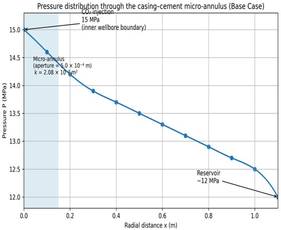
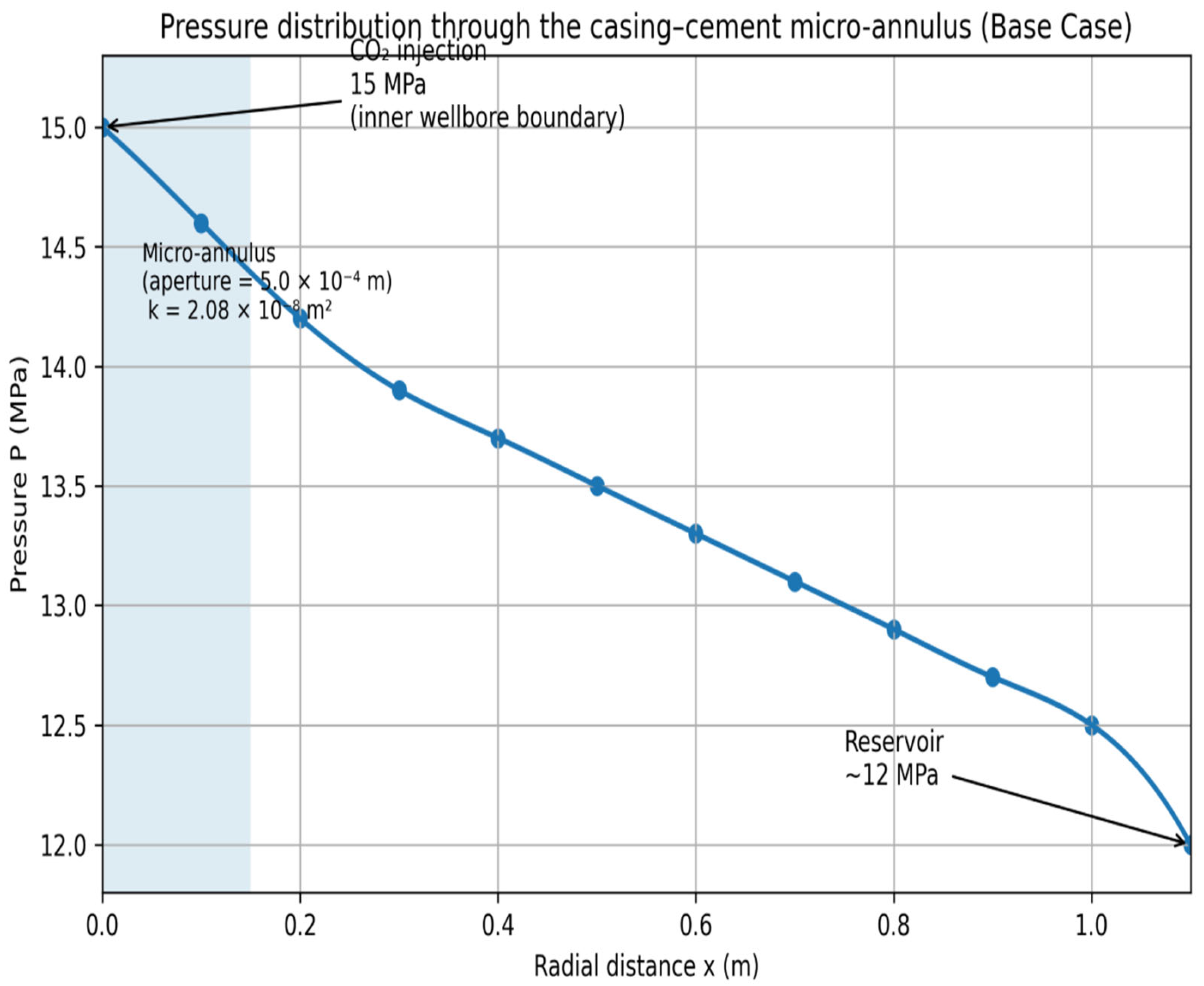
The base case simulation establishes the coupled THM response of the abandoned wellbore system under an injection pressure of 15 MPa, a reference reservoir pressure of 12 MPa, a prescribed micro-annulus aperture of 5.0 × 10⁻⁴ m, and a cement Young’s modulus of 18 GPa. For this configuration, the aperture-controlled micro-annulus permeability is 2.08 × 10⁻⁸ m2. The base case provides the reference condition for interpreting the subsequent pressure, aperture, and cement stiffness sensitivity analyses. As shown in Figure 3, the pressure field shows that CO2 pressurization is concentrated near the inner wellbore boundary and transmitted preferentially through the casing–cement interfacial pathway.
Figure 3.
Pressure distribution in the abandoned wellbore system at 500 s.
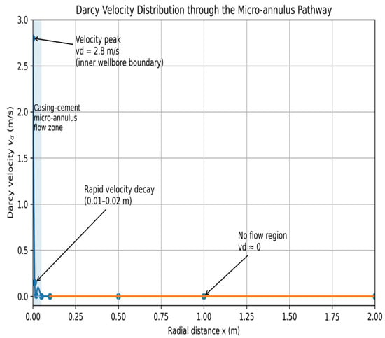
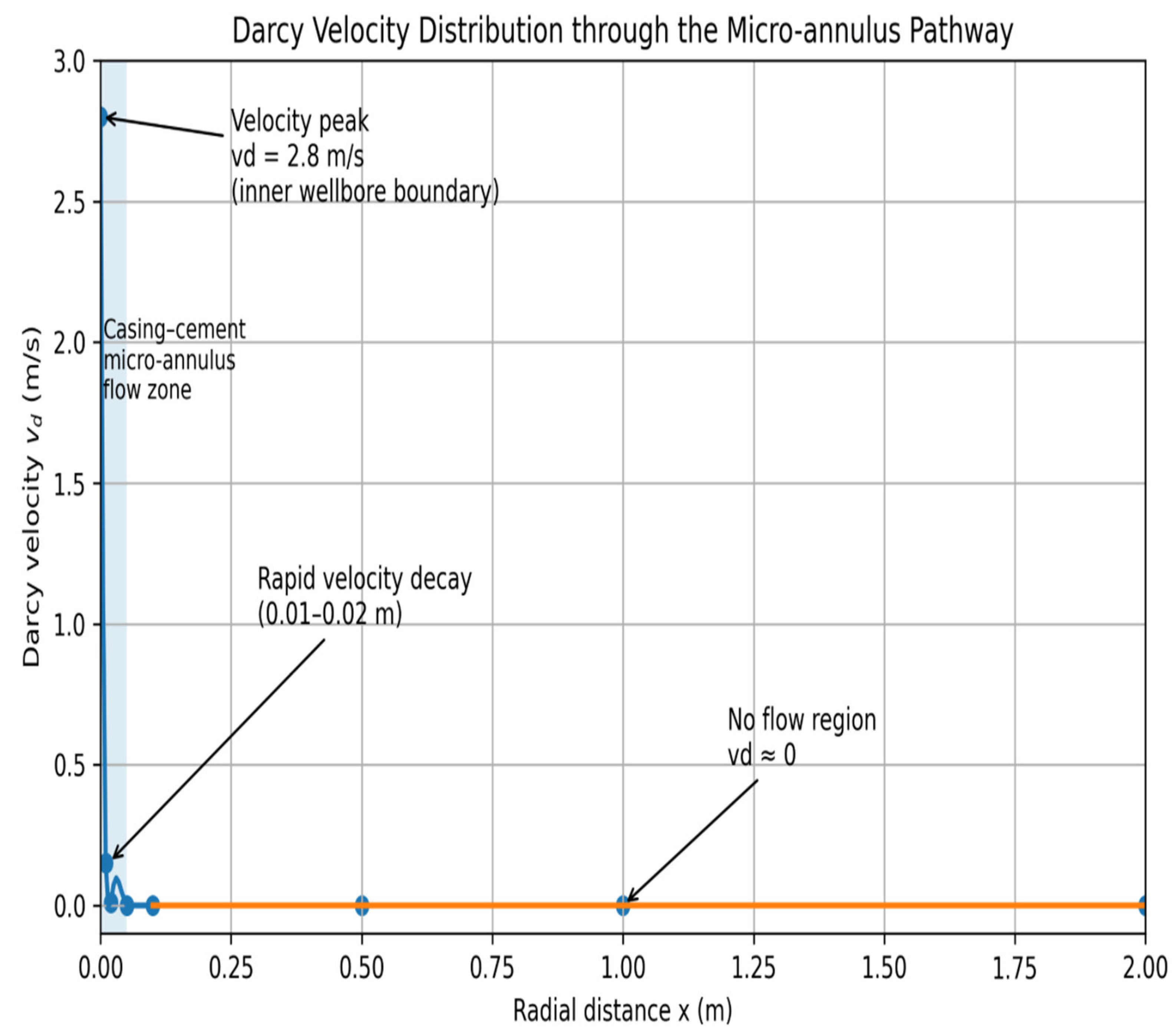
The maximum pressure reaches the imposed injection pressure of 15 MPa, confirming the correct transfer of the hydraulic boundary condition into the coupled domain. The pressure contrast between the injection boundary and the outer formation boundary drives CO2 migration, while the high permeability assigned to the micro-annulus causes the interface to act as the dominant leakage conduit rather than the cement matrix. The Darcy velocity distribution confirms this preferential leakage behavior. As shown in Figure 4, flow is localized along the micro-annulus, indicating that the assigned aperture produces a high-conductivity pathway at the casing–cement interface.
Figure 4.
Darcy velocity magnitude distribution at 500 s under base case conditions.
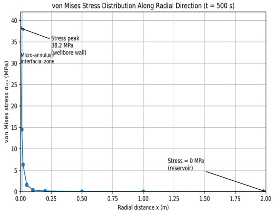
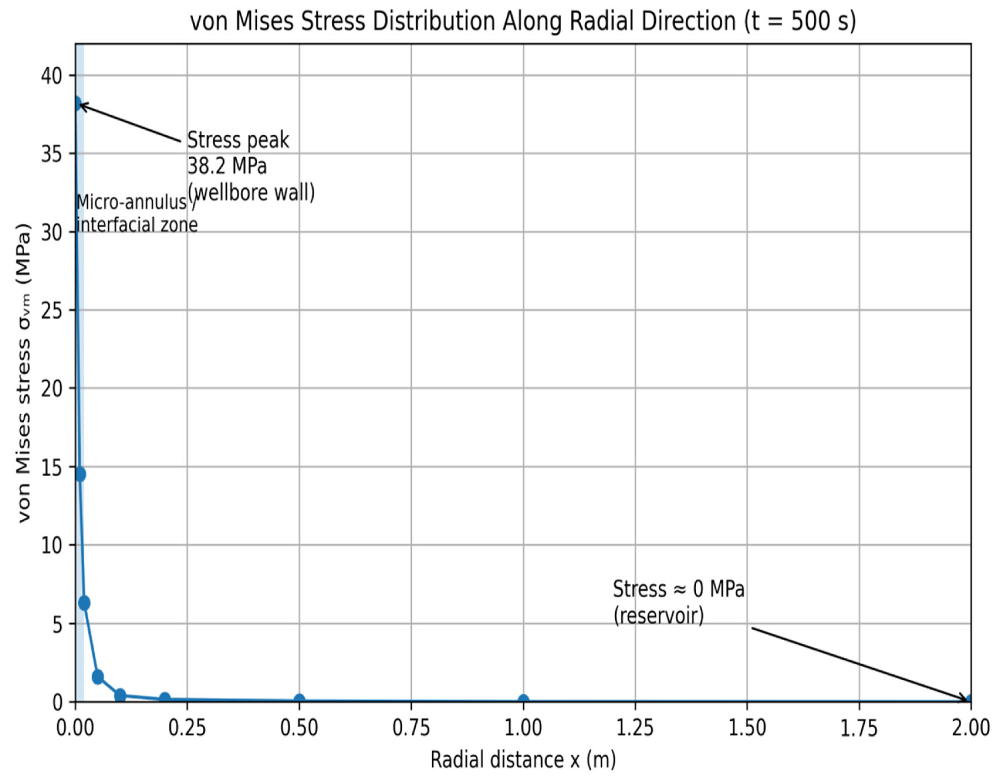
The base case average micro-annulus velocity at 500 s is 2.85 m/s. This result demonstrates that leakage is controlled primarily by the geometric conductance of the interfacial defect, rather than by the intrinsic permeability of the cement sheath. The temperature field is comparatively smooth relative to the pressure and velocity distributions. Although heat transfer is included in the coupled model, the early-time response shows limited thermal redistribution under the current boundary and material conditions. Therefore, temperature contributes to the stress field through thermoelastic coupling but does not dominate the leakage response within the simulated sensitivity window. This result supports the focus of the sensitivity analysis on injection pressure, micro-annulus aperture, and cement stiffness. The mechanical response is characterized by localized von Mises stress around the wellbore assembly and the interfacial leakage pathway. As shown in Figure 5, at 500 s, the base case maximum von Mises stress is 33.52 MPa, while the maximum displacement is approximately 1.64 × 10⁻³ m.
Figure 5.
Von Mises stress distribution at 500 s under base case conditions.
The stress concentration results from the combined effects of CO2 pressurization, effective stress reduction in the porous domains, thermal contrast, and mechanical confinement around the casing–cement formation system. Overall, the base case establishes the main mechanism observed throughout the simulations: the micro-annulus controls hydraulic leakage through aperture-dependent conductance, whereas injection pressure and cement stiffness control the mechanical stress response. Since the aperture is prescribed in each case, changes in leakage velocity are interpreted as geometric aperture effects, while changes in von Mises stress represent pressure- and material-controlled mechanical response. The simulated THM response is consistent with previous coupled thermo-poroelastic wellbore studies. Hosking and Zhou [19] reported that pressure and temperature perturbations generated localized stress redistribution around the casing–cement system, with stress concentration developing near wellbore interfaces during coupled THM loading. Similar behavior is observed in the present simulations, where pressure propagation through the casing–cement assembly generates localized von Mises stress concentration around the micro-annulus region. This agreement supports the physical consistency of the coupled THM implementation used in the present study.
3.2. Effect of Injection Pressure on Stress Redistribution and Leakage Response
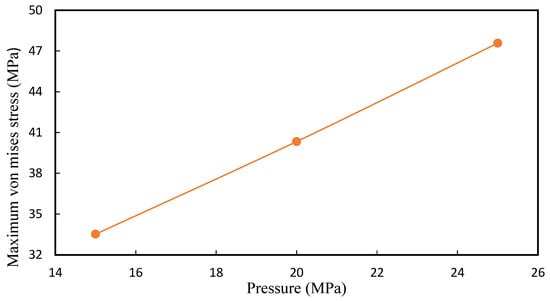
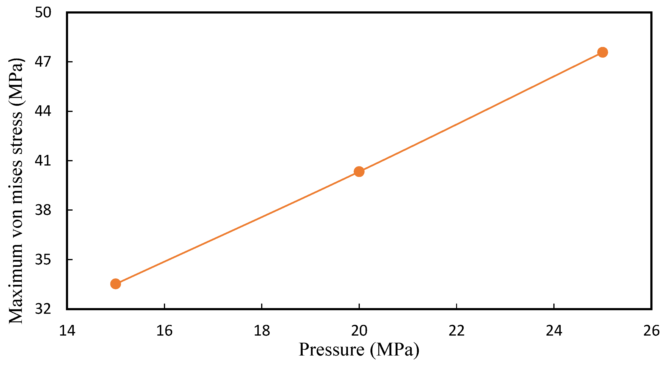
Injection pressure sensitivity was evaluated by varying pinj from 15 to 25 MPa while maintaining a fixed micro-annulus aperture of 0.5 mm and a cement Young’s modulus of 18 GPa. This case group isolates the effect of hydraulic loading on the coupled THM response without changing the assigned leakage pathway conductance. The results are summarized in Table 5 and Figure 6.
Table 5.
Effect of injection pressure on leakage and mechanical response at 500 s.
Figure 6.
Effect of injection pressure on maximum von Mises stress at 500 s.
The maximum pressure in each case matches the imposed injection pressure, confirming consistent hydraulic loading across the sensitivity set. Increasing pinj from 15 to 25 MPa increases the maximum von Mises stress from 33.52 to 47.58 MPa. This response shows that injection pressure primarily amplifies the mechanical loading of the casing–cement formation system. Higher pressure increases pore pressure perturbation near the wellbore, reduces effective confinement in the porous domains, and intensifies stress redistribution around the casing–cement interface. In contrast, the average micro-annulus velocity remains unchanged at 2.85 m/s across all pressure cases. This behavior is a direct consequence of the fixed-aperture formulation. Because the micro-annulus aperture is prescribed as b = δ0, its permeability remains fixed through keff = b2/12. Therefore, increasing injection pressure does not modify the hydraulic conductance of the leakage pathway in the present implementation. The pressure sensitivity therefore separates two mechanisms that are often coupled in damaged wellbore systems: hydraulic loading and leakage pathway conductance. Injection pressure controls the stress magnitude, whereas leakage velocity remains governed by the prescribed micro-annulus permeability. This result indicates that increasing injection pressure can elevate mechanical integrity risk even when the existing leakage pathway geometry is unchanged. This finding also defines the interpretation boundary of the present model. The explicit micro-annulus domain allows stress redistribution to be evaluated around an active leakage pathway, but the model does not simulate pressure-driven aperture growth. Therefore, the pressure cases provide a controlled reference for the mechanical effect of injection pressure independently of stress-dependent leakage pathway evolution. Accordingly, the pressure-independent leakage velocity observed in the present simulations is specific to the fixed-aperture formulation and should not be generalized to field wells in which the leakage pathway aperture evolves mechanically.
3.3. Effect of Micro-Annulus Aperture on Leakage Capacity
Micro-annulus aperture sensitivity was evaluated to quantify how the prescribed opening of the casing–cement interfacial pathway controls CO2 leakage capacity. The injection pressure and cement Young’s modulus were fixed at 15 MPa and 18 GPa, respectively, while the micro-annulus thickness was increased from 0.5 to 1.0 mm. This case group directly examines the hydraulic consequence of the aperture-controlled permeability formulation. The results are summarized in Table 6.
Table 6.
Effect of micro-annulus aperture on leakage and mechanical response at 500 s.
Increasing the micro-annulus thickness from 0.5 to 1.0 mm increased the effective permeability from 2.08 × 10⁻⁸ to 8.33 × 10⁻⁸ m2. This fourfold increase follows directly from the aperture–permeability relationship because keff scales with b2. The corresponding average Darcy (superficial) velocity increased from 2.85 to 11.42 m/s, also approximately fourfold. These values represent the hydraulic response predicted by the prescribed aperture-controlled leakage formulation. The strong sensitivity of leakage response to aperture is consistent with laboratory observations reported by Stormont et al. [17] and Corey et al. [31], who demonstrated that relatively small changes in hydraulic aperture produced substantial changes in gas transmissivity along cement–casing interfaces. Although the aperture values considered in the present study represent a more severe leakage scenario than laboratory-scale defects, both studies indicate that leakage behavior is primarily controlled by micro-annulus geometry rather than by cement matrix permeability. This confirms that leakage capacity in the present model is governed primarily by the geometric conductance of the micro-annulus rather than by the intrinsic permeability of the cement sheath. Increasing injection pressure intensified von Mises stress but did not change the average micro-annulus velocity because the aperture was fixed. By contrast, increasing the aperture directly increased keff and produced a strong hydraulic response. This contrast demonstrates that injection pressure and micro-annulus aperture control different parts of the THM response: pressure governs mechanical loading, while aperture governs leakage conductance. The mechanical response also changes with aperture. When the micro-annulus thickness increased from 0.5 to 1.0 mm, the maximum von Mises stress decreased from 33.52 to 29.73 MPa. This reduction indicates that a wider leakage pathway modifies local stress redistribution around the casing–cement interface. Under the same injection pressure, the wider interfacial pathway provides greater hydraulic conductance and reduces localized mechanical concentration compared with the narrower micro-annulus case. Therefore, the most conductive leakage pathway does not necessarily correspond to the highest local stress concentration. This complex interplay between defect geometry and fluid initiation aligns with coupled finite element and experimental assessments of leakage threshold widths, which demonstrate that the mechanical stress state and resulting aperture dimensions jointly dictate the physical onset of structural leakage [32]. To further examine the interaction between hydraulic loading and leakage pathway geometry, a combined severe case was evaluated using pinj=25 MPa and δ0=1.0 mm. The result is compared with the base, high-pressure, and wide-annulus cases in Table 7. The combined case produced an average micro-annulus velocity of 11.42 m/s, identical to the wide-annulus case at 15 MPa. This confirms that leakage velocity remains controlled by aperture-dependent permeability, even when injection pressure is increased.
Table 7.
Combined pressure–aperture response at 500 s.
The mechanical response follows a different trend. At the same aperture of 1.0 mm, increasing injection pressure from 15 to 25 MPa increased the maximum von Mises stress from 29.73 to 41.60 MPa. However, the combined severe case still produced lower stress than the high-pressure narrow-annulus case, where the maximum von Mises stress reached 47.58 MPa. This indicates that high pressure intensifies mechanical loading, while a wider micro-annulus can reduce local stress concentration relative to a narrower interfacial defect. The combined comparison reinforces the main finding of this section: the most severe hydraulic leakage condition is not necessarily the most severe mechanical stress condition. Wider micro-annuli produce higher leakage velocity because of higher keff, whereas narrow micro-annuli under high pressure may generate stronger local stress concentration. Therefore, leakage capacity and mechanical stress concentration should be evaluated as separate integrity indicators. Overall, the aperture sensitivity demonstrates that micro-annulus thickness is the dominant hydraulic control in the present model. Because these predictions were obtained using a Darcy-flow formulation, the reported velocities should be interpreted as model-based hydraulic indicators for comparing aperture effects rather than direct estimates of field leakage under all flow regimes. Aperture-controlled permeability governs CO2 leakage capacity, whereas injection pressure mainly regulates the mechanical stress response. These results further indicate that injection pressure and micro-annulus aperture interact through the coupled THM formulation rather than acting independently. Injection pressure predominantly controls the mechanical response, whereas aperture governs the hydraulic response through the equivalent permeability, and their simultaneous variation determines the overall leakage behavior. The combined case behavior is also consistent with laboratory observations showing that micro-annuli remain highly conductive leakage pathways even under elevated stress conditions. Stormont et al. [17] reported persistent gas flow through cement-casing micro-annuli despite stress-induced changes in interface conditions, highlighting the dominant role of aperture-controlled conductance.
3.4. Effect of Cement Stiffness on Mechanical Integrity
Cement stiffness sensitivity was evaluated to determine how the cement sheath controls stress redistribution around the pre-existing micro-annulus. Cement Young’s modulus Ec was varied from 10 to 30 GPa, while injection pressure and micro-annulus aperture were fixed at 15 MPa and 0.5 mm, respectively. Because the leakage pathway aperture was unchanged, this case group isolates the mechanical influence of cement stiffness without altering the hydraulic conductance of the micro-annulus. The results are summarized in Table 8.
Table 8.
Effect of cement Young’s modulus on mechanical response at 500 s.
The maximum pressure and average micro-annulus velocity remain unchanged across the stiffness cases, confirming that the hydraulic loading and leakage pathway conductance are identical. Therefore, the observed changes in mechanical response can be attributed to the variation in cement stiffness rather than to differences in pressure or leakage capacity. The dominant response is the reduction in maximum von Mises stress with increasing cement stiffness. As Ec increased from 10 to 30 GPa, the maximum von Mises stress decreased from 39.73 to 28.14 MPa. This indicates that the stiffer cement sheath reduces local stress concentration around the casing–cement formation system under the same hydraulic and geometric conditions. Conversely, the lower-stiffness cement case produced the highest stress response, indicating greater mechanical susceptibility around the interfacial leakage pathway. The maximum displacement remained close to 1.64 × 10⁻³ m for all stiffness cases. Compared with von Mises stress, displacement is therefore a weaker indicator of cement-stiffness effects under the present boundary conditions. The stress response provides a clearer measure of how cement stiffness modifies mechanical integrity around the leakage pathway. Micro-annulus aperture controls leakage velocity through aperture-dependent permeability, whereas cement stiffness controls stress redistribution without changing leakage capacity. Therefore, a low-stiffness cement sheath may not increase leakage rate directly in the fixed-aperture model, but it can reduce the mechanical safety margin by increasing localized stress around the casing–cement interface. Overall, cement stiffness acts as a mechanical integrity control rather than a hydraulic leakage control in the present THM framework. Increasing Ec reduces peak von Mises stress, while leakage velocity remains unchanged because the micro-annulus conductance is fixed. This distinction is important for abandoned well assessment because leakage capacity and mechanical vulnerability may be governed by different parameters.
3.5. Mechanistic Implications and Model Limitations
The results indicate that hydraulic leakage capacity and mechanical integrity response are governed by different physical mechanisms within the coupled THM wellbore system. In the present fixed-aperture formulation, leakage behavior is controlled primarily by the hydraulic aperture of the micro-annulus, whereas stress redistribution is influenced mainly by injection pressure and cement stiffness. Consequently, the condition associated with the highest leakage potential does not necessarily correspond to the condition associated with the greatest mechanical loading. This distinction is important because leakage risk and structural integrity are frequently evaluated as a single response, despite being controlled by different processes. The mechanistic interpretation obtained in this study is consistent with both experimental and numerical investigations reported in the literature. Laboratory measurements by Stormont et al. [17] demonstrated the dominant role of micro-annulus geometry in controlling gas transmissivity along cement–casing interfaces, while Hosking and Zhou [19] showed that stress redistribution around wellbore interfaces is a critical factor governing integrity evolution. The agreement between the present results and these independent studies supports the physical validity of the proposed THM framework for evaluating leakage behavior and mechanical response in abandoned wellbores. From an engineering perspective, the findings suggest that abandoned well assessment should consider hydraulic and mechanical indicators independently. Wells containing wider pre-existing micro-annuli may present elevated leakage risk because of greater hydraulic conductance, even when local stress concentrations remain relatively moderate. Conversely, narrower interfacial defects subjected to elevated injection pressures may experience greater mechanical loading and an increased likelihood of interface degradation despite lower leakage velocities. Effective integrity assessment therefore requires simultaneous evaluation of leakage indicators, such as effective permeability and leakage velocity, together with mechanical indicators, such as stress concentration and deformation. These observations highlight the need to distinguish leakage capacity from structural integrity when evaluating long-term wellbore performance. The principal methodological contribution of the present study is the explicit representation of the micro-annulus as an independent aperture-controlled leakage domain within a coupled THM framework. Unlike approaches that represent leakage through equivalent cement permeability or prescribed boundary fluxes, the current formulation isolates the influence of micro-annulus geometry and enables direct evaluation of the interaction between hydraulic leakage behavior and stress redistribution. This approach provides greater physical transparency when assessing the role of interfacial defects in wellbore integrity. The interpretation of the results should be considered within the limitations of the implemented model. Although the present study employs deterministic simulations, numerical sensitivity was examined quantitatively through mesh refinement. The maximum von Mises stress changed by 1.73% between the coarse and normal meshes and by 3.82% between the normal and finer meshes, while maximum Darcy velocity at the surface remained unchanged at 6.7262 m/s. These results indicate that the predicted hydraulic response was mesh-independent over the investigated resolutions, whereas the stress prediction showed modest mesh sensitivity. The deterministic sensitivity analyses presented in Section 3.2, Section 3.3 and Section 3.4 further quantify the effects of injection pressure, micro-annulus aperture, and cement Young’s modulus on leakage velocity and mechanical response. However, these analyses do not constitute a formal probabilistic uncertainty quantification, because uncertainties in other parameters, including formation permeability, porosity, thermal properties, Biot’s coefficient, boundary conditions, and geological heterogeneity, were not varied. Future work should therefore apply probabilistic or global sensitivity methods to quantify their combined effects on CO2 leakage and wellbore integrity. The micro-annulus is assumed to be pre-existing and hydraulically active throughout the simulation, and its aperture remains fixed during each sensitivity case. Consequently, the model does not represent interface initiation, tensile or shear debonding, displacement-dependent aperture evolution, or stress-dependent permeability changes. The axisymmetric geometry also assumes circumferential uniformity of the wellbore components and the micro-annulus. Real abandoned wells may contain azimuthally heterogeneous micro-annuli, casing eccentricity, irregular cement-sheath thickness, and discrete bonded or unbonded contact regions. These features may generate localized leakage pathways and stress concentrations that cannot be captured by the present model. Their explicit representation would require a non-axisymmetric cross-sectional or fully three-dimensional formulation with spatially variable interface geometry and, where appropriate, contact mechanics. Furthermore, the current framework does not account for cyclic plasticity or cumulative plastic strains within the cement sheath, which have been shown experimentally via fiber Bragg grating (FBG) sensors to induce progressive tensile radial stresses during unloading cycles that drive interface debonding [32]. The absence of velocity variation in the pressure and cement stiffness sensitivity analyses should therefore be interpreted as a consequence of the fixed-aperture assumption rather than as evidence that these parameters cannot influence leakage behavior under field conditions. The single-phase formulation does not account for water saturation within the micro-annulus. Under field conditions, water may reduce CO2 mobility through phase-relative permeability and may temporarily restrict gas invasion through capillary entry resistance or capillary locking. The magnitude of these effects depends on aperture distribution, surface roughness, wettability, interfacial tension, pressure history, and saturation state. Accordingly, the calculated single-phase leakage values should be interpreted as upper-bound hydraulic capacity estimates for a CO2-accessible pathway rather than as direct field leakage rates. Additional limitations include the neglect of geochemical alteration and self-sealing processes and the use of a synthetic wellbore configuration rather than site-specific field data. Future developments should incorporate stress-dependent aperture evolution, coupled damage mechanics, multiphase CO2–brine flow, and field-scale wellbore characterization to improve predictive capability and applicability to operational CO2 storage projects.
4. Conclusions
This study developed a coupled THM model to investigate CO2 leakage through a pre-existing micro-annulus at the casing–cement interface of an abandoned wellbore. The model explicitly represents the micro-annulus as an aperture-controlled leakage domain, enabling hydraulic leakage behavior and mechanical integrity response to be evaluated within the same framework. The results show that hydraulic leakage capacity and mechanical response are governed by different controlling mechanisms. Micro-annulus aperture primarily controls leakage conductance, whereas injection pressure and cement stiffness primarily influence stress redistribution. A key finding is that the condition producing the highest leakage capacity does not necessarily produce the highest mechanical stress concentration, indicating that leakage risk and mechanical vulnerability should be assessed as separate integrity indicators. The model assumes a pre-existing fixed-aperture micro-annulus and does not include interface debonding, stress-dependent aperture evolution, multiphase CO2–brine flow, or geochemical alteration. Future work should incorporate these processes to extend the framework toward a fully coupled stress-dependent leakage assessment for geological carbon storage applications.
Author Contributions
Conceptualization, B.M.S.; Methodology, B.M.S. and D.S.C.; Software, B.M.S.; Formal analysis, L.L. and B.M.S.; Investigation, B.M.S., C.J.S. and E.G.S.; Writing—original draft, B.M.S.; Writing—review & editing, L.L., B.M.S. and D.S.C.; Supervision, L.L., B.M.S., D.S.C., C.J.S. and E.G.S. All authors have read and agreed to the published version of the manuscript.
Funding
This research received no external funding.
Data Availability Statement
The original contributions presented in this study are included in the article. Further inquiries can be directed to the corresponding author.
Conflicts of Interest
Author Emmanuel Gilbert Simon was employed by the company Tanzania Petroleum Development Corporation (TPDC). The remaining authors declare that the research was conducted in the absence of any commercial or financial relationships that could be construed as a potential conflict of interest.
References
- Carroll, S.A.; Iyer, J.; Walsh, S.D. Influence of chemical, mechanical, and transport processes on wellbore leakage from geologic CO2 storage reservoirs. Acc. Chem. Res. 2017, 50, 1829–1837. [Google Scholar] [CrossRef] [Scilit] [PubMed]
- Ajayi, T.; Gomes, J.S.; Bera, A. A review of CO2 storage in geological formations emphasizing modeling, monitoring and capacity estimation approaches. Pet. Sci. 2019, 16, 1028–1063. [Google Scholar] [CrossRef] [Scilit]
- Kelemen, P.; Benson, S.M.; Pilorgé, H.; Psarras, P.; Wilcox, J. An overview of the status and challenges of CO2 storage in minerals and geological formations. Front. Clim. 2019, 1, 9. [Google Scholar] [CrossRef] [Scilit]
- Neagu, D.D.; Dumitrache, L.; Suditu, S.; Branoiu, G.; Chis, T.-V.; Eparu, C.N.; Stan, I.G.; Prundurel, A.P.; Simion, P.C. A Technical Feasibility Assessment Using Reservoir Simulation for CO2 Storage in Sarmatian Formations of the Getic Platform, Romania. Sustainability 2026, 18, 6932. [Google Scholar] [CrossRef] [Scilit]
- Enriquez, H.C.; Dick, H.; Salter, R.; Lee, S. Establishing Best Practices for Well Abandonment in CCS. In Proceedings of the International Petroleum Technology Conference, IPTC, Dhahran, Saudi Arabia, 12 February 2024; p. D021S081R002. [Google Scholar]
- DiGiulio, D. Understanding, Evaluating, and Remediating Leakage from Abandoned Oil and Gas Wells During Geological Storage of Carbon Dioxide; Center for Applied Environmental Science, Environmental Integrity Project: Washington, DC, USA, 2024. [Google Scholar]
- Kaya, G.; Dahi Taleghani, A. Integrity issues for underground gas storage wells. ASME Open J. Eng. 2025, 4, 040804. [Google Scholar] [CrossRef] [Scilit]
- Torsæter, M.; Todorovic, J.; Lavrov, A.; Gawel, K.; Lund, H.; Roy, P.; Carroll, S. Avoiding damage of CO2 injection wells caused by temperature variations. Energy Procedia 2017, 114, 5275–5286. [Google Scholar] [CrossRef] [Scilit]
- Citalingam, K.; Zeinijahromi, A.; Salmachi, A.; Xie, Q. Wellbore interface and cement defects in CO2 geological storage: A review. Greenh. Gases Sci. Technol. 2026, 16, 332–352. [Google Scholar] [CrossRef] [Scilit]
- Alsubaih, A.; Sepehrnoori, K. Comprehensive analysis of cement integrity in CO2 storage wells: Integrating thermomechanical and chemical effects. Geoenergy Sci. Eng. 2025, 256, 214152. [Google Scholar] [CrossRef] [Scilit]
- Shi, X.; Zhang, C.; Gupta, K.; Ambat, R.; Wu, M. Risks of cement and rock-cement-metal interface degradation in geological carbon sequestration reservoirs: Mechanisms, influencing factors and mitigation measures. Carbon Capture Sci. Technol. 2025, 15, 100419. [Google Scholar] [CrossRef] [Scilit]
- Li, X.-R.; Gu, C.-W.; Ding, Z.-C.; Feng, Y.-C. THM coupled analysis of cement sheath integrity considering well loading history. Pet. Sci. 2023, 20, 447–459. [Google Scholar] [CrossRef] [Scilit]
- Zhang, W.; Eckert, A. Micro-annulus generation under downhole conditions: Insights from three-dimensional staged finite element analysis of cement hardening and wellbore operations. J. Rock Mech. Geotech. Eng. 2020, 12, 1185–1200. [Google Scholar] [CrossRef] [Scilit]
- Eissa, B.; Watson, M.; Arbad, N.; Emadi, H.; Thiyagarajan, S.; Baig, A.R.; Shahin, A.; Abdellatif, M. A Review of Key Challenges and Evaluation of Well Integrity in CO2 Storage: Insights from Texas Potential CCS Fields. Sustainability 2025, 17, 5911. [Google Scholar] [CrossRef] [Scilit]
- Yan, Y.; Guan, Z.; Han, L.; Liu, Y. Coupled thermo-hydro-mechanical analysis of perforated cement sheath integrity during hydraulic fracturing. J. Pet. Sci. Eng. 2022, 218, 110950. [Google Scholar] [CrossRef] [Scilit]
- Moghadam, A.; Castelein, K.; Ter Heege, J.; Orlic, B. A study on the hydraulic aperture of microannuli at the casing–cement interface using a large-scale laboratory setup. Geomech. Energy Environ. 2022, 29, 100269. [Google Scholar] [CrossRef] [Scilit]
- Stormont, J.C.; Fernandez, S.G.; Taha, M.R.; Matteo, E.N. Gas flow through cement-casing microannuli under varying stress conditions. Geomech. Energy Environ. 2018, 13, 1–13. [Google Scholar] [CrossRef] [Scilit]
- Ashena, R.; Ott, W.K. Micro-annulus vs Micro-channels. In Cement Bond Logs: Guidelines and Interpretation; Springer: Cham, Switzerland, 2025; pp. 59–70. [Google Scholar]
- Hosking, L.J.; Zhou, X. Damage modeling of CO2 injection well interfaces under coupled thermal, hydraulic and mechanical behavior. Deep Undergr. Sci. Eng. 2025, 4, 762–776. [Google Scholar] [CrossRef] [Scilit]
- Yin, F.; Hou, D.; Liu, W.; Deng, Y. Novel assessment and countermeasure for micro-annulus initiation of cement sheath during injection/fracturing. Fuel 2019, 252, 157–163. [Google Scholar] [CrossRef] [Scilit]
- Roy, P.; Morris, J.P.; Walsh, S.D.; Iyer, J.; Carroll, S. Effect of thermal stress on wellbore integrity during CO2 injection. Int. J. Greenh. Gas. Control 2018, 77, 14–26. [Google Scholar] [CrossRef] [Scilit]
- Zulkipli, S.N.F.; Razak, M.Z.A.; Johare, D. Reinventing Well Integrity and Zonal Isolation in Well Abandonment Through Prudent Subsurface Data Integration and Novel Dual Casings Cement Bond Assessment Technology. In Proceedings of the International Petroleum Technology Conference, IPTC, Dhahran, Saudi Arabia, 12 February 2024; p. D031S107R005. [Google Scholar]
- Wang, Y.; Dusseault, M.B. A coupled conductive–convective thermo-poroelastic solution and implications for wellbore stability. J. Pet. Sci. Eng. 2003, 38, 187–198. [Google Scholar] [CrossRef] [Scilit]
- Nagel, N.; Sanchez-Nagel, M.; Zhang, F.; Garcia, X.; Lee, B. Coupled numerical evaluations of the geomechanical interactions between a hydraulic fracture stimulation and a natural fracture system in shale formations. Rock Mech. Rock Eng. 2013, 46, 581–609. [Google Scholar] [CrossRef] [Scilit]
- Yang, D.; Xu, S.; Liu, B.; Guo, Y.; Wang, Y.; Wen, K.; Jia, Y.; Li, Q.; Nie, J. A critical review of pore pressure–stress coupling: Mechanisms, modeling, and implications for subsurface energy systems. Geoenergy Sci. Eng. 2026, 260, 214388. [Google Scholar] [CrossRef] [Scilit]
- Meng, M.; Frash, L.P.; Carey, J.W.; Mehana, M.; Li, W.; Chen, B. Effect of stress-dependent microannulus aperture on well leakage. J. Rock Mech. Geotech. Eng. 2024, 16, 1967–1976. [Google Scholar] [CrossRef] [Scilit]
- Al Ramadan, M.; Salehi, S.; Aljawad, M.S.; Teodoriu, C. Numerical modeling of gas migration through cement sheath and microannulus. ACS Omega 2021, 6, 34931–34944. [Google Scholar] [CrossRef] [Scilit] [PubMed]
- Yu, S.; Espinoza, D.N. Coupled THM Analysis of Long-term Cold CO2 Injection: Caprock Stress Evolution and Mechanical Integrity. In Proceedings of the ARMA US Rock Mechanics/Geomechanics Symposium, Santa Fe, NM, USA, 8–11 June 2025; p. D031S029R006. [Google Scholar]
- Doherty, B.; Vasylkivska, V.; Huerta, N.J.; Dilmore, R. Estimating the leakage along wells during geologic CO2 Storage: Application of the Well Leakage Assessment Tool to a hypothetical storage scenario in Natrona County, Wyoming. Energy Procedia 2017, 114, 5151–5172. [Google Scholar] [CrossRef] [Scilit]
- Orlic, B.; Chitu, A.; Brunner, L.; Koenen, M.; Wollenweber, J.; Schreppers, G.-J. Numerical investigations of cement interface debonding for assessing well integrity risks. In Proceedings of the ARMA US Rock Mechanics/Geomechanics Symposium, Seattle, WA, USA, 17–20 June 2018; p. ARMA–2018–1298. [Google Scholar]
- Carey, J.W.; Svec, R.; Grigg, R.; Zhang, J.; Crow, W. Experimental investigation of wellbore integrity and CO2–brine flow along the casing–cement microannulus. Int. J. Greenh. Gas. Control 2010, 4, 272–282. [Google Scholar] [CrossRef] [Scilit]
- Chen, S.; Zhang, S.; Shen, J.; Luo, Z.; Wang, L.; Yang, R. Generation of Microannulus at the Casing/Cement Sheath Interface under Cyclic Loading: A Full-Scale Experiment and Finite Element Method Simulation. SPE J. 2026, 31, 3003–3018. [Google Scholar] [CrossRef] [Scilit]

Disclaimer/Publisher’s Note: The statements, opinions and data contained in all publications are solely those of the individual author(s) and contributor(s) and not of MDPI and/or the editor(s). MDPI and/or the editor(s) disclaim responsibility for any injury to people or property resulting from any ideas, methods, instructions or products referred to in the content. |
© 2026 by the authors. Licensee MDPI, Basel, Switzerland. This article is an open access article distributed under the terms and conditions of the Creative Commons Attribution (CC BY) license.