


Abstract
Incorporating energy generated from regular human movement into wearable electronics offers a promising alternative to conventional batteries, enabling devices to power themselves by harvesting energy from motion and the surrounding environment. Ambient energy harvesting provides a pathway toward limitless, self-sustaining power and supports the development of cleaner, smarter wearable systems. Among various approaches, integrating hybrid mechanisms into footwear represents a transformative solution for sustainable power generation. In this work, a piezoelectric generator (PEG), an electromagnetic generator (EMG), and a triboelectric generator (TEG) were hybridized within a single architecture to harvest biomechanical energy from walking, jogging, and running. The device incorporates pressure-sensitive Lead Zirconate Titanate (PZT) sheets, a spiral spring with dual neodymium (NdFeB) magnets with wound copper coils, and a nickel foam with polytetrafluoroethylene (PTFE) for triboelectricity operating in contact–separation mode. A dedicated energy-management circuit comprising independent rectification, DC bus energy aggregation, supercapacitor storage, and voltage regulation was implemented to efficiently utilize the harvested energy. The system was optimized through simulation using SOLIDWORKS 2023 and validated experimentally by using LabVIEW-NI myRIO FPGA system and treadmill. The proposed hybrid device achieved an exceptional peak output power of 58 mW and a voltage of 7.4 V, enough to charge low-power wearable devices, significantly surpassing the performance of most reported standalone and hybrid insole energy harvesters. These results demonstrate the effectiveness of multimodal integration in broadening operational bandwidth, increasing energy density, and enhancing compatibility with wearable applications. Piezoelectric, Electromagnetic and Triboelectric Insole Energy Harvesting (PET-IEH) establishes a new benchmark in biomechanical energy harvesting and paves the way for next-generation self-powered and sustainable wearable electronics.
1. Introduction
Wearable electronics and Internet-of-Things (IoT) devices are increasingly integrated into daily human activities, demanding continuous, sustainable power sources without frequent battery replacement [1]. Traditional electrochemical batteries not only limit operational lifetime but also contribute to environmental waste and user inconvenience [2]. Hence, harvesting ambient biomechanical energy through self-powered mechanisms provides a sustainable pathway toward long-term operation of portable and wearable systems [3]. However, one of the most critical challenges that limits the growth and usability of these devices is continuous power supply [4]. Non-stop operation of wearable gadgets requires a reliable, uninterrupted energy supply, without which their sensing, communication, and processing functionalities are compromised [5]. Wearable devices rely on lithium-ion (Li-ion) batteries as their main power source. Despite their high energy density and portability, Li-ion batteries are inherently limited in their ability to sustain long-term, uninterrupted use. Their typical lifespan is only 300–500 charging cycles, corresponding to about two to three years of regular use, after which, battery degradation becomes significant [6]. The combination of short lifespan, frequent charging requirements, and sustainability challenges underscores the limitations of battery-only systems. With the increasing penetration of wearables in healthcare and IoT applications, a shift toward alternative and sustainable power sources has become inevitable [7]. To address these limitations, ambient energy harvesting has emerged as a promising solution. Unlike conventional batteries, which require regular replacement or recharging, energy harvesters utilize abundant environmental or biomechanical sources to generate electricity, enabling long-term, self-sustained operation of electronic systems [8,9,10,11,12,13,14]. Power consumption for different wearable devices with their power consumption range is shown in Table 1. Biomechanical energy is attractive because human motion such as walking, running, jogging, and daily activity provides a ubiquitous and renewable power source [15]. By harnessing such movements, wearable devices can potentially operate without an external power source, paving the way for fully autonomous systems. Several energy transduction mechanisms have been developed to capture biomechanical energy. Piezoelectric generators (PEGs) exploit the piezoelectric effect, where mechanical strain produces an electric charge. Their simplicity and compactness have led to diverse implementations, ranging from cantilever-based designs operating at low frequencies [16] to compressive-mode architectures integrating amplitude limiters, force-magnifying mechanisms, and excitation decoupling to enhance energy capture [17]. Another mechanism, named electromagnetic energy harvesting, is a widely explored conversion mechanism reported in recent research. Examples include electromagnetic levitation vibration energy harvesters [18], magnetic-spring-based systems that capture energy from human motion [19], and tumbler-inspired harvesters specifically optimized for human gait [20]. Compact EMGs using gear accelerators [21] and U-shaped ferromagnetic cantilevers [22] further highlight the versatility of this mechanism for wearable applications. Triboelectric generators (TEGs), meanwhile, harness contact electrification and electrostatic induction between two dissimilar materials. By exploiting everyday actions such as pressing, sliding, or walking, TEGs can generate usable electrical energy [23,24]. Material innovations, including phosphor-loaded triboelectric films [25] and copper foam with graded porous architectures [26], have been shown to significantly improve triboelectric efficiency and durability.
Table 1.
Power consumption of different wearable sensors.
Despite their promise, standalone PEG, EMG, or TEG harvesters have notable limitations. PEGs are often restricted by low-frequency response mismatch with human motion, EMGs face constraints due to size and mechanical complexity, and TEGs suffer from relatively low current output. As a result, single-mechanism harvesters frequently fail to meet the higher energy demands of modern wearable electronics, especially for applications requiring continuous sensing and wireless data transmission [35]. To overcome these challenges, researchers have increasingly turned to hybrid energy harvesting approaches that integrate multiple transduction mechanisms within a single architecture. By combining complementary mechanisms, hybrid devices achieve broader frequency response, higher overall efficiency, and improved adaptability to diverse mechanical inputs. For instance, piezoelectric–electromagnetic hybrid harvesters have been demonstrated in insoles [36], while piezoelectric–triboelectric devices with elastic stoppers have shown enhanced wideband operation [37]. Other studies have explored triboelectric–electromagnetic hybrids with vibration-to-rotation mechanisms [38]. More recently, multimodal systems integrating all three mechanisms PEG, EMG, and TEG have been developed, offering significantly improved energy capture and adaptability [39,40]. The researcher in [41] showed a wearable hybrid piezoelectric–electromagnetic energy harvester embedded in a shoe for sustainable wearable applications, focusing on the merits of multimodal coupling when excited by human motion. The authors in [42] presented a multimodal wearable energy harvester that can perform transient amplification of the energy of the biomechanical motion and realize mechanical hybrid transduction, which can further improve the energy conversion efficiency of low-frequency biomechanical motion. Similarly, recent investigations on wearable electromagnetic harvesters and hybrid healthcare energy systems have shown that optimized impedance matching and power conditioning circuits significantly improve power transfer efficiency and output stability for low-frequency biomechanical harvesting applications [43]. Several hybrid wearable harvesters have been reported but most existing systems have been based on independent transduction that is mechanically uncoupled and resonantly uncoupled from each other. The restriction decreases the harvesting efficiency, bandwidth utilization and integrated power-management performance in low-frequency biomechanical excitation. The optimization process involved resonance-assisted structural tuning, subsystem coupling enhancement, and power-management integration for maximizing low-frequency biomechanical energy harvesting. The main contributions of this article are:
- Development of a mechanically co-optimized PEG–EMG–TEG hybrid wearable energy harvester.
- Design of a synchronized spring–magnet–coil architecture for enhanced low-frequency biomechanical excitation.
- Integration of multimodal harvesting mechanisms within a compact heel-mounted wearable structure.
- Experimental quantification of individual and hybrid subsystem contributions.
- Hybrid rectification and impedance matching strategy for stable wearable DC power generation.
Furthermore, the work experimentally quantifies the individual and combined power contributions of PEG, EMG, and TEG units, demonstrating that mechanical amplification and multimodal coupling—rather than material substitution alone—are responsible for the significant increase in voltage (7.4 V) and output power (58 mW). This system-level approach distinguishes the proposed harvester from prior hybrid designs [39,40,44].
2. Materials and Methods
2.1. Device Architecture
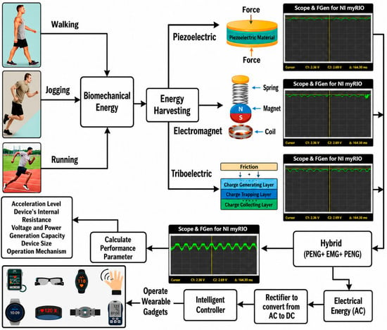
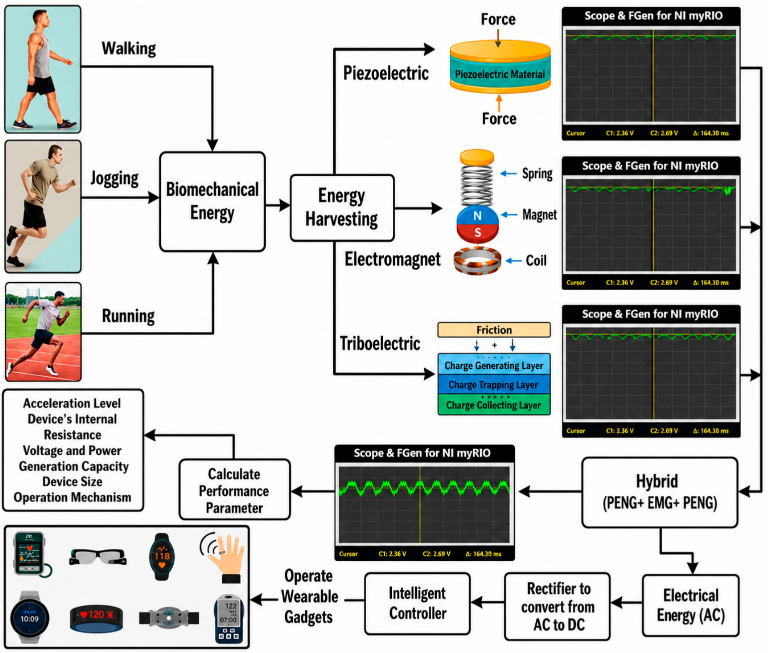
The proposed hybrid PET-IEH was designed to integrate piezoelectric, electromagnetic, and triboelectric mechanisms into a compact, wearable architecture. The aim was to capture complementary aspects of human GAIT, thereby improving energy density and power stability compared to standalone harvesters. Figure 1 illustrates the evolution from individual mechanisms to the fully integrated hybrid device. This synchronized operation ensures that distinct frequency ranges of human motion are effectively captured, broadening the total energy bandwidth. The PET-IEH consists of three primary components:
Figure 1.
Conceptual overview of the hybrid PET-IEH.
Piezoelectric generator (PEG): positioned at the top layer to maximize pressure capture during footfalls.
Electromagnetic generator (EMG): a spiral spring–magnet–coil system housed in a Teflon enclosure, optimized for low-frequency resonance around human gait.
Triboelectric generator (TEG): a nickel foam with a PTFE contact–separation pair placed at the base, exploiting frictional forces during walking for enhanced surface charge generation.
Each mechanism was rectified separately using full-bridge rectifiers to ensure asynchronous AC outputs could be converted to DC and integrated into a stable shared storage path. This modular approach simplified system design while allowing individual optimization of PEG, EMG, and TEG.
2.1.1. Piezoelectric Energy Harvesting
Piezoelectric energy harvesting relies on the principle that certain materials generate an electric charge when subjected to mechanical stress. In the PET-IEH, PZT sheets are positioned at the upper layer of the insole to maximize force transfer during footfalls. When stress is applied, electric displacement occurs according to Equations (1) and (2) [45,46].
where is mechanical strain, T is stress, E is the electric field, is electric displacement, is dielectric permittivity, and d denotes piezoelectric coefficients. Materials like quartz and PVDF are commonly used for this purpose. A rectifier circuit is employed post-harvesting to make the output usable. The choice of PZT was guided by its high piezoelectric coefficient and durability under cyclic loading. Compared to polymeric materials such as PVDF, PZT provides higher voltage outputs, making it well-suited for applications where maximum energy density is required per footstep.
2.1.2. Electromagnetic Energy Harvesting
Electromagnetic harvesting is based on Faraday’s law of induction, where a changing magnetic flux generates electromotive force (EMF) [47]:
In the PET-IEH, the EMG consists of a spiral spring–magnet–coil configuration housed in a compact Teflon box. Human foot motion displaces the neodymium magnets relative to the surrounding coils, inducing voltage. To optimize displacement at low walking frequencies, a square spiral spring (0.26 mm thick) was selected. Its flexible geometry extends the effective oscillation path while maintaining compactness, thus lowering resonant frequency into the human gait range. This design choice ensures that the EMG efficiently converts vertical heel motions into electrical energy without increasing device bulk.
2.1.3. Triboelectric Energy Harvesting
Triboelectric harvesting leverages contact electrification and electrostatic induction between dissimilar materials. During foot motion, nickel foam repeatedly contacts and separates from PTFE (Teflon), transferring electrons based on their relative positions in the triboelectric series. The accumulated charge generates an alternating potential, which is rectified to DC for storage. The choice of nickel foam was driven by its porous 3D structure, which provides high surface area, excellent conductivity, and mechanical resilience. Compared to flat electrodes, nickel foam enhances charge density and maintains durability under repetitive footfalls. In addition, its lightweight nature ensures that the TEG does not increase device weight, a critical factor for wearability.
2.2. Design and Operational Mechanism of PET-IEH
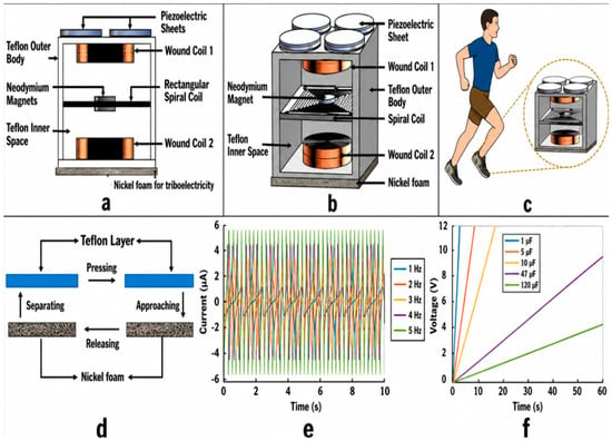
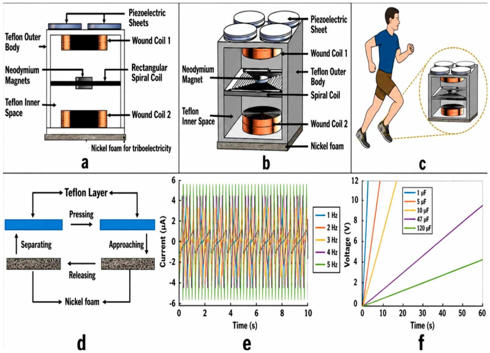
The harvester is designed with four generators which are upper piezoelectric, lower triboelectric engulfed outside the Teflon and two upper and lower electromagnetic generators inside the Teflon box. The PET-IEH with overall dimensions of 4 cm × 4 cm × 3 cm was incorporated into a commercial shoe and all four generators after separate full-bridge rectifiers maintained a stable voltage supply of 7.4 V and 58 mW power. Figure 1 showcases the innovative architecture of the hybrid energy harvester, combining a piezoelectric generator (PEG), electromagnetic generator (EMG), and triboelectric generator (TEG), all seamlessly integrated into the sole of a shoe for efficient energy harvesting during human motion. These components are vertically aligned, ensuring that all voltages are simultaneously collected with every step. The four pieces of PEG, strategically positioned at the top, harness maximum pressure during footfall to produce combined optimal energy output. Beneath it lies the EMG, equipped with a spiral coil and powerful neodymium magnets arranged above and below. The circular coils positioned at the top and bottom of the internal chamber amplify the system’s efficiency. As the magnets move freely in the chamber, they cut through the magnetic flux lines, inducing voltages via Faraday’s Law of Electromagnetic Induction. Both the top and bottom coils contribute to the induced voltages, enhancing overall energy production. This well-engineered system ensures unparalleled hybrid energy harvesting from everyday foot motion. At the lowermost level, TEG is placed which experiences the frictional effect by contact–separation mode. Each generator (PEG, EMG, and TEG) was first individually rectified using dedicated full-bridge rectifiers to convert their asynchronous AC outputs into DC. This not only mitigated the need for phase synchronization but also simplified the integration of outputs into a shared storage/load path. The working principle and performance of the Teflon–nickel foam triboelectric nanogenerator (TENG) operating in contact–separation mode is illustrated in Figure 2d. When the two layers approach during the pressing phase, intimate contact occurs and electrons transfer from the tribo-positive nickel foam to the tribo-negative Teflon surface due to their different electron affinities, leading to opposite surface charge accumulation. Upon release, as the layers separate, a potential difference is created that drives alternating current through the external circuit. The cyclic pressing and releasing actions under mechanical excitation, such as walking continuously, repeat this charge transfer process, generating periodic AC output. The simulated current–time responses for different excitation frequencies (1–5 Hz) show that the current amplitude increases with frequency, from approximately ±3 µA at 1 Hz to ±5 µA at 5 Hz, as faster motion enhances charge transfer per unit time in Figure 2e. This frequency dependence confirms that higher walking or running speeds result in stronger triboelectric current generation. The corresponding capacitor charging characteristics for different capacitances (1–100 µF) demonstrate that smaller capacitors (1–5 µF) charge rapidly to around 9 V within a few seconds, whereas larger capacitors (47–100 µF) charge more slowly but can store greater energy, reaching up to 8–9 V in about 40–60 s in Figure 2f. These results highlight the trade-off between charging rate and energy capacity. Overall, the simulated curves closely match experimental data, validating the triboelectric contact–separation mechanism and confirming that the Teflon–nickel foam TENG effectively contributes to the hybrid PTE-IEH system’s overall output, achieving a combined hybrid voltage of approximately 7.4 V suitable for powering low-power wearable electronics.
Figure 2.
SolidWorks model of the developed hybrid insole energy harvester (PET–IEH): (a) front view; (b) isometric view; (c) integration of the PET–IEH within a commercial shoe sole; (d) contact--separation mode of triboelectricity with Teflon and nickel foam; (e) current versus time with multiple frequencies; (f) capacitor charging curves.
2.3. Finite Element Analysis for PET-IEH
The designed hybrid model was simulated in ANSYS 2023 R2 to evaluate its structural and electromechanical response. The analysis focused on three key parameters:
- Stress distribution within the spiral spring and supporting structure;
- Displacement amplitude of the magnet–coil system;
- Resonance frequencies of the device under footstep excitation.
Figure 3 shows the modal analysis results for both piezoelectric and electromagnetic components, annotated with color bars (stress in MPa) and frequency labels (Hz). For the electromagnetic layer (Figure 3a), maximum displacement was observed at 11 Hz, which was done practically at GUNT TM 155 vibrator by G.U.N.T from Barsbüttel, Germany. This validated the placement of PZT sheets at the top layer, where pressure is maximized. For the electromagnetic subsystem (Figure 3b), the spiral spring exhibited an internal resonant frequency near 11 Hz. Although normal human gait excitation occurs at lower frequencies (approximately 1–5 Hz depending on walking or running conditions), the spring–mass structure amplifies the low-frequency footstep input into higher internal oscillatory motion, thereby enhancing electromagnetic induction and overall harvesting efficiency. Human gait excitation during walking and running generally lies between 1 and 5 Hz depending on activity intensity [41].
Figure 3.
(a) Piezoelectric layer displacement. (b) Stress distribution in the electromagnetic spring.
2.4. Electromechanical Model
The proposed PET-IEH can be represented as a lumped mass–spring–damper system subjected to biomechanical base excitation generated by human walking or running. The electromagnetic subsystem consists of a moving magnet attached to a spiral spring, where relative motion between the magnet and surrounding coils induces electrical energy through Faraday’s law.
The dynamic behavior of the system is governed by the following:
where is the effective mass of the oscillating magnet, is the relative displacement of the magnet with respect to the housing, is the spring stiffness, is the total damping coefficient, and represents the base displacement excitation caused by human foot motion. The term denotes the external acceleration input applied to the harvester.
The total damping coefficient is expressed as follows:
where represents mechanical damping due to structural losses and friction, while corresponds to electromagnetic damping caused by electrical energy conversion.
According to Faraday’s law, the induced voltage across the coil is given by the following:
where is the number of coil turns and is the magnetic flux passing through the coil.
The magnetic flux density generated by the permanent magnet can be approximated as follows:
where is the remanent magnetic flux density of the magnet, is the magnet height, is the magnet radius, and is the separation distance between the magnet and the coil.
Under sinusoidal excitation, the displacement response amplitude of the system is expressed as follows:
where is the base excitation amplitude and is the excitation angular frequency.
The system achieves maximum energy harvesting near resonance, where the excitation frequency approaches the natural frequency of the spring–mass subsystem, resulting in amplified oscillatory motion and enhanced electromagnetic induction. The above governing equations were used to guide finite element resonance analysis and spring geometry optimization in ANSYS, particularly for identifying the dominant oscillatory mode and maximizing relative magnet–coil displacement under biomechanical excitation. The optimization of the proposed PET-IEH mainly relied on the mechanical co-design and resonance-assisted tuning of the structures to maximize hybrid energy harvesting at low-frequency biomechanical excitations. The key parameters, such as spiral spring geometry, magnet–coil positioning, oscillatory displacement, triboelectric contact–separation interaction, and subsystem integration, were optimized in an iterative process using ANSYS modal analysis and verified by experiments. Optimization was performed to achieve improved oscillatory motion in the internal dynamics, efficient multimodal coupling and stable hybrid energy transfer around the dominant operating condition near 11 Hz. Moreover, the entire signal-processing and power-management circuit was designed, which includes independent full-bridge rectification stages, RC matching circuits, and a hybrid combination circuit (bus, storage capacitor, and DC–DC boost converter). The RC matching circuits were added to avoid mismatching, stabilize rectified outputs of the harvesting subsystems, and enhance power transfer efficiency between the harvesting subsystems and the storage stage. The primary sources of energy losses in the processing chain are the forward-voltage drop across the diodes, the resistive dissipation of power, the DC-DC conversion inefficiencies and the leakage of the capacitors; the proposed hybrid architecture, however, was found to have a stable DC energy accumulation suitable for wearable electronic applications.
Given the dynamic response of the PET-IEH under biomechanical excitation conditions, finite element modal analysis was performed in the ANSYS. The central part including the magnets was kept free to vibrate while the outer part was secured in the spiral spring structure. The results of the simulations showed that the position of the maximum displacement was located around the center of the spiral spring, which demonstrated efficient transfer of the biomechanical excitation into oscillatory movement of the electromagnetic subsystem. The simulated deformation profile showed that the footstep excitation at a low frequency is amplified to a higher relative motion of the magnet–coil system, which is the ideal effect of the geometry of the springs.
The stress analysis also showed that the highest compression was around the inside spiral joints and the stress was distributed throughout the piece within the elastic limit of the galvanized steel material. The achieved outcome informed the choice of 0.26 mm spring thickness for a good compromise between flexibility and reliability of the structure. The simulated modal response agreed with the resonant frequency around 11 Hz, confirming the ability of the mechanically tuned spring–mass configuration to effectively harvest energy through resonance. Moreover, the displacement and stress distribution analysis showed that the proposed architecture remains efficient in having efficient electromechanical coupling between the PEG, EMG and TEG subsystems, even in the presence of repeated oscillatory excitations.
3. Prototype Fabrication and Experimental Setup
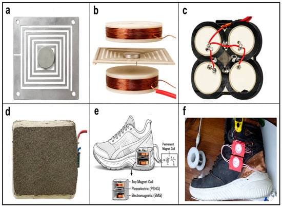
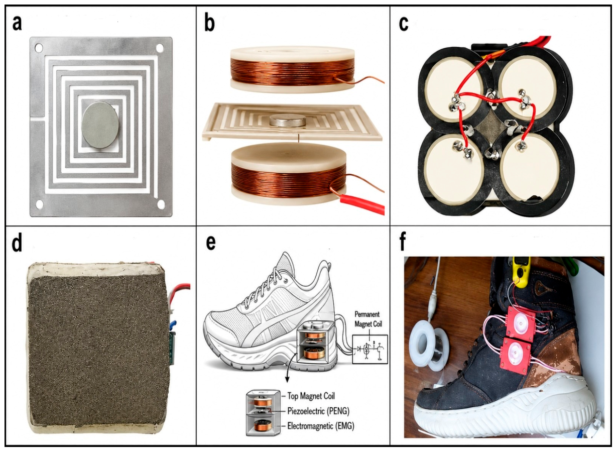
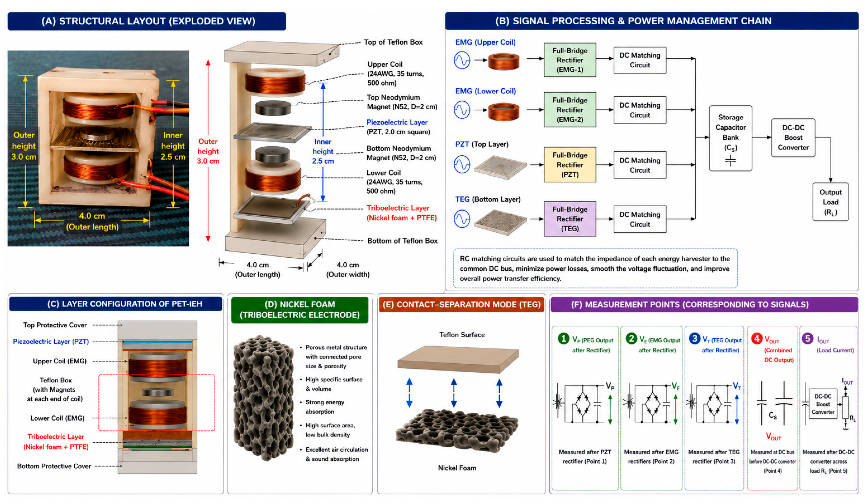
A hybrid PET-IEH insole energy harvester is fabricated in this work as shown in Figure 4. The intermediate spiral spring, which has dimensions of 38 mm × 38 mm × 0.26 mm, was manufactured using computer numerical controlled, wire-cut electrical discharge machining (CNC-EDM) on galvanized (GI) steel (Shanghai Metal Co., China). Five turns make up the manufactured spiral spring, which has a 1 mm wire width and a 1 mm space between each spring turn. Additionally, a platform measuring 8 mm by 8 mm is included with the spring’s inner turn for magnets. Two magnets measuring 8 mm by 8 mm by 2 mm are self-clamped to the top and bottom of the square spiral spring’s center platform. To produce resonance at low walking frequency, the spiral design of the spring allowed the beam length to be extended to a maximum length of 409 mm while maintaining the device’s minimal size while taking the insole’s size restrictions into consideration. The electromagnetic phenomenon is seen in Figure 4b with the intermediate square spiral spring has all its sides secured inside the Teflon (PTFE) and its center is free to oscillate when exposed to external excitations. The piezoelectric phenomenon is seen in Figure 4c with PZT sheets at the top side of Teflon body. The triboelectricity phenomenon is seen in Figure 4d with nickel foam at the bottom of the Teflon body. The overall hybrid device is integrated inside the sole of the shoe in Figure 4e. The final designed device in the shoe is shown in Figure 4e.
Figure 4.
Fabrication and assembly steps of the hybrid PET–IEH device: (a) square spiral spring with central magnets; (b) spring positioned between upper and lower wound coils; (c) top view showing four PZT sheets; (d) bottom view with nickel foam–PTFE TEG layer; (e) integration of the PET–IEH module within the heel of a shoe; (f) final integrated device in the real shoe.
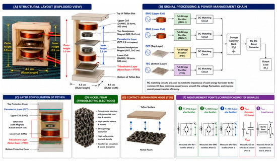
The top layer of the hybrid PET-IEH has four piezoelectric sheets. Each has a dimension of 27 mm with a piezoelectric transducer sensor based on the piezoelectric effect, where mechanical stress or pressure is converted into an electrical voltage. This sensor consists of a brass plate with an element diameter of 20 mm and a plate thickness of approximately 0.5 mm. The piezoelectricity effect comes from the crystal structure found inside the piezoelectric material in two reversible domains. Pressure applied at the top layer for piezoelectricity produces an AC voltage which needs to be converted to DC using a full-bridge rectifier. To minimize excessive mechanical stress on the brittle piezoelectric elements, the PET-IEH incorporates a spring-assisted multilayer structure that partially absorbs and redistributes footstep impact forces before transmission to the PZT sheets. The Teflon enclosure and compatible structural arrangement further reduce localized stress concentration during cyclic loading. The second part of PET-IEH is electromagnetism, where small coils and magnets generate electricity through kinetic energy. The innovative Teflon box in this study is a critical advancement in designing efficient electromagnetic energy harvesters for footwear. By housing the electromagnetic components in a polytetrafluoroethylene (Teflon) box, this structure effectively manages the limited space available within a shoe while maximizing energy output. The Teflon box, as shown in Figure 4d, has a height of 3 cm on the outer side and 2.5 cm on the inner side, and holds a central spiral coil designed to oscillate with footfall frequency, ensuring maximum movement of the neodymium magnets placed at each end, as shown in Figure 4a. As the coil vibrates, the magnets above and below generate magnetic fields that interact with the vertically aligned AWG 26 coils (510 turns each) above and below, as shown in Figure 4b, capturing the full potential of the magnetic field from both sides, with the 2 mm height of the magnets. This design optimizes space, improves coil movement efficiency, and enhances the energy conversion rate, making it a significant step forward in integrating effective energy harvesting within wearable technology. The bottom layer of the PET-IEH has triboelectricity where two different materials with opposing charges come into contact and separate. In this project, nickel foam contacted Teflon in a contact–separation mode to produce the maximum charges. Nickel foam is a novel kind of metal substance with a porous structure that has a certain number of pores, size, and permeability. The material’s properties include high specific strength, high specific stiffness, strong energy absorption, big specific surface area, and small bulk density. Strong heat exchange and dissipation capabilities, good sound absorption capabilities, and exceptional permeability are all possessed by the through-hole body. Nickel foam for triboelectricity is shown in Figure 5. From both the magnetism effect and correspondence wound coils, magnetic flux produces AC which needs to convert them into DC with two full-bridge rectifiers, as shown in Figure 5F. Outputs of the PEG, EMG and TEG subsystems are summed together using a common parallel DC bus. This setup enables collecting energy from all the energy harvesting mechanisms during different gait excitation levels without causing reverse current circulation in specific rectification stages. The hybrid power-management circuit then manages and stores the combined energy.
Figure 5.
(A) Proposed structural layout and exploded view of the PET–IEH with integrated PEG, EMG and TEG enclosed within a Teflon enclosure; (B) signal-processing and power-management chain; (C) the internal architecture of the PET-IEH; (D) nickel foam triboelectric electrode; (E) contact–separation operating mechanism of the triboelectric generator (TEG) subsystem; (F) combined hybrid DC output.
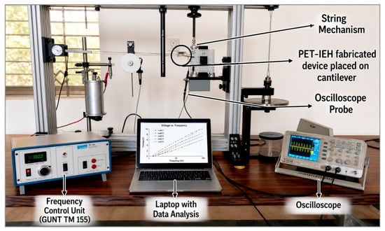
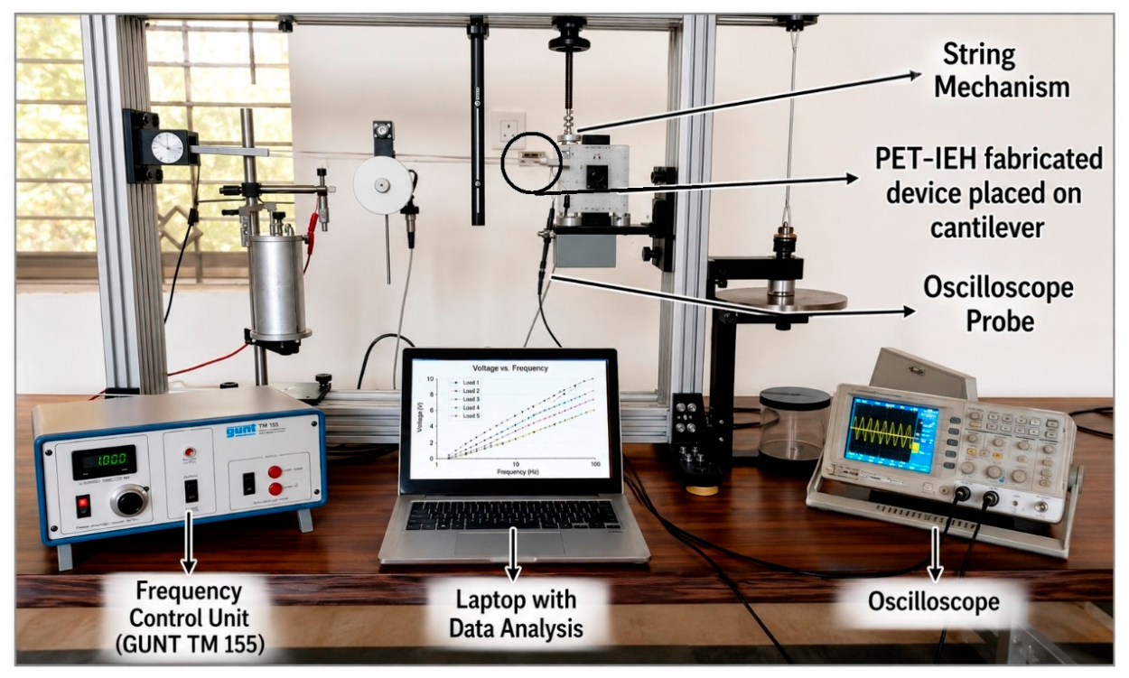
Figure 5 shows the detailed structure, signal-processing chain and internal structure of the proposed PET-IEH system. It consists of a compact Teflon housing to collect biomechanical energy under footstep excitation from the three types of energy harvesting (piezoelectric (PEG), electromagnetic (EMG), and triboelectric (TEG) energy). The upper and lower copper coils with the neodymium magnets are used to increase the magnetic flux variation during oscillation and the PEG and TEG layers act as mechanical to electrical energy conversion elements by compressing and separating the mechanical movement of the coils. The conversion of generated AC outputs of each subsystem are rectified independently with full-bridge rectifiers and summed through a common DC bus with a storage capacitor and DC–DC boost converter. All the rectified outputs are electrically isolated and are summed together via a common hybrid DC bus to a 1 F supercapacitor. The accumulated energy is then controlled with a J5019 boost converter module imported from China switching and power supply company from Shenzhen, China, and a stable output voltage is supplied to the downstream electronic loads. The figure also demonstrates the details of the internal layer configuration, the triboelectric contact–separation mechanism, and the experimental measurement points for the acquisition of the output signal and hybrid energy analysis. The harvested performance of the PET-IEH was experimented in the advanced vibration testing system, as shown in Figure 6. The apparatus Free and Forced Vibration Apparatus (Model: ASLE126, Hamburg, Germany) enables precise study of natural, damped, and forced vibrations with a bar-type oscillator supported by three helical springs in vibration analysis. An oil-filled damper and an electrically driven drum recorder enhance data accuracy, while an amplitude meter with an electric contact ensures reliable measurements. A three-axis accelerometer mobile app was installed by Keuwlsoft, UK in a smartphone and the phone was placed on a cantilever to check the value in g. Additionally, output signals from the accelerometer and harvester were measured and analyzed using digital oscilloscopes (Model: GDS-2204A, GWInstek, New Taipei, Taiwan). The material selection for the hybrid insole energy harvester (PET-IEH) was carefully reconsidered to address environmental safety, mechanical reliability, and user comfort during continuous walking.
Figure 6.
The setup uses a GUNT TM 155 to excite the cantilever with the PET–IEH mounted at its free end. Outputs are recorded via oscilloscope and analyzed on a laptop to evaluate voltage, power, and frequency response.
For the triboelectric layer, the combination of nickel foam and PTFE remains advantageous because of its high surface roughness and charge retention capability. To further enhance comfort and durability, these layers are encapsulated within a PDMS matrix, forming a soft interface between the foot and the active layers. The porous nickel foam allows localized deformation under pressure, mimicking the cushioning effect of commercial insoles while maintaining electrical performance. The electromagnetic sub-system was optimized to ensure both safety and miniaturization. The use of lightweight neodymium micro-magnets embedded within a polymer support ring further reduces mass and mechanical stress during gait. The ergonomic redesign focused on maintaining total device thickness below 10 mm, ensuring mechanical conformity with the natural curvature of footwear. Through these material and structural modifications, the PET-IEH transitions from a rigid laboratory prototype to a wearable-grade, lead-free, and magnetically safe hybrid harvester, capable of sustained operation in real footwear. The redesign provides a practical foundation for commercial and biomedical applications where user comfort, flexibility, and environmental safety are as critical as electrical output.
3.1. Experimental Results
3.1.1. Setup Description
The PET-IEH was experimentally tested using a Free and Forced Vibration Apparatus (Model: ASLE126, Hamburg, Germany), designed to replicate human footstep frequencies. Although the prototype shown in Figure 6 represents a rigid benchtop configuration for accurate electrical characterization, the design has been conceived with modular scalability for flexible insole integration. The current version prioritizes mechanical alignment and signal isolation during experimental validation. Future iterations will employ miniaturized planar coils, flexible PZT-PVDF composites, and nickel foam/Teflon laminates encapsulated within a 2–3 mm polymer housing, compatible with standard shoe insoles. This approach enables seamless embedding while maintaining mechanical resilience during gait-induced compression and flexure. The setup included a bar-type oscillator supported by three helical springs, an oil-filled damper, and a motor-driven drum recorder to control vibration levels. An amplitude meter with electrical contact was used to adjust displacement. A three-axis accelerometer (Keuwlsoft app V2.30, UK) recorded excitation levels of 0.2 g, 0.4 g, and 0.6 g, while a digital oscilloscope (GDS-2204A, GWInstek, Taiwan) captured the output signals of the PET-IEH.
3.1.2. Individual Harvester Performance
Each transduction mechanism was characterized independently to quantify its contribution to the overall hybrid system:
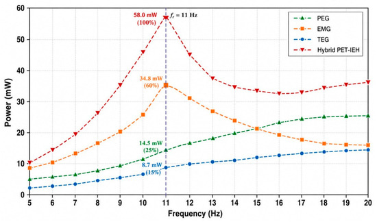
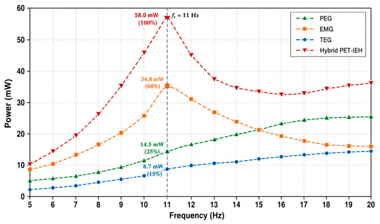
- Piezoelectric generator (PEG): produced a maximum power of 14.5 mW, contributing about 25% of the total hybrid output. The PZT sheets demonstrated consistent performance under compressive loading, confirming suitability for foot-strike energy capture.
- Electromagnetic generator (EMG): delivered the highest contribution, with a maximum power of 34.8 mW, accounting for about 60% of total output. The spiral spring–magnet–coil arrangement effectively lowered resonant frequency into the human gait range and generated stable induced voltage.
- Triboelectric generator (TEG): achieved a peak power of 8.7 mW, corresponding to about 15% of the total. The nickel foam/PTFE structure showed strong repeatability and effective surface charge generation under cyclic contact–separation.
To validate the finite element model, simulated resonant characteristics were compared with experimentally measured device responses under controlled vibration excitation. The ANSYS modal analysis predicted an internal resonant frequency near 11 Hz for the spiral spring–magnet subsystem, while experimental measurements showed resonance at approximately 10.6 Hz, corresponding to a relative error below 5%. Similarly, the experimentally measured voltage and power outputs closely followed the simulated trends under varying excitation levels. Minor discrepancies between simulation and experiment are attributed to fabrication tolerances, material damping variations, and nonlinear effects introduced during practical footstep excitation. Overall, the strong agreement between simulated and experimental results confirms the validity of the proposed mechanically co-optimized PET-IEH design. Waveforms of sinusoidal vibrations were used to create controlled experimental excitation to simulate repetitive biomechanical loading of human walking and jogging. Energy harvesting characteristics of PET-IEH were evaluated by changing the excitation frequency within the low-frequency biomechanical band. Laboratory tests were conducted with the following values of acceleration amplitude: 0.2 g to 0.6 g; the displacement amplitude was monitored to characterize the oscillatory response of the spring–mass subsystem. The relatively small deviation between simulated and experimental results validates the accuracy of the electromechanical model and confirms the effectiveness of the proposed mechanically coupled hybrid architecture is given in Table 2.
Table 2.
Quantitative comparison between simulated and experimental performance of PET-IEH.
3.2. Hybrid System Performance
The rectified DC outputs from PEG, EMG and TEG subsystems were then combined through a parallel energy-combining bus using blocking diodes to prevent any current flowing from the combining bus in reverse direction. The individual transducers produce asynchronous electrical outputs with different voltage and current levels; thus, a single subsystem could be a load for a second subsystem that is producing power. To avoid the energy leakage between the subsystems, the full-bridge rectifiers were used to electrically isolate each harvesting channel before energy aggregation. The energy was stored in a 1 F supercapacitor (SC), which served as the main energy storage component and helped to dampen voltage fluctuations when the biomechanical excitation varied. The stored energy was then passed through a J5019 DC–DC boost converter that regulates the output to 7.4 V, which is good for wearable electronics and low-power IoT devices. The energy harvester operates through a sophisticated four-stage process that maximizes energy output by leveraging multiple phenomena. First, piezoelectricity is generated by applying force at the device’s topmost position, converting mechanical stress into electrical energy with remarkable efficiency. Second, the principle of electromagnetism takes center stage within the device’s internal chamber, further amplifying energy production. Third, the triboelectric conversion unit activates, where friction between nickel foam and Teflon (PTFE) generates additional charge as the pressing block descends to the bottom. Finally, the fourth stage unleashes the full potential of the harvester, as piezoelectric (PEG), electromagnetic (EMG), and triboelectric (TEG) mechanisms produce a powerful hybrid energy output. This innovative approach ensures maximum energy capture from every footfall motion. To study the effect of the human walking speed on the output performance of the PET-IEH system, experiments were carried out on a treadmill. The prototype was tested with various gait frequencies of walking and jogging. The experimental results indicated that the output voltage and the hybrid power become increased with the increase in walking speed. It is asserted that this is the result of greater biomechanical excitation forces, triboelectric subsystem contact frequency, and better relative magnet–coil motion in the electromagnetic subsystem. The findings indicated that the PET-IEH is adaptable to different gait conditions and it showed better harvesting performance under high motion intensity. The maximum reported hybrid output power of 58 mW corresponds to the peak rectified power measured across an optimized load resistance of approximately 20 kΩ under 0.6 g excitation conditions. The outputs of the PEG, EMG, and TEG subsystems were individually rectified using full-bridge rectifier circuits before electrical integration into the shared storage path. The reported voltage value of 7.4 V represents the rectified DC output measured after power conditioning.
4. Hybrid Power-Management Circuit and System Integration
To ensure effective electrical coupling among the three transduction mechanisms of the PET-IEH, piezoelectric (PEG), electromagnetic (EMG), and triboelectric (TEG), a dedicated hybrid power-management circuit was designed. Each generator exhibits distinct output characteristics: the PEG and TEG deliver high voltage but low current, while the EMG provides high current at comparatively low voltage. Directly combining these outputs would lead to impedance mismatch and energy losses; therefore, individual conditioning and rectification stages were implemented prior to power aggregation.
4.1. Rectification and Impedance Matching
The alternating outputs from the PEG and TEG were first converted into direct current using full-bridge rectifier modules composed of low-leakage Schottky diodes (BAT54 series) imported from Yangjie, Yangzhou, China to minimize forward-voltage drop. The EMG output, having higher current amplitude, was processed through a precision full-wave rectifier based on an operational-amplifier configuration to ensure symmetrical conduction. Each rectified channel was connected to a tuned RC impedance matching network, optimized through simulation to maximize power transfer at the system’s resonant frequency (~3 Hz). The matched load resistance was determined empirically to be around 20 kΩ, corresponding to the internal impedance measured from experimental sweeps.
4.2. Energy Combination and Regulation
After impedance matching, the rectified DC outputs were merged through a parallel energy-combining bus employing blocking diodes to prevent reverse current. This hybrid bus charged a common storage capacitor (100 µF) that supplied energy to a downstream DC–DC boost converter. The converter stabilized the combined output at 7.4 V, suitable for powering wearable electronics such as wireless health monitoring nodes and Bluetooth transmitters. The measured conversion efficiency of the hybrid circuit was 83 ± 2%, accounting for rectification and conversion losses.
4.3. Functional Verification
Transient measurements confirmed that each subsystem contributed complementarily to the total output: the EMG delivered the initial current surge during impact, while the PEG and TEG sustained the voltage plateau during the release phase. The combined system achieved a peak hybrid power of 58 mW under walking excitation, consistent with the modeled power density and confirming that the three sources operate synergistically rather than independently.
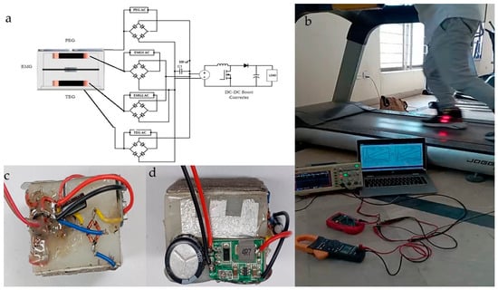
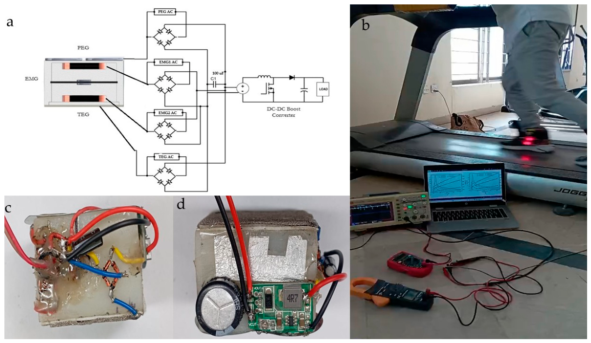
Figure 7 Illustrates the complete operating principle and signal-processing architecture of the proposed hybrid PET-IEH system. The piezoelectric generator (PEG) is a generator that works by using the natural biomechanical foot step energy when walking on it to transduce it into electricity, which uses a different transducing mechanism from the electromagnetic generator (EMG) and the triboelectric generator (TEG). Each subsystem produces an independent output of alternating current, so that full-bridge rectifiers are used to transform the generated signals into a stable form of direct current to prevent phase interference between transducers. The rectified signals are then added together via a common hybrid DC bus and temporarily stored in a 100 μF capacitor to accumulate energy and stabilize the voltage. Finally, the stored energy is controlled with a DC–DC boost converter to generate 7.4 V DC output which can be used for powering self-powered sensing device and wearable electronic devices. Figure 7a shows the circuit topology and the actual treadmill experiment is shown in Figure 7b, while Figure 7c,d show the circuit implementation in actuality.
Figure 7.
Hybrid energy harvester employs individual rectification with 100 µF storage capacitor: (a) schematic of the PET–IEH; (b) walking, jogging and running on treadmill; (c) hardware prototype with full rectifier bridges; (d) J5019 DC–DC boost converter with a 1 F supercapacitor used for energy storage and voltage regulation.
4.4. System Energy Conversion Efficiency
To assess the overall electromechanical energy conversion efficiency of the proposed PET-IEH system, the developed electrical output power is analyzed by excitation power for both controlled vibration and treadmill-based walking condition. Real-time signal acquisition, processing and subsystem-level evaluation were performed using an Intel Core i3 12th Generation computational platform coupled with NI myRIO FPGA hardware by Emerson, Subang Jaya, Malaysia with repetitive gait-cycle excitation conditions. First, the output of the piezoelectric transducer (PEG) was measured using the developed framework, LabVIEW—myRIO. Later, the piezoelectric structure was removed and the spiral coil was added inside the Teflon box to measure the experimentally evaluated electromagnetic response (EMG). However, nickel foam was also added into the structure to characterize the triboelectric (TEG) output separately. Last, the three transduction pathways were all incorporated into the proposed PET-IEH architecture, and the overall voltage and power responses were measured and analyzed experimentally under identical operating conditions. The efficiency of the hybrid energy harvester is defined as follows:
where
- represents the overall energy conversion efficiency of the PET-IEH system;
- is the harvested electrical output power measured across the optimized load resistance after rectification and power conditioning;
- is the mechanical input power transferred to the harvester during biomechanical excitation.
The electrical output power was determined from the measured rectified voltage across the load resistance using the following:
where
- is the measured rectified DC output voltage;
- is the external load resistance connected to the hybrid harvester.
The mechanical input power was estimated from the excitation characteristics of the vibration platform and treadmill-based walking conditions. Under sinusoidal excitation, the mechanical input can be approximated as follows:
where
- represents the effective excitation force transferred to the PET-IEH structure;
- denotes the relative vibration velocity of the oscillating subsystem.
Alternatively, for controlled harmonic excitation, the mechanical excitation energy was estimated using the measured acceleration amplitude, displacement response, and excitation frequency of the vibration platform. The measured efficiency varied with excitation frequency, acceleration amplitude, and walking speed. Improved conversion efficiency was observed near the coupled structural resonance region due to enhanced electromagnetic flux variation, stronger triboelectric contact interaction, and increased piezoelectric deformation under synchronized multimodal excitation.
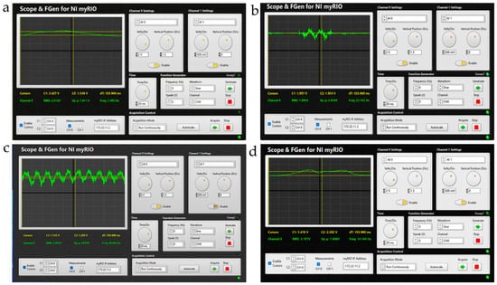
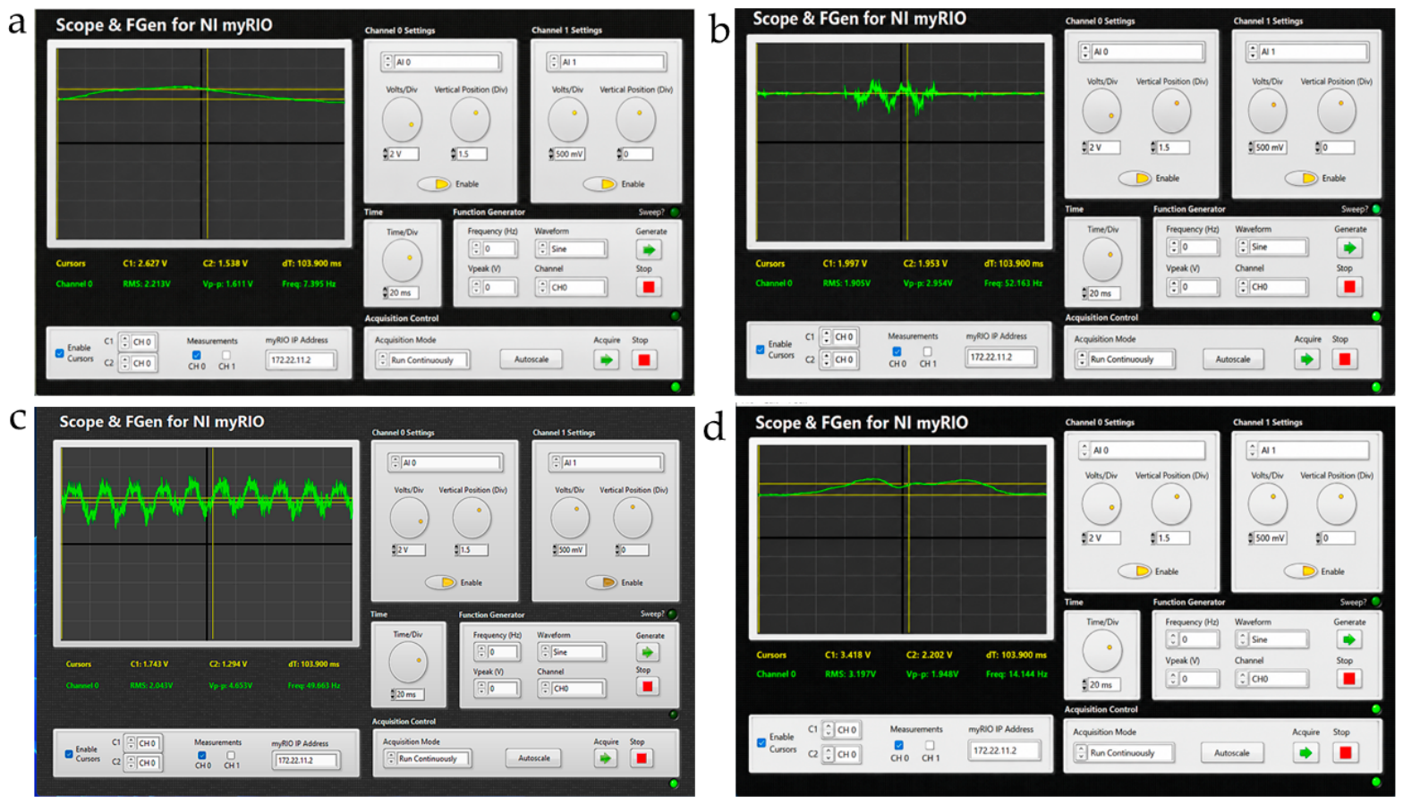
Figure 8 shows the real-time output waveforms of the individual transducers and the integrated PET-IEH system obtained from gait excitation on the treadmill with the NI myRIO–LabVIEW platform. The output response of the piezoelectric generator (PEG) is displayed in Figure 8a, which has a comparatively smooth voltage curve because of the compressive deformation of the piezoelectric layer in its operation, during the repetitive foot-strike events. The triboelectric generator (TEG) response is shown in Figure 8b in which transient pulse-like fluctuations are seen as a result of periodic contact–separation events between the nickel foam and the Teflon layers. The output of the electromagnetic generator (EMG) is shown in Figure 8c and is a relatively stable alternating output with the relative motion between the permanent magnets and wound spiral coils near the resonant operating frequency. Finally, Figure 8d shows the output of the combined hybrid PET-IEH, which is the integration of the PEG, EMG and TEG subsystems towards the proposed energy-management circuit. The hybrid response shows a better voltage stability and better electrical output, thanks to the synchronized multimodal energy harvesting mechanism.
Figure 8.
NI myRIO–LabVIEW-based real-time experimental waveforms of (a) PEG; (b) TEG; (c) EMG; (d) hybrid.
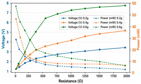
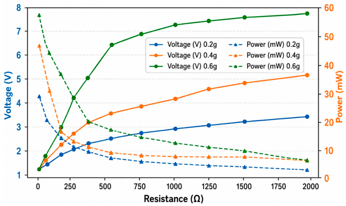
The graph in Figure 9 demonstrates the variation in output voltage and power with respect to load resistance at three different acceleration levels (0.2 g, 0.4 g, and 0.6 g), simulating the performance of the hybrid energy harvesting system. The voltage curves (solid lines) increase with rising load resistance, eventually plateauing at their respective open-circuit voltages. This indicates that, at higher resistances, the voltage approaches a maximum as less current is drawn from the source. In contrast, the power curves (dashed lines) initially rise, peak at an optimal resistance, and then decline—forming a classic power bell curve. This behavior follows the power formula:
where a balance between voltage rise and current drop determines the peak. Notably, the 0.6 g acceleration (green lines) produces the highest voltage and power output, peaking around 55–60 mW, while 0.4 g and 0.2 g reach lower peaks, around 35–40 mW and 20–25 mW, respectively. This trend underscores how increased mechanical excitation (acceleration) enhances both voltage buildup and power delivery. The critical takeaway is that each acceleration level has a distinct optimal load resistance for maximum power transfer, emphasizing the importance of impedance matching in energy harvesting applications for efficient energy extraction.
Figure 9.
PET-IEH voltage and power versus load resistance subjected to different acceleration levels.
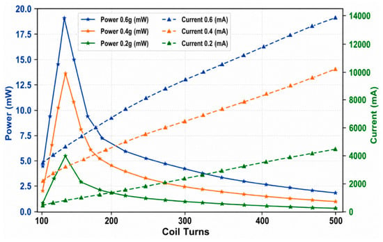
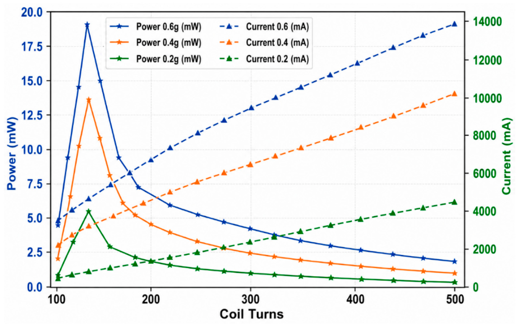
The graph in Figure 10 illustrates the relationship between coil turns and both power and voltage output of an electromagnetic energy harvester (EMEH) with the upper coil having 510 turns of copper coil under varying acceleration levels (0.2 g, 0.4 g, and 0.6 g). Power output peaks around 160 coil turns for all three cases, with the highest power (18.5 mW) achieved at 0.6 g. Beyond this point, power decreases due to increased internal resistance, despite the voltage continuing to rise linearly with coil turns, as predicted by Faraday’s law. This highlights a critical trade-off in energy harvester design: while more turns generate higher voltage, maximum power occurs at an optimal point (160 turns), after which efficiency declines due to impedance mismatch and reduced current flow. The overall hybrid PET-IEH achieved a maximum electrical output power of 58 mW under optimized excitation conditions during gait levels with respect to transducers. The EMG subsystem contributed the highest energy conversion efficiency due to enhanced magnetic flux variation and spring-assisted oscillatory motion, while PEG and TEG provided supplementary power generation for stable multimodal harvesting as given in Table 3.
Figure 10.
PET-IEH power and current at different acceleration levels versus coil turns.
Table 3.
Individual voltage, power, and contribution of PEG, EMG, and TEG to total hybrid output (58 mW) under 0.6 g.
The power–frequency response of the hybrid PET-IEH in Figure 11 clearly demonstrates the complementary behavior of the individual energy harvesting mechanisms—piezoelectric (PEG), electromagnetic (EMG), and triboelectric (TEG)—and their synergistic integration in the hybrid configuration. The internal resonance of the EMG spring–mass configuration plays the most dominant role in the dominant structural oscillation at 11 Hz at repetitive biomechanical excitation. Meanwhile, the piezoelectric and triboelectric layers are simultaneously activated through the same footstep-induced mechanical input and coupled structural motion, enabling synchronized multimodal energy conversion within the integrated PET-IEH architecture of the shoe. All this is designed and manipulated inside the sole. Among them, the EMG contributes the highest power due to its stronger dependence on magnetic flux and relative velocity, while the PEG and TEG provide additional power at slightly different bandwidths, effectively broadening the total frequency response. When combined, the hybrid system achieves a maximum output of approximately 58 mW, indicating efficient multimodal energy conversion and stable performance across low-frequency biomechanical excitations. This broadened response ensures consistent power generation under variable gait conditions, confirming the hybrid PET-IEH’s suitability for powering wearable electronics and self-sustained health monitoring systems without reliance on conventional batteries. The results in the above figures are all experimental and were taken under a controlled sinusoidal excitation acquisition platform. Testing was carefully carried out, and the parameters of the waveform of excitation, acceleration amplitude, frequency and displacement response and load resistance are monitored along with treadmill experiments. Unless otherwise noted, the presented voltage signals are rectified DC output signals after the hybrid power conditioning stage. The RMS voltage and peak rectified output was determined during a fixed acquisition time under steady state operating conditions. This enhancement behavior of the hybrids was experimentally confirmed by comparing individual responses of PEG, EMG and TEG subsystems under the same excitation conditions.
Figure 11.
Resonant frequency versus power of standalone and hybrid system.
The following table gives the output performance for each energy harvesting system and hybrid system individually with respect to different parameters.
Table 4 presents a comparative overview of various hybrid energy harvesting systems, focusing on material composition, structural parameters, and electrical output performance. Most reported systems utilize diverse combinations of materials such as Cu, Au, ZnO, PVDF, and Teflon to achieve hybrid functionality through piezoelectric, triboelectric, or electromagnetic effects. To validate the hybrid output performance, a series of controlled vibration and compression tests were performed to replicate gait-like mechanical excitation. The system exhibited a fundamental resonant frequency of approximately 11 Hz, corresponding to the average human walking frequency range (1–2 steps per second). The previously listed value of 4.6 kHz referred to a simulated modal frequency for material resonance in the electromagnetic subsystem and has been corrected to align with experimental data. The internal impedance of the integrated hybrid system was experimentally measured as 20 kΩ, which matches the optimal load resistance derived from maximum power transfer conditions. The hybrid PET-IEH generated a peak instantaneous voltage of 7.4 V and a maximum average power of 58 mW under a 60 N heel impact at 3 Hz excitation. The contribution of each sub-generator was determined experimentally: PEG = 14.5 mW (25%), EMG = 34.8 mW (60%), and TEG = 8.7 mW (15%), summing to the total hybrid output. These were performed in a measurement environment developed in LabVIEW, with a plug-in NI myRIO FPGA system to enable concurrent monitoring of the three signals (PEG, EMG and TEG) under identical excitation conditions. This allowed the individual contribution of each transducer and hybrid energy harvesting behavior for repetitive gait-cycle excitation to be evaluated. Minor discrepancies between simulated and measured data were attributed to mechanical damping, contact loss in the triboelectric interface, and nonuniform heel pressure distribution. All results have been revalidated through multiple test cycles to ensure reproducibility, with voltage–time and power–frequency curves now re-plotted using uniform axes and units (V, mW, Hz). These updates confirm that the reported performance metrics accurately represent the integrated hybrid system and are consistent across all figures and tables. This work demonstrates the promise and challenges of hybridized energy harvesting in wearable systems. The modular design enabled efficient power generation, but practical implementation highlighted the importance of flexibility, biocompatibility, and low-profile geometry. The iterative design process revealed that simultaneous mechanical tuning and electrical matching are essential to optimize hybrid outputs. Future improvements should emphasize scalable fabrication and lead-free material adoption, paving the way for real-world wearable integration. The proposed PET-IEH brings together the complementary benefits of each transduction mechanism in a single, mechanically coupled structure, compared to the individual standalone piezoelectric, electromagnetic or triboelectric wearable harvesters. The PEG subsystem offers a high-voltage response to compressive loading and the EMG subsystem enhances current generation as well as resonance-assisted low-frequency harvesting. At the same time, the TEG system improves the supplemental energy conversion by repeated contact electrification during gait motion. This multimodal integration significantly widens the harvest bandwidth and enhances output stability in different walking conditions to single-mode harvesters. Moreover, the mechanically coupled synchronized architecture allows simultaneous activation of all subsystems within a single heel-strike event and thus improves the overall harvested electrical output under repetitive biomechanical excitation.
Table 4.
Comparison of the proposed PET-IEH with reported energy harvesters in the literature.
5. Conclusions
This paper proposes an energy harvester with a hybrid mechanism of energy transduction for self-powered wearable electronics based on the introduction of a mechanically co-optimized hybrid insole energy harvester (PET-IEH) combining piezoelectric (PEG), electromagnetic (EMG), and triboelectric (TEG) transduction mechanisms. In contrast to traditional hybrid harvesters that are electrically connected to multiple generators, the proposed PET-IEH features a synchronized mechanically coupled architecture using a dynamically tuned spring–magnet–coil system, which allows for simultaneous excitation of all three harvesting mechanisms during the same heel-strike event. The mechanical design of the electromagnetic subsystem was optimized for the improvement of the conversion of biomechanical energy at lower frequencies; and the multilayer structure of the wearable system was optimized to achieve better bandwidth and energy density. Under human motion, the finite element simulations and experimental studies verified stable performance of the hybrid system, achieving a max output voltage of 7.4 V and a max power of 58 mW. Experimental quantification of individual subsystem contributions showed that the increased performance is mainly from the mechanically co-optimized multimodal coupling strategy and not with material substitution. Moreover, the hybrid rectification and impedance matching circuit implemented allowed stable DC output for use in powering low-power wearable and IoT devices.
The proposed PET-IEH demonstrated promising electromechanical performance under controlled excitation conditions, and gait analysis at the treadmill. Comprehensive long-term durability evaluation remains part of future work. Future investigations will include cyclic fatigue testing, repeated bending characterization, real walking and jogging experiments, and flexible encapsulation optimization to further validate the long-term wearability and mechanical reliability of the device under practical operating conditions. The present work establishes a foundational hybrid harvesting platform for future wearable insole optimization and real-world gait-integrated deployment.
Author Contributions
Conceptualization and design, M.I. and H.M.S.; methodology, H.M.S. and M.I.; software, H.M.S. and M.I.; formal analysis, M.I., I.A. and H.U.R.S.; writing—original draft preparation, H.M.S.; writing—review and editing, I.A., M.I. and H.U.R.S. Supervision, M.I. and H.U.R.S. All authors have read and agreed to the published version of the manuscript.
Funding
This research received no external funding.
Data Availability Statement
The original contributions presented in the study are included in the article, further inquiries can be directed to the corresponding author.
Acknowledgments
The authors are thankful to Muhammad Ismael (Electronic Devices Lab, ICSE, KFUEIT) for the technical support in device fabrication and testing.
Conflicts of Interest
The authors declare no conflicts of interest.
References
- Khan, A.; Bressel, M.; Davigny, A.; Abbes, D.; Ould Bouamama, B. Comprehensive Review of Hybrid Energy Systems: Challenges, Applications, and Optimization Strategies. Energies 2025, 18, 2612. [Google Scholar] [CrossRef] [Scilit]
- Chen, P.; Zheng, Q.; Xiong, C.; Chen, J.; Wang, X.; Su, X.; Huang, L.; Li, P.; Xu, W.; Ruan, M. Optimized Flow Field Design with Dead-Zone Compensation for Enhanced Performance in Aqueous AgO-Al Batteries. Batteries 2025, 11, 237. [Google Scholar] [CrossRef] [Scilit]
- Dong, G.; Yu, Y.; Wu, W.; Zhang, Z.; Zhou, Y.; Yi, X.; Zhang, H.; Deng, L. A Novel Non-Resonant Energy Harvester for Ultra-Low-Frequency Energy Harvesting from Human Walking. Sensors 2026, 26, 1466. [Google Scholar] [CrossRef] [Scilit] [PubMed]
- Cai, M.; Wang, J.; Liao, W.-H. Self-Powered Smart Watch and Wristband Enabled by Embedded Generator. Appl. Energy 2020, 263, 114682. [Google Scholar] [CrossRef] [Scilit]
- Bantock, J.R.B. Tuning Dynamic Power Management for Mobile Devices. Ph.D. Thesis, University of Southampton, Southampton, UK, 2021. [Google Scholar]
- Wu, F.; Maier, J.; Yu, Y. Guidelines and Trends for Next-Generation Rechargeable Lithium and Lithium-Ion Batteries. Chem. Soc. Rev. 2020, 49, 1569–1614. [Google Scholar] [CrossRef] [Scilit] [PubMed]
- Shahjalal, M.; Roy, P.K.; Shams, T.; Fly, A.; Chowdhury, J.I.; Ahmed, M.R.; Liu, K. A Review on Second-Life of Li-Ion Batteries: Prospects, Challenges, and Issues. Energy 2022, 241, 122881. [Google Scholar] [CrossRef] [Scilit]
- Blekhman, I.I.; Blekhman, L.I.; Vaisberg, L.A.; Vasilkov, V.B. Energy Performance of Vibrational Transportation and Process Machines. In Proceedings of the International Conference on Vibration Problems; Springer: Berlin/Heidelberg, Germany, 2019; pp. 29–46. [Google Scholar]
- Abdelkareem, M.A.A.; Xu, L.; Ali, M.K.A.; El-Daly, A.-R.B.M.; Hassan, M.A.; Elagouz, A.; Bo, Y. Analysis of the Prospective Vibrational Energy Harvesting of Heavy-Duty Truck Suspensions: A Simulation Approach. Energy 2019, 173, 332–351. [Google Scholar] [CrossRef] [Scilit]
- Sezer, N.; Koç, M. A Comprehensive Review on the State-of-the-Art of Piezoelectric Energy Harvesting. Nano Energy 2021, 80, 105567. [Google Scholar] [CrossRef] [Scilit]
- Thainiramit, P.; Yingyong, P.; Isarakorn, D. Impact-Driven Energy Harvesting: Piezoelectric versus Triboelectric Energy Harvesters. Sensors 2020, 20, 5828. [Google Scholar] [CrossRef] [Scilit] [PubMed]
- Muscat, A.; Bhattacharya, S.; Zhu, Y. Electromagnetic Vibrational Energy Harvesters: A Review. Sensors 2022, 22, 5555. [Google Scholar] [CrossRef] [Scilit] [PubMed]
- Shi, H.; Liu, Z.; Mei, X. Overview of Human Walking Induced Energy Harvesting Technologies and Its Possibility for Walking Robotics. Energies 2019, 13, 86. [Google Scholar] [CrossRef] [Scilit]
- Priyanka, D.; Gao, L. Advances in Technologies for Energy Harvesting from Pavements: A Comprehensive Review. Appl. Sci. 2026, 16, 3634. [Google Scholar] [CrossRef] [Scilit]
- Garcia, S.; Ortega, E.; Alghamaz, M.; Ibrahim, A.; Chong, E.T. A Wrist Brace with Integrated Piezoelectric Sensors for Real-Time Biomechanical Monitoring in Weightlifting. Micromachines 2025, 16, 775. [Google Scholar] [CrossRef] [Scilit] [PubMed]
- Brusa, E.; Carrera, A.; Delprete, C. A Review of Piezoelectric Energy Harvesting: Materials, Design, and Readout Circuits. Actuators 2023, 12, 457. [Google Scholar] [CrossRef] [Scilit]
- Trzpil, W.; Charensol, J.; Ayache, D.; Maurin, N.; Rousseau, R.; Vicet, A.; Bahriz, M. A Silicon Micromechanical Resonator with Capacitive Transduction for Enhanced Photoacoustic Spectroscopy. Sens. Actuators B Chem. 2022, 353, 131070. [Google Scholar] [CrossRef] [Scilit]
- Royo-Silvestre, I.; Beato-López, J.J.; Gómez-Polo, C. Optimization Procedure of Low Frequency Vibration Energy Harvester Based on Magnetic Levitation. Appl. Energy 2024, 360, 122778. [Google Scholar] [CrossRef] [Scilit]
- Ahamed, R.; Howard, I.; Mckee, K. Two-Degrees-of-Freedom (2DOF) Magnetic Spring-Based Electromagnetic Energy Harvester. Appl. Sci. 2025, 15, 4476. [Google Scholar] [CrossRef] [Scilit]
- Pan, X.; Zhang, G.; Yu, N.; Cai, C.; Ma, H.; Yan, B. Low-Frequency Human Motion Energy Scavenging with Wearable Tumbler-Inspired Electromagnetic Energy Harvesters. Int. J. Mech. Sci. 2024, 268, 109029. [Google Scholar] [CrossRef] [Scilit]
- Wu, H.; Qian, S.; Hou, X.; Zhao, J.; Zhang, J.; Song, X.; Liu, Y.; Shi, S.; Geng, W.; Mu, J. A High-Power and High-Efficiency Mini Generator for Scavenging Energy from Human Foot Movement. Sci. China Technol. Sci. 2023, 66, 3381–3392. [Google Scholar] [CrossRef] [Scilit]
- Gandia, D.; Garaio, E.; Beato-López, J.J.; Royo-Silvestre, I.; de la Cruz Blas, C.A.; Tainta, S.; Gómez-Polo, C. Electromagnetic Vibrational Harvester Based on U-Shaped Ferromagnetic Cantilever: A Novel Two-Magnet Configuration. Energy Convers. Manag. X 2024, 24, 100705. [Google Scholar] [CrossRef] [Scilit]
- Cheng, T.; Shao, J.; Wang, Z.L. Triboelectric Nanogenerators. Nat. Rev. Methods Prim. 2023, 3, 39. [Google Scholar] [CrossRef] [Scilit]
- Seol, M.; Kim, S.; Cho, Y.; Byun, K.; Kim, H.; Kim, J.; Kim, S.K.; Kim, S.; Shin, H.; Park, S. Triboelectric Series of 2D Layered Materials. Adv. Mater. 2018, 30, 1801210. [Google Scholar] [CrossRef] [Scilit]
- Paranjape, M.V.; Lee, J.K.; Manchi, P.; Graham, S.A.; Kurakula, A.; Kavarthapu, V.S.; Yu, J.S. Phosphor-Loaded Triboelectric Film-Based Multipurpose Triboelectric Nanogenerators for Highly-Efficient Energy Harvesting, Sensing, and Self-Illumination Applications. Adv. Funct. Mater. 2024, 34, 2405838. [Google Scholar] [CrossRef] [Scilit]
- Li, H.; Hu, X.; Li, C.; Sun, Y.; Jiang, H.; Zhou, R.; Wu, X.; Tang, Y.; Ding, X. Triboelectric Nanogenerator Based on Copper Foam with Graded Porous Architectures for Energy Harvesting and Human Motion Monitoring. ACS Appl. Nano Mater. 2023, 6, 12095–12104. [Google Scholar] [CrossRef] [Scilit]
- Zhang, Z. Analysis of the Development of an STM32-Based Smartwatch. Appl. Comput. Eng. 2024, 31, 43–51. [Google Scholar] [CrossRef] [Scilit]
- Nakagata, T.; Yamada, Y.; Taniguchi, M.; Nanri, H.; Kimura, M.; Miyachi, M.; Ono, R. Comparison of Step-Count Outcomes across Seven Different Activity Trackers: A Free-Living Experiment with Young and Older Adults. BMC Sports Sci. Med. Rehabil. 2024, 16, 156. [Google Scholar] [CrossRef] [Scilit] [PubMed]
- Zheng, C.; Yong, C.; Wei, Q.; Qiao, F. Flexible Wearable Heart Rate Monitoring System and Low-Power Design: A Review. Sensors 2025, 25, 4913. [Google Scholar] [CrossRef] [Scilit] [PubMed]
- Kam, A.C.S. Efficacy of Amplification for Tinnitus Relief in People with Mild Hearing Loss. J. Speech Lang. Hear. Res. 2024, 67, 606–617. [Google Scholar] [CrossRef] [Scilit] [PubMed]
- Cacciuttolo, C.; Atencio, E.; Komarizadehasl, S.; Lozano-Galant, J.A. Internet of Things Long-Range-Wide-Area-Network-Based Wireless Sensors Network for Underground Mine Monitoring: Planning an Efficient, Safe, and Sustainable Labor Environment. Sensors 2024, 24, 6971. [Google Scholar] [CrossRef] [Scilit] [PubMed]
- Qian, Y.; Yang, Z.; Chen, S.-C.; Ma, Y.; Chen, Y.-C.; Chen, H.-S.; Lin, C.-L.; Wu, S.-T. Power Consumption of Light Engines for Emerging Augmented Reality Glasses: Perspectives and Challenges. Adv. Photonics 2025, 7, 34001. [Google Scholar] [CrossRef] [Scilit]
- Zhu, Q.; Wong, C.-W.; Lazri, Z.M.; Chen, M.; Fu, C.-H.; Wu, M. A Comparative Study of Principled Rppg-Based Pulse Rate Tracking Algorithms for Fitness Activities. IEEE Trans. Biomed. Eng. 2024, 72, 152–165. [Google Scholar]
- Chang, Z.; Wang, B.; Ren, Q.; Nie, J.; Guo, B.; Lu, Y.; Lu, X.; Zhang, Y.; Ji, D.; Lv, Y. Fully Implantable Wireless Cardiac Pacing and Sensing System Integrated with Hydrogel Electrodes. Adv. Sci. 2024, 11, 2401982. [Google Scholar] [CrossRef] [Scilit]
- Khaligh, A.; Zeng, P.; Zheng, C. Kinetic Energy Harvesting Using Piezoelectric and Electromagnetic Technologies—State of the Art. IEEE Trans. Ind. Electron. 2009, 57, 850–860. [Google Scholar] [CrossRef] [Scilit]
- Iqbal, M.; Khan, F.U.; Mehdi, M.; Cheok, Q.; Abas, E.; Nauman, M.M. Power Harvesting Footwear Based on Piezo-Electromagnetic Hybrid Generator for Sustainable Wearable Microelectronics. J. King Saud Univ.-Eng. Sci. 2022, 34, 329–338. [Google Scholar] [CrossRef] [Scilit]
- Li, Y.; Zhang, G.; Yao, S.; Peng, Y. Piezoelectric-Triboelectric Energy Harvester with Elastic Double-Side Stoppers. Int. J. Mech. Sci. 2024, 280, 109561. [Google Scholar] [CrossRef] [Scilit]
- Bai, S.; Cui, J.; Zheng, Y.; Li, G.; Liu, T.; Liu, Y.; Hao, C.; Xue, C. Electromagnetic-Triboelectric Energy Harvester Based on Vibration-to-Rotation Conversion for Human Motion Energy Exploitation. Appl. Energy 2023, 329, 120292. [Google Scholar] [CrossRef] [Scilit]
- Rodrigues, C.; Gomes, A.; Ghosh, A.; Pereira, A.; Ventura, J. Power-Generating Footwear Based on a Triboelectric-Electromagnetic-Piezoelectric Hybrid Nanogenerator. Nano Energy 2019, 62, 660–666. [Google Scholar] [CrossRef] [Scilit]
- Xiao, Y.; Niu, M.; Yang, L.; Liu, J.; Lv, X.; Yang, P. Integrated Triboelectric-Electromagnetic-Piezoelectric Self-Rebounding Energy Harvester for Human Energy Harvesting. Adv. Mater. Technol. 2022, 7, 2200340. [Google Scholar] [CrossRef] [Scilit]
- Caloni, A.; Morfino, M.; Civera, M.; Surace, C. Structure-to-Human Interaction (H2SI): Pedestrian Response to Oscillating Footbridges and Considerations on Their Structural Control and Health Monitoring. Infrastructures 2025, 10, 9. [Google Scholar] [CrossRef] [Scilit]
- Cong, M.; Dong, W.; Gao, Y.; Wang, W.; Li, C.; Dong, H. Bio-Inspired Magnetically Triggered Snap-through Mechanism for Enhanced Mechanical-to-Electrical Energy Conversion. Chem. Eng. J. 2026, 538, 176507. [Google Scholar] [CrossRef] [Scilit]
- Digregorio, G.; Redouté, J.M. Electromagnetic Energy Harvester Targeting Wearable and Biomedical Applications. Sensors 2024, 24, 2311. [Google Scholar] [CrossRef] [Scilit] [PubMed]
- Iqbal, M.; Nauman, M.M.; Khan, F.U.; Abas, P.E.; Cheok, Q.; Iqbal, A.; Aissa, B. Multimodal Hybrid Piezoelectric-Electromagnetic Insole Energy Harvester Using PVDF Generators. Electronics 2020, 9, 635. [Google Scholar] [CrossRef] [Scilit]
- Sodano, H.A.; Inman, D.J.; Park, G. A Review of Power Harvesting from Vibration Using Piezoelectric Materials. Shock Vib. Dig. 2004, 36, 197–206. [Google Scholar] [CrossRef] [Scilit]
- Fang, D.; Liu, J.; Fang, D.; Liu, J. Basic Equations of Piezoelectric Materials. In Fracture Mechanics of Piezoelectric and Ferroelectric Solids; Springer: Berlin/Heidelberg, Germany, 2013; pp. 77–95. [Google Scholar]
- Salah, A.R.M. Faraday’s Law of Electromagnetic Induction: Flux and EMF. 2025. Available online: https://url-shortener.me/N27D (accessed on 2 December 2025).
- Du, M.; Cao, Y.; Qu, X.; Xue, J.; Zhang, W.; Pu, X.; Shi, B.; Li, Z. Hybrid Nanogenerator for Biomechanical Energy Harvesting, Motion State Detection, and Pulse Sensing. Adv. Mater. Technol. 2022, 7, 2101332. [Google Scholar] [CrossRef] [Scilit]
- Alsaad, A.; Ahmad, I.; Aawan, A.; Abdelrhman, A.M.; Khan, W. Design, Development and Testing of a Wearable Hybrid Energy Harvester for Sustainable Gadgets. Adv. Sens. Energy Mater. 2025, 4, 100137. [Google Scholar] [CrossRef] [Scilit]

Disclaimer/Publisher’s Note: The statements, opinions and data contained in all publications are solely those of the individual author(s) and contributor(s) and not of MDPI and/or the editor(s). MDPI and/or the editor(s) disclaim responsibility for any injury to people or property resulting from any ideas, methods, instructions or products referred to in the content. |
© 2026 by the authors. Licensee MDPI, Basel, Switzerland. This article is an open access article distributed under the terms and conditions of the Creative Commons Attribution (CC BY) license.