


Abstract
The use of synthetic fuels produced from CO2 requires efficient production technologies and evaluation of their application in energy systems. This study combines experimental tests of a dual-fuel engine powered by n-propanol and diesel fuel with modeling of electrochemical n-propanol synthesis from CO2. The aim was to determine the optimal n-propanol share and investigate the performance of a tandem electrochemical reactor. Increasing the energy share of n-propanol reduced CO and CO2 emissions. The highest engine efficiency of 33.94% was achieved at a 50% energy share of n-propanol, representing an increase of 1.5% compared with diesel-only operation. At this operating point, CO and CO2 emissions were reduced by 87.7% and 18.5%, respectively, compared with diesel-only operations. This point was selected for further analysis. A mathematical model of a tandem electrochemical reactor was developed. The system included CO2-to-CO conversion followed by n-propanol synthesis. The energy efficiencies of the CO generation and n-propanol synthesis reactors were 47.77% and 23.07%, respectively. Faradaic efficiency and cell voltage were the main factors affecting reactor performance. The overall tandem reactor efficiency ranged from 12% to 22%. The results confirm the potential of n-propanol as a dual-fuel engine fuel and identify key directions for improving electrochemical CO2 conversion.
1. Introduction
The transition of the energy sector toward climate neutrality requires the widespread deployment of renewable energy sources (RES) and the implementation of integrated decarbonization strategies. Increasing the share of RES in the energy mix alone is not sufficient to achieve full emission reduction, especially in sectors that are difficult to electrify, such as transportation and heavy industry [1]. In this context, synthetic fuels play an important role as energy carriers. They enable the storage of surplus renewable electricity and its use within existing energy and transport infrastructure.
In recent years, electrochemical production of e-fuels powered by renewable electricity has attracted increasing attention. Electrochemical reactors enable the synthesis of multicarbon compounds through the electrochemical reduction of CO2 (CO2RR) at the cathode. Although CO2 can be directly reduced to final products, such as methane (CH4) [2], two-step conversion pathways have gained considerable interest. In this approach, CO2 is first reduced to carbon monoxide (CO). The CO is then converted into C2+ products, such as ethylene (C2H4), ethanol (C2H5OH, EtOH), n-propanol (C3H7OH, PrOH), and acetic acid (CH3COOH, AcOH). This approach improves both product selectivity and process stability [3]. Another advantage of the two-step pathway is the suppression of (bi)carbonate formation, which is one of the main limitations of direct CO2 electroreduction. During CO2RR, CO2 reacts with OH− ions generated at the cathode. This reaction causes carbon losses and decreases the overall CO2 conversion efficiency [4]. The two-step process can be implemented using tandem electrochemical reactors. In such systems, valuable chemicals are simultaneously produced at the anode, which improves both process efficiency and sustainability. One example is the electrochemical oxidation of ethylene glycol (C2H6O2, EG), obtained from recycled polyethylene terephthalate (C10H8O4, PET), to glycolic acid (C2H4O3, GA) or formic acid (HCOOH, FA) [5,6].
In the group of multicarbon products, n-propanol is one of the most attractive compounds. It has a higher energy density than methanol and ethanol. Therefore, it can be used as a drop-in fuel and as a valuable industrial feedstock. Particular attention has recently been given to the application of n-propanol in internal combustion engines, especially in dual-fuel systems. Studies have shown that increasing the n-propanol content in fuel blends shortens the flame development and combustion duration. It also increases the maximum in-cylinder pressure. As a result, the brake thermal efficiency of the engine can reach 33.1% [7]. n-Propanol also improves engine performance under high-altitude operating conditions. As an oxygenated fuel, it compensates for the lower intake air density. This extends the engine operating range and significantly reduces soot emissions at low ambient pressure [8]. The potential of n-propanol has also been investigated in spark-ignition aviation piston engines used in light helicopters and unmanned aerial vehicles (UAVs) [9]. Its high-octane number and favorable volatility enable efficient combustion of RP-3 aviation kerosene under spark-ignition operation while preventing engine knock. A fuel blend containing 70% n-propanol increased the overall engine efficiency by 3.52% and reduced CO emissions by 38.5% compared with conventional aviation gasoline. In addition, increasing the n-propanol content resulted in lower hydrocarbon (HC) and soot emissions. The potential of n-propanol has also been confirmed in dual-fuel homogeneous charge compression ignition (Dual Fuel-HCCI) engines. In these systems, n-propanol replaced an average of 67.6% of diesel fuel while reducing NOx emissions and exhaust smoke [10].
Despite these advantages, the widespread use of n-propanol as a synthetic fuel is currently limited by its high market price, ranging from 750 to 1300 USD/t depending on the region and market conditions [11,12]. Electrochemical production powered by renewable electricity offers a promising route to reduce the production cost of this e-fuel. The economic viability of the process also depends on the simultaneous production of valuable chemicals through the anodic reaction [4,13]. Current research mainly focuses on overcoming performance limitations through advanced cathode material engineering [14,15]. A key research direction is the development of novel catalyst structures that enable n-propanol production at high current densities [16]. For example, advanced tandem catalysts have achieved current densities of 170 mA/cm2 while maintaining high process efficiency [17].
Despite significant progress in the performance of electrochemical catalysts, the literature still lacks studies that integrate electrochemical reactors with energy conversion and utilization systems. Most previous studies have focused on reaction kinetics and individual reactor performance. The operation of integrated systems over a wide range of operating conditions and their connection with the end use of synthetic fuels have received much less attention.
This study addresses this gap by presenting an integrated system in which electrochemically produced n-propanol is directly used as an energy carrier in a dual-fuel combustion process. This approach enables a comprehensive evaluation of the entire energy conversion pathway, from fuel synthesis to its final utilization. The analysis includes both the energy performance of the electrochemical reactor system and the efficiency and emissions of the dual-fuel engine.
Scientific Originality and Novelty
The scientific originality of this study lies in combining experimental investigations of a dual-fuel engine fueled with n-propanol and diesel fuel with the modeling of electrochemical n-propanol production from CO2. In the first stage, experimental tests were performed to evaluate the effect of the n-propanol share in the fuel blend on engine performance and emissions. The experimental results were then used to identify the optimal operating point of the engine, corresponding to the most favorable n-propanol energy share.
The novelty of the proposed approach is the use of experimental results to determine the n-propanol demand and to parameterize a mathematical model of a tandem electrochemical reactor system for CO2 conversion into n-propanol. Unlike most previous studies, which analyze electrochemical fuel production independently of its final application, the fuel production requirements in this work are directly derived from the experimentally determined operating conditions of the dual-fuel engine.
Another novel aspect of this study is the analysis of advanced electrochemical reactors capable of converting CO2 into multicarbon products, including n-propanol. These products have a high energy density and can be used within the existing fuel infrastructure. However, their selective electrochemical synthesis remains one of the major technological challenges in CO2 utilization.
The developed mathematical model enabled a comprehensive parametric analysis of the effects of cell voltage, Faradaic efficiency, and the energy demand of auxiliary equipment on the efficiency of individual conversion stages and of the overall n-propanol production system. This analysis identified the parameters that have the greatest impact on the energy efficiency of the electrochemical CO2-to-PrOH conversion pathway.
2. Materials and Methods
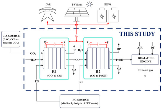
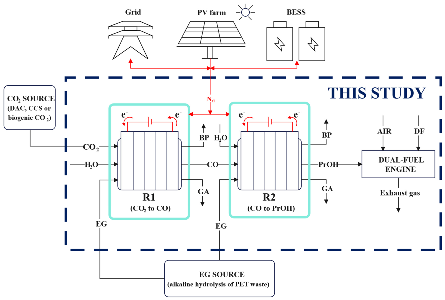
Figure 1 presents the schematic diagram of the integrated system analyzed in this study. The system consists of a tandem electrochemical reactor and a dual-fuel engine. The main product of the process is n-propanol. After synthesis, n-propanol is supplied to the engine and co-combusted with diesel fuel (DF). Different energy shares of n-propanol and diesel fuel were investigated during engine operation.
Figure 1.
Schematic diagram of the integrated system analyzed in this study.
The tandem reactor consists of two electrochemical reactors connected in series. In the first reactor (R1), CO2 is electrochemically reduced to carbon monoxide. In the second reactor (R2), CO is converted into n-propanol. In both reactors, ethylene glycol is oxidized to glycolic acid at the anode. The analysis also considers side reactions leading to the formation of by-products (BPs).
This study focuses on a comprehensive parametric analysis of the tandem electrochemical reactor system. The analysis was performed for the optimal operating point of the dual-fuel engine determined from the experimental investigation. CO2 capture, ethylene glycol production, electricity generation from photovoltaic systems, and battery energy storage system (BESS) operation were outside the scope of this study. It was assumed that the CO2 supplied to the process originates from sources compliant with the requirements for renewable fuels of non-biological origin (RFNBO). These sources include direct air capture (DAC), biogenic sources, and, during the transition period, industrial point sources. It was also assumed that the ethylene glycol used in the anodic reactions is produced by the alkaline hydrolysis of PET waste. As in conventional water electrolysis systems, the electricity required for the electrochemical processes was assumed to be supplied from renewable energy sources.
2.1. Dual-Fuel Engine
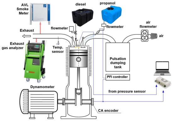
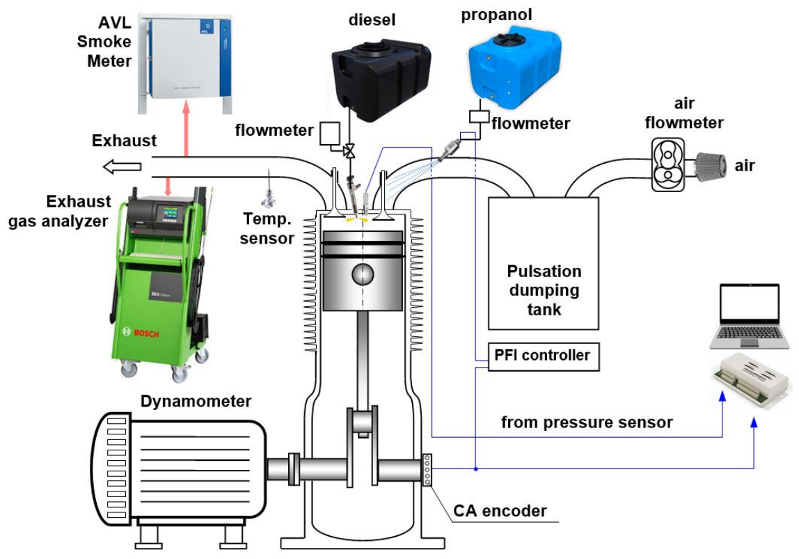
The experimental investigation was carried out using an industrial single-cylinder compression ignition engine, Andoria 1CA90 (Andoria Sp. z.o.o., Andrychów, Poland). The engine operated at a constant speed of 1500 rpm and under constant load. In all test cases, the engine load was kept constant, corresponding to an average indicated power of . It was equipped with the original direct diesel fuel injection system and an additional port fuel injection (PFI) system. Due to the relatively high latent heat of vaporization of n-propanol, fuel injection into the intake manifold may promote fuel film formation on the surfaces of the intake manifold and intake valves, particularly during cold start or transient operation. However, the experiments were conducted under steady-state conditions after the engine had reached thermal equilibrium. Under these conditions, the elevated temperature of the intake components and continuous airflow promoted fuel evaporation, thereby limiting the effect of wall wetting. Since the wall temperature and fuel film thickness were not measured directly, the formation of a thin fuel film cannot be completely excluded and should be considered in future studies. The PFI system supplied liquid fuel to the intake manifold at a pressure of 3 bar upstream of the intake valve. The injection control system synchronized fuel injection with the intake valve timing, enabling sequential fuel injection. The fuel temperature was maintained at a constant level by a specially designed fuel supply system that did not require a feed pump. The schematic diagram of the experimental test bench is shown in Figure 2, and the main engine specifications are listed in Table 1.
Figure 2.
Diagram of a dual-fuel engine laboratory stand.
Table 1.
Basic parameters of the tested engine.
The in-cylinder pressure was recorded using an engine indication system consisting of a Kistler 6061 SN 298131 piezoelectric pressure sensor (accuracy ±0.5%) (Kistler Instrumente AG, Winterthur, Switzerland), a Kistler 5011B charge amplifier (linearity FS < ±0.05%) (Kistler Instrumente AG, Winterthur, Switzerland), a crankshaft position encoder with a resolution of 1° crank angle (CA), a 16-bit Measurement Computing USB-1608HS (Measurement Computing Corporation, Norton, MA, USA) data acquisition module operating at a sampling frequency of 20 kHz, and a computer-based data acquisition and analysis system.
The air flow measurement system included a 150 dm3 surge tank, a TP-204K-1b-100-1.5 temperature sensor (CZAKI THERMO-PRODUCT, Raszyn, Poland) and a Common CGR-01 Roots flow meter (COMMON SA, Łódź, Poland). The exhaust gas composition was measured using a Bosch BEA 350 gas analyzer (Robert Bosch GmbH, Germany). The analyzer was used to measure THC, CO, CO2, NO, O2, and excess air ratio (λ).
Soot concentration was measured using an AVL Smoke Meter (AVL List GmbH, Graz, Austria) under the actual engine operating conditions. The measured values were not converted to standard temperature and pressure conditions and were not corrected to a normalized oxygen concentration in the exhaust gas. The temperature and pressure corresponded to the conditions at the exhaust gas sampling point. During the experiments, the exhaust gas temperature at the sampling point was approximately 210 °C, while the exhaust system overpressure was approximately 2.8 kPa.
In this study, the engine was operated in dual-fuel mode. n-Propanol was supplied to the intake manifold using the port fuel injection (PFI) system, while diesel fuel served as the ignition fuel. The dual-fuel configuration provides high flexibility in controlling the energy share of both fuels. It also allows the fuel ratio to be adjusted according to fuel availability and operating conditions.
n-Propanol was selected as the supplementary fuel because of its favorable physicochemical properties, including a relatively high heating value and the presence of oxygen in its molecular structure. Due to its low cetane number, n-propanol cannot be used as the sole fuel in compression ignition engines. However, it can be efficiently co-combusted with diesel fuel in a dual-fuel configuration. The main properties of the fuels used in this study are listed in Table 2. In all analyzed cases, the air mass flow rate supplied to the engine was kept constant at 25.22 kg/h. This value was obtained from experimental measurements and was used to determine the excess air ratio and, indirectly, the cylinder filling coefficient.
Table 2.
Fuel parameters [18,19,20].
Methodology for Determining Engine Operating Parameters
The engine operating parameters were determined from the recorded in-cylinder pressure traces. One of the main indicators used to characterize the performance of a reciprocating internal combustion engine is the indicated mean effective pressure (IMEP). For a single engine cycle, IMEP was calculated as follows:
where:
—instantaneous pressure in the engine cylinder;
—instantaneous cylinder volume;
—engine displacement volume;
—engine cycle number.
For a more comprehensive evaluation of engine performance, combustion stability is often analyzed in greater detail [21,22]. Due to the cyclic operation of a reciprocating engine and the cycle-to-cycle variations in combustion, the engine performance was evaluated using the mean value calculated from a series of measurements. In this study, the average was determined from 150 consecutive engine cycles:
The coefficient of variation in the indicated mean effective pressure () is defined as:
where:
—the standard deviation of IMEP;
—the average IMEP calculated from 150 consecutive engine cycles.
The indicated engine power () was calculated from the indicated mean effective pressure as:
where:
—the crankshaft rotational speed.
In the dual-fuel engine, chemical energy is supplied by both diesel fuel injected through the original direct injection system and n-propanol supplied to the intake manifold by the PFI system. The total chemical energy input to the engine was calculated as:
where:
—the diesel fuel mass flow rate;
—the n-propanol mass flow rate;
—the higher heating value of diesel fuel;
—the higher heating value of n-propanol.
Unlike conventional engine studies, all efficiencies reported in this work were calculated on a higher heating value (HHV) basis. This approach ensures consistency with the analysis of the tandem electrochemical reactor system and enables direct comparison of the efficiencies of individual energy conversion stages. It should be noted that the use of HHV results in lower numerical efficiency values compared with calculations based on the lower heating value (LHV). However, this difference does not affect the observed trends or the main conclusions of the study.
The indicated thermal efficiency (ITE) was calculated as the ratio of the indicated engine power to the total chemical energy input:
In single-fuel engines, fuel consumption is commonly expressed as the specific fuel consumption (SFC) in g/kWh. For dual-fuel engines operating on fuels with different heating values, the specific energy consumption (SEC) provides a more appropriate performance metric. The SEC was calculated as:
The energy share of n-propanol in the total chemical energy supplied to the engine () was calculated as:
All engine performance parameters presented in this study were calculated from the average values of three independent repetitions performed for each operating point.
2.2. Tandem Electrochemical Reactor System
Reference values of the main operating parameters were adopted to perform the parametric analysis of the tandem electrochemical reactor system. These parameters included the current density and the cell voltage of each reactor. The calculation assumptions are summarized in Table 3.
Table 3.
Calculation assumptions for the electrochemical reactors.
A reference current density of 200 mA/cm2 was selected because this value is widely recognized in the literature as the minimum threshold for the industrial implementation of electrochemical CO2 conversion systems [23,24,25]. Different cell voltages were assumed for the two reactors. Although the operating voltage ranges reported for CO2 electroreduction to CO and CO electroreduction to multicarbon products partially overlap, the production of C2+ products generally requires higher cell voltages [23,24,25]. Therefore, the cell voltage of the CO generation reactor R1 was set to 2.3 V, while the cell voltage of the n-propanol synthesis reactor R2 was assumed to be 2.6 V.
2.2.1. Electrochemical Reactions
The tandem electrochemical reactor system includes both the main reactions responsible for the formation of the desired products and the side reactions competing for the transferred electric charge. The processes considered include cathodic reactions associated with the electroreduction of CO2 and CO, as well as anodic reactions involving the oxidation of ethylene glycol.
Cathodic reactions
In reactor R1, the main cathodic reaction is the electrochemical reduction of CO2 to CO
The competing hydrogen evolution reaction (HER) was also considered:
In reactor R2, the main cathodic reaction is the electrochemical reduction of CO to n-propanol. The formation of n-propanol from CO involves C–C coupling between C1 species, leading to the formation of C3 products. Detailed mechanisms of this process are described in the literature [26].
The formation of acetic acid Equation (12), ethylene Equation (13), ethanol Equation (14), and hydrogen Equation (15) was also included as competing reactions:
Anodic reactions
In both reactors, the anodic reaction was assumed to be the electrochemical oxidation of ethylene glycol to glycolic acid:
Side reactions leading to the formation of formic acid Equation (17) and oxygen evolution (OER) Equation (18) were also considered:
To account for the competition between the individual reaction pathways, Faradaic efficiencies were defined for all reaction products. The Faradaic efficiency represents the fraction of the total electric charge used for the formation of a given product. The reference Faradaic efficiencies adopted in the model for the main and side products of the electrochemical reactions are summarized in Table 4.
Table 4.
Reference Faradaic efficiencies adopted for the products of the electrochemical reactions in the reactor R1 and reactor R2.
The reference Faradaic efficiencies adopted for the main cathodic and anodic reactions correspond to the target performance of the tandem electrochemical reactor system being developed within the Horizon Europe project PHOENIX (Photo-electro Integrated Next-Generation Energy Technologies). These values were used as the reference case in the present system analysis.
For reactor R1, a Faradaic efficiency of 90% was assumed for the electrochemical reduction of CO2 to CO. This value is consistent with the performance of advanced Ag–Zn catalyst systems reported in the literature [27,28].
For reactor R2, the adopted assumptions reflect the performance of copper-based catalysts used for CO electroreduction [14,15]. A Faradaic efficiency of 50% for n-propanol production was selected as the target value for the tandem electrochemical reactor system under development within the Horizon Europe PHOENIX project. Achieving such a high selectivity at high current densities, however, remains a major technological challenge.
For both reactors, the anodic Faradaic efficiency for the oxidation of ethylene glycol to glycolic acid was assumed to be 90%. This value is consistent with the performance of palladium-based catalysts modified with transition metals [29,30].
2.2.2. Methodology for Modeling the Tandem Electrochemical Reactor System
For both electrochemical reactors, the molar flow rate of the generated or consumed species () was calculated using Faraday’s law of electrolysis. According to this law, the molar flow rate of a species produced or consumed at an electrode is proportional to the electric charge transferred through the electrolyte:
where:
—the Faradaic efficiency of species ;
—the current density;
—the area of reactor ;
—the Faraday constant;
—the number of electrons involved in the electrochemical reaction.
By introducing the molar mass of species , Equation (19) can be expressed in terms of the mass flow rate:
Assuming a uniform current density distribution over the electrode surface, the total current is given by:
The electrical power consumed by the electrochemical cell () was calculated as the product of the cell voltage () and the total current:
The energy efficiency calculations considered only the chemical energy of the main energy products generated at the cathodes. The chemical energy of the supplied ethylene glycol and the energy content of the anodic products were not included. In both reactors, ethylene glycol is oxidized to glycolic acid at the anode. Although glycolic acid is a valuable chemical product, it is not used as an energy carrier in the analyzed system. Therefore, the adopted efficiency definition provides a conservative assessment of the energy performance of the tandem electrochemical reactor system because it does not account for the benefits associated with the simultaneous production of valuable chemicals.
The energy efficiency of the first electrochemical reactor R1 was defined as the ratio of the chemical energy rate of the produced carbon monoxide to the total electrical power demand of the reactor system:
where:
—the mass flow rate of the produced carbon monoxide;
—the additional power demand of auxiliary equipment, such as pumps, compressors, and fans.
To simplify the subsequent derivation, a relative energy loss coefficient was introduced. This coefficient represents the ratio of the power consumed by the auxiliary equipment to the electrical power supplied directly to the electrochemical cell:
By substituting the CO production rate calculated from Faraday’s law and the expression for the electrical power of the electrochemical cell into Equation (23), the energy efficiency of the first reactor can be expressed as:
To simplify the subsequent analysis, the electrochemical conversion efficiency of the first reactor was defined as:
The energy efficiency of the first reactor can therefore be written as:
Equation (27) shows that the energy efficiency of the first reactor is determined by the cell voltage, the Faradaic efficiency of the CO2-to-CO reduction process, and the relative energy demand of the auxiliary equipment:
The energy efficiency of the second electrochemical reactor R2 was defined as the ratio of the chemical energy of the produced n-propanol to the total energy supplied to the process. In addition to the electrical power consumed by reactor R2, the chemical energy of the CO stream supplied from the first reactor was also included:
where:
—the mass flow rate of the produced n-propanol.
As for reactor R1, the relative energy loss coefficient was defined as:
By substituting the n-propanol production rate calculated from Faraday’s law and the expression for the electrical power of the electrochemical cell into Equation (29), the energy efficiency of the second reactor can be expressed as:
To simplify the subsequent analysis, the parameter was introduced. This parameter represents the ratio of the chemical energy of the CO stream to the chemical energy of the produced n-propanol:
In addition, the parameter was defined as a function of the number of electrons involved in the electrochemical reaction, the Faraday constant, and the physicochemical properties of n-propanol:
Using the parameters and , the energy efficiency of the second reactor can be written as:
Assuming a constant value of , the energy efficiency of the second reactor is determined by the Faradaic efficiency of n-propanol synthesis, the cell voltage, and the relative energy demand of the auxiliary equipment:
The energy efficiency of the tandem electrochemical reactor system was defined as the ratio of the chemical energy of the produced n-propanol to the total power demand of both reactors:
where:
and
represent the total power demand of the first and second reactor, respectively.
Using the definitions of the efficiencies of reactors R1 and R2, the overall efficiency of the tandem electrochemical reactor system can be expressed as:
Assuming a constant value of the parameter , the overall efficiency of the tandem electrochemical reactor system is determined solely by the efficiencies of reactors R1 and R2:
3. Experimental Evaluation of Dual-Fuel Engine Performance
The experimental investigation was carried out using a stationary compression ignition engine adapted for dual-fuel operation. In all test cases, the engine load was kept constant, corresponding to an average indicated power of kW. After stabilizing the engine under diesel-only operation, a portion of the chemical energy supplied by diesel fuel was gradually replaced with n-propanol. The operating conditions and selected engine performance parameters are summarized in Table 5.
Table 5.
Operating conditions and selected performance parameters of a dual-fuel engine.
3.1. Energy Efficiency of the Dual-Fuel Engine
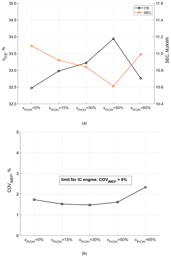
Increasing the energy share of n-propanol improved the energy efficiency of the analyzed dual-fuel engine. Figure 3a shows the effect of the n-propanol energy share on the indicated thermal efficiency (ITE) and the specific energy consumption (SEC). Within the range investigated, the indicated thermal efficiency increased from 32.47% under diesel-only operation to a maximum value of 33.94% at . At the same time, the specific energy consumption decreased from 11.09 to 10.61 MJ/kWh, indicating more efficient conversion of the fuel chemical energy. A further increase in the n-propanol energy share to 65% reduced the indicated thermal efficiency. This deterioration was associated with increased cycle-to-cycle variations in combustion, which are characteristic of high alcohol fuel fractions.
Figure 3.
Effect of the n-propanol energy share on combustion stability and engine performance: (a) indicated thermal efficiency (ITE) and specific energy consumption (SEC); (b) coefficient of variation in the indicated mean effective pressure ().
The effect of the n-propanol energy share on engine stability is presented in Figure 3b. Combustion stability was evaluated using the coefficient of variation in the indicated mean effective pressure (). A slight decrease in was observed as the n-propanol energy share increased to . A further increase in the alcohol fuel fraction reduced combustion stability. The lowest value of 1.47% was obtained at , whereas a value of 1.73% was recorded during diesel-only operation.
It should be noted that remained below 5% in all investigated cases. This value is commonly accepted as the limit for stable operation of compression ignition engines [31]. The results indicate that co-combustion of n-propanol with diesel fuel improves the energy efficiency of the engine while maintaining acceptable combustion stability. From the perspective of integration with the tandem electrochemical reactor system, the best compromise between energy efficiency and combustion stability was achieved at .
3.2. Emissions
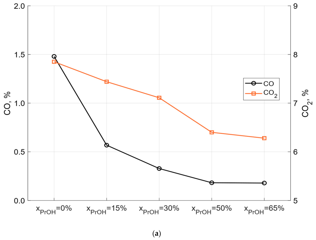
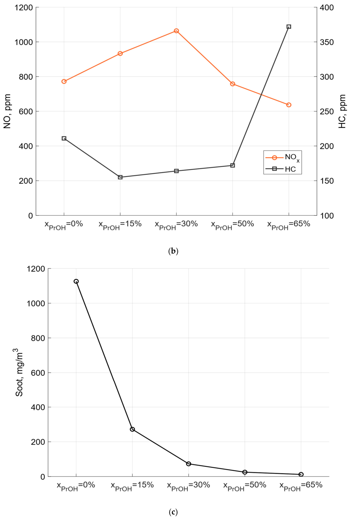
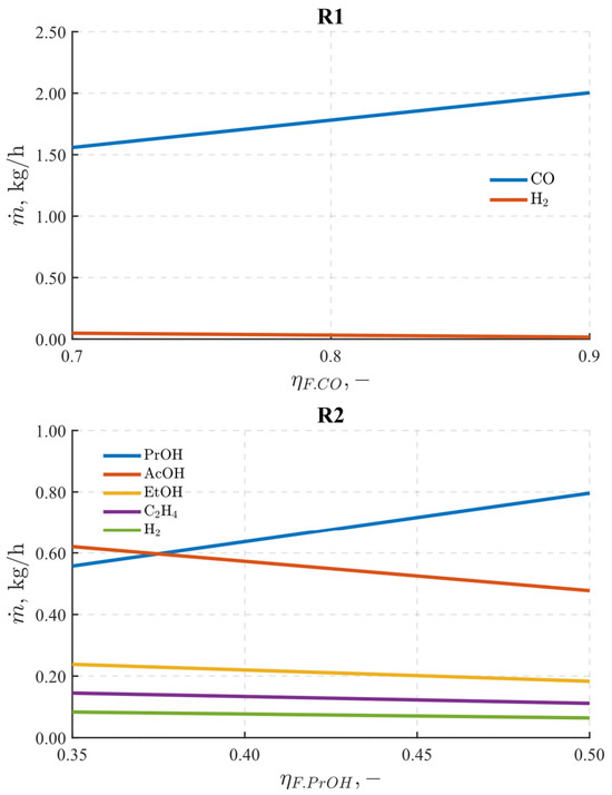
The performance of a reciprocating internal combustion engine cannot be evaluated solely based on its energy efficiency. Under increasingly stringent environmental regulations, the analysis of exhaust emissions is equally important. Engine exhaust gases contain combustion products determined by the combustion stoichiometry, such as CO2, H2O, and nitrogen, as well as harmful pollutants, including CO, HC, NO, and soot. The emissions of these compounds depend on several factors, among which the fuel type and combustion conditions are the most important. The exhaust emissions measured for different n-propanol energy shares are presented in Figure 4.
Figure 4.
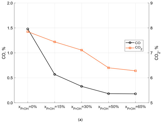
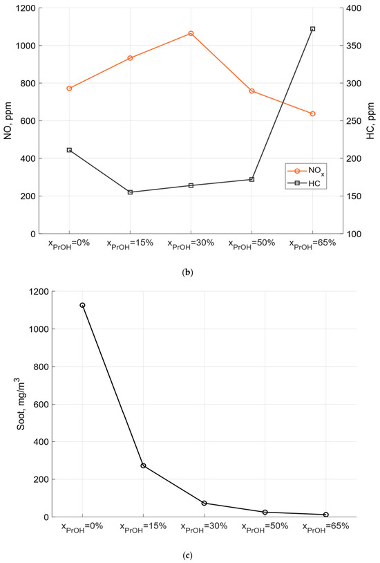
Effect of the n-propanol energy share on exhaust emissions: (a) CO and CO2 emissions; (b) NO and HC emissions; (c) soot emissions.
The n-propanol energy share had a significant effect on CO2 and CO emissions (Figure 4a). Replacing diesel fuel with n-propanol reduced the CO2 concentration in the exhaust gas. At , the CO2 concentration decreased from 7.85% to 6.28%, corresponding to a reduction of approximately 20% compared with diesel-only operation. An even larger effect was observed for CO emissions. At the highest n-propanol energy share, the CO concentration decreased by more than a factor of eight. Carbon monoxide is mainly formed under locally oxygen-deficient conditions, at low combustion temperatures, or when the oxidation of carbon to CO2 is incomplete. The oxygen contained in the n-propanol molecule promoted more complete combustion and reduced CO emissions.
The effect of the n-propanol energy share on NO and HC emissions is shown in Figure 4b. NO formation mainly depends on combustion temperature and the availability of oxygen and nitrogen. Since the engine operated under overall lean conditions, oxygen availability was not a limiting factor. Increasing the n-propanol energy share initially intensified the combustion process, resulting in higher peak cylinder pressure and temperature. Consequently, NO emissions increased. The maximum NO concentration of 1064 ppm was observed at intermediate n-propanol energy shares, representing an increase of more than 35% compared with diesel-only operation. A further increase in the n-propanol fraction reduced NO emissions. This behavior resulted from a delayed combustion process relative to top dead center (TDC) and a lower fresh charge temperature caused by the high latent heat of vaporization of n-propanol.
The trend observed for HC emissions was opposite to that of NO. Up to , the higher combustion temperature promoted more complete fuel oxidation, resulting in lower HC emissions than those measured during diesel-only operation. At , HC emissions increased again. This increase was associated with a longer ignition delay, lower combustion temperature, and greater cycle-to-cycle variations. The divergent trends of CO and HC observed at the highest n-propanol energy share may be related to the different mechanisms governing their formation and oxidation. The oxygen contained in n-propanol and improved mixture homogeneity may promote HC oxidation, whereas the cooling effect associated with its relatively high latent heat of vaporization may reduce the rate of CO oxidation to CO2.
Compression ignition engines are commonly associated with high soot emissions. The effect of the n-propanol energy share on soot emissions is presented in Figure 4c. As reported for many dual-fuel systems operating with alcohol fuels, increasing the n-propanol fraction significantly reduced particulate emissions. At , the soot concentration decreased from 1126 mg/m3 to 272 mg/m3, corresponding to a reduction by more than a factor of four compared with diesel-only operation. This reduction resulted from both the oxygen contained in the n-propanol molecule and the lower diesel fuel fraction, which reduced the formation of locally fuel-rich regions that promote soot formation.
The obtained results demonstrate that co-combustion of n-propanol with diesel fuel improves the energy efficiency of the engine while reducing the emissions of most investigated pollutants. Considering both the energy performance and the emission characteristics, the operating point with an n-propanol energy share of 50% was selected as the optimum case. This operating point was used as the reference condition for the subsequent analysis of the tandem electrochemical reactor system.
4. Performance Characteristics of the Tandem Electrochemical Reactor System
The analysis of the tandem electrochemical reactor system began with the evaluation of its performance under the reference operating conditions. The calculations were based on the required n-propanol production rate corresponding to the engine operating point of , which was equal to 0.796 kg/h. At this operating point, the dual-fuel engine achieved the highest indicated thermal efficiency together with favorable emission characteristics. Owing to the cascade configuration of the system, the operating conditions of reactor R2 determine the CO flow rate required from reactor R1. Consequently, the Faradaic efficiencies of the main and side reactions in reactor R2 directly affect the CO demand and, therefore, the operating conditions of the first reactor stage.
Table 6 and Table 7 summarize the selected operating parameters of both reactors calculated using the reference assumptions listed in Table 3 and Table 4. Under these conditions, reactor R1 produced 2.003 kg/h of CO with an energy efficiency of 47.77%, whereas reactor R2 produced 0.796 kg/h of n-propanol with an energy efficiency of 23.07%. The lower efficiency of reactor R2 results primarily from the chemical energy of the CO feed supplied to the reactor and the higher electrical energy demand of the n-propanol synthesis process.
Table 6.
Reference operating parameters for reactor R1.
Table 7.
Reference operating parameters for reactor R2.
Under the adopted operating conditions, n-propanol production was accompanied by the formation of significant amounts of by-products, particularly acetic acid (0.477 kg/h), ethanol (0.183 kg/h), and ethylene (0.111 kg/h). In contrast, hydrogen evolution in reactor R1 was negligible, and the H2 production rate did not exceed 0.016 kg/h. The anodic oxidation of ethylene glycol simultaneously produced glycolic acid together with small amounts of formic acid and oxygen. The total electrical power demand of the tandem reactor system was 31.95 kW, while the total reactors area was 6.39 m2.
In the next stage of the study, the effect of the Faradaic efficiency of the main reactions on the performance of reactors R1 and R2 was investigated. Due to the cascade configuration of the system, changes in the Faradaic efficiency affect not only the production rate of the main product but also the amount of by-products. The analysis was performed using fixed reactor areas corresponding to the reference operating conditions ( and ). The Faradaic efficiency of the main reaction was varied while maintaining the total Faradaic efficiency equal to unity by proportionally adjusting the Faradaic efficiencies of the side reactions.
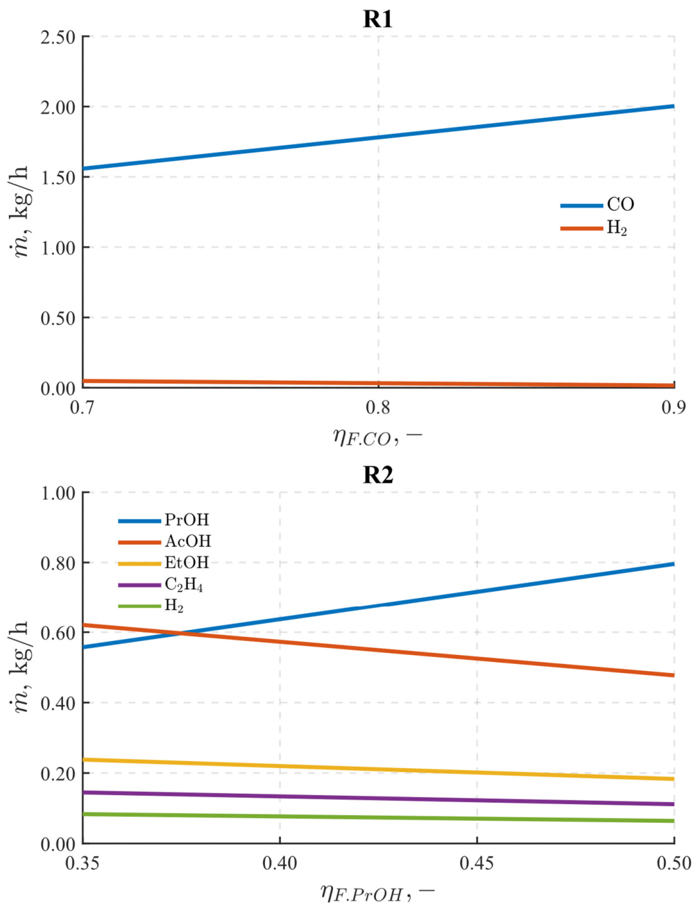
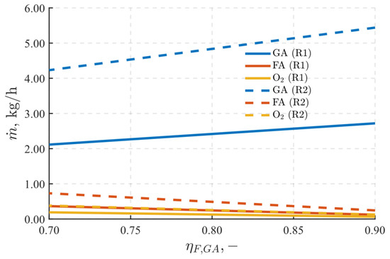
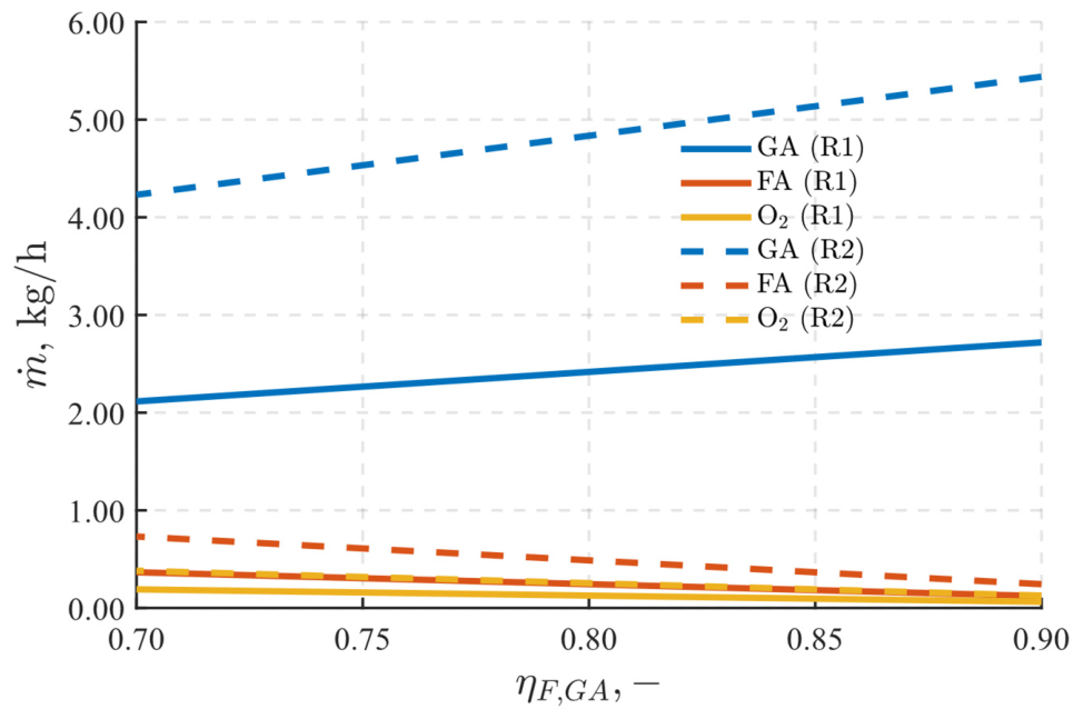
Figure 5 shows the effect of the Faradaic efficiency on the mass flow rates of the products generated in reactors R1 and R2. The mass flow rates of the anodic products are presented in Figure 6. For reactor R1, the Faradaic efficiency of the CO2-to-CO electroreduction reaction was varied from 0.70 to 0.90. This range corresponds to the performance reported for advanced catalysts used for CO2 electroreduction to CO [32,33,34]. For reactor R2, the Faradaic efficiency of n-propanol synthesis was varied from 0.35 to 0.50. The lower limit represents the values most commonly reported for the electrochemical conversion of CO to multicarbon products [11,35,36]. The reference Faradaic efficiency of 0.50 was selected according to the target performance of the tandem electrochemical reactor system being developed within the Horizon Europe PHOENIX project. However, achieving such a high selectivity at high current densities remains a major technological challenge and exceeds the performance of most currently available catalytic systems. For the anodic reaction, the Faradaic efficiency of ethylene glycol oxidation to glycolic acid was varied from 0.70 to 0.90 in both reactors [5,30].
Figure 5.
Effect of the Faradaic efficiency on the mass flow rates of the cathodic reaction products in reactors R1 and R2.
Figure 6.
Effect of the Faradaic efficiency on the mass flow rates of the anodic reaction products in reactors R1 and R2.
For reactor R1, the hydrogen production rate remained negligible compared with the CO production rate throughout the analyzed range. This result indicates that the CO2 electroreduction process is relatively insensitive to changes in the Faradaic efficiency of the main reaction within the range reported for advanced catalytic systems.
A different behavior was observed for the n-propanol synthesis reactor R2, where by-products accounted for a significant fraction of the total product stream. The analysis showed that decreasing the Faradaic efficiency of n-propanol synthesis substantially increased the production of acetic acid, which became one of the dominant products of the electrochemical process. At the lower limit of the analyzed Faradaic efficiency range, the amount of by-products became comparable to the n-propanol production rate. Under these conditions, additional separation and purification processes may be required for the cathodic products. This would increase the energy demand of the overall process because of the higher auxiliary power consumption.
Increasing the Faradaic efficiency of ethylene glycol oxidation increases the production rate of glycolic acid while reducing the formation of the side products, namely formic acid and oxygen. Owing to the more than twofold larger electrode area of reactor R2, the production rates of the anodic products are higher than those of reactor R1 over the entire range of the analyzed operating conditions.
4.1. Energy Efficiency of the Electrochemical Reactors
In the next stage of the study, the effects of the main operating parameters on the energy efficiency of the individual electrochemical reactors were investigated. The analysis began with the evaluation of the reactor energy efficiency over a wide range of operating conditions. The required n-propanol production rate corresponding to the engine operating point of (0.796 kg/h) was used as the design basis for all energy analyses.
The energy efficiency of reactor R1 depends on the Faradaic efficiency of the CO generation reaction, the cell voltage, and the auxiliary power consumption ratio. For reactor R2, the chemical energy of the CO feed supplied from reactor R1 must also be considered because CO serves as the reactant for n-propanol synthesis. If the parameter is assumed to be constant, the energy efficiency of reactor R2 depends only on the Faradaic efficiency, the cell voltage, and the auxiliary power consumption ratio. In the present analysis, however, was allowed to vary with the CO flow rate required for n-propanol synthesis as the Faradaic efficiency changed. This approach made it possible to evaluate the effect of the CO demand on the energy efficiency of reactor R2.
For reactor R1, the cell voltage was varied from 1.9 to 3.1 V. This range covers the values reported for laboratory-scale CO2-to-CO electroreduction systems and includes operating conditions relevant to future technological development [32,33,34]. For reactor R2, the cell voltage was varied from 2.4 to 3.4 V. Although this range partially overlaps with the voltages reported for CO2 electroreduction, the electrochemical synthesis of multicarbon products from CO generally requires higher operating voltages [11,33,37]. The selected voltage ranges therefore cover both the performance of current laboratory-scale systems and the expected directions of future technological development.
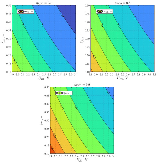
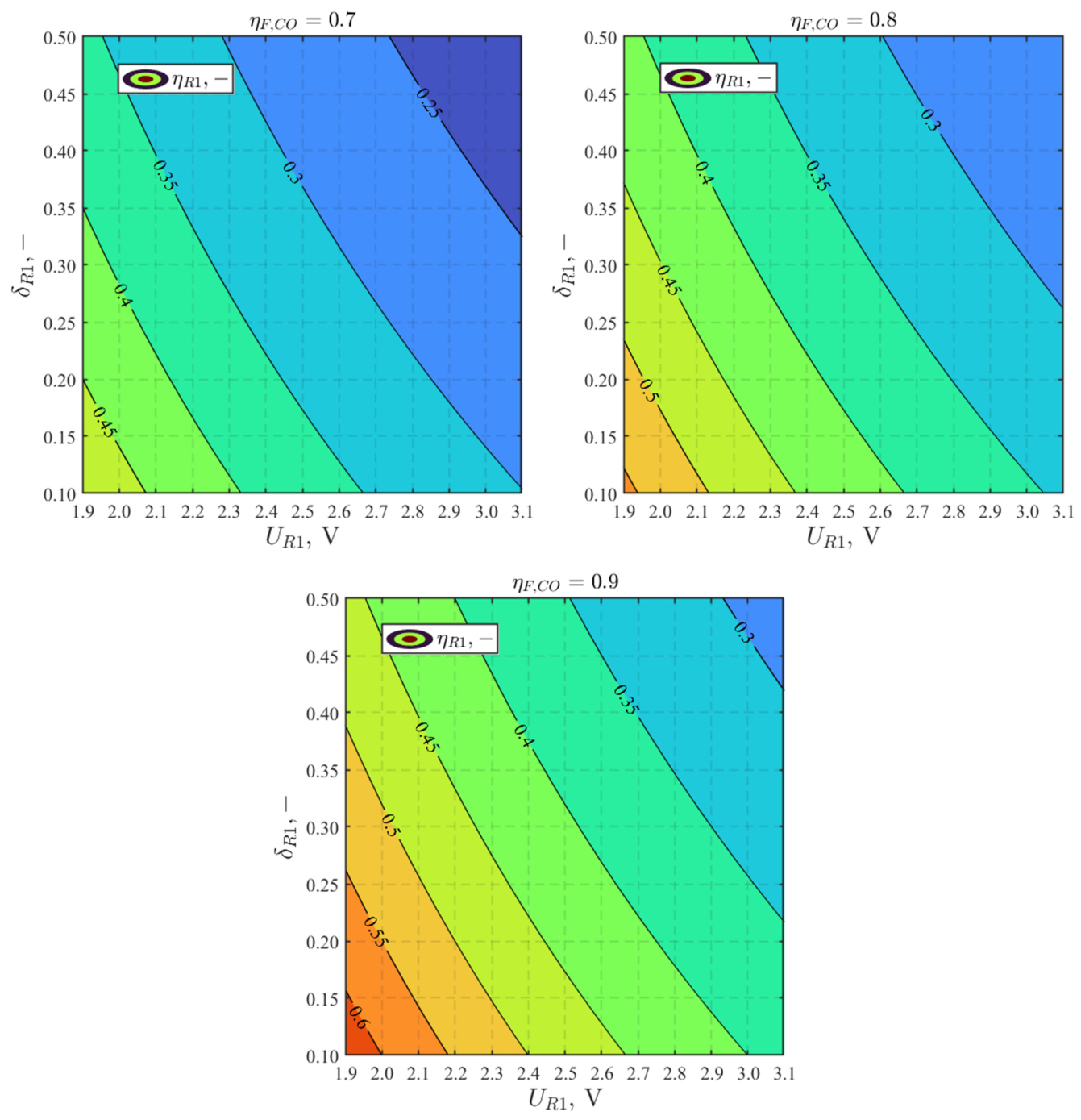
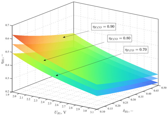
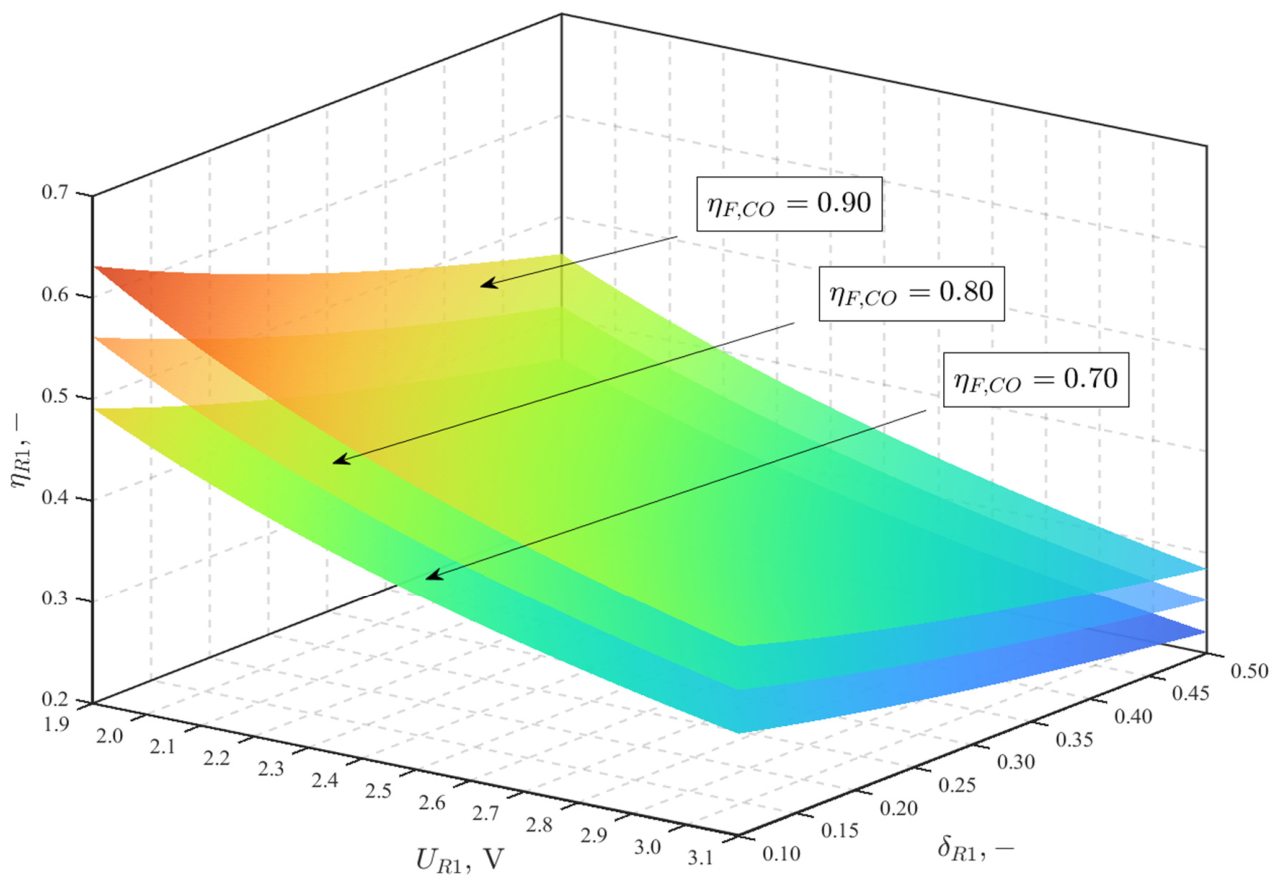
Figure 7 presents contour maps of the energy efficiency of reactor R1 as a function of the cell voltage () and the auxiliary power consumption ratio () for different values of the Faradaic efficiency of the CO2-to-CO electroreduction reaction. Figure 8 presents a three-dimensional visualization of the reactor energy efficiency over the analyzed operating range. In practical electrochemical systems, the cell voltage and the Faradaic efficiency are closely coupled through electrochemical reaction kinetics and mass transport phenomena. However, due to the rapid development of CO2 electrochemical conversion technologies and the continuous improvement in reactor performance, a broad parametric analysis was adopted instead of detailed kinetic modeling. Therefore, the relationships between cell voltage, auxiliary power consumption ratio, and Faradaic efficiency are presented as contour plots, allowing the identification of performance trends and optimal operating regions.
Figure 7.
Contour maps of the energy efficiency of reactor R1 () as a function of the cell voltage () and the auxiliary power consumption ratio () for different values of the Faradaic efficiency of the CO2-to-CO reaction (). The color scale represents the energy efficiency of reactor R1, with contour lines indicating the corresponding efficiency values.
Figure 8.
Three-dimensional visualization of the energy efficiency of reactor R1 as a function of the cell voltage (), the auxiliary power consumption ratio (), and the Faradaic efficiency of the CO2-to-CO reaction (). The individual surfaces correspond to the analyzed values of the Faradaic efficiency. The color scale represents the energy efficiency of reactor R1.
The analysis showed that increasing the cell voltage and the auxiliary power consumption ratio systematically reduced the energy efficiency of reactor R1. In contrast, increasing the Faradaic efficiency significantly improved the reactor performance by increasing the fraction of electrical energy stored as chemical energy in the main product. The results obtained for a Faradaic efficiency of , corresponding to the target performance of the PHOENIX project, are particularly important. Even at a moderate cell voltage of approximately 2.5 V, the reactor achieved an energy efficiency exceeding 40%. This result indicates that high process efficiency can be achieved without assuming unrealistically optimistic operating conditions. Although a lower Faradaic efficiency reduced the reactor energy efficiency, the system still maintained relatively high performance even at .
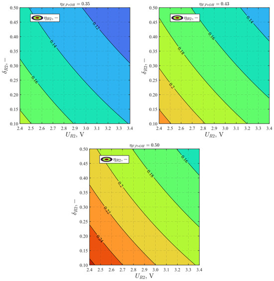
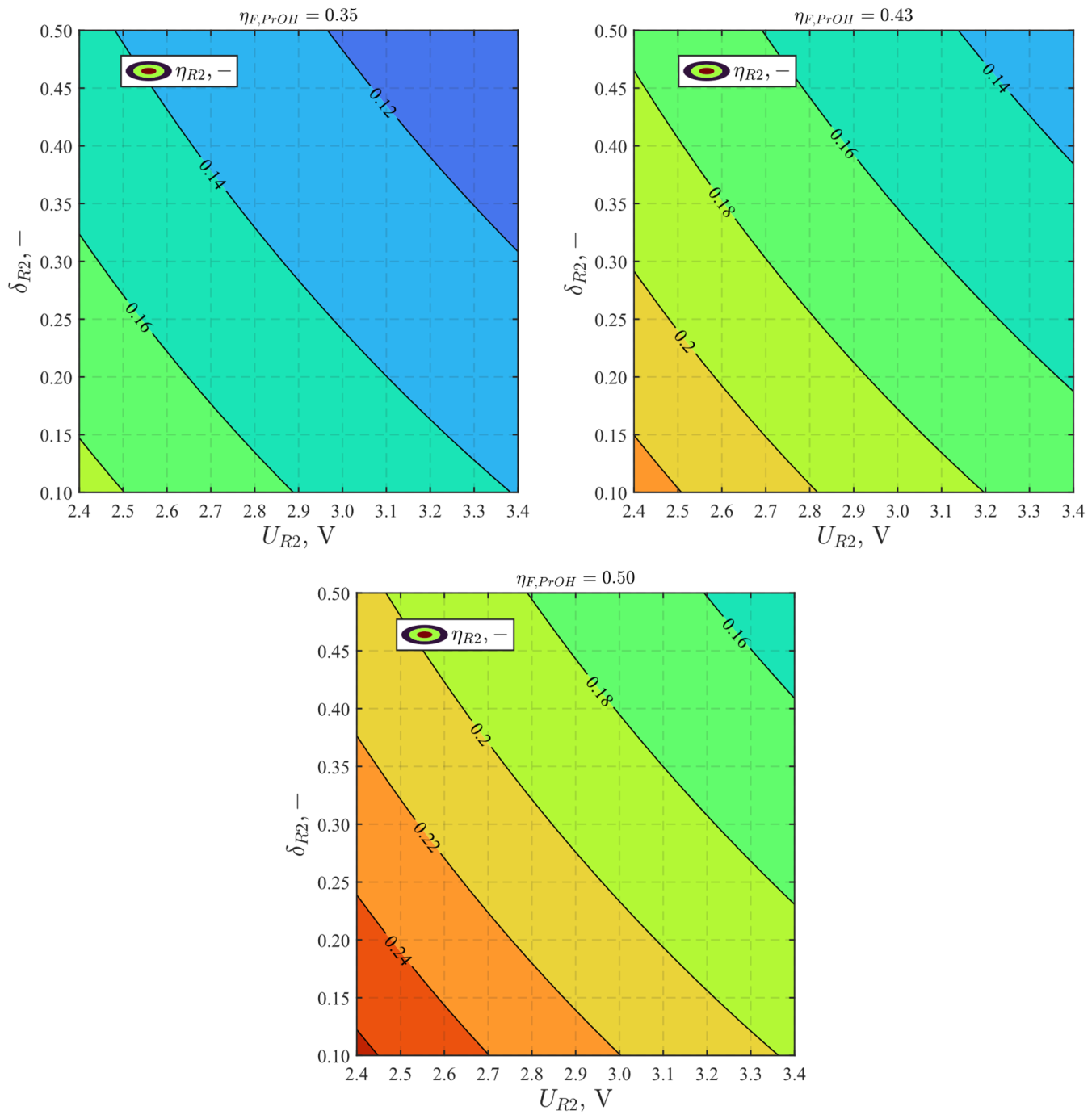
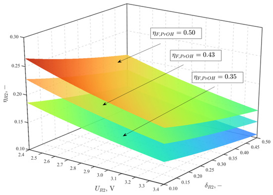
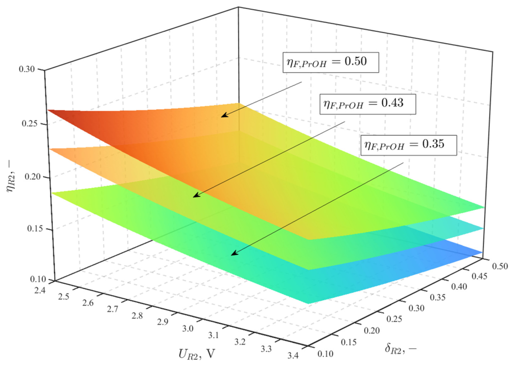
Figure 9 and Figure 10 present the corresponding energy efficiency characteristics of reactor R2. Compared with reactor R1, reactor R2 exhibits substantially lower energy efficiency, as indicated by the shift in the contour lines toward lower values. This behavior results from the additional energy input associated with the chemical energy of the CO feed supplied as the reactant for n-propanol synthesis, as well as from the presence of multiple competing side reactions.
Figure 9.
Contour maps of the energy efficiency of reactor R2 () as a function of the cell voltage () and the auxiliary power consumption ratio () for different values of the Faradaic efficiency of the CO-to-PrOH reaction . The color scale represents the energy efficiency of reactor R2, with contour lines indicating the corresponding efficiency values.
Figure 10.
Three-dimensional visualization of the energy efficiency of reactor R2 as a function of the cell voltage (), the auxiliary power consumption ratio (), and the Faradaic efficiency of the CO-to-PrOH reaction (). The individual surfaces correspond to the analyzed values of the Faradaic efficiency. The color scale represents the energy efficiency of reactor R2.
Reactor R2 is significantly more sensitive to changes in the Faradaic efficiency than reactor R1. Reducing from 0.50 to 0.35 shifts the entire range of energy efficiency characteristics toward lower values. At a Faradaic efficiency of , the reactor can achieve an energy efficiency exceeding 24%. However, the reactor efficiency decreases rapidly as the selectivity of the n-propanol synthesis reaction declines. In addition, the electrochemical synthesis of n-propanol from CO generally requires higher cell voltages than the CO2-to-CO electroreduction process, which further reduces the reactor energy efficiency.
Assuming the target Faradaic efficiency for n-propanol synthesis adopted in the PHOENIX project (), the energy efficiency of reactor R2 is expected to range from approximately 20% to 30%, depending on the operating conditions and the auxiliary power consumption ratio. It should be noted, however, that the actual energy demand of the system may be higher because of the complex composition of the cathodic products. The simultaneous formation of several gaseous and liquid products requires additional separation and purification processes, which increase the energy consumption of the auxiliary.
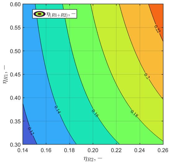
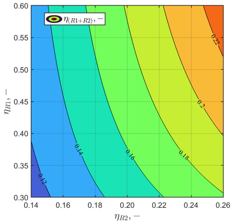
According to Equation (39), the overall energy efficiency of the tandem electrochemical reactor system was also analyzed as a function of the energy efficiencies of reactors R1 and R2. The results are presented in Figure 11. A constant value of parameter , corresponding to the reference operating conditions of the analyzed reactors, was assumed throughout the calculations. The ranges of the reactor energy efficiencies were selected based on the results presented in Figure 7 and Figure 9 for the target Faradaic efficiencies of the main products.
Figure 11.
Contour map of the energy efficiency of the tandem electrochemical reactor system () as a function of the energy efficiencies of reactors R1 and R2. The color scale represents the energy efficiency of the tandem electrochemical reactor system.
For the analyzed range of reactor efficiencies, the overall energy efficiency of the tandem electrochemical reactor system is expected to lie between 12% and 22%. Although these values are relatively low, it should be emphasized that the adopted efficiency definition considers only the chemical energy stored in the main product, namely n-propanol. The numerator of Equation (39) does not include the chemical energy of the other cathodic products or the value of the products generated at the anode. Likewise, the denominator does not include the chemical energy of the ethylene glycol supplied as the reactant for the anodic process.
4.2. Criterion for Improving Energy Efficiency
To determine the conditions leading to an increase in the energy efficiency of the analyzed reactors, a sensitivity analysis based on the total differential of the efficiency function was performed. This approach makes it possible to evaluate the effect of changes in the main operating parameters on the reactor energy efficiency and to identify the parameters responsible for improving or deteriorating the process performance.
For reactor R1, the energy efficiency can be expressed as a function of the Faradaic efficiency of the CO generation reaction, the cell voltage, and the auxiliary power consumption ratio, as given by Equation (28). Therefore, the total change in the reactor energy efficiency can be written as:
Substituting the expression for the energy efficiency of reactor R1 gives:
The condition for an increase in the reactor energy efficiency is:
which leads to:
An analogous analysis was performed for the n-propanol synthesis reactor. Unlike reactor R1, the energy efficiency of reactor R2 includes an additional term associated with the chemical energy of the CO stream supplied as the reactant for n-propanol synthesis. In the present analysis, this term was assumed to remain constant. Therefore, the reactor energy efficiency can be expressed as a function of the Faradaic efficiency, the cell voltage, and the auxiliary power consumption ratio:
After entering the auxiliary parameters:
and
the total differential of the reactor energy efficiency becomes:
Assuming that the reactor energy efficiency increases:
the following criterion is obtained:
The obtained criterion shows that the energy efficiency of the analyzed reactors can increase only when the relative increase in the Faradaic efficiency exceeds the combined effect of the relative increase in the cell voltage and the auxiliary power consumption ratio. Therefore, improving the selectivity of the electrochemical process does not automatically lead to higher energy efficiency. The benefits resulting from an increase in the Faradaic efficiency may be partially or completely offset by an increase in the cell operating voltage or in the energy demand of the auxiliary equipment. Consequently, the development of electrochemical conversion technologies should focus not only on maximizing the Faradaic efficiency but also on reducing the cell voltage and the energy consumption of the supporting infrastructure. This conclusion is valid for both reactor R1 and reactor R2. It should be emphasized, however, that the proposed criterion only indicates the direction of parameter changes required to improve the energy efficiency. It does not quantify the relative importance of the individual parameters. Therefore, an additional analysis based on normalized sensitivity coefficients was performed.
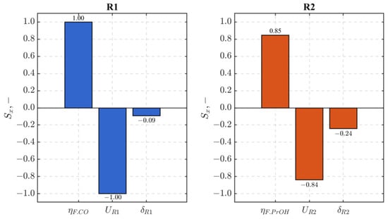
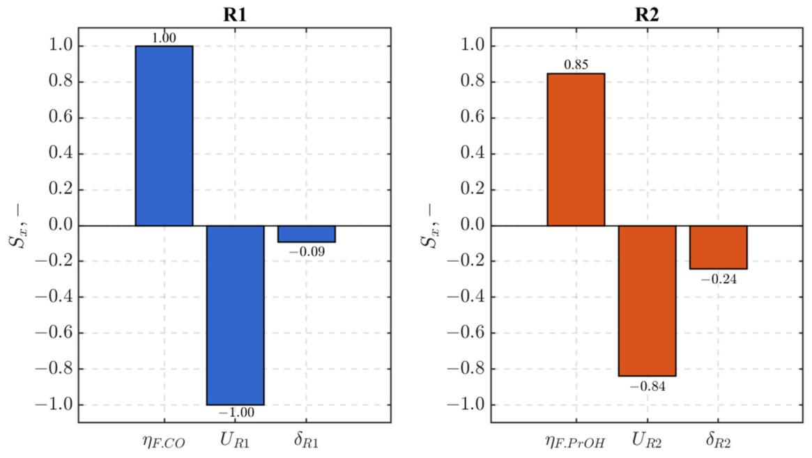
To quantitatively evaluate the influence of the individual operating parameters on reactor energy efficiency, normalized sensitivity coefficients were determined for the reference operating point used in the baseline analysis. These coefficients describe the relative change in energy efficiency resulting from a 1% relative change in a given parameter. They therefore enable a direct comparison of the effects of the Faradaic efficiency, the cell voltage, and the auxiliary power consumption ratio.
Because reactor R1 produces a relatively simple product mixture, the reference value of the auxiliary power consumption ratio was assumed to be . For reactor R2, a higher value of was adopted because the more complex mixture of gaseous and liquid products requires additional separation and purification processes. The normalized sensitivity coefficients were calculated according to:
where:
—the analyzed process parameter;
– the energy efficiency of the analyzed reactor.
The results presented in Figure 12 show that the energy efficiency of both reactors is most sensitive to changes in the Faradaic efficiency and the cell voltage. For reactor R1, the normalized sensitivity coefficients with respect to the Faradaic efficiency and the cell voltage are equal to 1 and −1, respectively. This indicates that both parameters have the same influence on the reactor energy efficiency in terms of absolute magnitude. A similar trend was observed for reactor R2, for which the corresponding sensitivity coefficients are 0.85 and −0.84. In both reactors, the influence of the auxiliary power consumption ratio is significantly smaller.
Figure 12.
Normalized sensitivity coefficients of the energy efficiency with respect to the Faradaic efficiency, cell voltage, and auxiliary power consumption ratio for reactors R1 and R2. The coefficients were determined for the reference operating point assuming a 1% relative change in the analyzed parameter.
These results indicate that the greatest potential for improving the energy efficiency of the analyzed reactors lies in increasing the Faradaic efficiency and reducing the cell voltage. In contrast, reducing the auxiliary power demand has a considerably smaller effect. Therefore, optimization efforts should primarily focus on parameters directly related to the electrochemical processes.
4.3. Required Reactors Area
To evaluate the practical implications of the selected operating conditions, the effects of current density and Faradaic efficiency on the required reactor area of reactors R1 and R2 were analyzed. The calculations were performed for the reference production rates of the main products, namely the CO production rate in reactor R1 and the n-propanol production rate in reactor R2 adopted in the baseline analysis. The reactor area is one of the key design parameters because it directly affects the electrolyzer size, capital cost, and scalability of the technology.
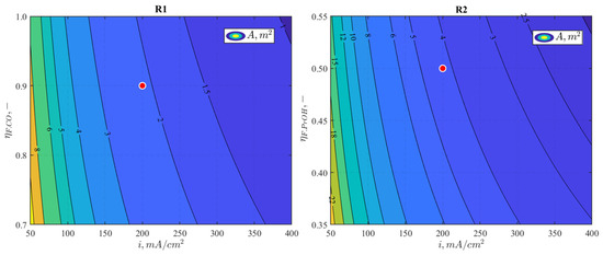
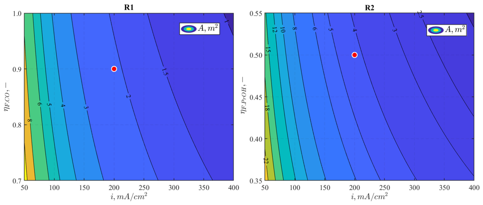
Figure 13 presents contour maps of the required reactor area as a function of the current density and the Faradaic efficiency for both reactors. The marked points indicate the reference operating conditions corresponding to a current density of 200 mA/cm2, adopted as the minimum value for industrial applications, and the target Faradaic efficiencies assumed for both electrochemical processes.
Figure 13.
Contour maps of the required reactor area () as a function of the current density () and the Faradaic efficiency () for reactors R1 and R2. The color scale represents the required reactor area, with contour lines indicating the corresponding area values. The marked points indicate the reference operating conditions corresponding to the minimum industrial current density of 200 mA/cm2 and the target Faradaic efficiencies adopted in the PHOENIX project.
For both reactors, increasing the current density and the Faradaic efficiency reduced the required reactor area. However, the contour plots show that the current density has a much stronger influence on the reactor area than the Faradaic efficiency. The calculated reactor areas are relatively small, indicating that the proposed reactor system is feasible from a practical engineering perspective. An increase in the required reactor area would, however, lead to higher capital expenditure, which may affect the production cost of n-propanol and, consequently, its market competitiveness. This is particularly important when considering the use of n-propanol as a fuel in dual-fuel engines, as its production cost should be competitive with the current market price of this fuel.
5. Perspective
Therefore, further development of this technology requires an economic assessment of the entire fuel production chain [38]. Electrochemical synthesis of n-propanol has the potential to reduce production costs. However, its economic competitiveness should be evaluated using techno-economic analysis (TEA) and life cycle assessment (LCA). In addition, future experimental studies of the dual-fuel engine could be extended to other energy carriers produced by the tandem electrochemical reactor system, particularly H2 and ethanol.
The calculated energy efficiency of the tandem reactor system should be regarded as a conservative estimate. The analysis considered only the chemical energy stored in the main energy products and did not account for the potential benefits associated with the simultaneous production of valuable co-products. In addition, the complex product distribution in reactor R2 requires separation and purification processes. The energy demand and economic implications of these downstream processes should be investigated in future studies to determine their impact on the overall performance and viability of the system.
Future system-level analyses should consider the entire technology chain. This includes CO2 capture, alkaline hydrolysis of PET waste, ethylene glycol production, and the supply of renewable electricity to the electrochemical reactors. Such an approach will enable a comprehensive assessment of the proposed technology for renewable fuel production and its contribution to a circular economy.
The Faradaic efficiencies and reaction pathways assumed in the model require further experimental validation. Future experimental studies should also identify and characterize the products formed during the two-step electroreduction of CO2 to n-propanol.
6. Conclusions
The experimental results confirmed that n-propanol is a promising fuel for dual-fuel compression ignition engines. Increasing the n-propanol energy share resulted in a systematic reduction in CO and CO2 emissions, although the highest energy share was accompanied by increased HC emissions. Considering both the emission characteristics and the engine energy efficiency, the optimum operating point was obtained at . At this condition, the indicated thermal efficiency reached 33.94%, which was higher than that achieved during diesel-only operation. These results demonstrate the potential of n-propanol to improve both the environmental performance and energy efficiency of dual-fuel engines.
The experimentally determined optimum engine operating point was used to define the required n-propanol production rate and to parameterize the tandem electrochemical reactor model. The results showed that the operating conditions of the n-propanol synthesis reactor R2 determine the requirements of the overall system, including the required CO production rate in reactor R1. Reactor R1 exhibited high selectivity for CO production, whereas reactor R2 produced significant amounts of by-products, particularly acetic acid. These results indicate that increasing the selectivity of the n-propanol synthesis process is essential for further improvement of the overall system performance.
The parametric analysis showed that the energy efficiency of both reactors is mainly determined by the Faradaic efficiency and the cell voltage. The proposed optimization criterion demonstrated that an increase in energy efficiency requires the improvement resulting from higher Faradaic efficiency to exceed the adverse effects of increased cell voltage and auxiliary power consumption. The sensitivity analysis confirmed that Faradaic efficiency and cell voltage have a substantially greater influence on reactor energy efficiency than auxiliary power consumption.
The overall energy efficiency of the tandem electrochemical reactor system ranged from 12% to 22%. Compared with some other Power-to-Fuel pathways, such as e-methanol and e-diesel production, for which energy efficiencies exceeding 50% have been reported, this efficiency is relatively low [39]. However, the adopted efficiency definition considered only the chemical energy stored in n-propanol and did not account for the value of the other reaction products. In addition, the complex product distribution, particularly in reactor R2, requires separation and purification, which may impose an additional energy penalty. On the other hand, the economic value of the co-produced chemicals may partially offset the additional energy consumption and separation costs. Therefore, a comprehensive assessment of the proposed technology should consider both the energy requirements of product separation and the economic value of co-produced chemicals.
Achieving the target Faradaic efficiencies assumed in this study remains a key challenge for further development of the proposed technology. This requires advanced electrochemical catalysts, particularly for n-propanol synthesis in reactor R2, to simultaneously improve Faradaic efficiency and selectivity while reducing cell voltage.
Author Contributions
Conceptualization, J.K. and K.N.; methodology, J.K., K.N. and W.T.; software, K.N.; validation, J.K., K.N. and W.T.; formal analysis, K.N. and W.T.; investigation, J.K., K.N. and W.T.; resources, W.T. and J.K.; data curation, K.N. and W.T.; writing—original draft preparation, K.N. and W.T.; writing—review and editing, J.K., K.N. and W.T.; visualization, K.N. and W.T.; supervision, J.K.; project administration, J.K.; funding acquisition, J.K. All authors have read and agreed to the published version of the manuscript.
Funding
The PHOENIX project received funding from the European Union’s Horizon Europe research and innovation program under grant agreement No. 101172764. Views and opinions expressed are however those of the author(s) only and do not necessarily reflect those of the European Union. Neither the European Union nor the granting authority can be held responsible for them.
Data Availability Statement
The original contributions presented in this study are included in the article. Further inquiries can be directed to the corresponding author.
Conflicts of Interest
The authors declare no conflicts of interest.
References
- Davis, S.J.; Lewis, N.S.; Shaner, M.; Aggarwal, S.; Arent, D.; Azevedo, I.L.; Benson, S.M.; Bradley, T.; Brouwer, J.; Chiang, Y.M.; et al. Net-Zero Emissions Energy Systems. Science 2018, 360, eaas9793. [Google Scholar] [CrossRef] [Scilit] [PubMed]
- Hulak, D.; Remiorz, L. Methane Production via Direct CO2 Electrolysis: A Modelling Study. Int. J. Hydrogen Energy 2026, 241, 155209. [Google Scholar] [CrossRef] [Scilit]
- Ding, X.; Zhang, J.; Li, Y. CO Electroreduction: What Can We Learn from Its Parent Reaction, CO2 Electroreduction? eScience 2023, 3, 100137. [Google Scholar] [CrossRef] [Scilit]
- Kotowicz, J.; Hulak, D.; Remiorz, L.; Brzęczek, M.; Böhm, Ł.; Baszczeńska, O.; Janusz-Szymańska, K.; Niesporek, K. Improving the Performance of Photoelectrochemical CO Reduction through Ethylene Glycol Oxidation. J. Power Sources 2026, 678, 240075. [Google Scholar] [CrossRef] [Scilit]
- Deng, K.; Lian, Z.; Wang, W.; Yu, J.; Yu, H.; Wang, Z.; Xu, Y.; Wang, L.; Wang, H. Lattice Strain and Charge Redistribution of Pt Cluster/Ir Metallene Heterostructure for Ethylene Glycol to Glycolic Acid Conversion Coupled with Hydrogen Production. Small 2024, 20, 2305000. [Google Scholar] [CrossRef] [Scilit] [PubMed]
- Liu, K.; Wang, Y.; Liu, F.; Liu, C.; Shi, R.; Chen, Y. Selective Electrocatalytic Reforming of PET-Derived Ethylene Glycol to Formate with a Faraday Efficiency of 93.2% at Industrial-Level Current Densities. Chem. Eng. J. 2023, 473, 145292. [Google Scholar] [CrossRef] [Scilit]
- Qian, Y.; Guo, J.; Zhang, Y.; Tao, W.; Lu, X. Combustion and Emission Behavior of N-Propanol as Partially Alternative Fuel in a Direct Injection Spark Ignition Engine. Appl. Therm. Eng. 2018, 144, 126–136. [Google Scholar] [CrossRef] [Scilit]
- Zhao, W.; Yan, J.; Gao, S.; Lee, T.H.; Li, X. The Combustion and Emission Characteristics of a Common-Rail Diesel Engine Fueled with Diesel, Propanol, and Pentanol Blends under Low Intake Pressures. Fuel 2022, 307, 121692. [Google Scholar] [CrossRef] [Scilit]
- Liu, G.; Ruan, C.; Li, Z.; Huang, G.; Zhou, Q.; Qian, Y.; Lu, X. Investigation of Engine Performance for Alcohol/Kerosene Blends as in Spark-Ignition Aviation Piston Engine. Appl. Energy 2020, 268, 114959. [Google Scholar] [CrossRef] [Scilit]
- Gawale, G.R.; Naga Srinivasulu, G. Experimental Investigation of Propanol Dual Fuel HCCI Engine Performance: Optimization of Propanol Mass Flow Rate, Impact of Butanol Blends (B10/B20/B30) as Fuel Substitute for Diesel. Fuel 2020, 279, 118535. [Google Scholar] [CrossRef] [Scilit]
- Wang, X.; Ou, P.; Ozden, A.; Hung, S.F.; Tam, J.; Gabardo, C.M.; Howe, J.Y.; Sisler, J.; Bertens, K.; García de Arquer, F.P.; et al. Efficient Electrosynthesis of N-Propanol from Carbon Monoxide Using a Ag–Ru–Cu Catalyst. Nat. Energy 2022, 7, 170–176. [Google Scholar] [CrossRef] [Scilit]
- Propanol Price-Historical & Current | Intratec.Us. Available online: https://www.intratec.us/solutions/primary-commodity-prices/commodity/propanol-prices? (accessed on 24 June 2026).
- Bushuyev, O.S.; De Luna, P.; Dinh, C.T.; Tao, L.; Saur, G.; van de Lagemaat, J.; Kelley, S.O.; Sargent, E.H. What Should We Make with CO2 and How Can We Make It? Joule 2018, 2, 825–832. [Google Scholar] [CrossRef] [Scilit]
- Bhoyar, T.; Kim, D.; Aftabuzzaman; Kim, J.Y.; Lee, K. Electrocatalytic CO2/CO Reduction to Propanol: A Critical Review. Mater. Futur. 2025, 4, 042102. [Google Scholar] [CrossRef] [Scilit]
- Xue, Y.; Lv, X.; Yang, C.; Song, L.; Zhang, L.; Zheng, G. Promoting Electrocatalytic CO2 Reduction to N-Propanol over Ethanol at Cu Step Sites. Chem. Sci. 2025, 16, 13944–13950. [Google Scholar] [CrossRef] [Scilit] [PubMed]
- Zhou, L.; Huang, Z.; Guan, C.; Zhang, Y.; Bai, S.; Kuang, M.; Yang, J. Synergistic Electroconversion of CO2-to-n-Propanol Over Atomically Dispersed Lewis Acid Zr-Doped Cuδ+ Catalysts. Adv. Funct. Mater. 2024, 35, 2418727. [Google Scholar] [CrossRef] [Scilit]
- Chen, C.; Wang, M.; Zhang, Y.; Yang, X.; Zou, K.; Lin, W.; He, M.; Wu, H.; Han, B. Efficient CO2 Electroreduction to N-Propanol on a Matching Cobalt Phthalocyanine/Copper Tandem Catalyst. Green Chem. 2025, 27, 5449–5454. [Google Scholar] [CrossRef] [Scilit]
- Redel-Macías, M.D.; Leiva-Candia, D.E.; Soriano, J.A.; Herreros, J.M.; Cubero-Atienza, A.J.; Pinzi, S. Influence of Short Carbon-Chain Alcohol (Ethanol and 1-Propanol)/Diesel Fuel Blends over Diesel Engine Emissions. Energies 2021, 14, 1309. [Google Scholar] [CrossRef] [Scilit]
- Yusri, I.M.; Mamat, R.; Najafi, G.; Razman, A.; Awad, O.I.; Azmi, W.H.; Ishak, W.F.W.; Shaiful, A.I.M. Alcohol Based Automotive Fuels from First Four Alcohol Family in Compression and Spark Ignition Engine: A Review on Engine Performance and Exhaust Emissions. Renew. Sustain. Energy Rev. 2017, 77, 169–181. [Google Scholar] [CrossRef] [Scilit]
- Jamrozik, A.; Tutak, W.; Grab-Rogaliński, K. Combustion Stability, Performance and Emission Characteristics of a CI Engine Fueled with Diesel/n-Butanol Blends. Energies 2021, 14, 2817. [Google Scholar] [CrossRef] [Scilit]
- Hosseini, S.E.; Wahid, M.A. Effect of Ammonia-Hydrogen Fuel Ratio on Combustion Stability, Performance and Emissions of an Industrial Diesel Engine. Int. J. Hydrogen Energy 2026, 205, 153373. [Google Scholar] [CrossRef] [Scilit]
- Tutak, W.; Jamrozik, A.; Grab-Rogalí, K.; Rakopoulos, D.; Rakopoulos, D.C.; Karpetis, A. The Effect of RME-1-Butanol Blends on Combustion, Performance and Emission of a Direct Injection Diesel Engine. Energies 2021, 14, 2941. [Google Scholar] [CrossRef] [Scilit]
- Gawel, A.; Jaster, T.; Siegmund, D.; Holzmann, J.; Lohmann, H.; Klemm, E.; Apfel, U.P. Electrochemical CO2 Reduction-The Macroscopic World of Electrode Design, Reactor Concepts & Economic Aspects. iScience 2022, 25, 104011. [Google Scholar] [CrossRef] [Scilit] [PubMed]
- Lin, J.; Yan, S.; Zhang, C.; Hu, Q.; Cheng, Z. Electroreduction of CO2 toward High Current Density. Processes 2022, 10, 826. [Google Scholar] [CrossRef] [Scilit]
- Hu, X.-M.; Liang, H.-Q.; Rosas-Hernández, A.; Daasbjerg, K. Electrochemical Valorization of Captured CO2: Recent Advances and Future Perspectives. Chem. Soc. Rev. 2025, 54, 1216–1250. [Google Scholar] [CrossRef] [Scilit] [PubMed]
- Ruqia, B.; Tomboc, G.M.; Kwon, T.; Kundu, J.; Kim, J.Y.; Lee, K.; Choi, S. Il Recent Advances in the Electrochemical CO Reduction Reaction towards Highly Selective Formation of Cx Products (X = 1–3). Chem. Catal. 2022, 2, 1961–1988. [Google Scholar] [CrossRef] [Scilit]
- Lu, Q.; Rosen, J.; Zhou, Y.; Hutchings, G.S.; Kimmel, Y.C.; Chen, J.G.; Jiao, F. A Selective and Efficient Electrocatalyst for Carbon Dioxide Reduction. Nat. Commun. 2014, 5, 3242. [Google Scholar] [CrossRef] [Scilit] [PubMed]
- Lamaison, S.; Wakerley, D.; Blanchard, J.; Montero, D.; Rousse, G.; Mercier, D.; Marcus, P.; Taverna, D.; Giaume, D.; Mougel, V.; et al. High-Current-Density CO2-to-CO Electroreduction on Ag-Alloyed Zn Dendrites at Elevated Pressure. Joule 2020, 4, 395–406. [Google Scholar] [CrossRef] [Scilit]
- Si, D.; Xiong, B.; Chen, L.; Shi, J. Highly Selective and Efficient Electrocatalytic Synthesis of Glycolic Acid in Coupling with Hydrogen Evolution. Chem. Catal. 2021, 1, 941–955. [Google Scholar] [CrossRef] [Scilit]
- Liu, F.; Gao, X.; Shi, R.; Guo, Z.; Tse, E.C.M.; Chen, Y. Concerted and Selective Electrooxidation of Polyethylene-Terephthalate-Derived Alcohol to Glycolic Acid at an Industry-Level Current Density over a Pd−Ni(OH)2 Catalyst. Angew. Chem. Int. Ed. 2023, 62, e202300094. [Google Scholar] [CrossRef] [Scilit] [PubMed]
- Heywood, J. Internal Combustion Engine Fundamentals; Tata Mcgraw Hill Education: Noida, India, 2018. [Google Scholar]
- Kauffman, D.R.; Thakkar, J.; Siva, R.; Matranga, C.; Ohodnicki, P.R.; Zeng, C.; Jin, R. Efficient Electrochemical CO2 Conversion Powered by Renewable Energy. ACS Appl. Mater. Interfaces 2015, 7, 15626–15632. [Google Scholar] [CrossRef] [Scilit] [PubMed]
- Lee, J.; Lee, W.; Ryu, K.H.; Park, J.; Lee, H.; Lee, J.H.; Park, K.T. Catholyte-Free Electroreduction of CO2 for Sustainable Production of CO: Concept, Process Development, Techno-Economic Analysis, and CO2 Reduction Assessment. Green Chem. 2021, 23, 2397–2410. [Google Scholar] [CrossRef] [Scilit]
- Zhou, L.Q.; Ling, C.; Zhou, H.; Wang, X.; Liao, J.; Reddy, G.K.; Deng, L.; Peck, T.C.; Zhang, R.; Whittingham, M.S.; et al. A High-Performance Oxygen Evolution Catalyst in Neutral-PH for Sunlight-Driven CO2 Reduction. Nat. Commun. 2019, 10, 4081. [Google Scholar] [CrossRef] [Scilit] [PubMed]
- Qiu, R.; Cui, L.; Peng, L.; Syzgantseva, O.A.; Li, J.; Fang, N.; Syzgantseva, M.A.; Jiang, Y.; Zhang, J.; Zhang, B.; et al. Cooperative Promotion of Electroreduction of CO to n-Propanol by *CO Enrichment and Proton Regulation. Chem. Sci. 2025, 16, 8897–8909. [Google Scholar] [CrossRef] [Scilit] [PubMed]
- Niu, W.; Chen, Z.; Guo, W.; Mao, W.; Liu, Y.; Guo, Y.; Chen, J.; Huang, R.; Kang, L.; Ma, Y.; et al. Pb-Rich Cu Grain Boundary Sites for Selective CO-to-n-Propanol Electroconversion. Nat. Commun. 2023, 14, 4882. [Google Scholar] [CrossRef] [Scilit] [PubMed]
- Monis Ayyub, M.; Kormányos, A.; Endr, B.; Janáky, C. Electrochemical Carbon Monoxide Reduction at High Current Density: Cell Configuration Matters. Chem. Eng. J. 2024, 490, 151698. [Google Scholar] [CrossRef] [Scilit]
- Baszczeńska, O.; Kotowicz, J.; Andretta, A.; Niesporek, K.; Brzęczek, M. Economic Analysis and Life Cycle Assessment of an Electrochemical Reactor for CO2 and Ethylene Glycol Conversion. Energies 2025, 18, 5125. [Google Scholar] [CrossRef] [Scilit]
- Colelli, L.; Dell’Aversano, S.; Bassano, C.; Vanga, G.; Gallucci, K.; Vilardi, G. Liquid E-Fuels for a Sustainable Future: A Comprehensive Review of Production, Regulation, and Technological Innovation. Energy Convers. Manag. 2026, 347, 120529. [Google Scholar] [CrossRef] [Scilit]

Disclaimer/Publisher’s Note: The statements, opinions and data contained in all publications are solely those of the individual author(s) and contributor(s) and not of MDPI and/or the editor(s). MDPI and/or the editor(s) disclaim responsibility for any injury to people or property resulting from any ideas, methods, instructions or products referred to in the content. |
© 2026 by the authors. Licensee MDPI, Basel, Switzerland. This article is an open access article distributed under the terms and conditions of the Creative Commons Attribution (CC BY) license.