


Abstract
DC-link voltage synchronization control (DVSC), or matching control, offers a simple grid-forming (GFM) solution for two-stage photovoltaic (PV) systems by linking the DC-link voltage to converter frequency. However, its low-frequency damping is sensitive to grid strength and power-transfer level. This paper investigates the damping and synchronization characteristics of DVSC-based grid-forming PV systems under varying operating conditions. A reduced-order small-signal model is developed to decompose the contributions of the DVSC loop, electrical network, and terminal-voltage regulation. The analysis reveals that the basic DVSC loop provides no inherent damping, while the interaction between voltage regulation, grid impedance, and transferred power may introduce negative damping or reduce the synchronizing margin. The operating-condition-dependent limitations of lead-phase correction and q-axis voltage feedforward are then identified. To supplement these methods, DC-link-voltage-feedback d- and q-axis voltage stabilizers are designed and integrated with DVSC reshaping in a composite stabilization scheme. Eigenvalue analysis and OPAL-RT real-time simulations demonstrate the complementary damping characteristics of the four stabilizing paths.
1. Introduction
The increasing penetration of photovoltaic (PV) generation is accelerating the transition toward converter-dominated power systems [1]. As the proportion of synchronous generation decreases, conventional grid-following converters, which rely on externally established grid voltage and phase references, may face synchronization and stability challenges in weak or low-inertia grids [2]. Grid-forming (GFM) control has therefore attracted increasing attention because it enables power electronic converters to establish local voltage and frequency references and to contribute to grid synchronization, voltage support, and frequency regulation [3,4,5,6]. These capabilities are particularly relevant to utility-scale PV plants whose grid-connection strength and operating power may vary significantly during normal operation.
Two-stage PV conversion systems, comprising a front-end DC/DC converter and a grid-connected DC/AC converter, provide additional flexibility for PV-side maximum power point tracking (MPPT), DC-link regulation, and AC-side grid support [7,8,9]. Existing GFM-PV implementations can be broadly categorized into power-synchronization-based control, DC-link-voltage-based synchronization, and nonlinear oscillator-based control. In power-synchronization-based schemes, the DC/AC converter establishes the AC voltage and frequency through active-power control, while the front-end converter or an auxiliary energy-storage device is generally required to regulate the DC-link voltage and maintain an active-power reserve [10,11,12,13,14,15]. Although these approaches can provide flexible grid-support functions, their implementation may require modified MPPT, reserved PV power, or additional DC-side energy storage.
Virtual oscillator control (VOC) enables decentralized synchronization by embedding nonlinear oscillator dynamics into the converter voltage generation process without relying on phase-locked loops [16,17]. Among various VOC approaches, dispatchable virtual oscillator control (dVOC) extends this concept by incorporating active and reactive power references into the nonlinear voltage-control law, providing programmable droop characteristics and decentralized grid-forming capability [18]. Previous studies have demonstrated its synchronization performance and nonlinear stability properties under different grid conditions [16,17].
DC-link voltage synchronization control (DVSC), also referred to as matching control, provides an alternative GFM solution by directly linking the DC-link voltage deviation to the converter frequency [19,20,21]. Unlike dVOC, which achieves synchronization through nonlinear oscillator dynamics with inherent nonlinear damping, DVSC derives its frequency response from the DC-link energy balance, providing a direct energy-based inertia mechanism analogous to the swing dynamics of synchronous machines. However, the basic DVSC loop does not introduce inherent damping, making its low-frequency stability sensitive to the interactions among DC-link dynamics, grid impedance, terminal-voltage regulation, and operating power [21,22,23,24].
Several synchronization-loop-oriented damping approaches have been investigated to improve the low-frequency stability of DVSC and related GFM converters. These approaches include synchronization-loop reshaping, lead-phase correction (LPC), active power-frequency feedforward (PFF), or voltage-frequency feedforward control (VqFF) [21,22,23,24,25]. These methods modify the gain and phase characteristics of the synchronization path and can improve damping around the designed operating point. Nevertheless, their effectiveness is generally sensitive to controller parameters, grid strength, and transferred power. A controller tuned for one operating condition may therefore provide limited damping when the grid or power level changes significantly [26,27].
In addition to synchronization-loop reshaping, the voltage-reference and voltage-regulation channels provide further degrees of freedom for damping enhancement. Since variations in the d- and q-axis voltage references affect the terminal-voltage magnitude, phase, output current, and active-power transfer, supplementary voltage-reference modulation can be used to shape the converter’s low-frequency power response. Relevant approaches include direct DC-bus control, voltage–power coupling, DC-link-effect-oriented controller design, and GFM control with explicit DC-voltage constraints or protection [25,28,29]. However, the d- and q-axis channels do not provide identical effects. Their damping and synchronizing contributions vary with the operating angle, grid impedance, transferred power, and voltage-loop dynamics. Consequently, a voltage-reference stabilizer that is effective in one operating region may become less effective or even reduce the synchronizing margin in another.
Although recent studies have addressed DC-link dynamics, grid-strength adaptability, synchronization stability, and voltage-oriented damping in GFM-PV systems [25,26,27,28,29], several issues remain insufficiently clarified. First, the contributions of the DVSC loop, electrical network, and terminal-voltage regulation are often analyzed separately, making their damping and synchronizing effects difficult to compare within a unified framework. Second, the operating-condition-dependent roles of d- and q-axis voltage-reference stabilization have not been fully distinguished from those of synchronization-loop reshaping. Third, it remains unclear whether these complementary control paths can be coordinated within a common fixed-gain structure to improve damping over a wider range of grid strengths and power-transfer levels.
To address these issues, this paper develops a reduced-order small-signal model for a two-stage DVSC-based GFM-PV system and separates the low-frequency contributions of the DVSC loop, electrical network, and terminal-voltage regulation. Based on this model, the effects of lead-phase correction, q-axis voltage feedforward, and DC-link-voltage-feedback d- and q-axis voltage stabilizers are analyzed under varying grid strengths and power levels. A composite stabilizer is then constructed by combining synchronization-loop reshaping with d/q-axis voltage-reference compensation. The main contributions of this paper are outlined as follows:
- A reduced-order small-signal model is developed to decompose the damping and synchronizing contributions of the DVSC loop, electrical network, and terminal-voltage regulation in two-stage GFM-PV systems.
- The operating-condition-dependent damping characteristics of LPC, VqFF, and DC-link-voltage-feedback d- and q-axis voltage stabilizers are analyzed within a unified framework, with particular attention to grid-strength and power-transfer variations.
- A composite stabilization strategy is proposed by coordinating synchronization-loop reshaping and d/q-axis voltage stabilizers, and the parameters are designed according to their effects on damping enhancement and synchronization margin.
- The effectiveness and robustness of the proposed control strategy are verified through eigenvalue analysis, time-domain simulations, and OPAL-RT real-time experiments under different grid strengths and operating conditions.
The paper is organized as follows. Section 2 presents the fundamental control of GFM-PV systems. Section 3 develops the reduced-order small-signal model and analyzes the synchronization and damping characteristics. Section 4 presents the design and implementation of the proposed composite stabilizer. Section 5 provides eigenvalue analysis and time-domain simulation results. Section 6 concludes the paper.
Notation
In the context, we use boldface letters to denote complex space vectors and italic letters to denote scalar variables and real transfer functions. In addition, is the nominal system frequency, is the unit value of a voltage vector’s magnitude, and is the voltage magnitude of the utility grid.
2. Description of GFM-PV Systems
2.1. Main Circuit
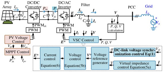
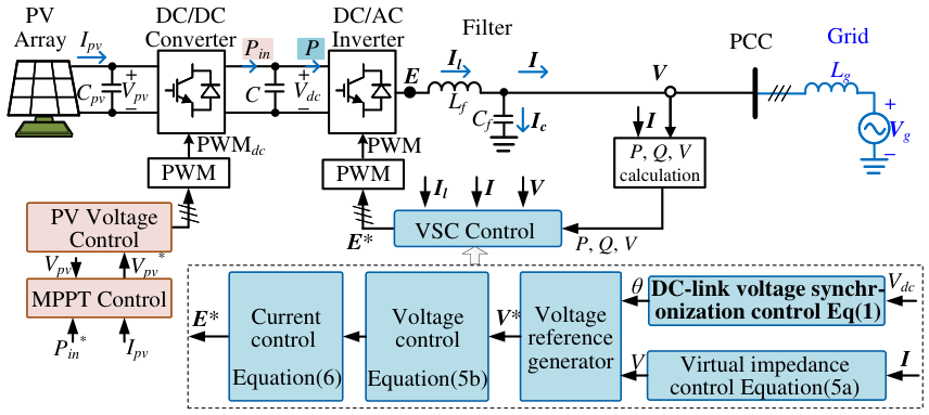
Figure 1 shows the configuration of a two-stage PV system [8]. It consists of a PV array, a DC/DC boost converter, a DC-link capacitor, a DC/AC grid-connected inverter, and an output filter (including an DC/DC converter regulates the PV-side voltage and performs maximum power point tracking (MPPT). From the perspective of the DC/AC inverter, the PV generation stage can thus be represented as an input power source . The DC/AC inverter is responsible for DC-link voltage regulation, grid synchronization, and AC-side voltage formation. The inverter output voltage vector is denoted by , and the filter capacitor voltage vector at the point of common coupling (PCC) is denoted by . The filter inductor current, filter capacitor current, and grid-injected current are represented by , , and , respectively. The grid is modeled by an equivalent voltage source connected through a grid inductance .
Figure 1.
Circuit diagram of a PV plant (Note that the superscript ∗ indicates the reference signal in the context)-Adapted from reference [30] with permission.
Since this paper focuses on the synchronization and damping behavior of the grid-connected inverter, the following analysis mainly considers the DC/AC inverter control and its interaction with the AC grid. The DC/DC converter dynamics are represented by the input power , while the inverter-side control determines the low-frequency stability characteristics of the GFM-PV system.
2.2. Main Control
The DC/AC inverter adopts a cascaded control structure composed of outer synchronization and voltage-reference generation loops, followed by inner voltage and current control loops. The outer loop implements DVSC (a controller) to establish the relationship between the DC-link voltage deviation and the converter angular frequency. With a proportional DVSC gain (where the controller in Figure 2a), the frequency and phase angle are given by [22]
where is the DC-link voltage, and is its reference. The generated phase angle defines the local reference frame used for voltage and current regulation. The proportional relationship in (1) defines the frequency-power synchronization characteristic. The steady-state operating point is determined by the power balance between the DC source and AC grid, rather than by proportional action alone.
Figure 2.
The outer loops: (a) DVSC; (b) AC voltage reference generator.
The transformation between the local frame (rotating with the angular speed ) and the synchronous frame (rotating at constant angular speed ) is expressed as
where and denote the complex vector in the frame and the frame, respectively. Unless otherwise specified, all variables are expressed in per-unit values.
The AC voltage reference is generated in the local frame. For the basic GFM control, the d-axis voltage reference is set to the nominal voltage magnitude, while the q-axis voltage reference is set to zero:
in Figure 2b. The corresponding voltage reference vector is
To improve the voltage-source behavior and shape the output impedance, a virtual impedance is introduced in the voltage control loop. The modified voltage reference and the filter inductor current reference are given by
where and are the virtual resistance and virtual inductance, and . The inner current loop regulates the filter inductor current to track . The inverter voltage command is expressed as
where . is the feedforward filter. and are PI controls, with the parameters (, ) and (, ). The system parameters are tabulated in Table 1. All controller parameters and constants are expressed in the per-unit (pu) system and are normalized based on the rated voltage and rated power of the PV system.
Table 1.
Converter System Parameters (On base of PV system)-Adapted from reference [30] with permission.
According to Kirchhoff’s circuit law (see Figure 1), the relationship between the currents and can be written as
where . The vector and are related by
These circuit and control equations form the basis for the small-signal synchronization and damping analysis developed in the next section.
3. Assessment of Damping and Synchronization Characteristics
This section develops a reduced-order small-signal model in the synchronous reference frame to examine the low-frequency stability of the DVSC-based GFM-PV system. The model separates the contributions of the DVSC loop, the electrical network, and the terminal-voltage controller, thereby clarifying how grid strength and power-transfer level affect the damping and synchronizing characteristics.
3.1. Reduced-Order Small-Signal Model
The analysis focuses on low-frequency synchronization dynamics. Since the inner current loop has a significantly larger bandwidth than the DVSC and terminal-voltage regulation loops, its dynamics are neglected. We thus assume in what follows. Meanwhile, the terminal-voltage magnitude and phase are determined by the outer control loops. Therefore, the terminal voltage can be expressed as in the synchronous reference frame.
Because the filter capacitor exchanges only reactive power, the active power transferred to the grid can be written as
where the subscript “⋆” denotes the conjugation operation.
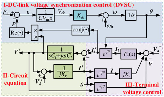
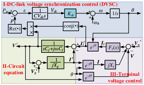
Figure 3 presents the nonlinear analytical model, which consists of three interacting subsystems. Part I addresses synchronization control (DVSC), Part II covers circuit dynamics, and Part III focuses on terminal-voltage control. These subsystems are coupled through the reference-frame transformations and the active-power feedback path.
Figure 3.
Block diagram of the mathematical model of GFM-PV system.
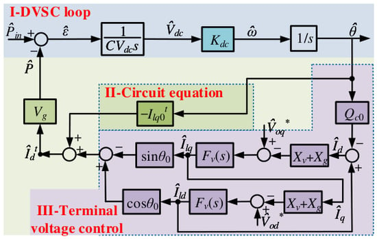
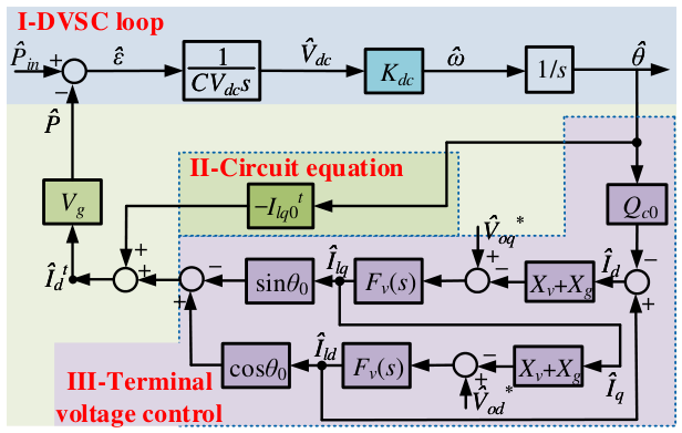
By linearizing the circuit and control equations around an operating point, the reduced-order model in Figure 4 is obtained. The corresponding derivation is provided in Appendix A. Notably, the filter capacitor dynamics are established in the synchronous reference frame; the perturbation of the synchronous-frame angular velocity is neglected because its influence is relatively small compared with the dominant capacitor current dynamics within the low-frequency range considered in this study. The resulting structure is analogous to the Heffron–Phillips (HP) model of a synchronous generator [31] and facilitates the separation of damping and synchronizing effects in the GFM-PV system.
Figure 4.
Reduced-order small-signal model of GFM-PV system.
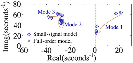
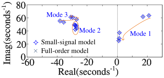
To verify the applicability of the proposed reduced-order model, the dominant low-frequency modes are compared with those of the full-order nonlinear model around a defined operating point. A single-machine infinite-bus system with pu is considered, and different grid-strength conditions are evaluated by varying . The comparison result in Figure 5 confirms that the proposed model preserves the dominant eigenvalue distribution and its variation trend under different grid conditions.
Figure 5.
Comparison of dominant low-frequency eigenvalues between the full-order model and the proposed small-signal model.
3.2. Damping and Synchronizing Contributions
The active-power response to a phase-angle perturbation is decomposed into components associated with the angle deviation and frequency deviation . The former represents a synchronizing contribution, whereas the latter represents a damping contribution. The effects of the three subsystems in Figure 4 are analyzed separately below.
3.2.1. Contribution of the DVSC Loop
The DVSC loop includes two integrators due to the and correlation. Its open-loop transfer function is
where . Equation (10) introduces a phase lag of approximately 180° and does not provide an inherent damping term. Therefore, the basic DVSC loop alone cannot actively damp low-frequency oscillations. The closed-loop damping must instead be supplied by the electrical network, terminal-voltage regulation, or additional stabilizing controllers.
3.2.2. Contribution of the Electrical Network
To isolate the contribution of the electrical network, the filter inductor current is treated as a prescribed quantity (i.e., ), and the terminal-voltage controller is temporarily excluded. The incremental active-power response to the phase-angle deviation is then
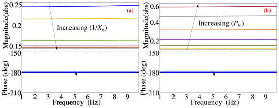
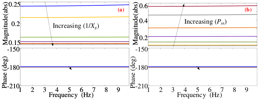
where ; () is a constant coefficient determined by the steady-state operating condition and system parameters. Under the considered generation operating conditions, is positive, and thus, . Consequently, the electrical-network contribution introduces a negative synchronizing component but no direct damping component.
Figure 6 shows the frequency response of for different grid impedances and input-power levels (based on (11)). The response remains predominantly angle dependent, while its magnitude changes with the operating condition. A larger negative synchronizing contribution reduces the overall synchronization margin and must be compensated by the voltage-forming control.
Figure 6.
Bode diagram of related to electrical-network contribution: (a) grid impedance changes at pu; (b) power level changes pu at .
3.2.3. Contribution of Terminal-Voltage Regulation
The terminal-voltage controller establishes the voltage-source behavior of the converter. Through the virtual impedance and voltage-feedback loops, a perturbation in the converter phase angle affects both the terminal voltage and the output current. The coordinate transformations further couple the voltage-control dynamics with the active-power response.
Based on the reduced-order model in Figure 4, the incremental active power associated with terminal-voltage regulation is
where . and are damping and synchronization coefficients. If , we have and .
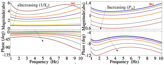
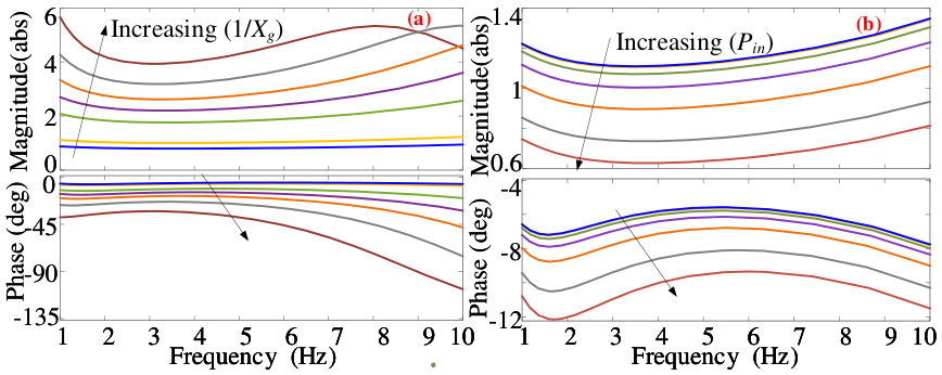
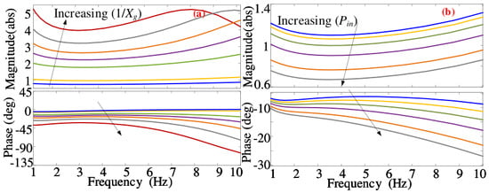
Equation (12) shows that terminal-voltage regulation can simultaneously provide a synchronizing contribution and introduce negative damping. Figure 7 presents the frequency response of under different grid-strength and power-transfer conditions. In the low-frequency range of interest, the phase response generally lies within 0°∼−90°. The component in phase with determines the synchronizing effect, whereas the quadrature component associated with determines the damping effect. The following observations can be made:
Figure 7.
Bode diagram of related to terminal-voltage regulation: (a) grid impedance changes at pu; (b) power level changes pu at .
- Significant negative damping arises with a large .
- can be quite small or even negative for very high .
- Negative damping deteriorates at lower power-transfer levels in weak grids, but is seldom affected by in strong grids.
3.3. Discussion on Instability Mechanism
The reduced-order model reveals that the three subsystems provide distinct and potentially conflicting contributions to the synchronization dynamics:
- The basic DVSC loop exhibits zero self-damping (), rendering system stability easily compromised.
- Electrical network introduces a negative synchronization factor () between and .
- Terminal-voltage regulation supports a positive synchronization factor (), but it may simultaneously introduce negative damping (). The negative damping serves more under strong grids and weak grids with low power level.
- In addition, at strong grids (with high ) or power-transfer levels (with high ), can become negative, posing a risk of synchronization destabilization.
The overall small-signal stability therefore depends on the balance among the synchronizing and damping contributions of these subsystems. In strong grids, the negative damping introduced through terminal-voltage regulation may dominate. In weak grids, the available damping and synchronizing margins become highly dependent on the operating power. Consequently, a controller tuned for one operating condition may not maintain adequate damping when the grid impedance or transferred power changes.
4. Implementation of the Composite Stabilizer
4.1. Control Rationale
As noted in Section 3, the basic DVSC loop enables self-synchronization of the GFM-PV system but provides no inherent damping. Moreover, the interactions among the DVSC loop, terminal-voltage regulation, grid impedance, and power-transfer level may introduce negative damping or weaken the synchronizing effect, thereby increasing the risk of low-frequency oscillations.
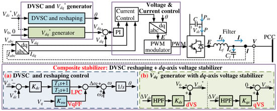
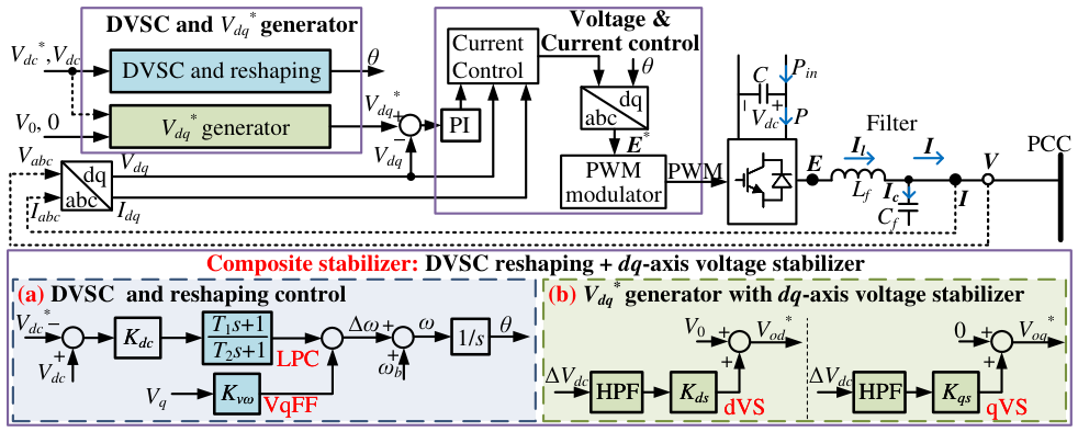
Existing DVSC reshaping methods, such as LPC [24] and VqFF [26,32], improve damping by modifying the synchronization loop, as shown in Figure 8a. However, their effectiveness is operating-point dependent and may deteriorate when the grid strength or transferred power varies significantly.
Figure 8.
Control structure of the DVSC-based GFM-PV system with the considered stabilizing paths.
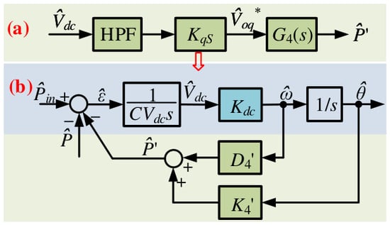
To supplement DVSC reshaping, this paper introduces d-axis and q-axis voltage stabilizers, denoted as dVS and qVS, respectively, as shown in Figure 8b. Both stabilizers use the dc-link voltage deviation () as the feedback signal and modify the corresponding terminal-voltage references. Since reflects the instantaneous active-power imbalance, appropriately designed voltage-reference compensation can generate supplementary active-power components that improve low-frequency damping.
The effectiveness of dVS and qVS depends on the coupling between the synchronization and terminal-voltage control loops, which varies with the grid impedance and operating power. Therefore, no individual stabilizing path is expected to provide sufficient damping over the entire operating range. This observation motivates a composite stabilization scheme that combines DVSC reshaping with the proposed -axis voltage stabilizers.
4.2. DVSC Reshaping for Damping Enhancement
4.2.1. Lead-Phase Correction
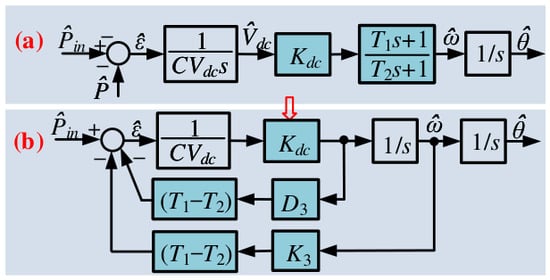
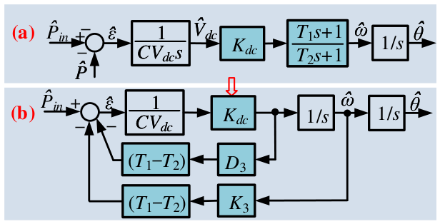
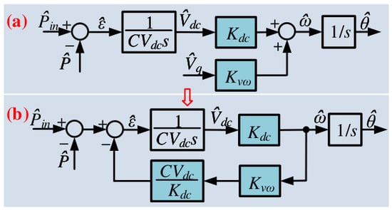
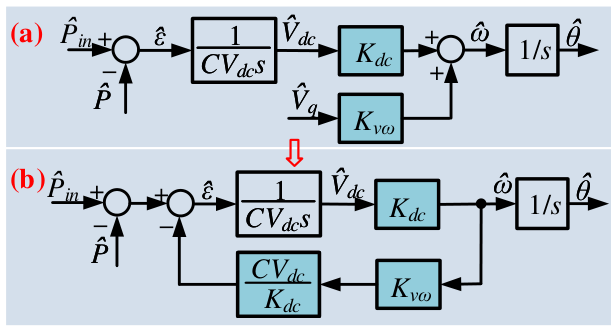
Figure 9a shows the linearized DVSC loop with LPC, and Figure 9b presents its equivalent reduced-order representation. Under the adopted approximation, the equivalent inertia and damping coefficients are
where and are the LPC time constants.
Figure 9.
LPC for droop: (a) LPC block; (b) the equivalent model.
- Fine-tuning offers an alternative way to improve damping . However, it also modifies the equivalent inertia () and transient response.
- should be held to ensure the inertia, damping, and fast-responding requirements.
Thus, LPC can enhance system response to grid perturbations but is restricted by parameter adjustments.
4.2.2. q-Axis Voltage Feedforward
In Figure 10a, VqFF is used to compensate for damping. It is known that
where . Mostly, for strong grids (since the output power angle of the PV inverter is usually small under normal grid-connected operating conditions, the small-angle approximation can be applied). Figure 10b can be used to present the contribution of VqFF. The equivalent damping can be obtained
where is the gain. However, in weak grids, is pronounced, and the impact of in (14) should not be underestimated. During a load power increment, decreases, potentially leading to reverse regulation of the system frequency.
Figure 10.
VqFF: (a) VqFF block; (b) the equivalent model.
- VqFF is effective for damping enhancement in strong grids but ineffective in weak grids.
Overall, LPC and VqFF can improve the damping of DVSC-based GFM-PV systems, but their performance is sensitive to controller parameters and operating conditions.
4.3. -Axis Voltage Stabilizer
4.3.1. Influence of Voltage-Reference Perturbations
The terminal-voltage references introduce additional degrees of freedom for regulating the active-power response. To evaluate their individual contributions, the phase-angle perturbation is temporarily neglected (), yielding the following power relationship:
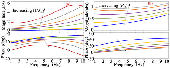
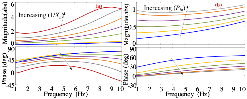
Figure 11 and Figure 12 depict the Bode diagram of and for different grid impedances and power-transfer levels. The resulting frequency-domain characteristics reveal several important properties:
Figure 11.
Bode diagram of (i.e., ): (a) at pu; (b) pu at .
Figure 12.
Bode diagram of (i.e., ): (a) at pu; (b) pu at .
- exhibits a phase lead of 0∼, tending toward 0 as or increases.
- The magnitude of rises with increasing or .
- shows a phase lag of 0∼, with increased lag as or increases.
- The magnitude of increases with but decreases as rises.
These characteristics indicate that the d- and q-axis voltage references can be modulated to generate supplementary active-power components. When appropriately coordinated with , these components can contribute to the damping and synchronizing characteristics of the GFM-PV system.
4.3.2. Implementation of -Axis Voltage Stabilizer
Based on the above transfer characteristics, two -axis voltage stabilizers are developed using the DC-link voltage perturbation as the feedback signal, as illustrated in Figure 13 and Figure 14. Each stabilizer includes a proportional control ( or ) and a high-pass filter (HPF) to block steady-state components.
Figure 13.
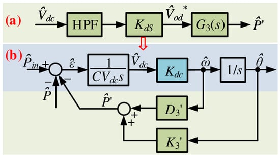
d-axis voltage stabilizer (dVS): (a) dVS; (b) the equivalent model.
Figure 14.
q-axis voltage stabilizer (qVS): (a) qVS; (b) the equivalent model.
In Figure 13a, the DC-link voltage is used to correct the d-axis voltage command. The compensated power is hence
The d-axis voltage stabilizer (dVS) can be equivalent to Figure 13b. Actually, a positive damping arises alongside a negative synchronization factor (based on Figure 11). The value of rises with an increase in or . For synchronization stability, should remain low to keep sufficiently small.
- dVS improves the damping ratio by increasing the damping contribution while reducing the synchronization factor (inspired by [31]).
- dVS may be less effective in weak grid and low power-transfer scenarios.
Unlike SGs, GFM-PV systems are able to provide damping effect through q-axis voltage regulation, as shown in Figure 14a. The compensated power is then obtained as
Figure 14b illustrates the effects of the q-axis voltage stabilizer (qVS), characterized by positive damping and synchronization (based on Figure 12). The value of increases with but decreases as rises.
- qVS can improve both damping and synchronization under weak-grid conditions.
- Its relative damping contribution decreases as the power-transfer level increases.
- Its effectiveness in strong grids may be moderate.
Under extremely weak-grid conditions (), qVS becomes particularly beneficial because both damping and synchronization margins are significantly reduced. In such scenarios, the system exhibits very low damping and synchronization coefficients. The effectiveness of DVSC reshaping and dVS is limited and may even introduce a negative synchronization factor. Thus, qVS is recommended for stabilizing weak grids by providing positive damping and synchronization contributions.
Table 2 summarizes the performances of LPC, VqFF, dVS, and qVS with respect to the damping enhancement, considering their design consideration and application deficiency. While LPC with fixed gains can provide damping, it lacks adaptability to changing grid conditions. In contrast, VqFF, dVS, and qVS effectively stabilize strong grids. dVS and qVS further enhance damping in weak grids, addressing instability challenges at extreme power levels. Therefore,
Table 2.
Comparison of the Considered Stability Paths.
- no single scheme can fulfill all stability requirements;
- however, these four damping methods are complementary, suggesting that combining them into a composite stabilizer could improve overall performance.
4.4. Composite Stabilizer for Varying Operating Conditions
The preceding analysis shows that the four stabilizing paths exhibit complementary characteristics:
- LPC reshapes the phase response of the DVSC loop but is sensitive to its fixed time constants and operating-point-dependent coefficients.
- VqFF provides effective damping under strong-grid conditions but may become less effective when the grid is weak.
- dVS provides a relatively strong damping contribution at high power-transfer levels but may reduce the synchronizing margin.
- qVS supplements both damping and synchronization under weak-grid and low-power conditions but provides less damping at high power levels.
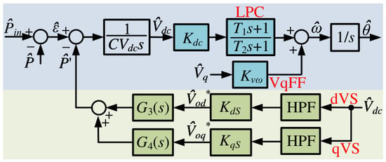
Table 2 summarizes the principal functions and limitations of the four stabilizing paths. No individual method provides uniformly strong damping over all grid-strength and power-transfer conditions. Therefore, the four paths are combined to form the composite stabilizer shown in Figure 15, and the parameter tuning procedure is given in Appendix B.
Figure 15.
Block diagram of the proposed composite stabilizer.
LPC and VqFF primarily reshape the synchronization loop, whereas dVS and qVS modify the terminal-voltage references. The resulting structure exploits the complementary characteristics of the synchronization and voltage-control paths. In particular, LPC and VqFF provide damping in strong-grid and moderate-power regions, dVS supplements damping as the transferred power increases, and qVS supports synchronization and damping in weak-grid and low-power conditions.
The proposed composite stabilizer does not require structural switching among the four paths. Instead, the stabilizing signals are applied simultaneously using fixed controller parameters. Its objective is therefore to improve damping over a wider set of operating conditions than can be covered by any individual stabilizing path. The eigenvalue and time-domain assessments in Section 5 evaluate this property under selected grid-strength and power-level variations.
5. Stability Assessment and Real-Time Validation
This section validates the stability analysis and evaluates the proposed composite stabilizer. Eigenvalue analysis and nonlinear time-domain simulations are first conducted on a single-PV infinite-bus system. OPAL-RT real-time simulations are then performed on a multi-bus system under varying grid strengths, power levels, and load disturbances.
5.1. Single-PV Infinite-Bus System
5.1.1. Effect of Grid Strength
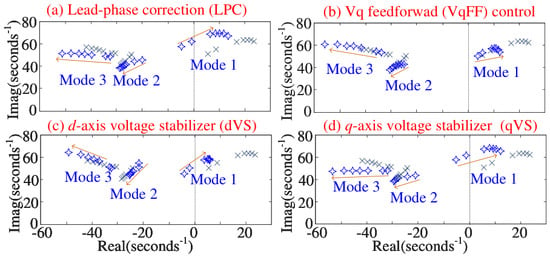
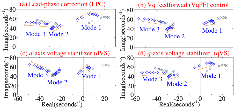
Figure 16 shows the trajectories of the three dominant low-frequency oscillatory modes as increases from to 28 at pu. Without supplementary stabilization, Mode 1 lies in the right-half plane and moves further to the right as the grid becomes stronger, whereas Modes 2 and 3 remain stable. This indicates that increasing grid strength does not necessarily improve the stability of the DVSC-based GFM-PV system.
Figure 16.
Pole trajectories of critical LFO modes when increases from to 28 ( pu, × represents the poles without any damping method). (a) With LPC (, ). (b) With VqFF (). (c) With dVS (). (d) With qVS ().
LPC, VqFF, dVS, and qVS all shift Mode 1 toward the left-half plane, but their effectiveness varies with the operating condition. LPC, dVS, and qVS provide sufficient damping at using the parameters in Table 1, whereas VqFF requires a substantially higher gain. Among the considered methods, dVS is relatively less sensitive to grid-strength variation.
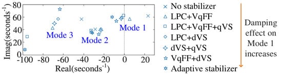
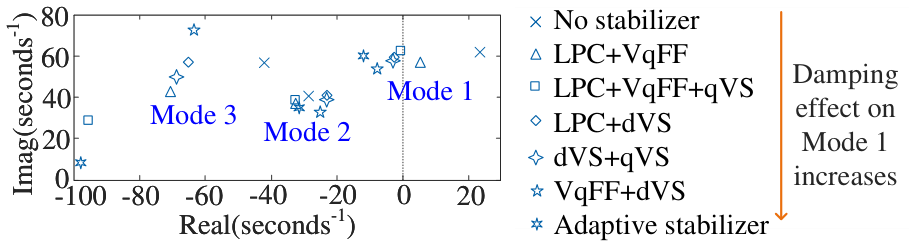
Figure 17 compares different stabilizer combinations under the strong-grid condition . The combination of LPC and VqFF cannot stabilize Mode 1, indicating that DVSC reshaping alone may provide insufficient damping in a very strong grid. Adding dVS substantially improves the dominant-mode damping. Among the tested combinations, the complete composite stabilizer produces the largest leftward displacement of Mode 1.
Figure 17.
Dominant-mode locations obtained using different combination of stabilizer strategies under the strong-grid case .
These results demonstrate that synchronization-loop reshaping and terminal-voltage stabilization provide complementary damping contributions.
5.1.2. Effect of Power-Transfer Level in a Weak Grid
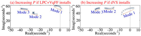
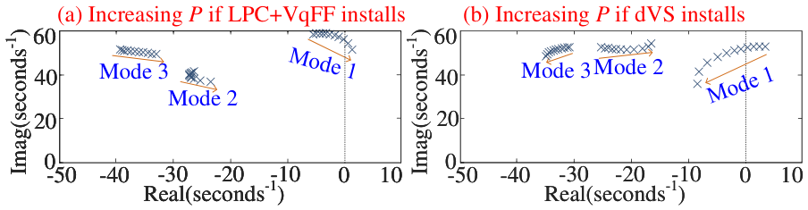
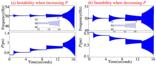
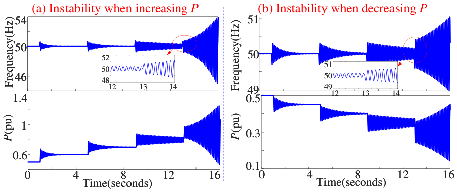
The influence of power-transfer level is examined at . Figure 18a shows the dominant-mode trajectory when LPC and VqFF are applied. Mode 1 is stable at low and moderate power levels but enters the right-half plane when the transferred power approaches pu. The time-domain response in Figure 19a confirms that increasing the power from to pu produces growing low-frequency oscillations.
Figure 18.
Pole trajectories of the LFO modes in a weak grid varying with P ranging from 0 pu to 1 pu. (a) Alongside LPC+VqFF. (b) Alongside dVS.
Figure 19.
Time-domain responses under weak-grid power variations. (a) P increased from 0.5 pu to 0.9 pu (alongside LPC+VqFF). (b) P reduced from 0.5 pu to 0.3 pu () (alongside dVS).
When only dVS is applied, Figure 18b shows the opposite power-dependent characteristic. Mode 1 is unstable at pu but becomes stable as the transferred power increases. As confirmed by Figure 19b, reducing the power from to pu leads to an unstable oscillatory response.
Therefore, DVSC reshaping becomes insufficient under weak-grid and high-power conditions, whereas dVS provides limited damping at low power. These contrasting characteristics explain why an individual stabilizing path cannot maintain adequate damping over the entire power range.
5.1.3. Composite Stabilization
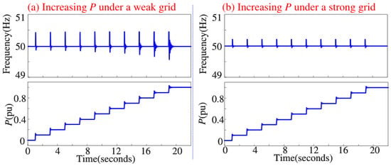
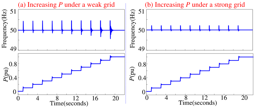
Figure 20 evaluates the composite stabilizer as the power reference varies from 0 to 1 pu under weak- and strong-grid conditions. The same controller parameters are used throughout the tests.
Figure 20.
System stability by the composite stabilizer accounting for P rising from 0 pu to 1 pu: (a) Weak grids; (b) strong grids.
In both grid conditions, the active power follows the reference changes without sustained low-frequency oscillations, and the converter frequency remains bounded around its nominal value. The results confirm that combining LPC, VqFF, dVS, and qVS extends the stable operating range compared with the individual stabilizing paths. However, the results apply to the tested system parameters and do not constitute a general stability guarantee for arbitrary grid impedances.
5.1.4. Robustness Evaluation Under Fault and Contingency Conditions
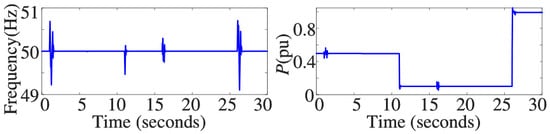
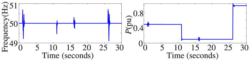
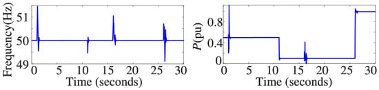
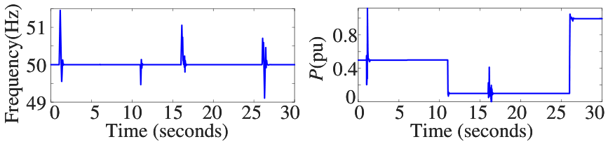
To further evaluate the robustness of the proposed composite stabilizer, severe disturbance scenarios are considered. The GFM-PV system operates with and an initial active power output of 0.5 pu. Two representative contingency scenarios are investigated. Case A considers grid voltage sag events, while Case B considers three-phase short-circuit faults at the PCC.
- Case A—Grid voltage sag events: The grid voltage drops to 0.5 pu at t = 1 s and recovers to 1 pu at t = 1.2 s. Subsequently, the PV output power changes from 0.5 pu to 0.1 pu at t = 11 s, experiences another voltage sag event from t = 16 s to t = 16.2 s, and finally increases to 1 pu at t = 26 s.
- Case B—Three-phase short-circuit faults at the PCC: A three-phase short circuit occurs at t = 1 s and is cleared at t = 1.1 s. Another fault event is applied at t = 16 s and cleared at t = 16.1 s, combined with PV power variations from 0.5 pu to 0.1 pu at t = 11 s and to 1 pu at t = 26 s.
Figure 21 and Figure 22 show the frequency and active-power responses under these two cases. The results demonstrate that although severe disturbances introduce transient oscillations in frequency and active power, the proposed composite stabilizer enables the GFM-PV system to quickly recover to the stable operating point without loss of synchronization. These results verify the robustness of the proposed control strategy under fault and contingency conditions.
Figure 21.
GFM-PV responses under grid voltage sag events (Case A).
Figure 22.
GFM-PV responses under PCC three-phase short-circuit faults (Case B).
5.2. OPAL-RT Real-Time Validation
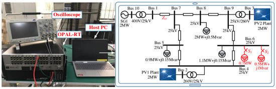
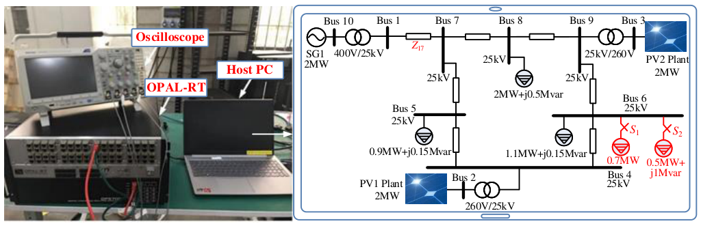
System-level verification is performed using real-time simulators from OPAL-RT. Figure 23 illustrates the test system, a scaled-down three-machine, ten-bus configuration. SG1 is a synchronous generator, equipped with autonomous frequency control. Both two PV plants are included and each consist of five 400-kW GFM-PV systems, using parameters in Table 1.
Figure 23.
Downscaled three-machine test system simulated by OPAL-RT.
During simulations, one fundamental objective is control performance. We use the same control settings, without retuning, irrespective of grid condition changes. Evaluation is made for pu (on base of MW and kV), respectively, representing a strong and weak grid.
5.2.1. Strong-Grid Scenario
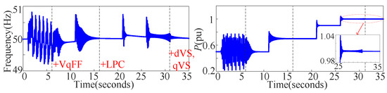
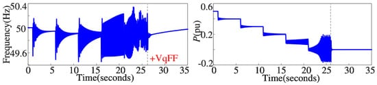
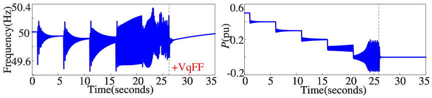
Under the strong-grid condition, PV1 operates at pu, with the complete composite stabilizer enabled. The following sequence is applied to PV2: at s, disabling all stabilizers; s, activating VqFF; s, increasing the power reference () from 0.5 pu to 0.7 pu; s, activating LPC; s, raising from 0.7 pu to 0.9 pu; s, further increasing to 1.0 pu; at s, activating dVS and qVS. Results, including frequency and active power of PV2, are illustrated in Figure 24.
Figure 24.
Dynamic responses of PV2 system in a strong grid.
As shown in Figure 24, disabling all supplementary stabilizers leads to an unstable oscillatory response. Enabling VqFF restores stability at the initial operating point. The power-reference changes at s and s excite an oscillatory mode at approximately 7.5 Hz, and the activation of LPC reduces its amplitude. When the power reference reaches 1.0 pu, the damping again becomes insufficient. Activating dVS and qVS suppresses the oscillation and restores a bounded response. The results are consistent with the eigenvalue analysis: DVSC reshaping provides useful damping in a strong grid, but the terminal-voltage stabilizers are required when the transferred power approaches the upper operating range.
5.2.2. Weak-Grid Scenarios
In this segment, we illustrate instability phenomena in weak grids. Initially, pu and pu. The following two cases are set
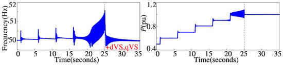
- Case C: Both PV1 and PV2 use VqFF and LPC. The test sequence for follows the steps pu at s. dVS and qVS are activated at s.
- Case D: Both PV1 and PV2 use dVS and qVS. The test sequence for is pu at s. VqFF is activated at s.
As shown in Figure 25, the oscillation amplitude increases as approaches the upper power range. Sustained instability occurs around and above pu despite the use of LPC and VqFF. After dVS and qVS are enabled, the oscillation is suppressed. This case confirms that DVSC reshaping alone may be inadequate under weak-grid and high-power conditions.
Figure 25.
Weak-grid instability with a high power transfer (Case C).
Figure 26 shows that the oscillation becomes more pronounced as the transferred power decreases and develops into an unstable response below approximately pu. Enabling VqFF provides an additional damping path and restores a bounded response. This case illustrates the limited effectiveness of the voltage stabilizers at very low power levels and the complementary role of DVSC reshaping.
Figure 26.
Weak-grid instability with a low power transfer (Case D).
5.2.3. Power-Range and Load-Disturbance Tests
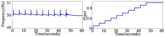
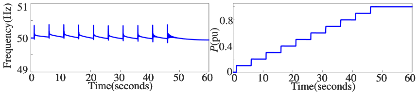
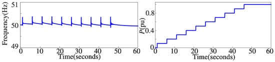
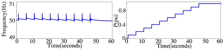
The complete composite stabilizer is subsequently evaluated with fixed parameters over a sequence of power-reference changes. PV1 operates at pu, while the reference of PV2 is increased from 0 to 1 pu through ten steps over the interval from 1 to 50 s. Figure 27 and Figure 28 show the responses under the strong- and weak-grid conditions.
Figure 27.
Power-step responses for composite stabilizer used in strong grids.
Figure 28.
Power-step responses for composite stabilizer used in weak grids.
In both cases, the converter remains synchronized and its active power follows the successive reference changes. The damping becomes weaker near the upper end of the power range, particularly in the weak-grid case, but no sustained oscillation is observed using the parameters in Table 1. This result supports the complementary operation of the four stabilizing paths over the tested power range. It also indicates that additional gain optimization may be required when a specified minimum damping ratio must be maintained at very high power levels.
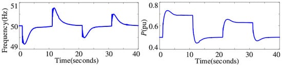
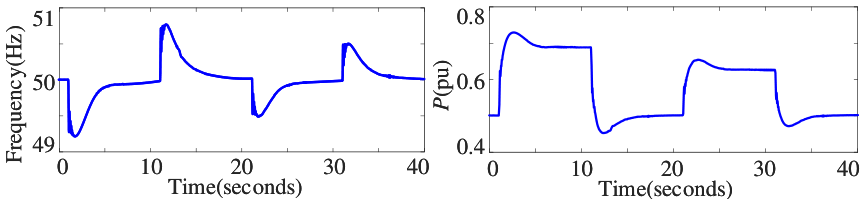
The response to load disturbances is further evaluated in a converter-dominated test system. The SG1 in Figure 23 is replaced by a 2MW GFL-PV unit, represented from the network perspective as a negative constant-power load with pu. A 0.75 MW resistive load is connected at Bus 6 at s and disconnected at s. Subsequently, a 0.5 MW +Mvar inductive load is connected at s and disconnected at s. As shown in Figure 29, each switching event produces a transient frequency and power deviation, after which the system returns to a bounded steady-state response. The test therefore confirms that the composite stabilizer retains its damping capability under the selected active- and reactive-load disturbances in the converter-dominated system.
Figure 29.
Load-step responses for the composite stabilizer in the converter-dominated test system.
6. Conclusions
This paper investigates the low-frequency stability of DVSC-based GFM-PV systems under varying grid strengths and power-transfer levels. A reduced-order small-signal model is developed to clarify the damping and synchronizing contributions of the DVSC loop, electrical network, and terminal-voltage regulation. The analysis shows that the basic DVSC loop provides no inherent damping, while the interaction among voltage regulation, grid impedance, and operating power may introduce negative damping or reduce the synchronizing margin. To address these limitations, DC-link-voltage-feedback d- and q-axis voltage stabilizers are designed and combined with DVSC reshaping methods in a composite stabilization scheme. Eigenvalue analysis, nonlinear time-domain simulations, and OPAL-RT real-time simulations demonstrate that the proposed scheme improves the damping of the dominant low-frequency modes and enlarges the stable operating region under the tested grid-strength, power-step, and load-disturbance conditions.
Author Contributions
Conceptualization, L.S. and Y.T.; methodology, L.S. and Y.T.; software, Y.T. and Q.W.; validation, L.S., Y.T., Q.W., and S.H.; investigation, L.S., Y.T., and Q.W.; resources, L.S. and H.W.; data curation, L.S. and Y.T.; writing—original draft, L.S. and Y.T.; writing—review and editing, L.S. and S.H.; visualization, L.S. and Q.W.; supervision, L.S.; project administration, L.S. and H.W.; funding acquisition, L.S. All authors have read and agreed to the published version of the manuscript.
Funding
This research was funded in part by the National Natural Science Foundation of China, grant number 52207084, and in part by Shenzhen Stable Support Project under Grant GXWD20231130163132003.
Data Availability Statement
The original contributions presented in this study are included in the article. Further inquiries can be directed to the corresponding author.
Conflicts of Interest
The authors declare no conflicts of interest. The funder had no role in the design of the study; in the collection, analyses, or interpretation of data; in the writing of the manuscript; or in the decision to publish the results.
Appendix A. Linearized Circuit and Control Equations Related to Figure 4
The DC-link voltage dynamic is used to dictate the frequency and phase of outlet voltage . Linearizing (1) yields
In this context, we use “∧" to denote the perturbed variables and the subscript “0" to represent the steady-state variables. The dynamic relationship from the active power to DC-link voltage is given by [21]
Remark A1.
(i) The grid voltage in the frame. The perturbed variables , , consequently. (ii) The filter capacitor provides a constant reactive current, where , . By coordinate transformation processing, the perturbed variables and .
With Remark A1, the linearization of (9) is
In addition,
Through coordinate transformation processing, we have
Linearizing (8) and (5) gives that
The refined small-signal model in Figure 4 can be easily established using Equations (A1)–(A6).
Appendix B. Parameter Tuning Procedure of Controllers and Stabilizers
- (1)
- DVSC gain tuning
The DVSC gain determines the relationship between DC-link voltage deviation and frequency deviation. According to the reduced-order model, the equivalent inertia associated with DVSC is inversely related to . That is, a large improves synchronization speed but reduces the equivalent inertia, while a small provides slower frequency response but improves inertia characteristics. Therefore, is selected to achieve a compromise between fast synchronization and adequate low-frequency stability margin.
- (2)
- LPC and VqFF tuning
Based on (13), the damping contribution of LPC increases with . However, excessive phase-lead compensation modifies the equivalent inertia and may deteriorate transient performance. Therefore, and are selected such that sufficient phase compensation is achieved while maintaining the desired inertia characteristics.
The VqFF gain is selected according to (15). A higher gain increases damping contribution, but excessive gain may amplify voltage-reference perturbations and reduce robustness under weak-grid conditions.
- (3)
- d/q-axis stabilizer tuning
The stabilizer gains and are selected based on the damping and synchronizing contributions obtained from (17) and (18). Since both stabilizers introduce additional damping together with synchronization modification, the gains are limited to avoid excessive synchronization-factor variation.
A moderate gain of pu is finally adopted for both stabilizers, which provides noticeable damping improvement while maintaining a positive synchronizing margin over the investigated operating range.
Appendix C. GFL Parameters
The 2 MW GFL-PV unit is represented by an aggregation of five identical 400 kW PV converter modules, and all parameters are on base of the unit rating.
filter resistance: pu, pu, pu, DC capacitor: , DC voltage: , terminal-voltage control: , DC voltage control: , current control: , PLL control: .
References
- REN21. Renewables 2025 Global Status Report; REN21: Bonn, Germany, 2025; Available online: https://pure.iiasa.ac.at/id/eprint/20705/?template=default_internal (accessed on 11 August 2026).
- Li, Y.; Gu, Y.; Green, T.C. Revisiting grid-forming and grid-following inverters: A duality theory. IEEE Trans. Power Syst. 2022, 37, 4541–4554. [Google Scholar] [CrossRef] [Scilit]
- Lin, Y.; Eto, J.; Johnson, B.; Flicker, J.; Lasseter, R.; Pico, H.V.; Seo, G.-S.; Pierre, B.; Ellis, A. Research Roadmap on Grid-Forming Inverters; Technical Report NREL/TP-5D00-73476; National Renewable Energy Laboratory: Golden, CO, USA, 2020.
- National Grid ESO. Great Britain Grid Forming Best Practice Guide; National Grid ESO: Warwick, UK, 2023; Available online: https://www.neso.energy/document/278491/download (accessed on 11 August 2026).
- Du, W.; Chen, Z.; Schneider, K.P.; Lasseter, R.H.; Nandanoori, S.P.; Tuffner, F.K.; Kundu, S. A comparative study of two widely used grid-forming droop controls on microgrid small-signal stability. IEEE J. Emerg. Sel. Top. Power Electron. 2020, 8, 963–975. [Google Scholar] [CrossRef] [Scilit]
- Denholm, P.; Brown, P.; Cole, W.; Mai, T.; Sergi, B. Examining Supply-Side Options to Achieve 100% Clean Electricity by 2035; Technical Report NREL/TP-6A40-81644; National Renewable Energy Laboratory: Golden, CO, USA, 2022.
- Singh, V.; Pattnaik, S.; Anand, V.; Neti, S.S. Comparison of two-stage and single-stage photovoltaic inverter for grid-connected system. In Proceedings of the 2024 Third International Conference on Power, Control and Computing Technologies (ICPC2T), Raipur, India, 18–20 January 2024; IEEE: New York, NY, USA, 2024; pp. 462–467. [Google Scholar]
- Tafti, H.D.; Konstantinou, G.; Townsend, C.D.; Farivar, G.G.; Sangwongwanich, A.; Yang, Y.; Pou, J.; Blaabjerg, F. Extended functionalities of photovoltaic systems with flexible power point tracking: Recent advances. IEEE Trans. Power Electron. 2020, 35, 9342–9356. [Google Scholar] [CrossRef] [Scilit]
- Hasan, M.; Imbayah, I.; Alomer, I.A.; Alsharif, A. Solar Photovoltaic Grid Forming to Evaluate Various Control Algorithms: A Review. In Proceedings of the International Conference on Emerging Technologies and Applications in Electrical Engineering, Raipur, India, 18–19 December 2024; Springer Nature: Singapore, 2024; pp. 33–40. [Google Scholar]
- Paduani, V.; Lu, N. Implementation of a two-stage PV system testbed with power reserves for grid-support applications. In Proceedings of the 2021 North American Power Symposium (NAPS), College Station, TX, USA, 14–16 November 2021; IEEE: New York, NY, USA, 2021; pp. 1–6. [Google Scholar]
- Chen, Z.; Lasseter, R.H.; Jahns, T.M. Active power reserve control for grid-forming PV sources in microgrids using model-based maximum power point estimation. In Proceedings of the 2019 IEEE Energy Conversion Congress and Exposition (ECCE), Baltimore, MD, USA, 29 September–3 October 2019; IEEE: New York, NY, USA, 2019; pp. 41–48. [Google Scholar]
- Hasabelrasul, H.; Cai, Z.; Sun, L.; Suo, X.; Matraji, I. Two-stage converter standalone PV-battery system based on VSG control. IEEE Access 2022, 10, 39825–39832. [Google Scholar] [CrossRef] [Scilit]
- Radwan, A.; Elshenawy, M.A.; Mohamed, Y.A.-R.I.; El-Saadany, E.F. Grid-forming voltage-source inverter for hybrid wind-solar systems interfacing weak grids. IEEE Open J. Power Electron. 2024, 5, 956–975. [Google Scholar] [CrossRef] [Scilit]
- Quan, X.; Yu, R.; Zhao, X.; Lei, Y.; Chen, T.; Li, C.; Huang, A.Q. Photovoltaic synchronous generator: Architecture and control strategy for a grid-forming PV energy system. J. Emerg. Sel. Top. Power Electron. 2020, 8, 936–948. [Google Scholar] [CrossRef] [Scilit]
- Ansari, A.Q.; Singh, B.; Hasan, M. Algorithm for power angle control to improve power quality in distribution system using unified power quality conditioner. IET Gener. Transm. Distrib. 2015, 9, 1439–1447. [Google Scholar] [CrossRef] [Scilit]
- Lu, M.; Dhople, S.; Johnson, B. Benchmarking nonlinear oscillators for grid-forming inverter control. IEEE Trans. Power Electron. 2022, 37, 10250–10266. [Google Scholar] [CrossRef] [Scilit]
- Yu, H.; Awal, M.A.; Tu, H.; Husain, I.; Lukic, S. Comparative transient stability assessment of droop and dispatchable virtual oscillator controlled grid-connected inverters. IEEE Trans. Power Electron. 2021, 36, 2119–2130. [Google Scholar] [CrossRef] [Scilit]
- Seo, G.S.; Colombino, M.; Subotic, I.; Johnson, B.; Groß, D.; Dörfler, F. Dispatchable virtual oscillator control for decentralized inverter-dominated power systems: Analysis and experiments. In Proceedings of the 2019 IEEE Applied Power Electronics Conference and Exposition (APEC), Anaheim, CA, USA, 17–21 March 2019. [Google Scholar]
- Guo, Z.; Wu, W. Matching synchronous machine control for improving active support of grid-forming PV systems with enhanced DC voltage dynamics. J. Mod. Power Syst. Clean Energy 2025, 13, 179–189. [Google Scholar] [CrossRef] [Scilit]
- Sang, S.; Zhang, C.; Cai, X.; Molinas, M.; Zhang, J.; Rao, F. Control of a Type-IV wind turbine with the capability of robust grid-synchronization and inertial response for weak grid stable operation. IEEE Access 2019, 7, 58553–58569. [Google Scholar] [CrossRef] [Scilit]
- Zhao, L.; Jin, Z.; Wang, X. Small-signal synchronization stability of grid-forming converters with regulated DC-link dynamics. IEEE Trans. Ind. Electron. 2023, 70, 12399–12409. [Google Scholar] [CrossRef] [Scilit]
- Huang, L.; Xin, H.; Wang, Z.; Wu, K.; Wang, H.; Hu, J.; Lu, C. A virtual synchronous control for voltage-source converters utilizing dynamics of DC-link capacitor to realize self-synchronization. IEEE J. Emerg. Sel. Top. Power Electron. 2017, 5, 1565–1577. [Google Scholar] [CrossRef] [Scilit]
- Xin, H.; Liu, C.; Chen, X.; Wang, Y.; Prieto-Araujo, E.; Huang, L. How many grid-forming converters do we need? A perspective from small-signal stability and power grid strength. IEEE Trans. Power Syst. 2025, 40, 623–635. [Google Scholar] [CrossRef] [Scilit]
- Zhao, L.; Wang, X.; Jin, Z. Impedance-based dynamics analysis for DC-link voltage-synchronized voltage-source converters. IEEE Trans. Power Electron. 2023, 38, 10829–10844. [Google Scholar] [CrossRef] [Scilit]
- Xu, C.; Zou, Z.; Liu, X.; Huang, M.; Chen, W.; Wang, Z. Stability analysis and control design of grid-forming converters with DC-link effect. IEEE Trans. Power Electron. 2025, 40, 6813–6828. [Google Scholar] [CrossRef] [Scilit]
- Kong, L.; Wu, C.; Xu, J.; Wang, J.; Wang, Y. Enhanced DC-link voltage synchronization control for grid-forming photovoltaic systems considering PV power dynamics and grid strength adaptability. IEEE Trans. Energy Convers. 2025, 40, 2610–2623. [Google Scholar] [CrossRef] [Scilit]
- Chen, Q.; Tang, Y.; Gong, D.; Lin, L.; Zeng, Q.; Shi, X. Analysis and enhancement of synchronization stability in grid-forming PV systems using torque component quantification. IEEE Trans. Energy Convers. 2025, 40, 2227–2241. [Google Scholar] [CrossRef] [Scilit]
- Mourouvin, R.; Nurminen, T.; Hinkkanen, M.; Routimo, M. Direct DC-bus control for grid-forming converters: Toward the concept of dual-voltage-forming converters. IEEE Trans. Power Electron. 2025, 40, 7789–7799. [Google Scholar] [CrossRef] [Scilit]
- Jian, A.; Huang, Z.; Chen, L.; Min, Y.; Hou, K.; Shen, Y.; Guo, F.; Yue, H. Analytical stability criterion and parameter tuning of limited grid-forming photovoltaic systems with DC voltage protection. CSEE J. Power Energy Syst. 2026, 12, 16–30. [Google Scholar] [CrossRef] [Scilit]
- Sun, L.; Pan, Y.; Wang, H. Assessing the inertial response time of grid-forming converters: Estimation and optimization. Electr. Power Syst. Res. 2026, 253, 112470. [Google Scholar] [CrossRef] [Scilit]
- Heffron, W.G.; Phillips, R.A. Effect of a modern amplidyne voltage regulator on underexcited operation of large turbine generators [includes discussion]. AIEE Trans. 1952, 71, 692–697. [Google Scholar] [CrossRef] [Scilit]
- Harnefors, L.; Schweizer, M.; Kukkola, J.; Routimo, M.; Hinkkanen, M.; Wang, X. Generic PLL-based grid-forming control. IEEE Trans. Power Electron. 2022, 37, 1201–1204. [Google Scholar] [CrossRef] [Scilit]



Disclaimer/Publisher’s Note: The statements, opinions and data contained in all publications are solely those of the individual author(s) and contributor(s) and not of MDPI and/or the editor(s). MDPI and/or the editor(s) disclaim responsibility for any injury to people or property resulting from any ideas, methods, instructions or products referred to in the content. |
© 2026 by the authors. Licensee MDPI, Basel, Switzerland. This article is an open access article distributed under the terms and conditions of the Creative Commons Attribution (CC BY) license.