


Abstract
This publication presents the results of numerical simulations concerning changes in the cold crucible design, the influence of the cold crucible melting process parameters, and the impact of the computational model on electrical efficiency and, consequently, on energy savings. The simulation was conducted in 3D, but it is limited only to electromagnetic field analysis. A total of 24 computational models were tested. Variants differed in the design of the crucible itself, the extent of charge adhesion to the crucible (operating parameters), and the charge model (charge shape, including the meniscus and cylindrical charge). Of the aspects considered, the extent of charge adhesion to the crucible bottom and walls had the greatest impact on electrical efficiency.
1. Introduction
Cold crucible melting [1,2] is one of many electrotechnological melting techniques, which also include arc furnaces [3], crucible induction furnaces [4], channel induction furnaces [5,6], and levitation melting [7,8,9]. The advantage of cold crucible melting is the lack of direct contact between the melted material and the crucible material and the heat generation directly in the heated material. A disadvantage of the cold crucible melting technique is the low melting efficiency and therefore is characterized by a relatively high specific energy consumption [10,11,12].
Cold crucible melting is most often used for melting materials (mainly metals) that are very difficult to melt (refractory metals) [13]; cold crucible melting is especially used for metals that are also highly reactive. A typical example of such a material is titanium [14,15], whose melting point is 1941 K. At high temperatures, titanium is a very reactive material, reacting with commonly used ceramic crucibles (SiO2, Al2O3, ZrO2, and MgO).
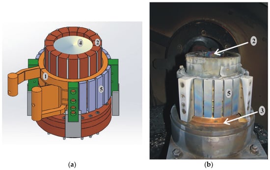
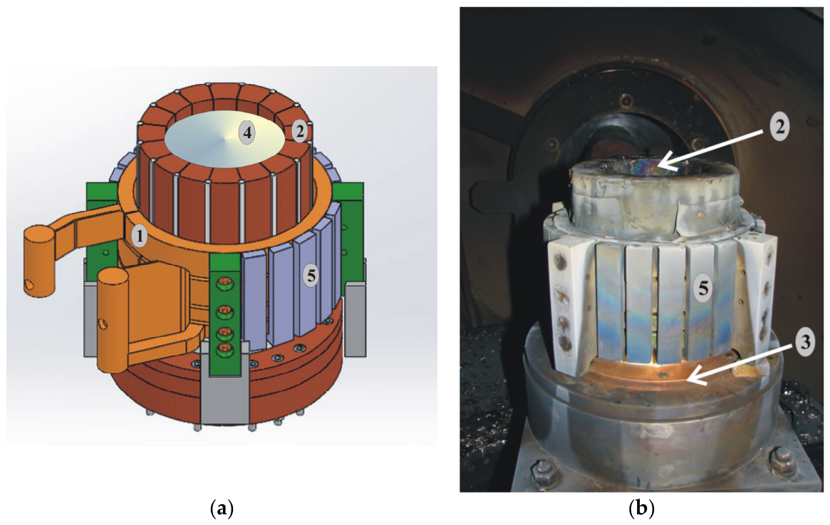
A cold crucible has a rather complex structure. It consists of an inductor winding (Figure 1, Element 1) (which is the primary source of the electromagnetic field) and water-cooled crucible fingers (Figure 1, Element 2), which form the crucible walls and act as a secondary source of the electromagnetic field. This multiple energy conversion results in a relatively low process efficiency, typically ranging from 15% to 40%. The final essential element of the crucible is the crucible bottom, also intensively cooled by water, which supports the charge. At the contact surface of the intensively cooled bottom and optionally the walls, the melted charge forms a solidified layer (skull), which naturally separates the liquid metal bath from the crucible material, ensuring high purity of melting. Alternative techniques used for melting refractory metals include: electric arc melting (remelting), used for mass production [16] (charges weighing approx. up to 23,000 kg). For very small charges (up to approx. 4 kg the melting technique using electromagnetic levitation is used [17,18].
Figure 1.
Cold crucible. (a) Construction of a cold crucible induction furnace. (b) General view. 1—inductor, 2—crucible fingers, 3—crucible bottom, 4—charge, 5—magnetic shunts.
As mentioned earlier, a disadvantage of a cold crucible induction furnace is its low melting process efficiency. This is partially due to the multiple energy transformations: electric current–electromagnetic field (inductor) → electromagnetic field–current–electromagnetic field (crucible fingers) electromagnetic field–eddy current, which is the energy source for melting the charge. However, the efficiency of a cold crucible induction furnace is also significantly influenced by
- Details of the furnace design;
- Operating parameters such as
- -
- Inductor current intensity and current frequency;
- -
- Melting charge material and crucible fill level.
This article analyzes the impact of cold crucible induction furnace design details on efficiency. The analysis is carried out using 3D modeling, taking into account only the electromagnetic field distribution, and the efficiency is calculated as the ratio of the power dissipated in the charge to the active power supplied to the inductor (Figure 1).
2. Object of Study
There are several variants of cold crucible induction furnaces. The basic division can be made based on the criterion of simultaneous melting of the charge. We differentiate between classic furnaces for melting a single charge, which have an inductor, crucible walls, and a bottom [19,20] (and this article is concerned with such designs), and furnaces for continuous melting [21], which have no bottom and solidification of the material on the crucible walls is practically non-existent.
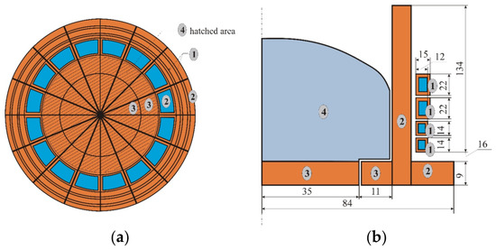
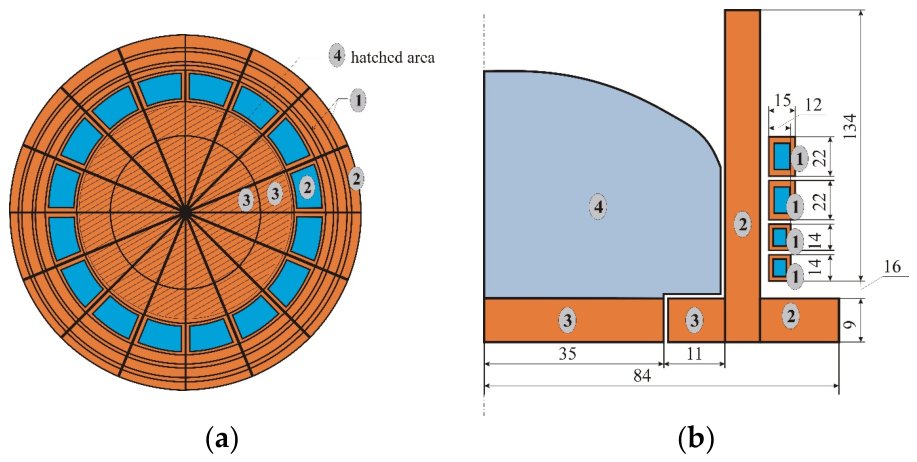
The cold crucible induction furnace shown in Figure 1 (as a general view) and in Figure 2a,b in cross-sections, is constructed with an inductor wound from water-cooled copper winding (designation 1 in Figure 1 and Figure 2). Another element of the furnace is the fingers that form the walls of the crucible, which are constructed of trapezoidal hollow elements. The furnace fingers are also intensively cooled with water. The fingers are separated around their circumference, with their number varying depending on the furnace design. The third key element of a cold crucible induction furnace is the bottom. Depending on the design, it may be connected with the fingers or have a more complex structure. The bottom of the crucible is also constructed of hollow elements and is intensively cooled. Additional elements of a cold crucible furnace may include magnetic shunts, which are used to close the magnetic field on the outer side of the inductor.
Figure 2.
Cross-sections of a cold crucible furnace: (a) cross-section; (b) longitudinal cross-section; 1—inductor; 2—fingers (crucible); 3—crucible bottom; 4—charge.
Generally, differences in the design of a cold crucible furnace may include:
- (a)
- The ratio between the diameter and height of the crucible;
- (b)
- The design and position of the inductor;
- (c)
- The structure of the fingers;
- (d)
- The structure of the bottom;
- (e)
- The presence and shape of magnetic shunts.
3. Principle of Operation of a Cold Crucible Furnace
The inductor of a cold crucible furnace is powered by an alternating current source. Typical frequency values range from 2 kHz to 10 kHz [22]. The current flowing through the inductor windings generates an alternating magnetic field. This alternating electromagnetic field incident on a surface on the crucible fingers located near the inductor, whose wall thickness is greater than the field penetration depth, induces an alternating electric current in the fingers. The current induced in the crucible fingers is the source of an electromagnetic field that appears inside the crucible and induces an alternating electric current (eddy currents) in the charge placed in the crucible. The flow of eddy currents induced in the charge heats the charge, but also creates an electromagnetic interaction between the currents flowing in the charge and in the crucible fingers. This interaction causes electromagnetic repulsion of the charge from the crucible walls. Ideally, the charge should not come into contact with the crucible walls. Crucible segmentation—the division into fingers—aims to minimize electrical losses resulting from current flow through the crucible (similar to the segmentation of magnetic cores in transformers). The number of crucible segments (number of fingers) and the shape of the fingers (proportion of radial and circular dimensions) influence power losses. Similarly, the contact of the charge with the crucible walls (fingers) affects losses, as the contacting fingers short-circuit. A similar situation occurs at the bottom of the crucible. The bottom is necessary to support the charge; the lowest field strengths occur at the center of the bottom, and this is where bottom segmentation is most often omitted. Such a solution significantly simplifies the device’s design. The segmented bottom section can be connected to the crucible fingers or can be a separate structural element. The charge in contact with the bottom solidifies, and the solidified layer of charge material “isolates” it from possible contamination by the crucible material. Furthermore, the design of the fingers and bottom is influenced by purely structural requirements, such as mounting, water flow channels, and others. To minimize magnetic field losses outside the inductor, magnetic shunts are often used [23,24]. These can have various shapes.
Copper is used for the construction of the inductor, the fingers, and the bottom of the cold crucible due to its good thermal and electrical conductivity.
The operation of a cold crucible induction furnace is also influenced by other parameters, such as the fill level of the crucible, the charge material, and the power supply parameters. If the fill level of the crucible is too low, very weak coupling occurs between the charge and the electromagnetic field, which causes losses. If the crucible is too full, very high supply currents may be required to melt the charge and generate sufficient electrodynamic forces to push the charge against the crucible walls. Operating the crucible at too high currents may create a very high meniscus, which reduces electromagnetic coupling. Operating the crucible at too low an inductor current may not result in melting or optimally pushing the charge away from the crucible walls. As the description above indicates, optimal operation of an induction furnace with a cold crucible is a complex technical compromise.
4. The Parameters Whose Impact on Efficiency Is Analyzed in This Article
The starting design for the research presented in this article is an induction furnace with a cold crucible manufactured by SECO Poland. This article examines the influence of three basic elements on furnace efficiency:
- (a)
- The design of the crucible finger (construction surplus);
- (b)
- The design of the crucible bottom;
- (c)
- The degree of separation of the charge from the crucible walls and bottom;
- (d)
- The inclusion or exclusion of a meniscus existence.
The main motivation for this article was to improve the design of an existing cold crucible furnace. Several “simple” modifications were selected that could potentially increase the system’s efficiency (a surplus, bottom separation from walls). Consideration of the impact of the finger surplus, which allows for convenient assembly of crucible segments and easy cooling water supply to the finger, arose from the suspicion that the presence of a massive conductor relatively close to the inductor winding could be a source of additional losses. Variants regarding the degree of charge adhesion to the crucible and bottom separation were considered to investigate the influence of the presence of galvanic isolation between system components on the electromagnetic efficiency.
The solutions pre-selected in this article require further verification using a complete EM-T-FD computational model.
In other publications on efficiency improvement, such as in publication [10], the authors conducted experimental research on the thermal balance of an induction furnace with a cold crucible (powered by a source with fn = 10 kHz, with a maximum power of 100 kW). In [22], the main parameter investigated in the study was the geometry of the cold crucible, specifically the shape of the crucible bottom. The effect of magnetic shunts on the efficiency increase was examined [23]. In publication [25], effects of the number of crucible segments, different segment separation configurations, and the inductor conductor geometry and distance between coils on the electrical efficiency of the system were investigated. In [26], the influence of the processed material, crucible filling level, and input power on the electrical efficiency of the furnace and the shape of the molten metal meniscus was investigated, and in [27], the authors investigated, among other things, the effect of crucible filling on efficiency and the effect of power and frequency change. They conducted calculations for a full (EM-T-FD) and very advanced calculation model. In [28], the authors focused on the optimization of the furnace electromagnetic system, with the main modification consisting of the application and design of magnetic flux controllers (MFCs), i.e., ferromagnetic components used to guide and concentrate the magnetic flux. The objective was to reduce electromagnetic losses in the cold crucible and improve power transfer to the charge (here, a cylindrical charge model is used).
4.1. Ad a and b. Crucible Finger Construction—Construction Surplus and Separation of Fingers from the Segmented Bottom
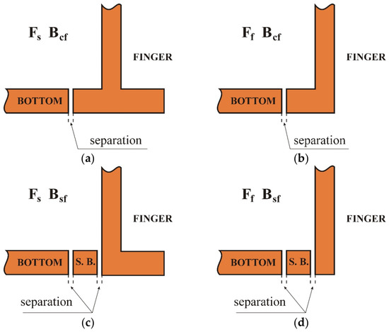
The cold crucible fingers together constitute/form the side walls of the crucible (Figure 2b and Figure 3). The fingers are radially insulated from each other and intensively cooled with water. An inductor (omitted in Figure 3) is mounted on the outer circumference of the fingers. Due to their complex mechanical design, the fingers often have an additional element (construction surplus/design surplus, Figure 3) allowing for convenient mounting of the finger to the base. This article examines how the presence of this surplus affects the efficiency of a furnace with a cold crucible. Therefore, from the perspective of the crucible finger design, two variants are distinguished:
Figure 3.
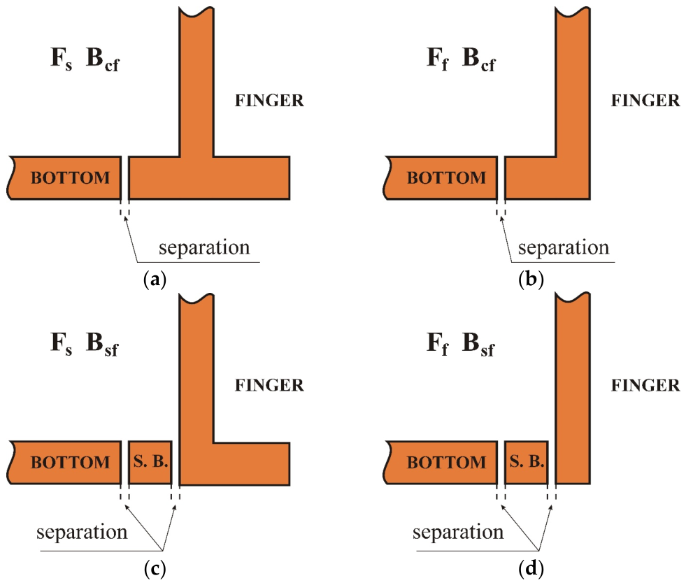
Construction of the fingers and bottom of the crucible (vertical cross-section). (a) Finger with surplus, segmented bottom connected to the finger (Fs_Bcf); (b) Finger without surplus, segmented bottom connected to the finger (Ff_Bcf); (c) Finger with surplus, segmented bottom separated from the finger (Fs_Bsf); (d) Finger without surplus, segmented bottom separated from the finger (Ff_Bsf).
The crucible bottom can be fully segmented and made in conjunction with the crucible fingers, but this design is difficult to implement (the center of the crucible bottom is a very thin “cake slice” that is difficult to cool and assemble). More often, the bottom is made as an unsegmented central section and a segmented outer section, either connected or not to the crucible fingers (Figure 3). This article considers two bottom models (the central part of the bottom is always unsegmented):
4.2. Ad c. Separation of the Charge from the Bottom and Walls of the Crucible
Depending on the magnitude of the electrodynamic forces acting on the charge, they can cause:
- For too low a force, the charge may adhere to the crucible walls and the entire bottom surface;
- For higher force values, the charge may be pushed away from the crucible walls and adhere to the entire bottom surface;
- For even higher electrodynamic forces, the charge may be pushed away from the crucible walls and the segmented part of the bottom.
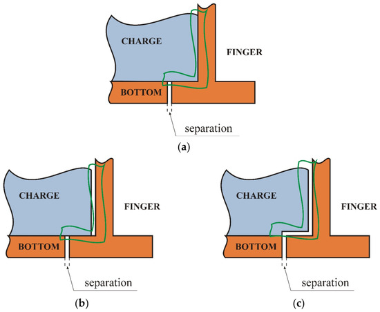
These three variants of charge adhesion to the crucible fingers and bottom are considered in this article:
- Ccfcb—charge adhered to the crucible fingers and the bottom of the crucible (Charge connected to finger; connected to bottom);
- Csfcb—charge separated from the crucible fingers but connected to the bottom of the crucible (Charge separated from finger; connected to bottom);
- Csfsb—Charge separated from the crucible fingers and separated from the crucible bottom in the segmented section (Charge separated from finger; separated from bottom).
The variants described above are shown in Figure 4 for the case where the segmented finger has a surplus (Fs) and the segmented bottom is connected to the finger (Bcf).
Figure 4.
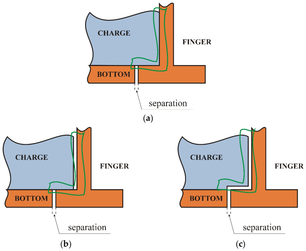
Variants differing in the separation of the charge from the bottom and walls of the crucible (marked with a green line). (a) no separation (Ccfcb); (b) separation only from the walls of the crucible (Csfcb); (c) separation from the bottom and walls (Csfsb).
The adopted separation model in the calculations themselves is a significant simplification, as separation from the crucible bottom and walls was modeled as a narrow air gap. In reality, the bath shape changes, assuming an oval/elipsoid of revolution. This simplification can be considered the best case for this type of separation because, on the one hand, it provides electrical insulation, and on the other hand, due to the very small gap width, it also ensures relatively good electromagnetic coupling.
4.3. Ad d. Considering the Presence or Absence of a Meniscus
As a result of electromagnetic fields interaction, an electrodynamic force appears, pushing the charge away from the crucible walls and bottom. At the bottom of the crucible, where the bath hydrostatic pressure is high, this force merely creates a gap between the charge and the crucible walls and bottom. At the top of the crucible, where the liquid pressure is lower, electrodynamic forces cause the formation of a meniscus. Depending on the type and quantity of material, the design of the crucible fingers, the design of the inductor, and the power supply parameters, this meniscus can be very high. A large meniscus height reduces efficiency by reducing the electromagnetic coupling between the electromagnetic field induced by the crucible fingers and the charge. A large meniscus height also increases the free surface area of the metal, which increases the intensity of bath cooling (radiation, convection). Taking the meniscus into account significantly affects the efficiency of the melting process in a cold crucible. For the purposes of this article, the meniscus was not calculated; its shape was arbitrarily adopted (based on the authors’ experience, the meniscus shape for this experiment was selected based on [29]).
The model includes two variants regarding the meniscus:
- Mp—presence of a meniscus (Meniscus presence);
- Ml—absence of a meniscus (Meniscus lack).
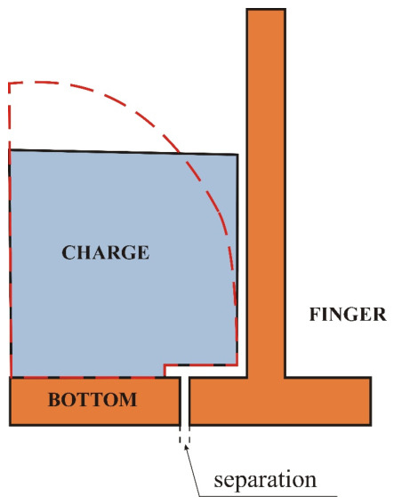
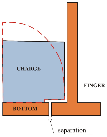
The absence of a meniscus means that the charge is approximately cylindrical. This is a common simplification of the calculation model [25,30]. This experiment demonstrates how this simplification affects the obtained calculation results. From an operational perspective, it would be best if the charge had no meniscus, meaning it had minimal surface area and maximum electromagnetic coupling. Figure 5 shows the absence of a meniscus and the presence of a meniscus for the Fs_Bcf_Csfsb case.
Figure 5.
Presence of a meniscus and absence of a meniscus for the case when the finger has a surplus, the segmented bottom is connected to the finger, and the charge is not connected to the bottom and fingers (Fs_Bcf_Csfsb).
5. Computational Model and Its Verification
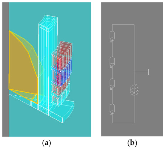
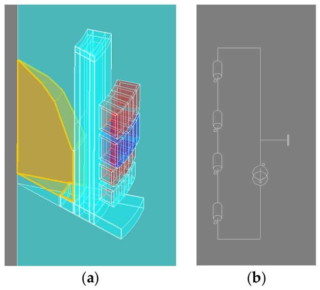
The efficiency calculations for the cold-crucible induction furnace were performed as a computer simulation. The simulation was performed only for the electromagnetic field calculations. The model was limited to 1/16 of the total geometry (assuming the cold-crucible induction furnace has 16 fingers) with appropriate boundary conditions. The 3D model is as follows (Figure 6a). A cyclic condition was assumed at the segment boundaries, and a current excitation was assumed at the intersection of the inductor windings using a circuit model (Figure 6b).
Figure 6.
(a) Computational model–volumes; (b) computational model–electric circuit.
The calculations were based on the description of the electromagnetic field using the current vector potential and magnetic scalar potential (1), (2) [31].
where
- ρ—electrical resistivity, Ω·m;
- T—current vector potential, , satisfies the relation (2) [31];
- µ—magnetic permeability, ;
- ϕ—reduced magnetic scalar potential, A.
- J—current density, .
The calculations were performed using the Flux program. The electromagnetic efficiency defined as (3) was selected as the basic resultant quantity:
where
- ηel—electromagnetic efficiency, %;
- Pjc—Joule losses in charge, W, (4) [32];
- Pjtot—Joule losses in the entire domain (total) (4), W.
- E—Electric field strength, ;
- J*—conjugate value to J—current density, .
The computational model is quite difficult to model numerically due to the lack of symmetry of the system and the large disparity in the relative dimensions of the object (narrow gaps, narrow current flow areas due to proximity and skin effects, and relatively large external dimensions of the crucible). The computational mesh was appropriately densified in the skin current flow areas in the inductor, crucible walls, and external areas of the charge. In total, the second-order computational mesh has 278,208 nodes and 173,172 volumetric elements. As previously mentioned, the starting structure for the multi-variant studies was the design of an actual furnace with a cold crucible. For the existing furnace, calibration calculations of the presented computational model were performed for the following variant (consistent with the actual furnace design): crucible fingers with surplus (Section 4.1—designation Fs); segmented bottom connected to the crucible finger (Section 4.1 designation Bcf); the charge adhered only to the unsegmented bottom (Section 4.2—designation Csfsb); and the charge has a meniscus (Section 4.3—designation Mp). The calculations were performed for 0.000468 m3 of charge made of aluminum with an electrical conductivity of 37.7 × 10⁶ S/m, for a current input of I = 4000 A (RMS) and a frequency of 8000 Hz. For the calculations, it was assumed that the crucible was made of copper, and the copper conductivity was 59.6 × 10⁶ S/m. To calibrate the model, an experimental melting was conducted on the Seco–Warwick cold-crucible system. During the measurement verification of the model, only the inductor current, frequency, and active power were checked on the Seco–Warwick furnace (the power value was read from the generator control panel). A CWT60xb Rogowski coil probe (Conrad Electronic SE, Hirchau, Germany) and a Tektronix THS720p oscilloscope (Tektronix, Cedar Hills, OR, USA) were used to measure the inductor current.
During experimental melting, for the inductor current of 4053 A and frequency of 7925 Hz, the active power of the generator was 80,000 W. On the other hand, from simulation calculations for the current forcing of 4000 A and frequency of 8000 Hz, it was calculated that the power supplied to the system (inductor, crucible, charge) was 78,307.74 W, i.e., the difference is 1692 W, which is about 2% of the deviation. The authors concluded that such a concordance of the results proves the correctness of the computational model. Unfortunately, the voltage on the exciter was not measured because the generator works in a series resonance system (a very high voltage and not a measurable value for us).
Model Sensitivity Analysis to the Discretization Mesh
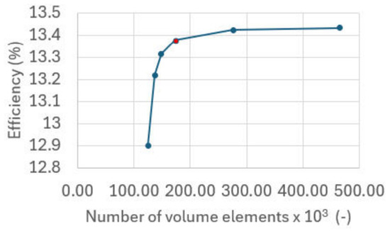
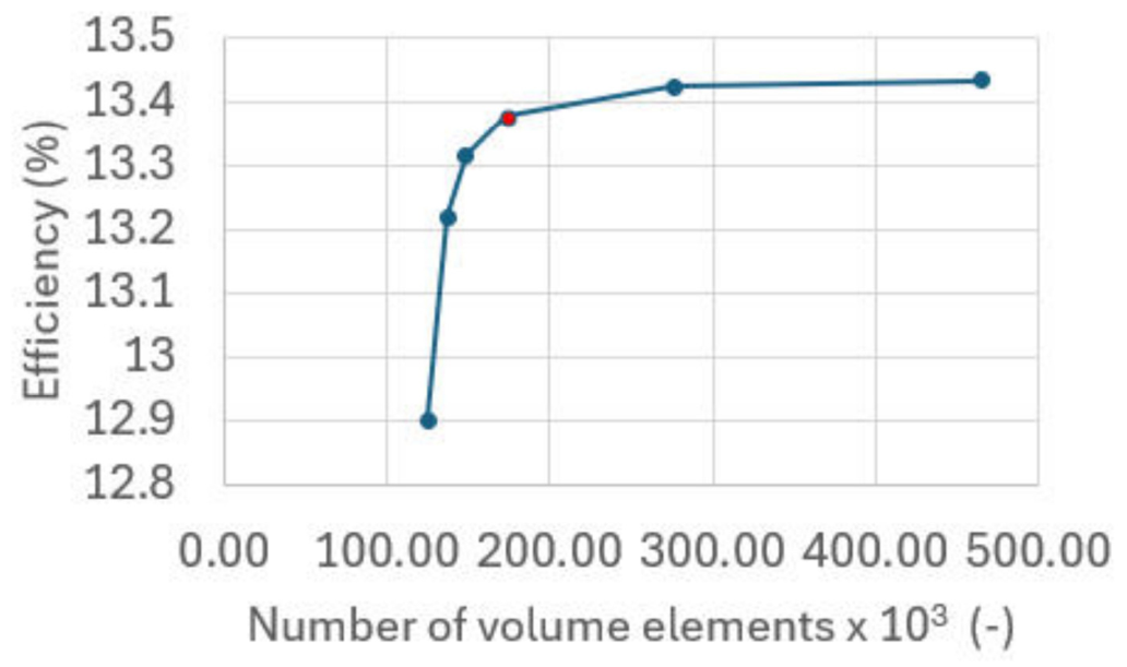
The model’s sensitivity to mesh density was performed only for the model Mp Fs_Bfc_Csfsb. Six variants of calculations were performed for the following mesh densities: 124.74 × 10³; 137.05 × 10³; 148.24 × 10³; 173.17 × 10³; 275.77 × 10³; 465.77 × 10³. The values indicate the number of volume elements after model discretization. Models for which the mesh had 173.17 × 10³ volume elements were selected for the calculations. The change in efficiency with increasing mesh density is presented in Figure 7.
Figure 7.
Influence of mesh density on efficiency.
The results of the computational model differ from the results for the model with the densest mesh considered by approximately 0.5%. It can be assumed that from the discretization point of view, the obtained results are correct with an uncertainty of ±0.025%.
The model discretization took into account the issues of field penetration depth and proximity effect; the mesh was denser in the inductor walls adjacent to the crucible and other coils (the inductor wall thickness of 2 mm was divided into four geometric elements with the minimum distance (0.3 mm and coefficient R = 1.5)). A similar division was made in the crucible walls, which were 4 mm thick. The field penetration depth for the inductor and crucible walls (copper with a resistivity of 1.72 × 10⁻⁸ Ω·m was assumed for the calculations) is 0.739 mm, while for the charge (aluminum), the field penetration depth is 0.916 mm.
6. Discussion of the Calculation Results
The computational experiment involved determining the electromagnetic efficiency for various design variants of an induction furnace with a cold crucible. A total of 24 calculation variants were performed, described in detail in Section 4.
All obtained efficiency results are presented in Table 1 and Table 2, where Table 1 contains the results for models including the meniscus, and Table 2 contains the results for models without including the meniscus.
Table 1.
The results for models including the meniscus.
Table 2.
The results for models without including the meniscus.
6.1. The Effect of Crucible Finger Surplus on Efficiency
In all cases, the presence of crucible finger surplus (Figure 3a or Figure 3c) increases efficiency, although the increase is very small, reaching a maximum of 0.12 percentage points, which represents 2.0% of the efficiency. The largest increase occurred for the model with a meniscus, a segmented bottom connected to the crucible fingers, and the charge adjacent to the bottom and the crucible fingers (Table 1, Fs_Bcf_Ccfcb and Ff_Bcf_Ccfcb).
6.2. The Effect of Separating the Bottom from the Crucible Fingers
Separating the segmented bottom from the crucible fingers (Figure 4c) results in an efficiency increase for all cases considered (Table 3 and Table 4). The efficiency increase is quite large, reaching a maximum of 8.6% (minimum only 1.18%). The largest efficiency increase was observed for the model including the meniscus; the crucible fingers had a surplus, and the charge adhered to the crucible bottom but was separated from the crucible walls (Table 3, variant Fs_Csfcb).
Table 3.
Comparison of efficiency depending on the separation of the bottom from the fingers for a charge with a meniscus.
Table 4.
Comparison of efficiency depending on the separation of the bottom from the fingers for a charge without a meniscus (cylindrical).
All calculations on the data contained in the tables were performed with full precision (13 decimal places) and then rounded to the second decimal place.
6.3. Impact of Taking into Account the Bath Meniscus on Efficiency Calculations
Taking into account a meniscus or the absence of a meniscus (cylindrical charge) significantly affects the simulation results. These calculations were performed because some publications [25,29] use the simplification of assuming a cylindrical charge (in which case, it is always assumed that the charge is adhered to the bottom, but not to the crucible wall). As can be seen in Table 5, for variants in which the charge is not in contact with the fingers/crucible wall (melting process conducted correctly), calculations for a cylindrical charge always yield higher efficiency. The efficiency gains are significant. The largest gain was obtained for the variant where the fingers had no surplus, the segmented bottom was connected to the fingers, and the charge was adhered to the bottom and separated from the fingers (Ff_Bcf_Csfcb), with an efficiency gain of 21.63% (the smallest efficiency gain was 15.57%). Calculations for the model without a meniscus can be considered the most optimistic case—the case with the highest achievable efficiency. For variants where the charge adheres to the bottom and wall of the crucible (grayed variants in Table 5), lower efficiency was obtained for the cylindrical model. From a technical perspective, if the charge adheres to the crucible wall (closes the fingers), the melting process is conducted incorrectly. The larger the contact area of the charge with the crucible wall, the lower the efficiency. In this case, the higher efficiency for the model with a meniscus results from simple geometry. For the simplification adopted in this publication, for a charge with a meniscus, in the section of the charge near the bottom of the crucible, the separation of the charge from the crucible walls is modeled using a very narrow gap. If a charge of identical volume is modeled as cylindrical, its contact area with the crucible wall is smaller than the contact area of the charge for which the meniscus was modeled (see Figure 5). In this computational experiment, the cylindrical charge was in contact with the crucible wall (covering the crucible fingers) over a length of 74 mm, while the charge with a meniscus was in contact with the crucible wall (covering the crucible fingers) only over a length of 46.7 mm.
Table 5.
Comparison of efficiency depending on the presence or absence of a meniscus.
6.4. The Effect of Charge-Bottom Contact on Efficiency
The study of variants differing in charge adhesion to the segmented bottom (Figure 4c) and non-adhesion to the segmented bottom (Figure 4b) was limited to variants for which the charge did not adhere to the crucible walls. The experimental results are presented in Table 6 for cases where the charge meniscus was taken into account, and in Table 7 for cases where the charge did not. For all variants considered, the efficiency for the case where the charge was not in contact with the segmented bottom (it was supported only in the central part of the crucible on the non-segmented bottom) was higher than the efficiency when the charge adhered to the entire bottom. The maximum efficiency difference is 7.40% and occurs when the crucible finger has a surplus, the segmented bottom is connected to the crucible finger, and the charge is modeled as having a meniscus (Mp Fs_Bcf). Additionally, it can be noted that for cases where the segmented bottom is separated from the crucible finger, the efficiency difference also occurs, but is approximately half as large. This suggests that, from the perspective of the electromagnetic efficiency of the melting process in a cold crucible, it is more advantageous to separate the crucible bottom from the fingers/crucible walls.
Table 6.
Change in efficiency depending on the adhesion of the charge to the segmented bottom for the model with a meniscus.
Table 7.
Comparison of efficiency depending on the adhesion of the bottom from the fingers for a charge without a meniscus (cylindrical).
6.5. The Effect of Charge Adhesion to Crucible Walls on Efficiency
As indicated by the results in Table 8 and Table 9, cases where the charge adheres to the crucible wall significantly reduce the electrodynamic efficiency of a furnace with a cold crucible, regardless of its design. A comparison was made between variants where the charge adheres to the entire bottom, i.e., variants differing only in their adhesion to the crucible walls (Csfcb and Ccfcb). The largest change in efficiency was as much as 66.05% for the variant where the charge had no meniscus modeled, the finger had no surplus, and the segmented bottom was separated from the finger (variants (Ml Ff_Bsf_Csfcb and Ml Ff_Bsf_Ccfcb)). However, for the remaining variants, the change in efficiency was only slightly smaller, always exceeding 50%. An important conclusion can be drawn from this: the design of the cold crucible furnace and the conditions of the melting process must ensure that the charge is pushed away from the crucible walls.
Table 8.
Change in efficiency depending on the adhesion of the charge to the crucible wall for the model with a meniscus.
Table 9.
Change in efficiency depending on the adhesion of the charge to the crucible walls for the model without meniscus.
7. Summary and Conclusions
This article presents the results of 24 numerical simulations for various computational models of a cold crucible induction furnace. The differences concerned:
- Furnace design (the shape of the fingers constituting the crucible walls; separation of the segmented bottom from the crucible fingers);
- Adherence of the charge to the segmented bottom and crucible walls (these differences may result from the furnace design or melting process conditions);
- Modeling of the charge shape (charge with a meniscus and charge without a meniscus). This aspect of the study concerns only a typical simplification often used in calculations.
Since the presented results are numerical calculations, they are not subject to generalization, and the presented conclusions concern the results of the simulation performed.
The results obtained in this experiment indicate that:
- The most significant impact on the electromagnetic efficiency of a cold crucible induction furnace is the fact that the metal bath contacts the crucible fingers (charge adhesion to the crucible wall). Charge adhesion to the crucible wall may result from improper furnace design or poor melting procedures (too much charge, too low an inductor current). The efficiency drop for cases where the charge adheres to the crucible walls is above 50% for all variants, and as much as 66.05% for the variant with the greatest efficiency drop. Such a strong reduction in efficiency causes a serious increase in energy consumption, which may call into question the economic sense of using this technology.
- The second most significant factor influencing the efficiency change was the adopted charge model. Depending on whether the charge was modeled as cylindrical (without a meniscus) or with a meniscus, the efficiency change was 21.63%. With the exception of four cases where the charge adhered to the crucible walls, modeling the charge as cylindrical resulted in an efficiency increase. This increase ranges from 15.57% to 21.63%. Therefore, the calculation model with a cylindrical charge should be considered as simplified, and the obtained results should be considered as the best possible (optimistic) results.
- Separating the segmented bottom from the crucible fingers (walls) results in an efficiency increase of up to 8.6%.
- The charge short-circuiting the segmented bottom—the charge adhering to the entire bottom surface causes a decrease in efficiency of up to 7.4%.
Disregarding the variants for which a cylindrical charge shape was assumed (a significant simplification of the model), the highest efficiency, among all the cases considered in this publication, was achieved for the variant where the crucible finger had a surplus, the segmented bottom was separated from the finger, and the charge adhered only to the central part of the bottom (Fs_Bsf_Csfsb). The efficiency for this case was 14.07%. This indicates that the best crucible design was the one where the finger had a surplus and the crucible bottom was separated from the fingers constituting the crucible walls.
As the analysis shows, the significant impact of the parameters under consideration on efficiency suggests that for industrial applications, the design of a cold crucible induction furnace and its operating parameters should be precisely selected for the type and volume of the melted charge, which guarantees a reduction in energy consumption.
To make the results of the numerical experiment conducted here more reliable, the multi-variant calculations should be extended to a different charge material (by changing the charge resistivity) and also extended to various crucible filling levels. For the highest-efficiency variants, the authors also plan verification calculations using the full EM-T-FD calculation model. The full calculation model addresses the shortcomings of the calculation model presented here (the unrealistic shape of the gap between the charge and the crucible and the simplified shape of the meniscus). The full calculation model, of course, also allows for the consideration of thermal losses, which are a very important factor in the case of an induction furnace with a cold crucible.
Author Contributions
Conceptualization, P.R.; methodology, P.R.; validation, P.R.; formal analysis, P.R.; investigation, P.R. and S.A.; resources, S.A.; data curation, S.A.; writing—original draft preparation, P.R.; writing—review and editing, P.R. and S.A.; visualization, S.A.; supervision, S.A. All authors have read and agreed to the published version of the manuscript.
Funding
This research was funded by Silesian University of Technology, grant numbers 11/040/BK_26/0043 and 11/990/BK_26/0092.
Data Availability Statement
Data are contained within the article.
Conflicts of Interest
The authors declare no conflicts of interest.
Nomenclature/Abbreviations
| Symbol | Definition | Units |
| 3D | Three-dimensional | |
| Al2O3 | Aluminum oxide | |
| EM-T-FD | Electromagnetic field–temperature field–fluid dynamics | |
| MFCs | Magnetic flux controllers | |
| MgO | Magnesium oxide | |
| SiO2 | Silicon dioxide | |
| ZrO2 | Zirconium dioxide | |
| E | Electric field strength | |
| fn | Nominal frequency | Hz |
| J | Current density | |
| J* | Conjugate value to J—current density | |
| kHz | Kilohertz | Hz |
| kW | Kilowatt | W |
| RMS | Root Mean Square | |
| Pjc | Joule losses in charge | W |
| Pjtot | Joule losses in entire domain | W |
| T | Current vector potential | |
| ηel | Electromagnetic efficiency | % |
| µ | Magnetic permeability | |
| ρ | Electric resistivity | Ω·m |
| ϕ | Reduced magnetic scalar potential | A |
References
- Durand, F. The Electromagnetic Cold Crucible as a Tool for Melt Preparation and Continuous Casting. Int. J. Cast Met. Res. 2005, 18, 93–107. [Google Scholar] [CrossRef] [Scilit]
- Quintana, I.; Azpilgain, Z.; Pardo, D.; Hurtado, I. Numerical Modeling of Cold Crucible Induction Melting. In Proceedings of the COMSOL Conference Proceedings, Stuttgart, Germany, 26–28 October 2011. [Google Scholar]
- Retech Systems LLC. VAR-T Bulletin; Retech Systems LLC: Buffalo, NY, USA, 2023; Available online: https://www.retechsystemsllc.com/wp-content/uploads/2024/07/retech-var-t-bulletin_20230612.pdf (accessed on 22 June 2026).
- Dotsch, E.; Nacke, B. Components and Design of Induction Crucible Furnaces. In ASM Handbook: Induction Heating and Heat Treatment; ASM International: Materials Park, OH, USA, 2014. [Google Scholar] [CrossRef] [Scilit]
- Wang, Z.; Li, Y.; Wang, X.; Li, X.; Yang, Q.; Hong, X. Channel-Type Induction Heating Tundish Technology for Continuous Casting: A Review. Materials 2023, 16, 493. [Google Scholar] [CrossRef] [Scilit] [PubMed]
- Ludtke, U.; Tran Thi Hang, N. Numerical Simulation of Channel Induction Furnace to Investigate Efficiency for Low Frequencies. In Proceedings of the VIII International Scientific Colloquium Modelling for Materials Processing, Riga, Latvia, 21–22 September 2017. [Google Scholar]
- Boikov, A.; Payor, V. The Present Issues of Control Automation for Levitation Metal Melting. Symmetry 2022, 14, 1968. [Google Scholar] [CrossRef] [Scilit]
- Spitans, S.; Baake, E.; Sehring, B.; Franz, H. New Method for a Large-Scale Levitation Melting and Casting of Titanium Parts. In Proceedings of the Titanium Europe Conference, Amsterdam, The Netherlands, 14–16 May 2018. [Google Scholar]
- Golak, S.; Wycislik, J.; Zybala, R.; Hanusek, R. Numerical Modeling and Optimization of Large-Scale Molten Titanium Levitation. Materials 2025, 18, 1268. [Google Scholar] [CrossRef] [Scilit] [PubMed]
- Chamorro, X.; Herrero-Dorca, N.; Bernal, D.; Hurtado, I. Induction Skull Melting of Ti-6Al-4V: Process Control and Efficiency Optimization. Metals 2019, 9, 539. [Google Scholar] [CrossRef] [Scilit]
- Przylucki, R.; Golak, S.; Bulinski, P.; Smolka, J.; Palacz, M.; Siwiec, G.; Lipart, J.; Blacha, L. Analysis of the Impact of Modification of Cold Crucible Design on the Efficiency of the Cold Crucible Induction Furnace. IOP Conf. Ser. Mater. Sci. Eng. 2018, 355, 012009. [Google Scholar] [CrossRef] [Scilit]
- Umbrashko, A.; Baake, E.; Nacke, B.; Kirpo, M.; Jakovics, A. Improvement of the Cold Crucible Melting Process Using LES Modelling. In Proceedings of the 15th Riga and 6th PAMIR Conference on Fundamental and Applied MHD, Rigas Jurmala, Latvia, 27 June–1 July 2005. [Google Scholar]
- Takaki, S.; Abiko, K. Purification of Cobalt, Nickel, and Titanium by Cold-Crucible Induction Melting in Ultrahigh Vacuum. Mater. Trans. 2006, 47, 156–161. [Google Scholar] [CrossRef] [Scilit]
- Bojarevics, V.; Nishimura, T.; Matsuo, D. Development of Advanced Cold Crucible Melting of Titanium Alloys. Magnetohydrodynamics 2022, 58, 13–24. [Google Scholar] [CrossRef] [Scilit]
- Shibata, K.; Otsuka, T.; Yamamura, K. Large Scale Cold Crucible Levitation Melting Furnace for Titanium. In Proceedings of the 8th International Conference on Electromagnetic Processing of Materials, Cannes, France, 12–16 October 2015. [Google Scholar]
- Rot, D.; Jirinec, J. Preliminary Experiments While Designing a Cold Crucible for Metal Melting. ASME J. Nucl. Radiat. Sci. 2019, 5, 030911. [Google Scholar] [CrossRef] [Scilit]
- Spitans, S.; Baake, E.; Jakovics, A. Large Scale Electromagnetic Levitation Melting of Metals. Int. J. Appl. Electromagn. Mech. 2017, 53, S61–S66. [Google Scholar] [CrossRef] [Scilit]
- Nycz, B.; Przylucki, R.; Malinski, L.; Golak, S. A Simulation Model for the Inductor of Electromagnetic Levitation Melting and Its Validation. Materials 2023, 16, 4634. [Google Scholar] [CrossRef] [Scilit] [PubMed]
- Golak, S.; Przylucki, R.; Smolka, J.; Bulinski, P.; Cieplinski, P. Influence of Cold Crucible Geometry Parameters on Electrical Efficiency. Int. J. Appl. Electromagn. Mech. 2018, 56, 165–172. [Google Scholar] [CrossRef] [Scilit]
- Smalcerz, A.; Oleksiak, B.; Siwiec, G. The influence a crucible arrangement on the electrical efficiency of the cold crucible induction furnace. Arch. Metall. Mater. 2015, 60, 3A. [Google Scholar] [CrossRef] [Scilit]
- Li, W.-D.; Bai, R.-R.; Jiang, H.; Sun, M.-H.; Qiao, H.-B.; Zhao, C. Effect of Current Frequency on Composition and Microstructure Distribution in Semi-Continuous Induction Melted TA17 Titanium Alloy Ingots. Vacuum 2026, 252, 115488. [Google Scholar] [CrossRef] [Scilit]
- Wang, G.; Bai, Y.; Zhao, B.; Li, L.; Liu, Y.; Zhang, K.; Liu, Y.; Yu, K. Improve the Performance of Cold Crucible Used for Emissivity Measurement of Molten Metal. Case Stud. Therm. Eng. 2025, 68, 105898. [Google Scholar] [CrossRef] [Scilit]
- Nemkov, V. Magnetic Flux Control in Induction Installations. In Proceedings of the International Conference on Heating by Electromagnetic Sources, Padua, Italy, 21–24 May 2013. [Google Scholar]
- Goldstein, R. Magnetic Flux Controllers in Induction Heating and Melting. In ASM Handbook, Volume 4C: Induction Heating and Heat Treatment; ASM International: Materials Park, OH, USA, 2014. [Google Scholar]
- Zhang, C.; Zhang, L.; Cao, F.; Jin, Z.; Cao, G.; Shen, H.; Huang, Y.; Sun, J. Optimizing Energy Efficiency in Induction Skull Melting Process: Investigating the Crucial Impact of Melting System Structure. Sci. Rep. 2024, 14, 6303. [Google Scholar] [CrossRef] [Scilit] [PubMed]
- Bojarevics, V.; Harding, R.A.; Pericleous, K.; Wickins, M. The Development and Experimental Validation of a Numerical Model of an Induction Skull Melting Furnace. Metall. Mater. Trans. B 2004, 35, 785–803. [Google Scholar] [CrossRef] [Scilit]
- Umbrasko, A.; Baake, E.; Nacke, B.; Jakovics, A. Thermal and Hydrodynamic Analysis of the Melting Process in the Cold Crucible Using 3D Modeling. Heat Transf. Res. 2008, 39, 413–421. [Google Scholar] [CrossRef] [Scilit]
- Nemkov, A.; Goldstein, R.; Jackowski, J. Modeling and Optimization of Cold Crucible Furnaces for Melting Metals; Fluxtrol Inc.: Auburn Hills, MI, USA, 2013; Available online: https://www.fluxtrol.com/wp-content/uploads/2025/02/MODELING-AND-OPTIMIZATION-OF-COLD-CRUCIBLE-FURNACES-FOR-MELTING-METALS.pdf (accessed on 24 July 2026).
- Palacz, M.; Melka, B.; Wecki, B.; Siwiec, G.; Przylucki, R.; Bulinski, P.; Golak, S.; Blacha, L.; Smolka, J. Experimental Analysis of the Aluminium Melting Process in Industrial Cold Crucible Furnaces. Met. Mater. Int. 2020, 26, 695–707. [Google Scholar] [CrossRef] [Scilit]
- Sauvage, E.; Brun, P.; Lacombe, J.; Aufore, L. 3D Simulation of a 500 kg UO2 Melt in a Cold Crucible. Magnetohydrodynamics 2017, 53, 267–272. [Google Scholar] [CrossRef] [Scilit]
- Kuczman, M. Potential Formulations in Magnetics Applying the Finite Element Method (Lecture Notes); Szechenyi Istvan University: Gyor, Hungary, 2009; Available online: https://www.mikrocontroller.net/attachment/642256/magnetic.pdf (accessed on 9 June 2026).
- Altair Flux Documentation. Explanation of Results: Powers and Losses. Available online: https://help.altair.com/flux/Flux/Help/english/UserGuide/English/topics/InterpretationDesResultatsPuissancesEtPertes.htm (accessed on 9 June 2026).

Disclaimer/Publisher’s Note: The statements, opinions and data contained in all publications are solely those of the individual author(s) and contributor(s) and not of MDPI and/or the editor(s). MDPI and/or the editor(s) disclaim responsibility for any injury to people or property resulting from any ideas, methods, instructions or products referred to in the content. |
© 2026 by the authors. Licensee MDPI, Basel, Switzerland. This article is an open access article distributed under the terms and conditions of the Creative Commons Attribution (CC BY) license.