


Abstract
High-temperature heat pumps are a promising pathway for electrifying industrial process heat, but their application to large-temperature-glide duties remains technically challenging. Milk powder spray drying is one such application, requiring air heating to approximately 200 °C while offering only low-to-medium-temperature waste heat sources. Transcritical CO2 heat pumps are attractive for this duty because the sensible cooling profile of supercritical CO2 can be matched to the large temperature glide of air heating. However, the high operating pressures required in transcritical CO2 cycles lead to substantial expansion losses, creating a potential opportunity for expansion work recovery. This study evaluates ejector- and expander-based expansion work recovery in high-temperature transcritical–transcritical CO2 heat pump cycles for spray dryer air heating. Baseline and modified cycle configurations were modelled using steady-state thermodynamic analysis and compared using heating coefficient of performance, maximum achievable sink temperature, component-level exergy destruction, and discharge-pressure sensitivity. Under the investigated conditions and assumed component efficiencies, expanders improved the COP of all evaluated cycles. TTX-2 achieved a COP of 2.35, 5.4% above its corresponding TT-2 baseline. TT-2 and the external benchmark TT-4 each achieved a COP of 2.23 at 150 bar for the investigated duty. The comparison with TT-4 is a benchmark comparison, not an evaluation of a TT-4 recovery variant. The improvement was modest, and an upper-bound break-even expander cost of approximately 150 EUR/kW of delivered heat was estimated for the most favourable expander case. Ejector cycles reduced expansion losses in some cases but did not provide a clear cycle-level COP improvement because they altered compressor pressure ratios, gas-cooler outlet conditions, and cascade heat transfer performance. These findings apply to the investigated spray dryer duty and demonstrate that reducing expansion exergy destruction alone is insufficient to guarantee improved whole-cycle performance under the stated operating and component-efficiency assumptions.
1. Introduction
Industrial process heating is a major challenge for decarbonisation because it is still commonly supplied by the combustion of fossil fuels and often requires heat at temperatures in excess of 100 °C that are difficult to electrify efficiently. Food, dairy and meat processing are important examples, with evaporation, drying, cleaning and hot-water services consuming substantial thermal energy across multiple temperature and spatial levels, creating distinct opportunities for heat pump integration [1]. Fossil-fuelled boilers have traditionally met industrial process heating demand. Boilers can provide high-temperature heat readily, reliably and flexibly. However, the global drive to decarbonise industrial heat, increasing fuel-price uncertainty, and the declining emissions intensity of electricity are strengthening the case for electrically driven process heating technologies [2]. Industrial sites ideally develop a range of possible strategies for electrification to replace fossil fuels before selecting the best-performing option to proceed with implementation [3].
1.1. High-Temperature Heat Pumps
High-temperature heat pumps (HTHPs) are a promising option because they can recover low- or medium-grade heat and upgrade it to useful process temperatures using electrical work rather than combustion. A conventional vapour-compression heat pump absorbs heat from a lower-temperature source, compresses the refrigerant to a higher pressure and temperature, rejects heat to a process sink, and then expands the refrigerant to repeat the cycle. In subcritical cycles, heat rejection occurs primarily through condensation at nearly constant temperature. If refrigerant mixtures with glides in condensation temperature are used, they can boost COP by up to 19% [4]. By contrast, transcritical heat pumps reject heat above the critical pressure of the refrigerant, so the refrigerant cools sensibly in a gas cooler rather than condensing. The resulting temperature glide can be better matched to sensible process-heating loads, reducing temperature differences and associated exergy destruction. Emerging technology includes absorption–compression heat pumps with wet compression for large temperature-glide industrial applications [5].
The development of HTHPs has advanced substantially, with commercial and demonstration systems increasingly targeting heat-sink temperatures above 100 °C. Arpagaus et al. [6] reviewed the market status and application potential of HTHPs in the 90–160 °C range, while Adamson et al. [7] reviewed high-temperature and transcritical heat pump cycle developments and identified key technology challenges for HTHP deployment. Arpagaus [8] also provided an updated insight into the developments and market for HTHPs. In all these reviews, supplying process heat above approximately 150 °C faces many technical and performance challenges: the required temperature lift is often large, compressor discharge temperatures and pressures become extreme, and the coefficient of performance (COP) decreases with temperature lift.
Refrigerant selection is central to HTHP development. Fluid selection determines the desired temperature range (100–200 °C), acceptable operating pressure (150 bar maximum), volumetric heating capacity, safety requirements, environmental impact, and practical equipment design [9]. Sarkar et al. [10] compared natural-refrigerant-based subcritical and transcritical cycles for high-temperature heating, showing that refrigerant selection strongly affected achievable COP and operating conditions. Natural refrigerants are increasingly attractive due to their low global warming potential (<10), ozone depletion potential (zero), and good thermodynamic properties. Ammonia (Class B2L) and hydrocarbons (Class A3) [11] can provide better performance than CO2 (R744) with both single [12] and cascade [13] cycles but raise toxicity and flammability concerns. Water and air are benign; however, they are limited to specific applications by their low specific volume (>10 m3/kg) and low volumetric heating capacity, resulting in large equipment sizes. CO2 offers a distinctive combination of low toxicity, non-flammability, negligible direct climate impact, high volumetric heating capacity, and suitability for food-processing environments. Although CO2 systems operate at high pressures (>100 bar), their compactness and favourable safety profile make them attractive for the industry. This study does not seek to establish CO2 as the thermodynamically optimal refrigerant for 200 °C heating; it evaluates expansion work recovery within a CO2 cycle class selected for its practical potential, inherent safety, volumetric heating capacity, and temperature-glide characteristics.
1.2. Transcritical Heat Pumps for High-Temperature Glides
Transcritical CO2 heat pumps are especially relevant for large-glide process-heating applications because the gas-cooling process can be arranged to supply sensible heat over a broad temperature range [14]. This makes CO2 promising for air-heating duties in drying processes [15], including cases where heat must be supplied up to approximately 200 °C. However, simple transcritical CO2 cycles can suffer from low performance at high sink temperatures because high discharge pressures are required and large pressure differences across the expansion device cause substantial throttling losses. Earlier optimisation studies of transcritical CO2 heat pump cycles showed the importance of discharge pressure, gas-cooler outlet temperature, and source/sink temperature matching for energetic and exergetic performance [16]. Therefore, high-temperature CO2 heat pump development requires cycle architectures that reduce compression work, recover expansion losses, and improve temperature-profile matching.
Several cycle modifications can improve transcritical CO2 heat pump performance, including internal heat exchangers, economisers, multi-stage compression, intercooling, ejectors, expanders, and cascade arrangements [14]. Internal heat exchangers can transfer heat from the high-pressure refrigerant leaving the gas cooler to the low-pressure refrigerant entering the compressor, changing the temperature profile and potentially improving high-temperature heat delivery. Multi-stage compression and intercooling can reduce the thermodynamic burden on individual compressors, while cascade arrangements divide the overall temperature lift between coupled cycles.
Transcritical–transcritical cascade CO2 cycles [17] are particularly relevant for very large temperature lifts because the heating duty can be distributed between two CO2 cycles while retaining the favourable temperature glide of supercritical CO2. Recent modelling has shown that such cycles can achieve process air heating to 200 °C at discharge pressures within current operational limits of 150 bar, whereas simple single-stage CO2 cycles require >250 bar discharge pressures. However, additional components increase capital cost, footprint, control complexity, and heat-exchanger irreversibilities. The most economical cycle architecture for an industrial retrofit is therefore not determined by COP alone, but by the energy–capital trade-off, considering performance, technical temperature limits, component volume and count, pressure constraints, and overall site and process integration.
1.3. Expansion Work Recovery
Expansion work recovery is an important opportunity in transcritical CO2 systems because large pressure differences across throttling devices can create significant exergy destruction. Two main approaches are available: mechanical expanders and ejectors. Expanders convert part of the pressure drop into shaft work, which can offset compressor power. They can recover more work than ejectors, but they introduce mechanical complexity, capital cost, maintenance requirements, and design challenges associated with high-pressure CO2 operation. Ejectors are simpler devices with no moving parts. They use the high-pressure motive stream to entrain a low-pressure suction stream and produce an intermediate-pressure outlet, thereby reducing the compression lift and partially recovering expansion work [18].
Reviews of ejector-expansion vapour-compression systems report that ejectors can improve cycle performance by reducing throttling losses and compressor work and can be combined with other technologies, such as internal heat exchangers [19]. However, the benefit of an ejector depends strongly on refrigerant, operating conditions, geometry, and control strategy [20,21]. Simulations of two-phase ejectors further show that ejector behaviour is strongly affected by mixing, nozzle performance, diffuser pressure recovery, and off-design operation [22,23]. For CO2 systems specifically, experimental and modelling studies have shown that ejector performance is sensitive to motive pressure, entrainment ratio, pressure lift ratio, and two-phase flow behaviour [24,25].
For high-temperature transcritical CO2 heat pumps, the value of expansion work recovery is not obvious. Although ejectors and expanders can reduce local expansion losses, they also alter compressor pressure ratios, gas-cooler outlet conditions, cascade heat transfer, and refrigerant temperature profiles. A component-level reduction in exergy destruction therefore does not necessarily translate into a higher whole-cycle COP. This issue is particularly important for cascade CO2 cycles, where changes in one cycle can affect heat transfer and performance in the coupled cycle. Spray drying provides a useful case study for this assessment because it has a large air-heating temperature glide and relatively steady operating conditions, which reduce some of the part-load concerns associated with fixed-geometry ejectors. However, robust assessment requires the expansion work recovery device to be evaluated within the full heat pump cycle rather than as an isolated component.
1.4. Process Integration of Heat Pumps
The integration context is also important. A heat pump must be assessed in the whole process and site context [1]. Pinch Analysis and related process-integration methods provide a basis for identifying suitable heat sources and sinks and for assessing whether heat should be recovered directly or upgraded using a heat pump [26]. Schlosser et al. [27] showed how Pinch Analysis and Grand Composite Curve methods could be used to identify promising industrial heat pump integration opportunities, while later work extended these ideas using modified energy transfer diagrams [28], process simulation [29], and exergy-based targeting [30]. Recent open-source tools such as OpenPinch [31] are also extending process-integration analysis into reproducible Python (3.14) workflows, including emerging heat pump targeting capability [32]. Mathematical programming can also support insight into the optimal integration of heat pumps into industrial process using a transshipment model [33] or stage-wise superstructure model [34].
Milk powder spray drying is a relevant and demanding application for high-temperature heat pump development. spray dryer exhaust air and associated process streams, such as condensate of whey water from evaporation, can provide recoverable heat. However, conventional heat recovery from spray dryer exhausts is limited by low exhaust-air temperatures, fouling, particle loading, powder stickiness, and economic constraints. Atkins et al. [35] showed that exhaust heat recovery could reduce the hot utility demand of milk powder spray drying but also emphasised the need to consider the wider process when identifying effective heat recovery options. Previous studies have examined partial electrification of evaporation [36], spray drying [37] and related dairy processes using heat pumps, including CO2 systems for air preheating, zeotropic working-fluid heat pumps, hybrid heat pump–boiler systems, and heat-pump-assisted milk evaporation systems. However, there is limited evidence that existing heat pump configurations can fully replace fossil-fuelled heating for large-temperature-glide spray drying. This motivates a process-relevant assessment of whether expansion work recovery can improve transcritical–transcritical CO2 heat pump cycles for air heating to approximately 200 °C.
1.5. Research Aim, Novelty and Scope
The aim of this research was to evaluate the thermodynamic performance of high-temperature transcritical–transcritical CO2 heat pump cycles with ejector- and expander-based expansion work recovery for large-temperature-glide industrial process heating, using milk powder spray drying as the representative application. The objective was to assess selected ejector- and expander-enhanced cycles against their corresponding baseline configurations, with TT-4 retained as an external performance benchmark. The comparison uses COP, exergy destruction, achievable sink temperature, and pressure-related operating constraints.
The novelty of the work lies in the process-relevant assessment of expansion work recovery for transcritical–transcritical cascade CO2 cycles for spray drying. While ejectors and expanders have been studied in refrigeration, water-heating, and lower-temperature transcritical CO2 systems, their influence on transcritical–transcritical CO2 cycles for heat-sink temperatures approaching 200 °C has not been investigated fully. The study therefore provides new insight into whether apparent component-level benefits from expansion work recovery translate into practical cycle-level advantages for high-temperature industrial heat pump applications.
The scope of the research is limited to steady-state thermodynamic modelling of selected CO2 heat pump cycle configurations and their ejector- or expander-enhanced variants. The analysis focuses on COP, exergy destruction, maximum achievable sink temperature, and process-relevant pressure constraints. Detailed mechanical design, compressor development, ejector geometry optimisation, transient operation, control, fouling, and full techno-economic retrofit design are outside the immediate scope, although these factors are recognised as important for future experimental development and industrial implementation. The work is part of a broader investigation into transcritical–transcritical cascade CO2 cycles for spray drying [38].
2. Methods
The objective of the modelling was to assess selected ejector- and expander-enhanced high-temperature transcritical–transcritical CO2 heat pump cycles against their corresponding baseline configurations for spray dryer air heating, with TT-4 retained as an external performance benchmark. The baseline heat pump modelling approach and reference cycle architectures were based on the transcritical–transcritical CO2 heat pump cycle analysis reported by Kong et al. [17]. All cycle analysis, both the baseline and extended cycles with work recovery, was carried in Excel and VBA. REFPROP v10 [39,40] was used to call fluid properties for CO2 and water.
The methodology in this study consisted of four main steps. First, a representative spray drying heat duty and corresponding source and sink temperature conditions were defined. Second, the baseline transcritical CO2 heat pump cycles were modelled using steady-state component-level mass and energy balances. Third, ejector- and expander-based expansion work recovery devices were incorporated into selected baseline cycles. Finally, the resulting cycles were compared using heating COP, maximum achievable sink temperature, component-level exergy destruction, and sensitivity to compressor discharge pressure.
2.1. Base Cycle Modelling Approach
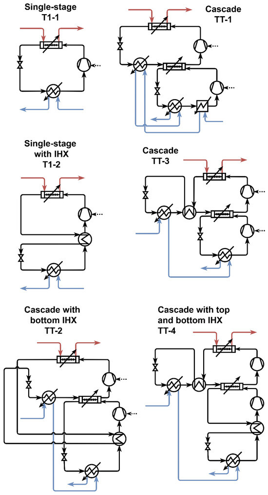
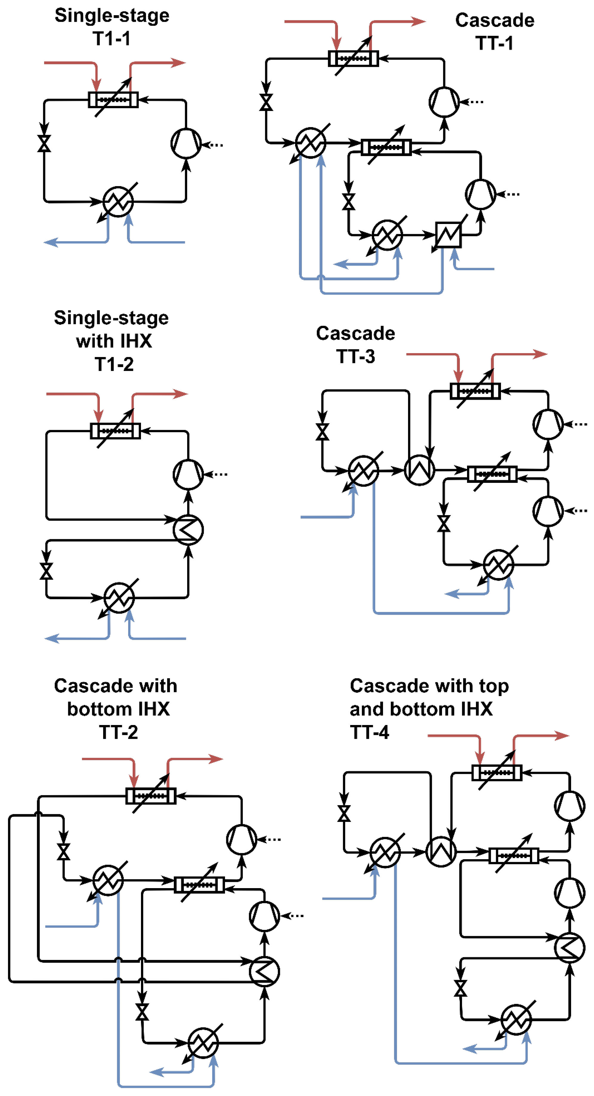
The baseline cycles, as shown in Figure 1, to which the cycles with expansion work recovery were compared against had been previously published in Kong et al. [17]. This section provides the conceptual rationale for the cycle modelling and approach. Interested readers are referred to Kong et al. [17] for specific modelling equations and parameters relating to the baseline results.
Figure 1.
Baseline transcritical–transcritical cascade cycles with various internal heat exchanger (IHX) positions with comparison to two single-stage cycles (T1-1 and T1-2). Refer to Kong et al. [17] for complete modelling results.
The analysis was based on a steady-state thermodynamic model of high-temperature transcritical–transcritical cascade CO2 heat pump cycles, specifically developed for process heating with a large temperature glide. A decentralised closed-cycle heat pump configuration was selected, where the heat pump supplied heat directly to the spray dryer air heating duty rather than producing steam for a central utility system. This configuration was selected because the sensible cooling profile of supercritical CO2 in the gas cooler is well matched to the large temperature glide required for spray dryer air heating.
CO2 was selected as the working fluid because of its low toxicity, low flammability, high volumetric heating capacity, and suitability for transcritical operation with low-temperature heat sources. The main disadvantage of CO2 is the high operating pressure required at high sink temperatures. Therefore, the maximum compressor discharge pressure was limited to 150 bar in the base analysis, which is approximately the upper pressure range of currently available CO2 compressor technologies for heat pump applications.
The representative spray drying case considered in this study required the process air to be heated from 15 °C to 200 °C. The source side of the heat pump was represented by a 40 °C water loop, corresponding to indirect recovery of low-temperature heat from the spray dryer exhaust or another low-grade waste heat source. The use of an intermediate water loop was included to reflect practical retrofit and hygiene considerations, where direct heat exchange between the refrigerant and process air may not be desirable. This was represented by a minimum approach temperature of 20 °C between the CO2 and the air stream in the high-temperature gas cooler. For CO2-to-CO2 heat exchange, including internal heat exchangers and cascade heat exchangers, the minimum approach temperature was set to 5 °C.
The base heat pump cycles were modelled using component-level mass and energy balances. The evaporator outlet was assumed to be saturated vapour unless the cycle configuration included superheating before compression. Compression was modelled as steady-state, adiabatic and non-isentropic, with an assumed compressor isentropic efficiency of 70%. An additional motor efficiency of 96% was included to account for heat dissipation, which was assumed to be lost from the cycle. Expansion valves were modelled as isenthalpic. Internal heat exchangers, gas coolers and cascade heat exchangers were modelled using energy balances with minimum approach temperature constraints to avoid temperature crossing.
In the baseline cycle model, the gas cooler outlet temperature and compressor pressure ratio were optimisation variables. The compressor discharge pressure was constrained to remain below the maximum pressure limit. For each target sink outlet temperature, the cycle was solved to maximise the heating coefficient of performance while satisfying the heat exchanger approach temperature constraints and thermodynamically valid refrigerant states. These baseline cycles provided the reference cases for assessing the effect of adding ejector- and expander-based expansion work recovery.
2.2. Ejector Modelling
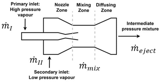
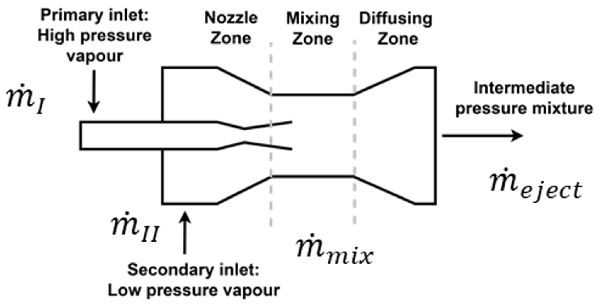
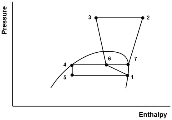
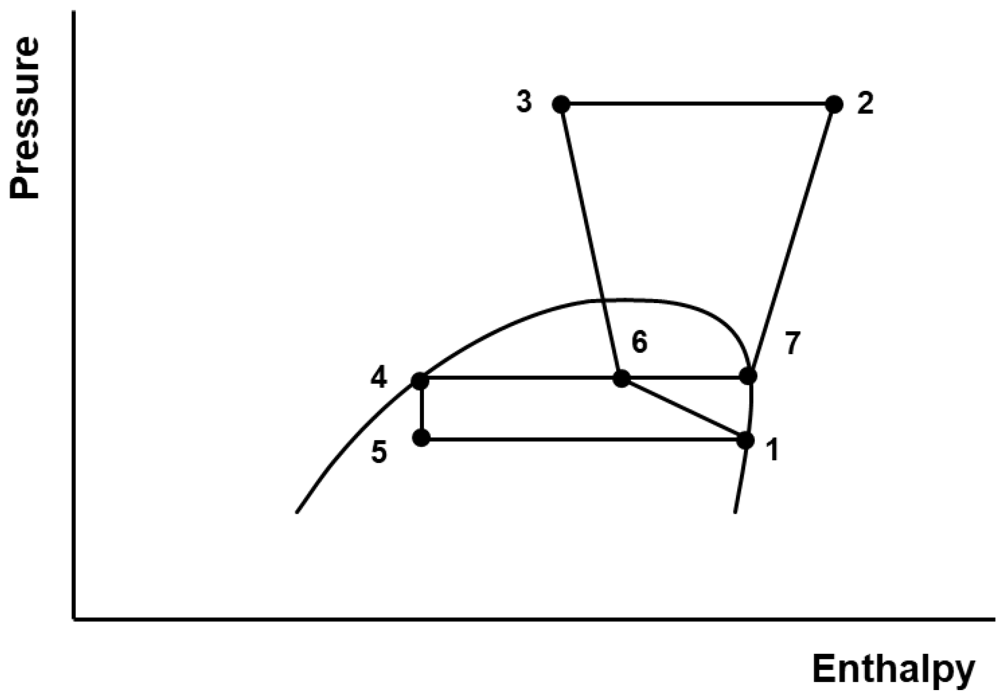
In the ejector cycles, the ejector was modelled as a device that used a high-pressure primary flow to entrain and compress a low-pressure secondary flow, producing an intermediate-pressure mixture (Figure 2 and Figure 3). In a heat pump cycle, the high-pressure vapour, referred to as the primary flow (I), is typically the refrigerant vapour exiting the gas cooler or further subcooled by an IHX (hot side). The low-pressure vapour, or secondary flow (), is the low-pressure refrigerant vapour that exits the evaporator. As the primary flow enters the ejector, the fluid undergoes expansion, converting pressure energy into kinetic energy. The high-velocity, low-pressure flow characteristic of the primary flow causes a low-pressure zone that draws the secondary flow into the ejector. The two flows mix turbulently in the mixing zone, and the resulting mixture enters the diffusing zone, where the velocity decreases and the pressure increases. An intermediate-pressure flow exits the ejector, which has a lower pressure than the primary flow but a higher pressure than the secondary flow. The intermediate-pressure outlet flow is often two-phase, which is then separated into vapour and liquid streams. The vapour is compressed, either directly or after further heating using an IHX (cold side). The increased pressure at the suction inlet, in comparison to the evaporator outlet, decreases the amount of compression work required. The liquid portion from the ejector, which does not go to the compressor, is expanded and then passes to the evaporator.
Figure 2.
Ejector structure with three different flow regimes. Adapted from Adamson et al. [7].
Figure 3.
P–h diagram of a simple ejector cycle T1e-1 with state points: (1) evaporator out, (2) compressor out, (3) gas cooler out, (4) ejector out, liquid portion/expansion valve in, (5) expansion valve out, (6) ejector outlet and (7) ejector out, vapour portion/compressor in.
The method for modelling the ejector followed the constant-pressure mixing model, which was validated for transcritical CO2 ejectors by You et al. [25]. A nozzle isentropic efficiency () of 80% was assumed to calculate the enthalpies () and the velocities () of the primary and secondary flows, respectively, at the outlet of the nozzle zone using Equations (1) and (2), consistent with Zhu et al. [41]. Between the inlet and the outlet, a pressure drop occurs as a result of frictional losses. The magnitude of the pressure drop varies depending on the operational parameters. As the proposed cycles had not yet been physically developed, a pressure drop of 0.03 MPa was adopted as a representative modelling assumption from prior transcritical CO2 ejector work [42]. This value was not validated for the present high-temperature cascade duty and is treated as a model limitation.
The entrainment ratio () is defined as the ratio between the mass flows of the secondary and primary flows (Equation (3)), which can be used to calculate the velocity of the combined flow () in the mixing zone (Equation (4)).
Using the velocity of the mixture and the conservation of energy principle, the specific enthalpy of the mixture () can be calculated using Equation (5).
The enthalpy at the ejector outlet (), i.e., the actual specific enthalpy of the mixed fluid out of the diffusing zone, was obtained using an energy balance between the primary and secondary flow inlets (Equation (6)). Where it was not possible to provide an enthalpy for the primary inlet (), the quality of the mixed flow at the exit of the ejector () was calculated using Equation (7) with an estimated initial value for entrainment ratio (). A solver was used to minimise the difference between the quality of the intermediate pressure flow () from Equation (7) and the value for quality () calculated from Equation (8).
To determine the value of the intermediate pressure flow exiting the ejector () for Equation (8), the isentropic enthalpy at the outlet of the ejector () was calculated using an assumed isentropic efficiency value of 80% for the diffuser section (), as shown in Equation (9). Then, the ejector outlet pressure is a function of the ideal outlet enthalpy and the entropy of the mixture (), as shown in Equation (10).
Finally, the Pressure Lift Ratio (PLR) for the ejector is given by Equation (11):
2.3. Expander Modelling
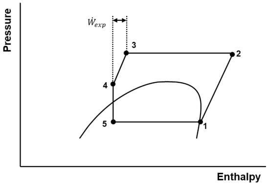
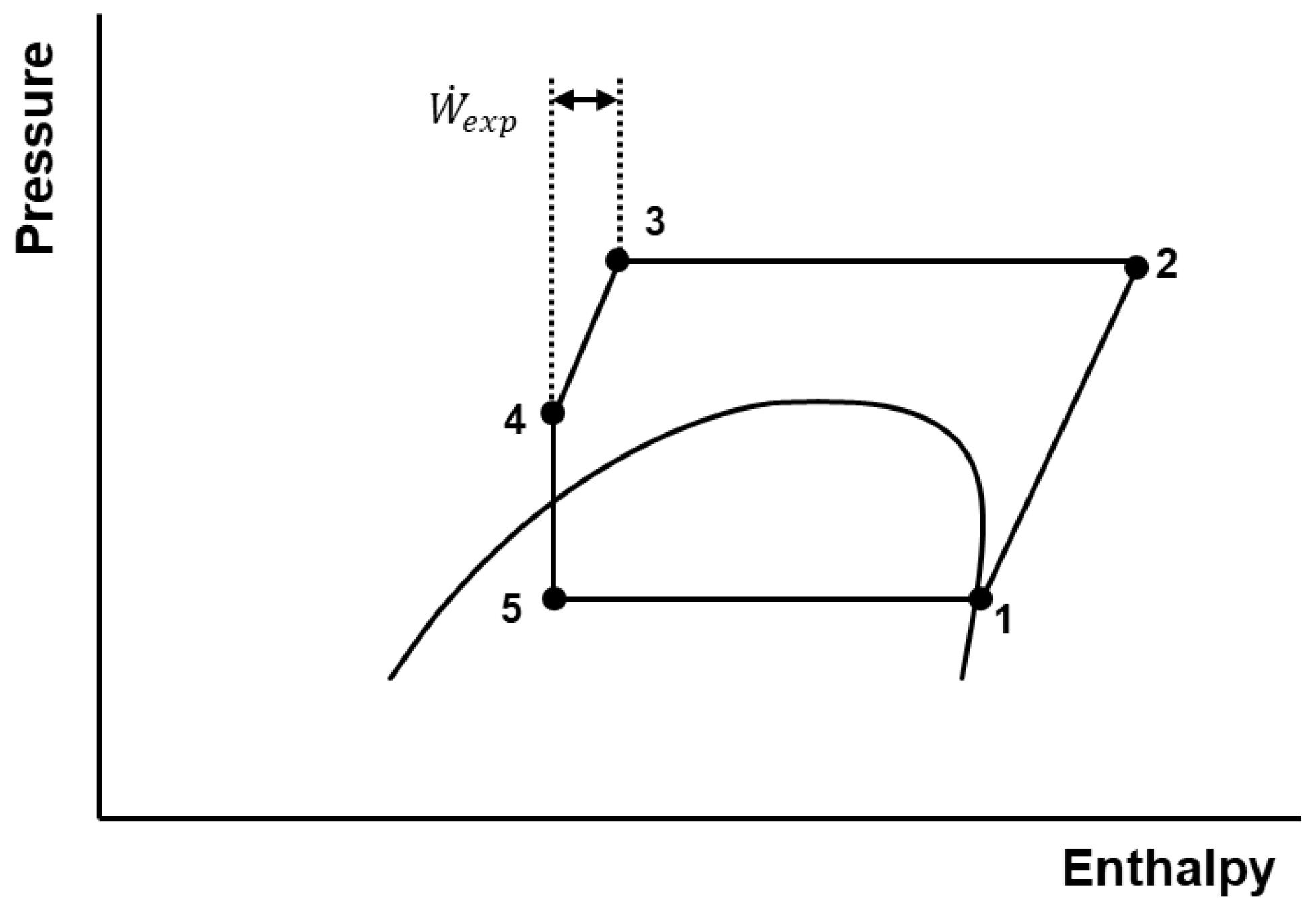
Expanders work by converting pressure energy into shaft work, either through a turbine or volumetric expander, such as a piston expander. In heat pump cycles, expanders often act in place of or in conjunction with an expansion valve, and the shaft work generated is used to provide power to the compressor shaft (often referred to as bootstrapping), reducing the overall work input for the heat pump, as illustrated in Figure 4. To model the expander, the isentropic relations and an assumed isentropic efficiency of 70% were used [43], as shown in Equation (12).
Figure 4.
P–h diagram of a simple expander cycle TX-1 with state points: (1) evaporator out, (2) compressor out, (3) gas cooler out, (4) expander out, and (5) expansion valve out.
Some expanders can handle two-phase flow, but it is preferable to operate away from the two-phase region due to mechanical limitations. To determine the outlet pressure from the expander, the pressure ratio was set as an optimisation variable, such that the fluid exited the expander as a liquid or supercritical phase, to determine the actual enthalpy at the outlet of the expander (), consistent with the method of Wolscht et al. [44]. The calculated value of isentropic efficiency was constrained to be equal to the assumed value. In some cases where the optimum pressure approached the critical point, a constraint was set to keep the fluid in the supercritical region. The remaining expansion required to reach the evaporation pressure was completed with an isenthalpic expansion valve.
Expanders are capital intensive devices, and cost estimations are not readily available in the open literature at the operating conditions that are required for HTHPs. However, the break-even cost of an expander () can be estimated in comparison to the equivalent original cycle concept (). To determine this cost, the electricity savings per kW of delivered heat () was first calculated from the cycle COPs (Equation (13)).
The annual electricity savings () could then be calculated using Equation (14). The annual operating hours (t) was assumed to be 6000 h per year at an electricity price () of 20 EUR/GJ.
Over an assumed lifetime () of 15 years for the heat pump system, the break-even cost (), below which the expander must cost to be economically favourable under the stated assumptions, can be calculated. The calculation assumed the same maintenance cost.
2.4. Cycle Concepts
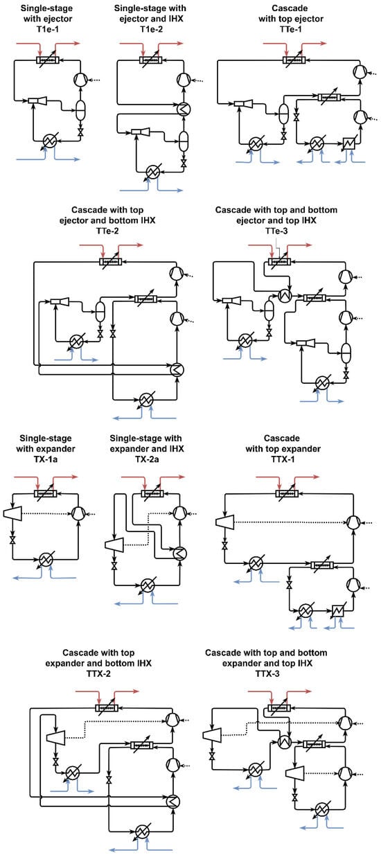
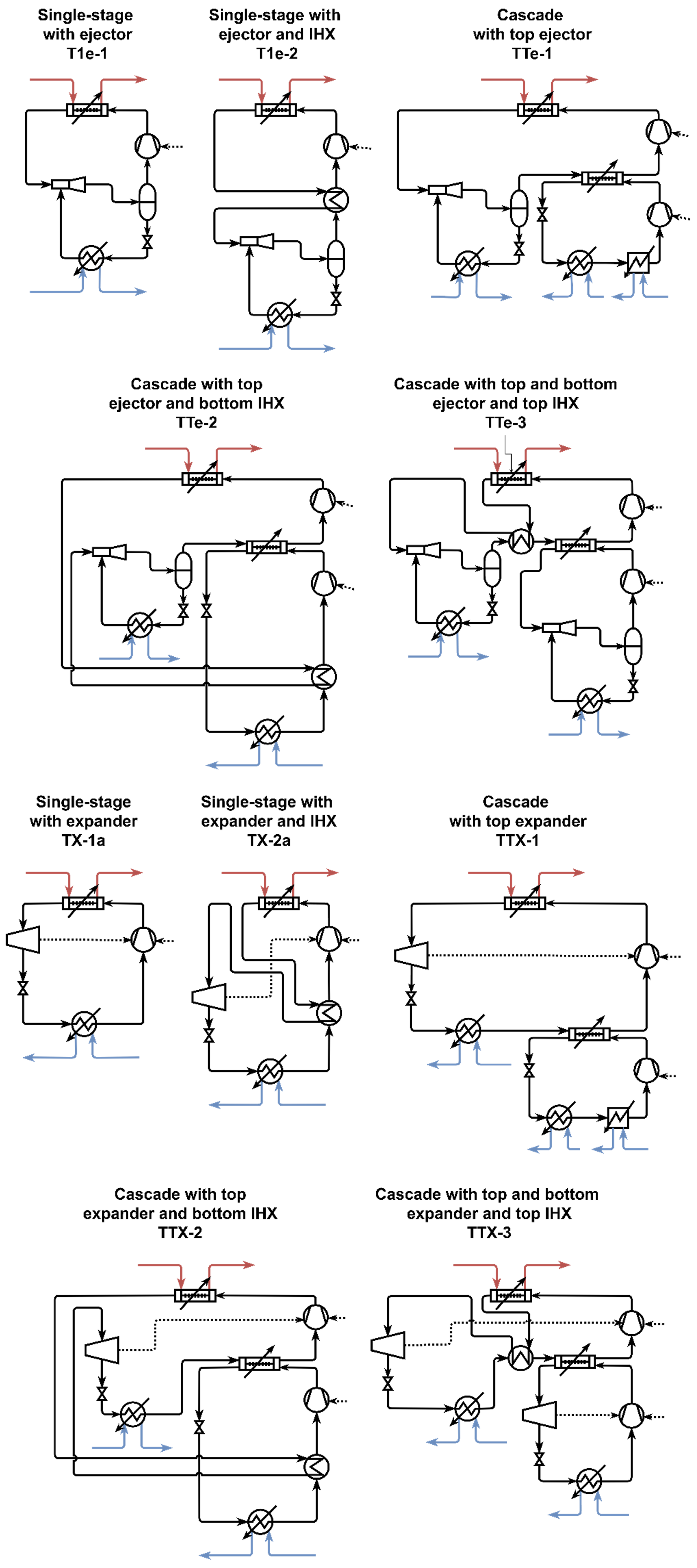
The ejector (e) and expander cycles (X) modelled in this study are shown in Figure 5. All cycles were variations of the baseline models (TT-1, TT-2, TT-3, and TT-4) analysed by Kong et al. [17]. The single-stage ejector and expander cycles (T1e-1, T1e-2, TX-1a and TX-2a) were modelled for comparative purposes. However, the main focus of the modelling was on the cascade cycles that had high exergy destruction during expansion, to determine whether integrating an ejector or an expander could increase the performance significantly in comparison to the best-performing baseline cycle, TT-4. No TT-4 recovery variant was constructed; TT-4 was used only as the best-performing baseline benchmark.
Figure 5.
Ejector and expander cycle concepts.
Model TT-1 had the highest exergy destruction during expansion in the top cycle, 9.0 kJ/kgsink. Models TTe-1 and TTX-1 were variations of TT-1 with expansion work recovery replacing the isenthalpic expansion valve in the top cycle. Model TT-2 had the most comparable COP to TT-4 for the spray dryer air heating conditions, despite having more than double the exergy destruction in the top-cycle expansion valve (6.1 kJ/kgsink). Models TTe-2 and TTX-2 had expansion work recovery integrated in the top cycle after the IHX, which exchanged heat from the top-cycle gas cooler outlet to the bottom-cycle compressor inlet.
In these cycles, the exergy destruction during expansion for the bottom cycle was comparable to the best-performing cycle (TT-4); therefore, expansion work recovery was only integrated in the top cycles. However, Model TT-3 exhibited large amounts of exergy destruction in both the top and bottom cycles. As a result, the variations of TT-3, i.e., TTe-3 and TTX-3, had expansion work recovery integrated in both the top and bottom cycles.
2.5. Thermodynamic Performance Evaluation
The cycles were modelled for the spray drying case study using a heat source temperature of 40 °C and process air heating from 15 °C to 200 °C. The main metrics used to evaluate the performance of the ejector and expander cycles were heating coefficient of performance (COP), maximum achievable sink temperature, and component-level exergy destruction. For the baseline and ejector cycles, the net work input was calculated from the compressor work (since there was no work recovery). For the expander cycles, the net work input was calculated as the compressor work less the recovered expander work.
For the spray drying case, the evaporation temperatures were treated as optimisation variables, and the compressor discharge pressure was fixed at 150 bar unless otherwise stated. The optimisation objective was to maximise the heating COP while satisfying the target sink outlet temperature, heat exchanger minimum approach temperature constraints, and thermodynamically valid refrigerant states. For ejector cycles, the entrainment ratio was treated as an optimisation variable. For expander cycles, the expander outlet pressure ratio was optimised while constraining the outlet state to avoid two-phase operation where possible; any remaining expansion to the evaporator pressure was completed using an isenthalpic expansion valve.
The models were implemented in Microsoft Excel (v16.0) using VBA and solved using Solver add-in (GRG Nonlinear). Each optimisation used a single cold start with pressures at 15 MPa, and convergence was accepted when changes trended below 0.0001.
The exergy destruction (kW) across the cycle components was also calculated to determine where the inefficiencies occurred within the cycle. In the heat exchangers, the exergy destruction was the difference between the exergy transferred for each of the streams (Equation (16)).
The thermo-mechanical exergy for the stream () was defined by the specific enthalpy and specific entropy of the stream referenced to a dead state condition of °C and kPa (Equation (17)).
Lastly, the exergetic efficiency () was calculated from the change in exergy of the sink and source and the total compressor electric power consumption using Equation (18) [45].
3. Results
The objective of the analysis was to assess selected ejector- and expander-enhanced transcritical CO2 heat pump cycles against their corresponding baseline configurations, with TT-4 retained as an external performance benchmark. As ejectors and expanders recover part of the expansion work, the compression work required for the heat pump is theoretically decreased.
Each expansion device introduces different practical and thermodynamic trade-offs. Ejectors are relatively low cost and have no moving parts, but their performance is sensitive to operating conditions, and part-load operation can be challenging. This is less of an issue for the milk powder spray drying case study, where the set-point conditions tend to be steady when operating, but it may be significant for other applications. Expanders generally recover more work, but they are more costly, require additional maintenance, and increase system complexity. Therefore, a significant increase in COP compared with the baseline cycles would be required to justify the integration of an expansion work recovery device.
3.1. Maximum Sink Temperatures
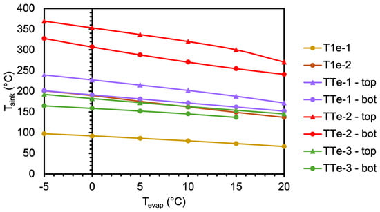
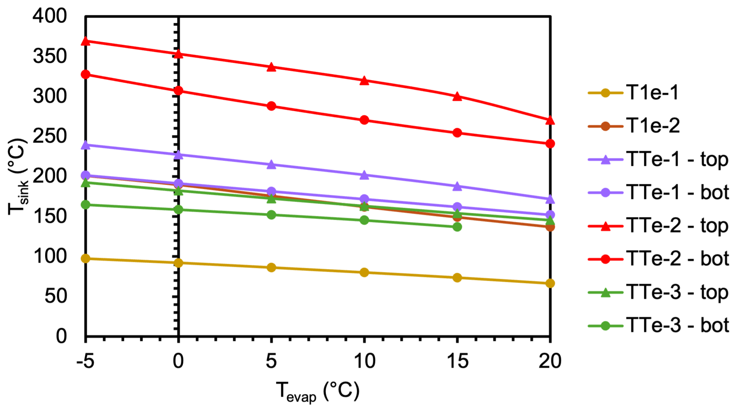
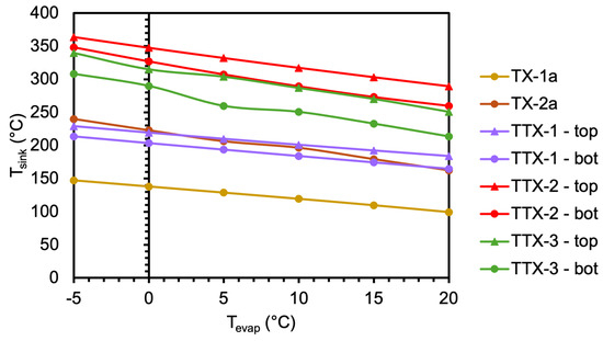
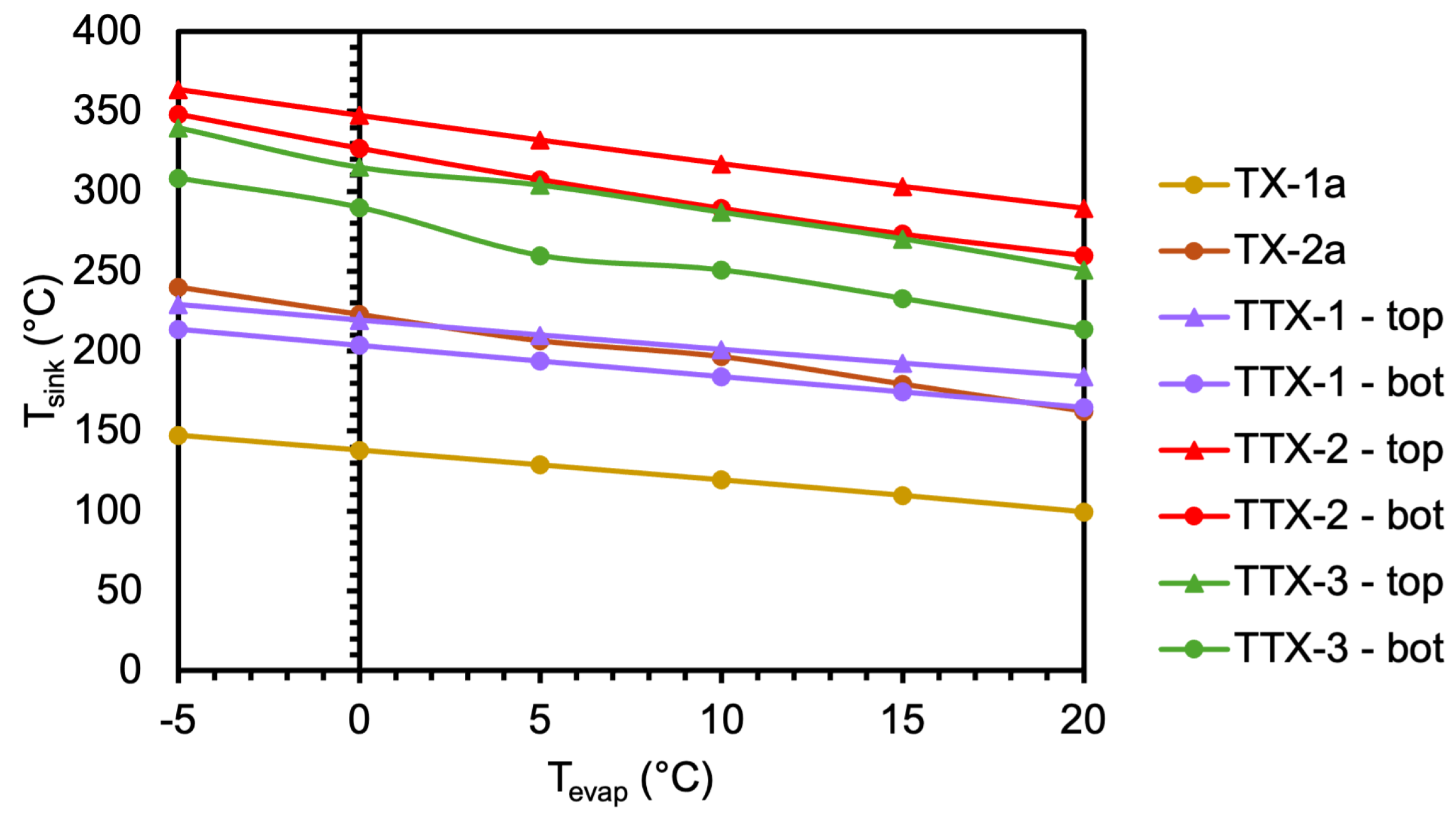
In the initial modelling stages, it was found that the specified evaporation temperatures for the transcritical cascade cycles were not suitable for all target conditions. For cycle TTe-3, the selected top-cycle evaporation temperature of 20 °C resulted in an ejector outlet pressure in the supercritical region. While it is possible to use a supercritical CO2 (sCO2) ejector, additional complexity is introduced because sCO2 ejectors are far less established than two-phase ejectors, and analytical frameworks for modelling sCO2 ejectors are limited in the open literature [25]. To avoid this, a simpler approach was adopted by lowering the evaporation temperature to increase the maximum achievable sink temperature. However, this is a trade-off, as lowering the evaporation temperature can result in a greater pressure ratio across the compressor, increasing the work input and the thermodynamic strain on the system. Furthermore, many cycles were unable to reach the target sink temperature of 200 °C under the maximum pressure constraint at the specified evaporation temperatures. Consequently, the evaporation temperature was varied to determine the maximum sink temperature for the ejector cycles (Figure 6) and expander cycles (Figure 7).
Figure 6.
Maximum sink temperature at varying evaporation temperatures—ejector cycles.
Figure 7.
Maximum sink temperature at varying evaporation temperatures—expander cycles.
The equivalent ejector and expander cycles to the single-stage cycle T1-1 were T1e-1 and TX-1a, respectively. The inclusion of an ejector in T1e-1 reduced the maximum sink temperature for the same evaporation temperature of 10 °C, whereas the inclusion of an expander in TX-1a had little effect on the maximum sink temperature compared with T1-1. A similar trend was observed for T1e-2 and TX-2a, which are the equivalent cycles to the single-stage cycle with an IHX, T1-2. T1e-2 was able to achieve the target sink temperature at an evaporation temperature of −5 °C, and TX-2a was able to achieve the target sink temperature at evaporation temperatures below 10 °C. For all cascade cycles, the top-cycle evaporation temperature had a greater influence on the maximum sink temperature than the bottom-cycle evaporation temperature. The equivalent cycles for TT-2 achieved the highest maximum sink temperatures for both the ejector (TTe-2) and expander (TTX-2) variants. The maximum sink temperature was severely limited by the addition of an ejector in TTe-3 compared with TT-3 and TTX-3. The maximum sink temperatures for TTX-1 and TTe-1 were similar across the range of evaporation temperatures.
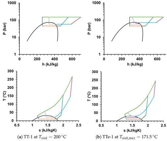
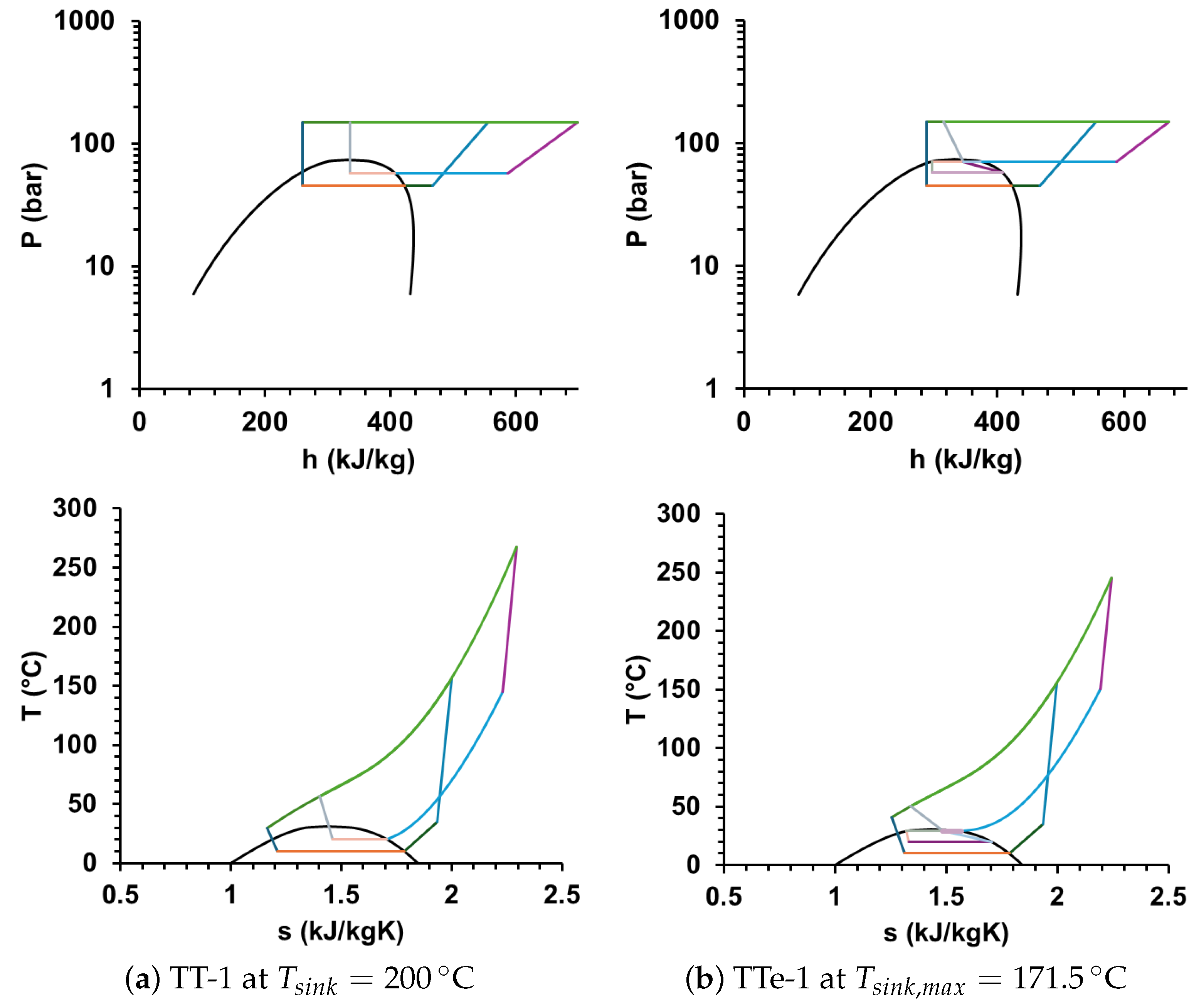
An example of the effect of the ejector on the maximum sink temperature can be seen by comparing cycles TT-1 and TTe-1, as shown in Figure 8. In these diagrams, the evaporation temperatures are held constant at 10 °C for the bottom cycle and 20 °C for the top cycle. Under these conditions, TT-1 is able to achieve the target sink temperature of 200 °C; however, TTe-1 can only achieve a maximum sink temperature of 171.5 °C as a result of the lower pressure ratio across the compressor. It is possible to increase the sink temperature, but this would require increasing the pressure ratio or reducing the minimum approach temperature in the gas cooler.
Figure 8.
P–h and T–s diagrams for (a) TT-1 and (b) TTe-1 for = 10 °C and = 20 °C.
3.2. Cycle COPs and Spray Drying Case Study
At the same sink temperature of 171.5 °C, TT-1 still performed better than TTe-1. One reason for this was a significant decrease in the performance of the bottom cycle, despite the ejector increasing the performance of the top cycle. In the top cycle, the compressor work requirement decreased from 45.88 to 38.92 kJ/kgsink, which increased the COP of the top cycle from 3.45 to 4.06 (Table 1). However, the COP of the bottom cycle decreased from 3.21 to 2.90 because less heat was transferred in the cascade gas cooler. Additionally, the CO2 exited the gas coolers of both the top and bottom cycles at higher temperatures, which reduced the ability to leverage the higher heat capacity of CO2 at temperatures closer to the critical point (~31 °C). This also increased exergy destruction during expansion due to the higher temperatures in the bottom cycle. A similar effect on the COPs was observed between the baseline cycles and the ejector cycles for the TT-2 and TT-3 variants.
Table 1.
COPs of cycles TT-1 and TTe-1 at a sink temperature of 171.5 °C.
The evaporation temperatures were set as additional optimisation variables for the spray drying case study, and the discharge pressure was fixed at 150 bar. The optimisation maximised the cycle COP for a target air temperature of 200 °C. In the ejector cycles, the entrainment ratios were also optimisation variables, with the constraint that the estimated vapour fraction at the exit of the ejector was equal to the calculated vapour fraction. The estimated vapour fraction was initialised using the entrainment ratio, as shown in Equations (7) and (8) (Section 2.2). The resultant entrainment ratios and pressure lift ratios for the ejectors are given in Table 2. Cycle T1e-1 was excluded because the cycle was unable to achieve the target sink temperature at the specified conditions, despite lowering the evaporation temperature. For all remaining ejector cycles, the entrainment ratios varied between 0.38 and 0.71. Palacz et al. [46] noted that the entrainment ratio of two-phase CO2 ejectors for refrigeration cycles tended not to exceed 0.5. However, data from You et al. [25] showed that a higher motive pressure of up to 120 bar increased the entrainment ratio to approximately 0.7. The pressure lift ratios varied between 1.18 and 1.51, which resulted in pressure lifts of approximately 10 to 15 bar. This was within the typical 2–16 bar lift noted by Palacz et al. [46].
Table 2.
Entrainment and pressure lift ratios for the ejector cycles.
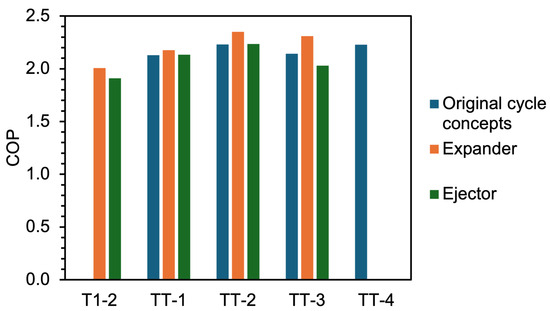
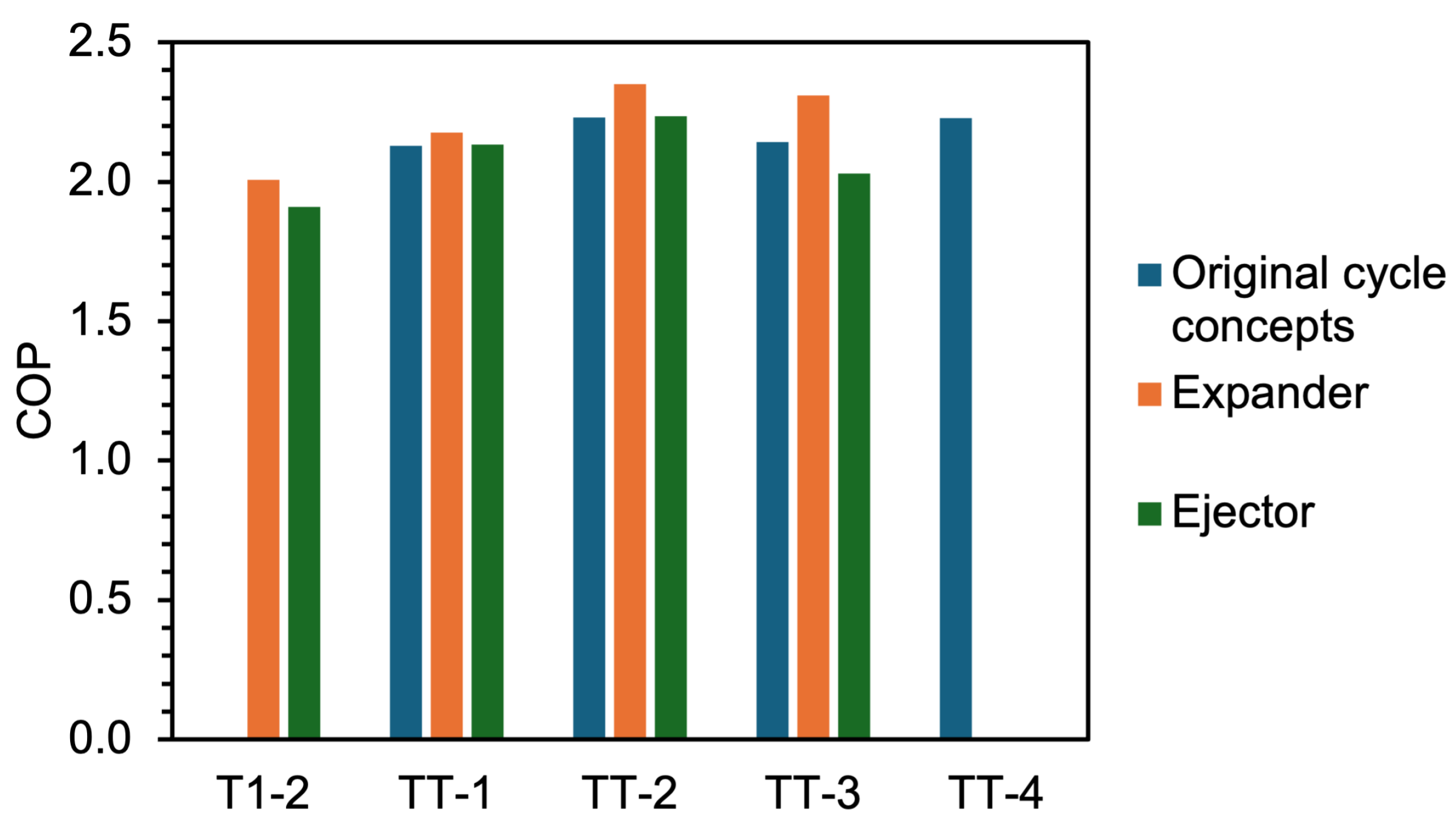
A comparison of the COPs achieved by the ejector and expander cycles with the equivalent baseline cycle concepts is given in Figure 9. It should be noted that the COPs of the baseline cycles may vary slightly from the previously reported values by Kong et al. [17], as the evaporation temperatures were treated as optimisation variables in the present analysis rather than fixed values. The COP of the best-performing baseline cycle, TT-4, is also given for comparison. No TT-4 recovery variant was constructed; TT-4 was used only as the best-performing baseline benchmark. The recovery devices were applied to configurations with comparatively high expansion exergy destruction and, where possible, no more components than TT-4.
Figure 9.
Comparison of the COPs achieved by the expansion work recovery cycles.
With the optimised evaporation temperatures, TT-2 and the external benchmark TT-4 each achieved a COP of 2.23 at 150 bar for the investigated duty. This benchmark comparison was not an evaluation of a TT-4 recovery variant. TT-2 achieved the same performance at that operating point despite having one less heat exchanger. However, the broader baseline analysis reported by Kong et al. [17] should also be considered, because TT-4 consistently outperformed TT-2 over varying conditions. In that analysis, the capital cost estimates for TT-2 and TT-4 were relatively similar at 124,295 EUR and 125,489 EUR, respectively.
For all expander cycles, the COP was increased through the use of an expander. The most notable effect was between TT-3 and TTX-3; however, this is likely because TTX-3 had two expanders whereas the rest of the cycles only had one. For expander cycles with one expander, the most notable increase was in TTX-2. TTX-2 achieved a COP of 2.35, 5.4% above its corresponding TT-2 baseline. TT-2 and the external benchmark TT-4 each achieved a COP of 2.23 at 150 bar for the investigated duty. The comparison with TT-4 was a benchmark comparison, not an evaluation of a TT-4 recovery variant. Capital cost estimations for CO2 expanders in a similar operating range were not readily available in the open literature; therefore, it was difficult to determine whether the increased COP for TTX-2 was significant enough to warrant integration. However, a break-even cost for the expander could be estimated (Table 3).
Table 3.
Expander break-even cost calculation breakdown.
The attributable effect of adding the expander, and therefore its break-even cost, was assessed through the like-for-like comparison of TTX-2 with its corresponding TT-2 baseline. The amount of electricity used per kW of delivered heat was taken as the inverse of the COP, resulting in 0.43 kWelec/kWth for TTX-2 and 0.45 kWelec/kWth for TT-2—an electricity saving of 0.02 kWelec/kWth. For an annual operating time of 6000 h/year and a heat pump lifetime of 15 years, the break-even capital cost for the expander was 149.3 EUR/kWth of installed heating capacity.
The value of 149.3 EUR/kWth was therefore an upper-bound screening estimate. Under the same undiscounted 15-year assumptions, each additional 1 EUR/(kWth·year) of annual maintenance attributable to the expander reduced the break-even capital cost by 15 EUR/kWth; illustrative additional maintenance costs of 2 and 5 EUR/(kWth·year) reduced the break-even value to 119.3 and 74.3 EUR/kWth, respectively. This estimate applies only to the investigated spray dryer duty and stated economic assumptions.
Another challenge for the expander cycles is that, in many cases, the optimal expander outlet pressures were very close to the critical point (Table 4). Near the critical point, small changes in temperature or pressure can cause very large changes in density, compressibility and heat capacity [47]. This makes the mechanical design of the expander difficult because the flow conditions vary rapidly. It is unclear exactly how this would affect the mechanical and operational limitations of the expander. Alternatively, expanding to a smaller pressure ratio to remain further from the critical point could be considered; however, this would decrease the COP improvement and therefore reduce the break-even cost of the expander.
Table 4.
Expander outlet pressures for cycles TX-2a, TTX-1, TTX-2 and TTX-3.
The CO2 expander in this study was modelled using an assumed isentropic efficiency of 70% to represent a more realistic, non-ideal expansion. Nevertheless, this approach still simplifies the analysis and lumps all of the irreversibilities present in actual devices like mechanical losses, leakage, friction, and turbulence. These limitations are particularly prevalent in supercritical CO2, where the properties vary sharply near the critical point. Additional factors, including heat transfer between the working fluid and the expander walls, potential condensation, and mechanical constraints due to the high fluid density were also not considered. As a result, the model may overestimate system performance gains. Future work should incorporate CFD modelling and experimental validation to improve confidence in the predicted expander performance.
3.3. Exergy Destruction
The ejector cycles were unable to achieve higher COPs than the baseline cycle concepts. T1-2 was unable to achieve the target sink temperature of 200 °C and was therefore excluded. T1e-2 achieved a COP of 1.91, which was lower than the COP of TX-2a at 2.01. Despite T1e-2 having lower exergy destruction during expansion (10.2 kJ/kgsink) than TX-2a (13.7 kJ/kgsink), the lower COP resulted from the greater pressure ratio required across the compressor to achieve the target sink temperature. The pressure ratio required to achieve the 200 °C sink outlet temperature was 4.7 in T1e-2, whereas TX-2a only required a pressure ratio of 3.7. The COPs of TTe-1 (2.13) and TTe-2 (2.23) were identical to those of their respective baseline configurations but remained below those achieved by the expander cycles (2.18 and 2.35, respectively). Conversely, TTe-3 demonstrated a lower COP (2.03) compared with both TT-3 (2.14) and TTX-3 (2.31).
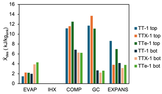
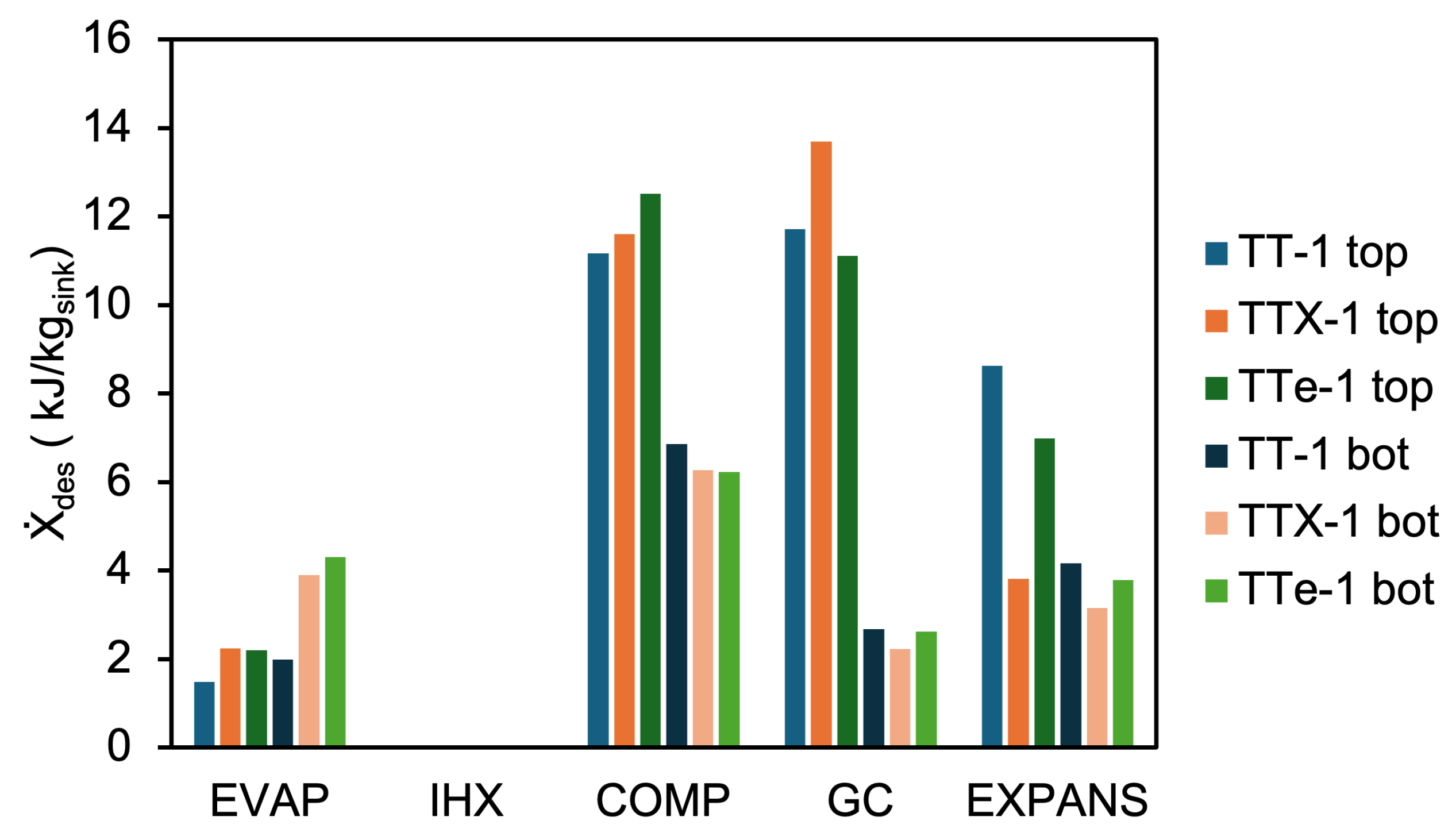
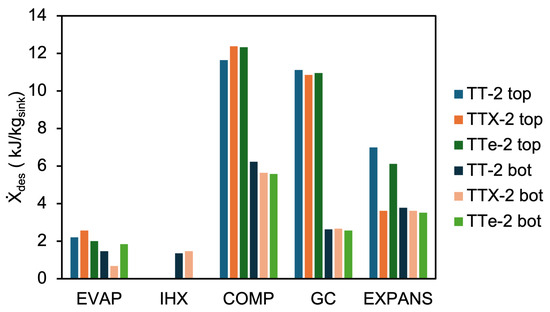
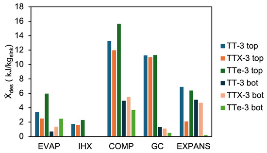
The exergy destruction in the components for the TT-1, TT-2 and TT-3 cycle variants is shown in Figure 10, Figure 11 and Figure 12. The “EXPANS” category includes the total exergy destruction related to expansion of the refrigerant from a valve, ejector, expander, or a combination of expansion devices. In the case of TTe-3, the top-cycle pressure ratio, which affects the cycle with most of the refrigerant mass flow, increased from 2.9 to 3.7, resulting in greater exergy destruction in the compressor (Figure 12). Consequently, the bottom-cycle pressure ratio decreased in comparison to TT-3 to compensate the top-cycle changes.
Figure 10.
Exergy destruction in the cycle components for TT-1 variants (no IHX present).
Figure 11.
Exergy destruction in the cycle components for TT-2 variants.
Figure 12.
Exergy destruction in the cycle components for TT-3 variants.
The changes in exergy destruction in TTe-1 and TTe-2 compared with TT-1 and TT-2 were more moderate, which was expected from the resulting COPs. The exergy destruction during expansion for TTe-1 decreased for both the top cycle (8.6 to 7.0 kJ/kgsink) and bottom cycle (4.2 to 3.8 kJ/kgsink) but increased in both evaporators, from 1.5 to 2.2 kJ/kgsink in the top cycle and from 2.0 to 4.3 kJ/kgsink in the bottom cycle (Figure 10). The exergy destruction during compression was reduced slightly from 2.7 to 2.6 kJ/kgsink in the bottom cycle for TTe-1, but this was negated by the slight increase in exergy destruction from 11.2 to 12.5 kJ/kgsink in the top-cycle compressor. Likewise, the exergy destruction during expansion was reduced slightly between TTe-2 (5.6 kJ/kgsink) and TT-2 (6.2 kJ/kgsink), but the compressor exergy destruction in the top-cycle compressor increased from 11.6 to 12.3 kJ/kgsink, and the bottom-cycle evaporator exergy destruction increased from 1.5 to 1.8 kJ/kgsink, as shown in Figure 11.
Compared to TT-1, the inclusion of an expander caused small increases in exergy destruction across most of the components (Figure 10). However, TTX-1 had significantly lower exergy destruction during expansion (7.0 kJ/kgsink total) compared to TT-1 (12.8 kJ/kgsink total). Decreases in exergy destruction were also observed in the bottom-cycle compressor by 0.6 kJ/kgsink and gas cooler by 0.5 kJ/kgsink. In TTX-2 (Figure 11), increases in exergy destruction (compared to TT-2) were observed in the evaporator (0.4 kJ/kgsink) and compressor (0.8 kJ/kgsink) of the top cycle, and the IHX (0.1 kJ/kgsink) and gas cooler (0.1 kJ/kgsink) of the bottom cycle. However, the exergy destruction for the remaining components decreased. As with the TT-1 variants, the most notable decrease in exergy destruction was during expansion, from 11.8 kJ/kgsink total for TT-2 to 7.2 kJ/kgsink total for TTX-2.
The difference between the expander and baseline cycle COPs were most notable for the TT-3 variants (Figure 12), with TT-3 having a COP of 2.14 and TTX-3 having a COP of 2.31 (Figure 9). Although the exergy destruction increased slightly for some of the bottom-cycle components, the exergy destruction across all top-cycle components decreased. The most significant decrease was the reduction in exergy destruction during expansion from 12.0 kJ/kgsink total in TT-3 to 6.8 kJ/kgsink total in TTX-3.
3.4. Compressor Discharge Pressures
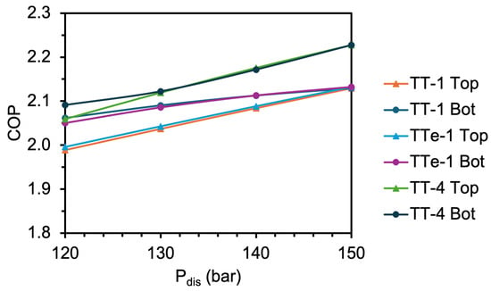
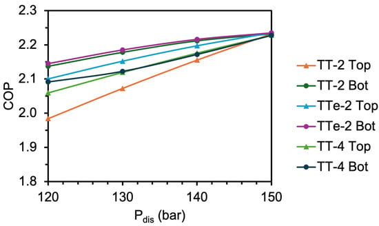
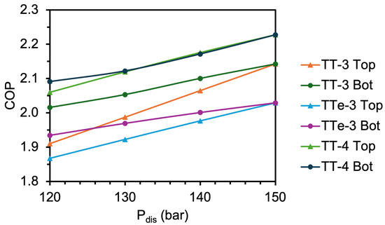
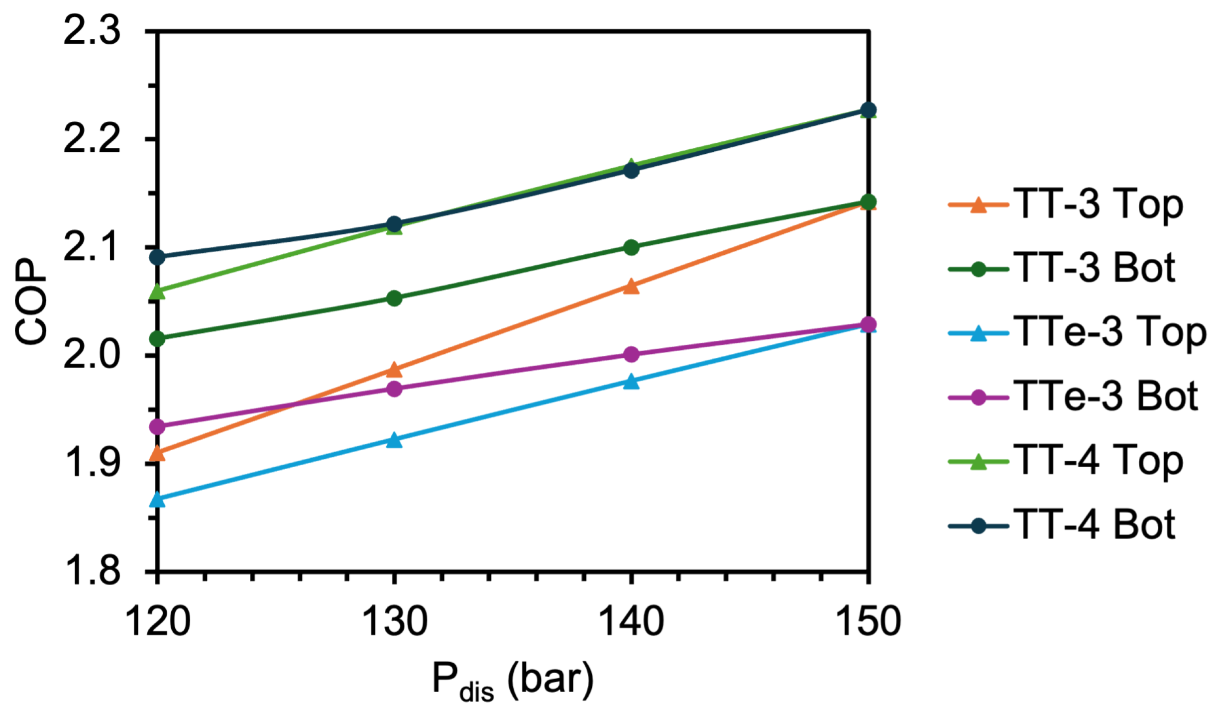
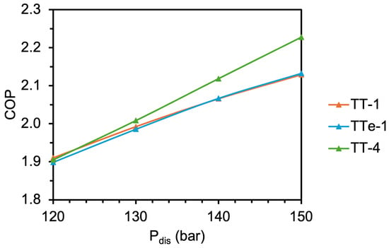
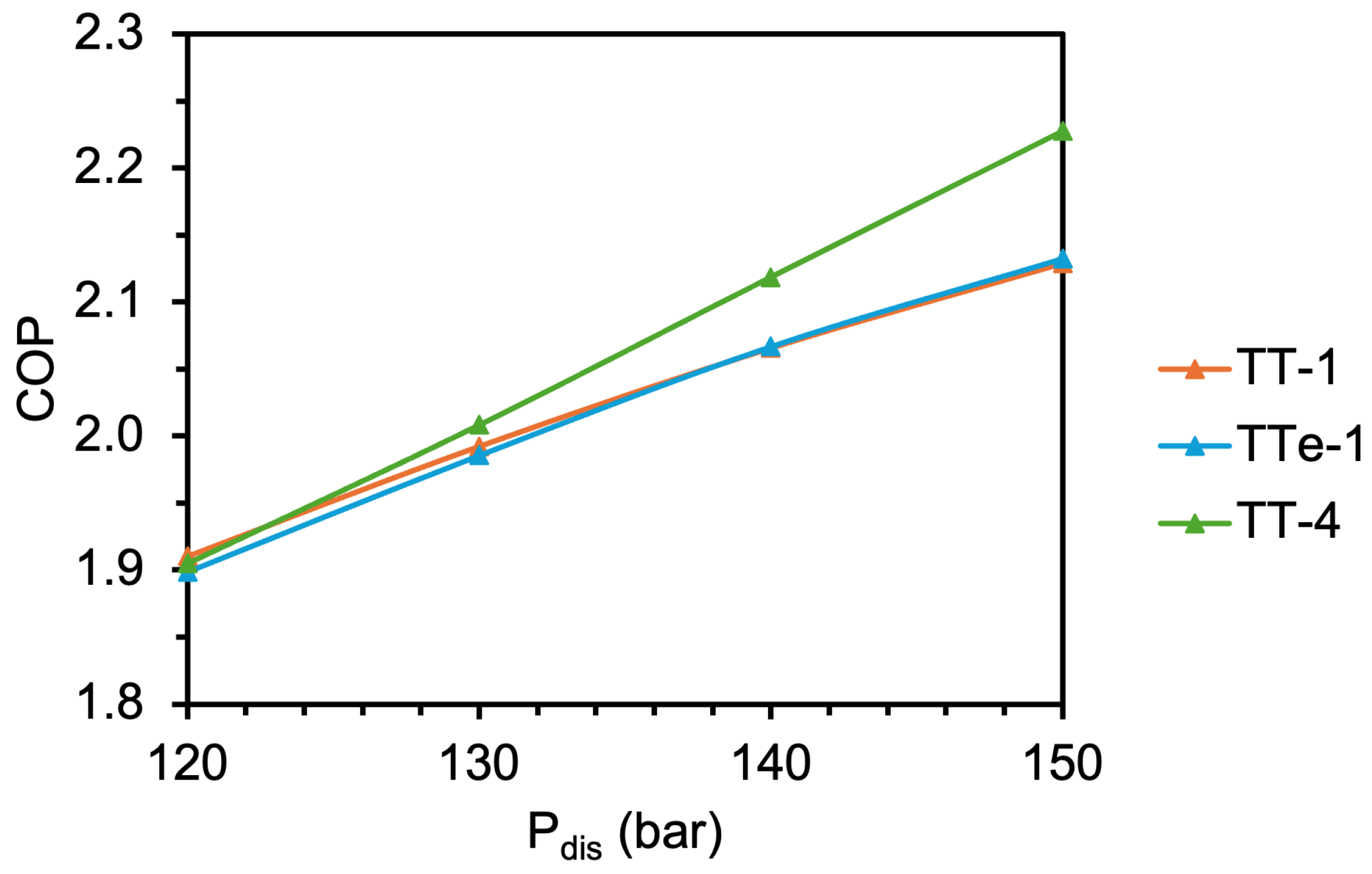
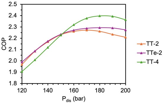
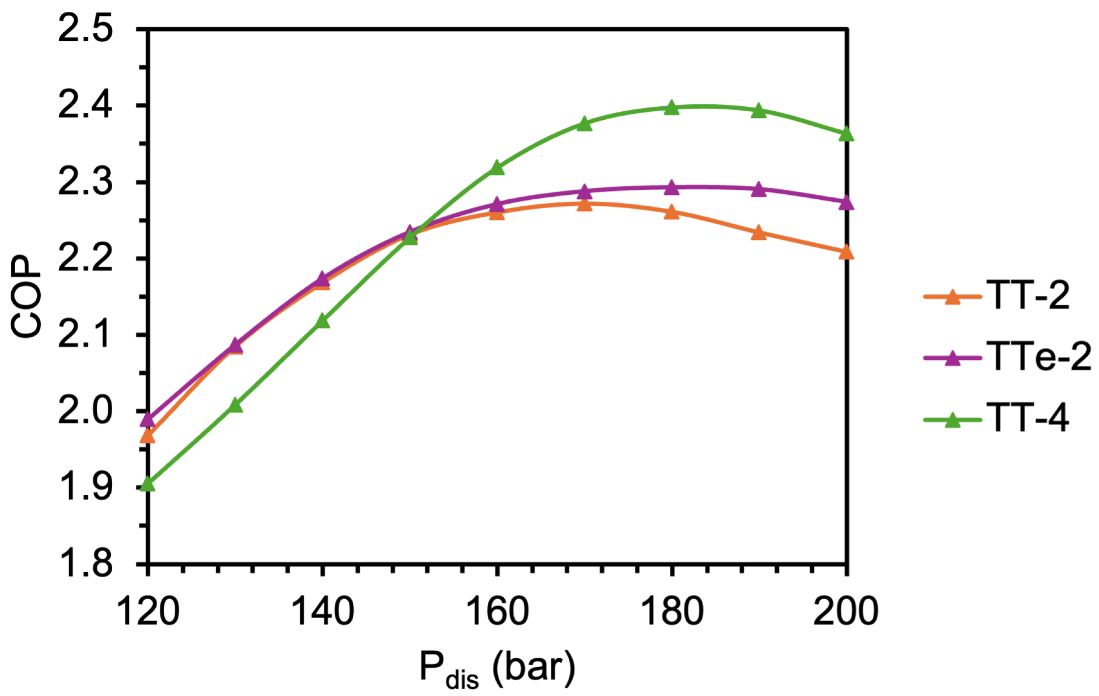
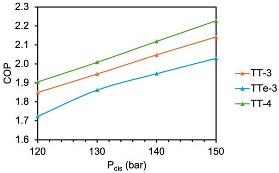
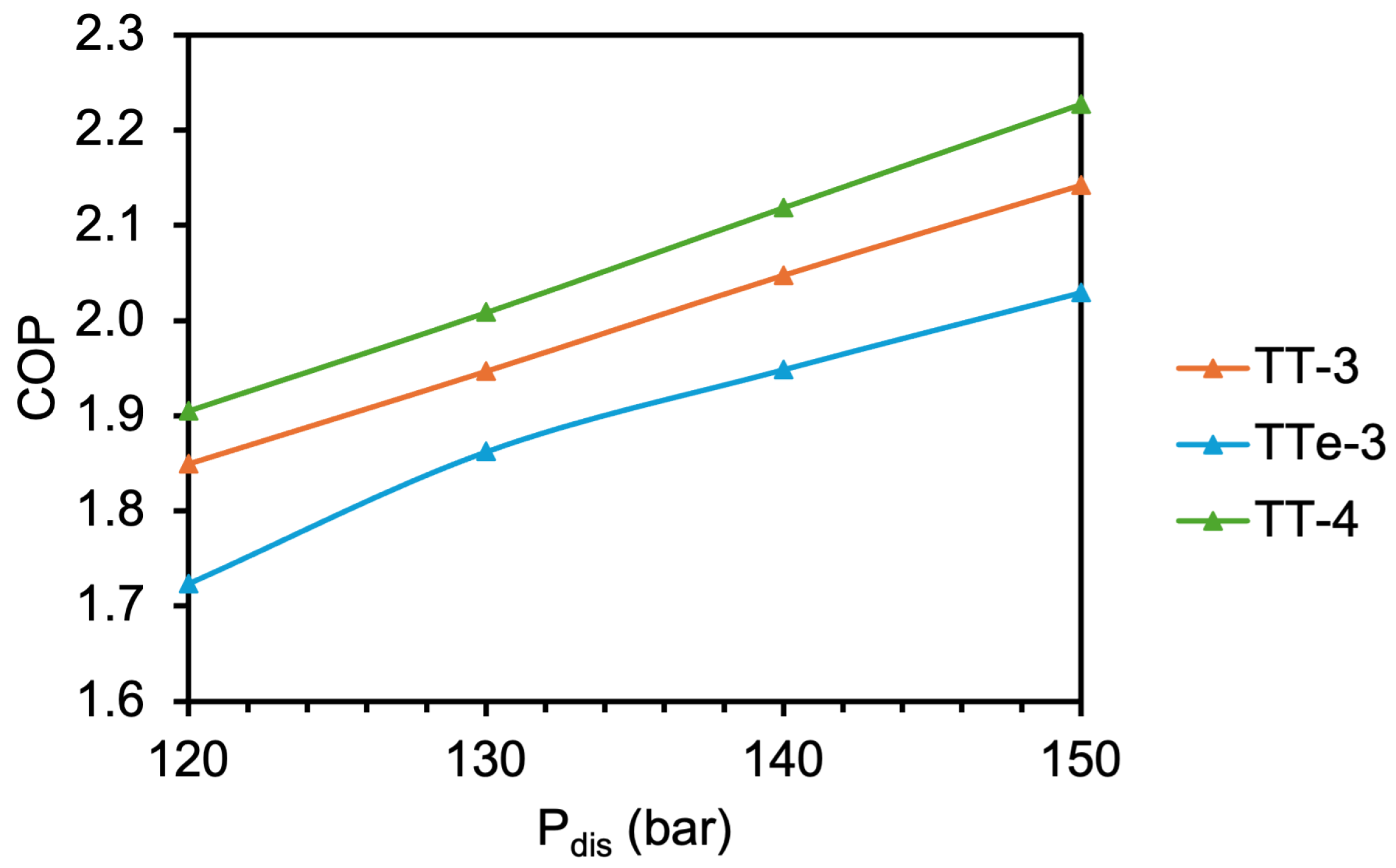
To simplify the optimisation in Section 3.1, Section 3.2 and Section 3.3, the discharge pressures of both cycles were kept constant at 150 bar for both the top and bottom cycles. The effect of varying discharge pressure on the COP was then analysed to determine whether the relative performance of the baseline and ejector cycles changed at lower pressure limits. Figure 13 shows the effect of varying the discharge pressure for TT-1 and TTe-1, with TT-4 also given for comparison. Figure 14 presents the results for TT-2 and TTe-2, and Figure 15 presents the results for TT-3 and TTe-3. In these figures, the discharge pressure was varied for either the top or bottom cycle, while the other cycle was kept constant at 150 bar. The discharge pressures were varied between 120 and 150 bar.
Figure 13.
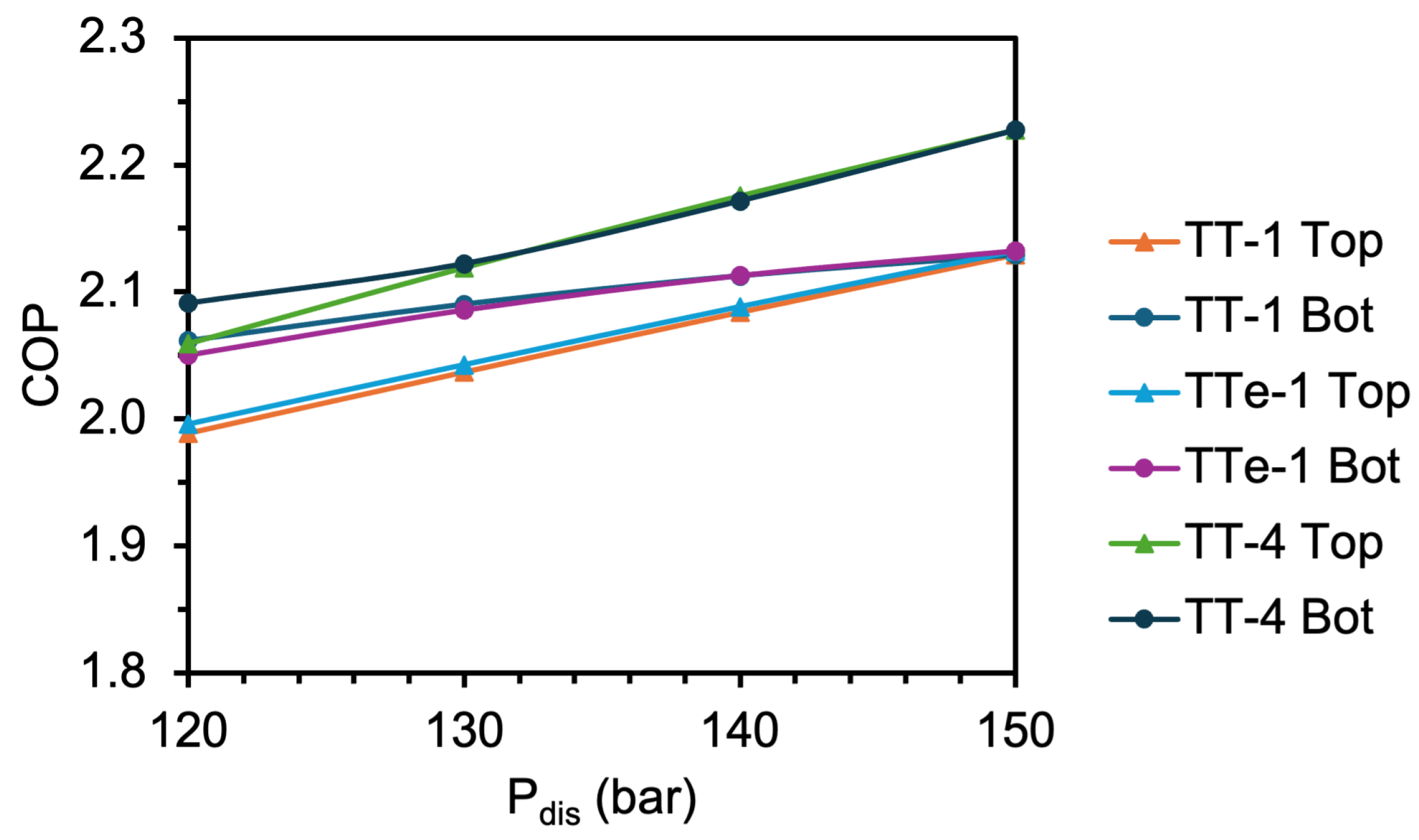
COPs of TT-1, TTe-1 and TT-4 at varying maximum pressures for one cycle/150 bar for the other cycle.
Figure 14.
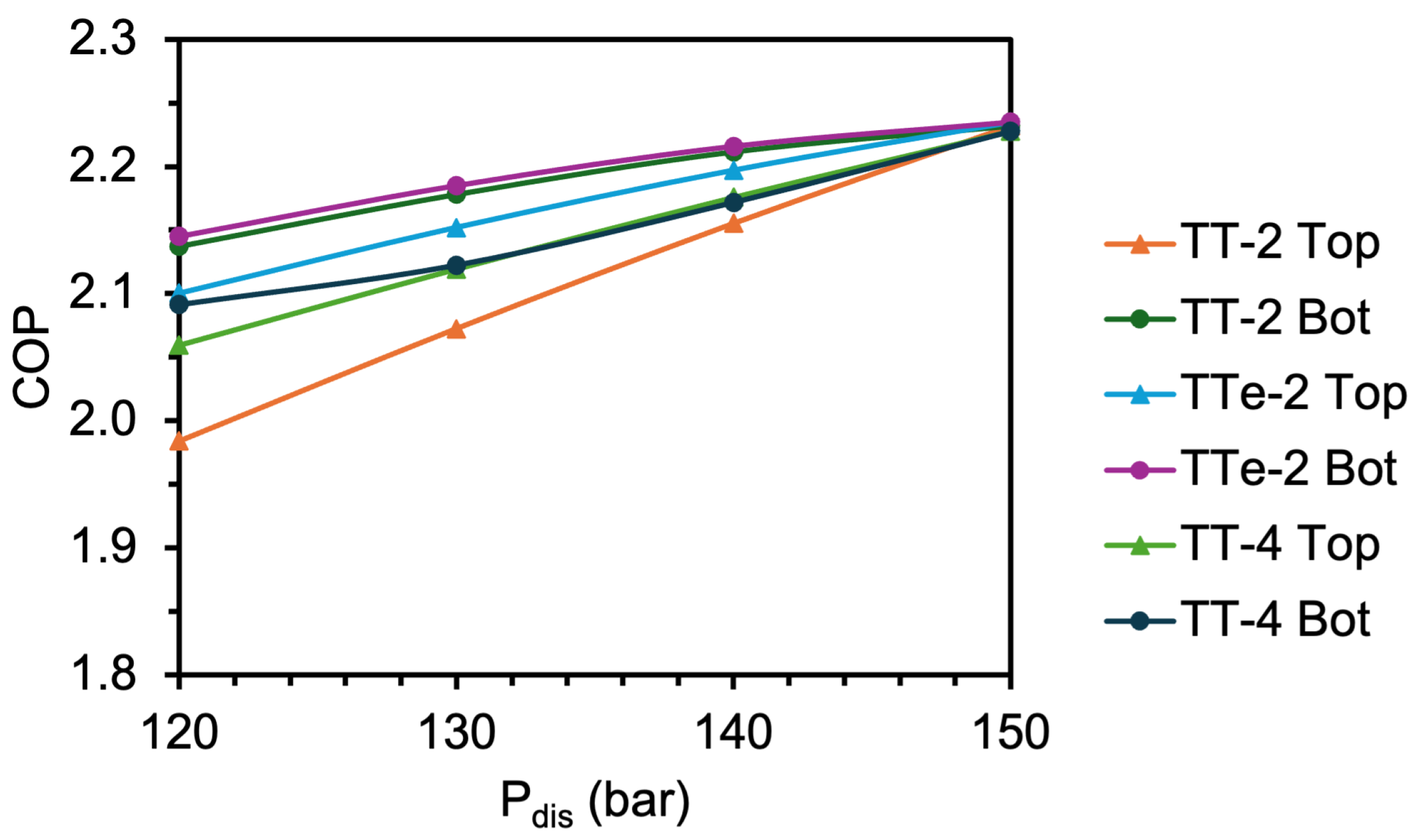
COPs of TT-2, TTe-2 and TT-4 at varying maximum pressures for one cycle/150 bar for the other cycle.
Figure 15.
COPs of TT-3, TTe-3 and TT-4 at varying maximum pressures for one cycle/150 bar for the other cycle.
Cycles TT-1 and TTe-1 (Figure 13) had nearly identical COPs for all discharge pressures investigated. Varying the pressure of the bottom cycle had a smaller effect on the COP than varying the pressure of the top cycle. For all pressures, TT-1 and TTe-1 had lower COPs than TT-4, except for an overlap between the TT-1 and TTe-1 bottom-cycle cases and the TT-4 top-cycle case at 120 bar. Similarly, the top-cycle discharge pressure had the largest effect on COP for TT-2 and TTe-2 (Figure 14), compared with the bottom-cycle discharge pressure. However, the negative effect on COP with decreasing discharge pressure was more prominent for TT-2 than TTe-2. Additionally, TTe-2 was able to achieve slightly higher COPs than TT-4 at the varying pressures, with the COPs of the three cycles converging at 150 bar. TT-3 and TTe-3 (Figure 15) were the most sensitive to changes in discharge pressure but consistently had lower performance than TT-4.
The same maximum discharge pressure for both the top and bottom cycles was also investigated. TT-1 and TTe-1 (Figure 16) had similar COPs, but both were lower than that of TT-4. Interestingly, TT-2 had higher COPs at lower pressures compared with TT-4, but the cycles converged to the same COP at 150 bar (Figure 17). The maximum pressure range was extended up to 200 bar, which showed that the COP of TT-4 was higher than TT-2 at pressures between 150 and 200 bar. Depending on compressor limitations, this supports the selection of cycle TT-2 when lower discharge pressures are required. However, as compressor technology improves and higher discharge pressures become more practical, TT-4 is likely to be the better-performing cycle. TT-3 had better performance than TTe-3 but not TT-4 for the discharge pressures investigated (Figure 18).
Figure 16.
COPs of TT-1, TTe-1 and TT-4 at varying maximum pressures for both cycles.
Figure 17.
COPs of TT-2, TTe-2 and TT-4 at varying maximum pressures for both cycles.
Figure 18.
COPs of TT-3, TTe-3 and TT-4 at varying maximum pressures for both cycles.
4. Conclusions
This study evaluated the integration of ejectors and expanders to reduce expansion exergy destruction in high-temperature transcritical–transcritical CO2 heat pump cycles for spray dryer air heating. Five ejector cycles and five expander cycles were analysed for the investigated spray dryer duty and compared with their corresponding baseline cycle concepts, with TT-4 retained as an external performance benchmark. No TT-4 recovery variant was developed. The placement of the ejectors and expanders within the cycles was informed by the component-level exergy destruction of the corresponding baseline configurations.
The key findings from this study are:
- Many of the ejector cycles required higher pressure ratios and higher gas cooler outlet temperatures to achieve the target sink temperature. Under the investigated conditions and assumed component efficiencies, ejectors reduced expansion losses in some cases, but these benefits were offset by penalties elsewhere in the cycle, particularly through degraded cascade heat exchanger performance and increased compressor work.
- The expander cycles achieved the highest COPs. TTX-2 achieved a COP of 2.35, 5.4% above its corresponding TT-2 baseline. TT-2 and the external benchmark TT-4 each achieved a COP of 2.23 at 150 bar for the investigated duty. The comparison with TT-4 was a benchmark comparison, not an evaluation of a TT-4 recovery variant.
- Although the COPs of the expander cycles were higher than their corresponding baseline cycles, the magnitude of this improvement was modest. As capital cost estimations for an appropriate CO2 expander were not readily available in the open literature, an upper-bound break-even capital cost of about 150 EUR/kW of delivered heat was calculated for the most favourable expander case. Under the same undiscounted 15-year assumptions, each additional 1 EUR/(kWth·year) of expander maintenance reduced this break-even value by 15 EUR/kWth.
- Cycles TT-2 and TT-4 exhibited similar COPs once the evaporation temperatures had been optimised at a discharge pressure of 150 bar. At discharge pressures below 150 bar, TT-2 achieved slightly higher COPs than TT-4 despite having one less heat exchanger. However, at discharge pressures above 150 bar, TT-4 had better performance.
The main limitations of this study are related to the modelling assumptions, including fixed isentropic efficiencies, steady-state operation, simplified ejector and expander representations, the assumed 0.03 MPa ejector pressure loss, and the neglect of detailed mechanical constraints. The reported relative performance is conditional on the fixed component efficiencies adopted in this study; higher recovery-device efficiencies would favour the ejector and expander configurations, whereas lower efficiencies would reduce their benefit. Similarly, a lower ejector pressure loss would favour the ejector cycles. These assumptions are particularly important for CO2 expanders operating near the critical point, where fluid properties vary strongly with small changes in temperature and pressure. The results represent one steady-state spray-drying duty and should not be generalised to other source temperatures, sink profiles, pressure limits, or operating regimes without further analysis. Future work should examine broader source and sink conditions and incorporate detailed component modelling, CFD analysis, and experimental validation to improve confidence in the predicted performance of ejector and expander cycles under high-temperature transcritical CO2 operating conditions.
Author Contributions
Conceptualization, L.K. and T.G.W.; Methodology, L.K.; Software, L.K.; Validation, L.K.; Investigation, L.K. and F.S.; Writing—original draft, L.K.; Writing—review & editing, F.S., S.K., J.K.C., D.J.C. and T.G.W.; Visualization, L.K.; Supervision, F.S., S.K., J.K.C., D.J.C. and T.G.W.; Project administration, T.G.W.; Funding acquisition, J.K.C., D.J.C. and T.G.W. All authors have read and agreed to the published version of the manuscript.
Funding
This research was funded by the Ministry of Business, Innovation and Employment, New Zealand, through the program “Ahuora: Delivering sustainable industry through smart process heat decarbonisation”, an Advanced Energy Technology Platform.
Data Availability Statement
The original contributions presented in this study are included in the article. Further inquiries can be directed to the corresponding author.
Conflicts of Interest
The authors declare no conflicts of interest.
Nomenclature
| Abbreviation | Definition |
| CGC | Cascade gas cooler |
| CO2 | Carbon dioxide |
| COP | Coefficient of performance |
| DOI | Digital object identifier |
| GC | Gas cooler |
| GWP | Global warming potential |
| HTHP | High-temperature heat pump |
| HTTHP | High-temperature transcritical heat pump |
| IHX | Internal heat exchanger |
| ODP | Ozone depletion potential |
| PLR | Pressure lift ratio for an ejector |
| sCO2 | Supercritical carbon dioxide |
| T1 | Single-stage transcritical CO2 cycle |
| T1e | Single-stage transcritical CO2 cycle with ejector |
| TX | Single-stage transcritical CO2 cycle with expander |
| TT | Transcritical–transcritical cascade CO2 cycle |
| TTe | Transcritical–transcritical cascade CO2 cycle with ejector |
| TTX | Transcritical–transcritical cascade CO2 cycle with expander |
| Symbols | Definition |
| Minimum approach temperature (°C or K) | |
| Entrainment ratio | |
| Efficiency (%) | |
| Absolute humidity (kgH2O/kg of dry air) | |
| Specific heat capacity (kJ/kgK) | |
| h | Specific enthalpy (kJ/kg) |
| Mass flow rate (kg/s) | |
| P | Pressure (MPa or bar) |
| s | Specific entropy (kJ/kg·K) |
| T | Temperature (°C) |
| w | Specific work consumption (kJ/kg) |
| Work (kW) | |
| x | Specific exergy (kJ/kg) or vapour quality |
| Exergy flow (kW) | |
| Subscript | Definition |
| 0 | Dead state or reference environment |
| act | Actual |
| air | Air stream |
| ann | Annual |
| be | Break-even |
| bot | Bottom cycle |
| comp | Compressor |
| diff | Diffuser |
| dis | Compressor discharge |
| des | Destruction |
| eject | Ejector |
| elec | Electricity |
| evap | Evaporator |
| exp | Expander |
| gc | Gas cooler |
| h | Hot stream |
| hp | Heat pump |
| I | Ejector primary flow |
| II | Ejector secondary flow |
| ihx | Internal heat exchanger |
| in | Inlet |
| is | Isentropic |
| life | Lifetime |
| max | Maximum |
| mech | Mechanical |
| mix | Ejector mixed flow |
| n | Nozzle |
| out | Outlet |
| ref | Refrigerant |
| sink | Heat sink stream |
| source | Heat source stream |
| top | Top cycle |
| tot | Total |
References
- Klinac, E.; Carson, J.K.; Hoang, D.; Chen, Q.; Cleland, D.J.; Walmsley, T.G. Multi-Level Process Integration of Heat Pumps in Meat Processing. Energies 2023, 16, 3424. [Google Scholar] [CrossRef] [Scilit]
- Madeddu, S.; Ueckerdt, F.; Pehl, M.; Peterseim, J.; Lord, M.; Kumar, K.A.; Krüger, C.; Luderer, G. The CO2 Reduction Potential for the European Industry via Direct Electrification of Heat Supply (Power-to-Heat). Environ. Res. Lett. 2020, 15, 124004. [Google Scholar] [CrossRef] [Scilit]
- Bühler, F.; Zühlsdorf, B.; Nguyen, T.-V.; Elmegaard, B. A Comparative Assessment of Electrification Strategies for Industrial Sites: Case of Milk Powder Production. Appl. Energy 2019, 250, 1383–1401. [Google Scholar] [CrossRef] [Scilit]
- Brendel, L.P.M.; Bernal, S.N.; Arpagaus, C.; Roskosch, D.; Bardow, A.; Bertsch, S.S. Experimental Performance Comparison of High-Glide Hydrocarbon and Synthetic Refrigerant Mixtures in a High-Temperature Heat Pump. Energies 2024, 17, 1981. [Google Scholar] [CrossRef] [Scilit]
- Hamid, K.; Ren, S.; Tolstorebrov, I.; Hafner, A.; Sajjad, U.; Arpagaus, C.; Moen, O.M.; Eikevik, T.M. Experimental Optimization of an Absorption-Compression Heat Pump with Wet Compression for Large Temperature Glide Industrial Applications. Renew. Energy 2025, 243, 122531. [Google Scholar] [CrossRef] [Scilit]
- Arpagaus, C.; Bless, F.; Uhlmann, M.; Schiffmann, J.; Bertsch, S.S. High Temperature Heat Pumps: Market Overview, State of the Art, Research Status, Refrigerants, and Application Potentials. Energy 2018, 152, 985–1010. [Google Scholar] [CrossRef] [Scilit]
- Adamson, K.-M.; Walmsley, T.G.; Carson, J.K.; Chen, Q.; Schlosser, F.; Kong, L.; Cleland, D.J. High-Temperature and Transcritical Heat Pump Cycles and Advancements: A Review. Renew. Sustain. Energy Rev. 2022, 167, 112798. [Google Scholar] [CrossRef] [Scilit]
- Arpagaus, C. High-Temperature Heat Pumps: Market Overview, State of the Art, and Application Potential. Clean Technol. Environ. Policy 2026, 28, 148. [Google Scholar] [CrossRef] [Scilit]
- Brendel, L.P.M.; Bernal, S.N.; Widmaier, P.; Roskosch, D.; Arpagaus, C.; Bardow, A.; Bertsch, S.S. High-Glide Refrigerant Blends in High-Temperature Heat Pumps: Part 1—Coefficient of Performance. Int. J. Refrig. 2024, 165, 84–96. [Google Scholar] [CrossRef] [Scilit]
- Sarkar, J.; Bhattacharyya, S.; Ram Gopal, M. Natural Refrigerant-Based Subcritical and Transcritical Cycles for High Temperature Heating. Int. J. Refrig. 2007, 30, 3–10. [Google Scholar] [CrossRef] [Scilit]
- ANSI/ASHRAE Standard 34-2022; Designation and Safety Classification of Refrigerants. American Society of Heating, Refrigerating and Air-Conditioning Engineers (ASHRAE): Peachtree Corners, GA, USA, 2022.
- Walmsley, T.G.; Adamson, K.-M.; Arpagaus, C.; Schlosser, F. Recuperative Heat Pump Cycle Concept for High-Temperature Glide Process Heating Applications. Appl. Therm. Eng. 2026, 301, 131660. [Google Scholar] [CrossRef] [Scilit]
- Hoang, D.K.; Walmsley, T.G.; Cleland, D.J.; Chen, Q.; Carson, J.K. Thermo-Economic Investigation and Multi Objective Optimization of Cascade High Temperature Heat Pump Using Low Global Warming Refrigerants. Appl. Therm. Eng. 2025, 279, 127901. [Google Scholar] [CrossRef] [Scilit]
- Ma, Y.; Liu, Z.; Tian, H. A Review of Transcritical Carbon Dioxide Heat Pump and Refrigeration Cycles. Energy 2013, 55, 156–172. [Google Scholar] [CrossRef] [Scilit]
- Kong, L.; Kloeppel, S.; Schlosser, F.; Kabat, N.; Carson, J.K.; Walmsley, T.G. Advances in High-Temperature Heat Pump Technologies for Industrial Process Applications with Large Temperature Glides: Assessing the Potential for Carbon Dioxide as a Refrigerant. Energy Convers. Manag. 2026, 350, 120933. [Google Scholar] [CrossRef] [Scilit]
- Sarkar, J.; Bhattacharyya, S.; Gopal, M.R. Optimization of a Transcritical CO2 Heat Pump Cycle for Simultaneous Cooling and Heating Applications. Int. J. Refrig. 2004, 27, 830–838. [Google Scholar] [CrossRef] [Scilit]
- Kong, L.; Walmsley, T.G.; Hoang, D.K.; Schlosser, F.; Chen, Q.; Carson, J.K.; Cleland, D.J. Transcritical-Transcritical Cascade CO2 Heat Pump Cycles for High-Temperature Heating: A Numerical Evaluation. Appl. Therm. Eng. 2024, 238. [Google Scholar] [CrossRef] [Scilit]
- Qin, X.; Lei, S.; Liu, H.; Zeng, Y.; Liu, Y.; Pang, C.; Chen, J. Comparative Analysis of Transcritical CO2 Heat Pump Systems with and Without Ejector: Performance, Exergy, and Economic Perspective. Energies 2025, 18, 3223. [Google Scholar] [CrossRef] [Scilit]
- Manno, M.; Gambini, M.; Vellini, M. Energy and Exergy Analysis of Transcritical CO2 Cycles for Heat Pump Applications. Sustainability 2024, 16, 7511. [Google Scholar] [CrossRef] [Scilit]
- Zhang, Z.; Feng, X.; Tian, D.; Yang, J.; Chang, L. Progress in Ejector-Expansion Vapor Compression Refrigeration and Heat Pump Systems. Energy Convers. Manag. 2020, 207, 112529. [Google Scholar] [CrossRef] [Scilit]
- Sumeru, K.; Nasution, H.; Ani, F.N. A Review on Two-Phase Ejector as an Expansion Device in Vapor Compression Refrigeration Cycle. Renew. Sustain. Energy Rev. 2012, 16, 4927–4937. [Google Scholar] [CrossRef] [Scilit]
- Song, Y.; Ma, Y.; Wang, H.; Yin, X.; Cao, F. Review on the Simulation Models of the Two-Phase-Ejector Used in the Transcritical Carbon Dioxide Systems. Int. J. Refrig. 2020, 119, 434–447. [Google Scholar] [CrossRef] [Scilit]
- Ringstad, K.E.; Allouche, Y.; Gullo, P.; Ervik, Å.; Banasiak, K.; Hafner, A. A Detailed Review on CO2 Two-Phase Ejector Flow Modeling. Therm. Sci. Eng. Prog. 2020, 20, 100647. [Google Scholar] [CrossRef] [Scilit]
- Elbel, S.; Hrnjak, P. Experimental Validation of a Prototype Ejector Designed to Reduce Throttling Losses Encountered in Transcritical R744 System Operation. Int. J. Refrig. 2008, 31, 411–422. [Google Scholar] [CrossRef] [Scilit]
- You, C.; Michel, B.; Revellin, R. Transcritical Carbon Dioxide Heat Pump Cycle: Validation and Comparison of One-Dimensional Models of Ejector with Independent Data Sets. Appl. Therm. Eng. 2022, 213, 118668. [Google Scholar] [CrossRef] [Scilit]
- Linnhoff, B.; Flower, J.R. Synthesis of Heat Exchanger Networks: I. Systematic Generation of Energy Optimal Networks. AIChE J. 1978, 24, 633–642. [Google Scholar] [CrossRef] [Scilit]
- Schlosser, F.; Arpagaus, C.; Walmsley, T.G. Heat Pump Integration by Pinch Analysis for Industrial Applications: A Review. Chem. Eng. Trans. 2019, 76, 7–12. [Google Scholar] [CrossRef] [Scilit]
- Schlosser, F.; Wiebe, H.; Walmsley, T.G.; Atkins, M.J.; Walmsley, M.R.W.; Hesselbach, J. Heat Pump Bridge Analysis Using the Modified Energy Transfer Diagram. Energies 2021, 14, 137. [Google Scholar] [CrossRef] [Scilit]
- Yang, M.; Li, T.; Feng, X.; Wang, Y. A Simulation-Based Targeting Method for Heat Pump Placements in Heat Exchanger Networks. Energy 2020, 203, 117907. [Google Scholar] [CrossRef] [Scilit]
- Walmsley, T.G.; Lincoln, B.J.; Padullés, R.; Cleland, D.J. Advancing Industrial Process Electrification and Heat Pump Integration with New Exergy Pinch Analysis Targeting Techniques. Energies 2024, 17, 2838. [Google Scholar] [CrossRef] [Scilit]
- Walmsley, T.G. OpenPinch (Github). Available online: https://github.com/waikato-ahuora-smart-energy-systems/OpenPinch (accessed on 3 October 2025).
- Walmsley, T.G. OpenPinch: An Open-Source Python Library for Advanced Pinch Analysis and Total Site Integration. Process Integr. Optim. Sustain. 2026. [Google Scholar] [CrossRef] [Scilit]
- Stampfli, J.A.; Atkins, M.J.; Olsen, D.G.; Walmsley, M.R.W.; Wellig, B. Practical Heat Pump and Storage Integration into Non-Continuous Processes: A Hybrid Approach Utilizing Insight Based and Nonlinear Programming Techniques. Energy 2019, 182, 236–253. [Google Scholar] [CrossRef] [Scilit]
- Wallerand, A.S.; Kermani, M.; Kantor, I.; Maréchal, F. Optimal Heat Pump Integration in Industrial Processes. Appl. Energy 2018, 219, 68–92. [Google Scholar] [CrossRef] [Scilit]
- Atkins, M.J.; Walmsley, M.R.W.; Neale, J.R. Integrating Heat Recovery from Milk Powder Spray Dryer Exhausts in the Dairy Industry. Appl. Therm. Eng. 2011, 31, 2101–2106. [Google Scholar] [CrossRef] [Scilit]
- Lincoln, B.J.; Kong, L.; Pineda, A.M.; Walmsley, T.G. Process Integration and Electrification for Efficient Milk Evaporation Systems. Energy 2022, 258, 124885. [Google Scholar] [CrossRef] [Scilit]
- Schlosser, F.; Zysk, S.; Walmsley, T.G.; Kong, L.; Zühlsdorf, B.; Meschede, H. Break-Even of High-Temperature Heat Pump Integration for Milk Spray Drying. Energy Convers. Manag. 2023, 291, 117304. [Google Scholar] [CrossRef] [Scilit]
- Kong, L. New High Temperature Transcritical CO2 Heat Pump Concept for Spray Drying. Ph.D. Thesis, University of Waikato, Hamilton, New Zealand, 2026. [Google Scholar]
- NIST Reference Fluid Thermodynamic and Transport Properties Database. Available online: https://www.nist.gov/srd/refprop (accessed on 3 November 2018).
- Lemmon, E.W.; Bell, I.H.; Huber, M.L.; McLinden, M.O. NIST Standard Reference Database 23: Reference Fluid Thermodynamic and Transport Properties–REFPROP, Version 10.0; National Institute of Standards and Technology: Gaithersburg, MD, USA, 2018. [Google Scholar] [CrossRef]
- Zhu, Y.; Li, C.; Zhang, F.; Jiang, P.-X. Comprehensive Experimental Study on a Transcritical CO2 Ejector-Expansion Refrigeration System. Energy Convers. Manag. 2017, 151, 98–106. [Google Scholar] [CrossRef] [Scilit]
- Li, D.; Groll, E.A. Transcritical CO2 Refrigeration Cycle with Ejector-Expansion Device. Int. J. Refrig. 2005, 28, 766–773. [Google Scholar] [CrossRef] [Scilit]
- Du, Y.; Tian, G.; Pekris, M. A Comprehensive Review of Micro-Scale Expanders for Carbon Dioxide Related Power and Refrigeration Cycles. Appl. Therm. Eng. 2022, 201, 117722. [Google Scholar] [CrossRef] [Scilit]
- Wolscht, L.; Knobloch, K.; Jacquemoud, E.; Jenny, P. Dynamic Simulation and Experimental Validation of a 35 MW Heat Pump Based on a Transcritical CO2 Cycle. Energy 2024, 294, 130897. [Google Scholar] [CrossRef] [Scilit]
- Zühlsdorf, B.; Meesenburg, W.; Ommen, T.S.; Thorsen, J.E.; Markussen, W.B.; Elmegaard, B. Improving the Performance of Booster Heat Pumps Using Zeotropic Mixtures. Energy 2018, 154, 390–402. [Google Scholar] [CrossRef] [Scilit]
- Palacz, M.; Bodys, J.; Haida, M.; Smolka, J.; Nowak, A.J. Two-Phase Flow Visualisation in the R744 Vapour Ejector for Refrigeration Systems. Appl. Therm. Eng. 2022, 210, 118322. [Google Scholar] [CrossRef] [Scilit]
- Span, R.; Wagner, W. A New Equation of State for Carbon Dioxide Covering the Fluid Region from the Triple-Point Temperature to 1100 K at Pressures up to 800 MPa. J. Phys. Chem. Ref. Data 1996, 25, 1509–1596. [Google Scholar] [CrossRef] [Scilit]

Disclaimer/Publisher’s Note: The statements, opinions and data contained in all publications are solely those of the individual author(s) and contributor(s) and not of MDPI and/or the editor(s). MDPI and/or the editor(s) disclaim responsibility for any injury to people or property resulting from any ideas, methods, instructions or products referred to in the content. |
© 2026 by the authors. Licensee MDPI, Basel, Switzerland. This article is an open access article distributed under the terms and conditions of the Creative Commons Attribution (CC BY) license.