


Abstract
In this work, Direct Numerical Simulation (DNS) investigates the combustion behaviour of a reactive transverse lean premixed jet of an ammonia blend (10% NH3, 11% H2, 16% O2 and 63% N2 by volume) injected through a rectangular nozzle in a pre-heated non-vitiated air crossflow at a pressure of 5 bar. The configuration has been chosen from a Reynolds-Averaged Navier–Stokes (RANS) test campaign to ensure low NO and low unburned fuel, while maintaining a high temperature profile at the turbine inlet. The DNS shows that the flame stabilises on the leeward side of the rectangular jet, within and downstream of the recirculation region, while high scalar dissipation and short residence times prevent persistent anchoring on the windward side. Joint statistics reveal that the reaction does not follow a constant equivalence ratio path, since intermediate progress states are shifted towards leaner mixtures by entrainment, dilution and differential diffusion. The strongest heat-release and displacement-speed events occur in localised regions where mixture state, stretch and flame-front geometry act jointly. The displacement-speed budget is mainly controlled by the chemical source term, with diffusion reducing the net propagation speed and stratification-induced cross terms remaining small. Under intense stretch, positively curved flame elements exhibit larger displacement speeds, indicating a coupled effect of curvature, preferential diffusion and local radical transport. NO formation is dominated by fuel-nitrogen chemistry: HNO and NH2 are the main NO-producing routes, whereas N2 and N2O provide the dominant NO-sink channels. The DNS predicts an outlet-averaged NO level of 400 dppm, while extended-domain RANS calculations indicate that longer residence times could reduce it below 100 dppm.
1. Introduction
The pursuit of decarbonising energy systems has spurred intensive research into alternative fuels and combustion technologies. Among the promising candidates, ammonia (NH3) stands out due to its carbon-free composition, high energy density, and established infrastructure for production, storage, and transportation [1]. However, its relatively low reactivity and high nitrogen oxide (NOx) formation propensity pose significant challenges for practical applications [2,3], particularly in demanding environments like micro-gas turbines (mGTs). To address these issues, hydrogen (H2) addition has emerged as a viable strategy to enhance flame speed and stability [3,4], while nitrogen (N2) dilution can be employed to control NOx emissions [5,6]. Furthermore, research on partially decomposed ammonia-air flames has contributed to the development of thermal decomposition technologies [7], and catalytic methods using cracked ammonia have achieved successful power generation [8,9]. Investigations into ammonia-methane blends have also highlighted the importance of optimised injection methods for ammonia-based fuels [10]. In this context, the combustion chamber of mGTs often features micro-mixing combustion strategies, such as a Jet in Crossflow (JICF) configuration, where a fuel jet is injected into a hot crossflow of air. This technological solution is commonly adopted in axial-fuel-staged (AFS) combustion, where the JICF plays a pivotal role in the secondary combustion stage, and is particularly effective in reducing NOx emissions by minimising high-temperature residence times, which is of particular importance in advanced J-class turbines [11,12,13,14,15,16].
In ammonia combustion modelling, research has focused on the combustion processes of both pure NH3 and NH3/H2 fuel blends to identify appropriate mechanisms for assessing NOx emissions, aiming to improve understanding of pollutant formation and reduction strategies [17,18]. From the numerical point of view, the complex interaction between turbulence and combustion has been a subject of great interest for researchers. In particular, studies have focused on the structures and interactions of turbulent premixed and non-premixed flames, examining their dynamics, stabilisation mechanisms, and the influence of key parameters such as equivalence ratio and chemical kinetics. For instance, Rieth et al. [19] presented a detailed analysis of NO and N2O formation using temporally evolving turbulent planar jet and shear layer configurations, specifically evaluating the influence of equivalence ratio and pressure (up to 10 bar) on global formation rates. Similarly, Karimkashi et al. [20] explored NO formation pathways in planar premixed flames subjected to decaying turbulence at atmospheric pressure, highlighting how hydrogen enrichment and local curvature modify the HNO and N2O routes. While these studies have successfully employed DNS to investigate the fundamental chemical pathways of NH3/H2 combustion, they have primarily focused on basic or idealised flow configurations. Recently, Tian et al. [21] performed DNS on ammonia/air premixed slot jet flames, investigating the impact of turbulence intensity and partial ammonia cracking on turbulence–flame interactions and NO emission characteristics. Their findings highlighted the complexities of ammonia combustion under varying conditions. Cecere et al. [22] numerically investigated a premixed NH3/H2/N2-air slot flame at high equivalence ratio and 25 bar pressure, presenting insights into NOx production and emphasising the effect of the H2 preferential diffusion on the flame local equivalence ratio, which decreases for negative curvatures, resulting in a NO peak that exceeds the corresponding value in laminar flames. Giacomazzi et al. [23] employed DNS to analyse a non-premixed flame burning a fuel mixture derived from ammonia partial decomposition, injected into an air crossflow under conditions typical of micro-gas turbines. They found that both non-premixed and premixed modes arise in the flame, with the non-premixed mode dominating in volume and occuring in high-strain regions, leading to higher NO production. They highlight the potential to generate a premixed region in a nominally non-premixed setup, even if controlling mixing and stoichiometry of the premixed combustion mode could be a critical challenge. Cecere et al. [24] investigated the combined effects of fuel composition and injection angle of a non-premixed NH3/H2/N2 jet in an air crossflow, under conditions common in mGTs, using high-fidelity Large Eddy Simulations (LES). They examined four distinct fuel mixtures, derived from ammonia partial decomposition with hydrogen concentrations ranging from 15% to 60% by volume, which have been injected at angles of 90° and 75°. Their findings reveal that lower hydrogen content flames yield higher temperatures and increased NO production due to enhanced ammonia-to-hydrogen conversion. As hydrogen concentration increases, this conversion decreases, leading to lower NO emissions and unburned fuel, particularly at the low injection angle.
From the available literature, it emerges that understanding the complex interplay between the fuel components and the turbulent flow field is crucial for optimising the design and operation of NH3/H2/N2-fueled mGTs. Specifically, the high Reynolds number, complex chemistry, and strong turbulence-chemistry interaction characteristic of mGT environments present significant computational challenges. For this reason, the accurate representation of ammonia/hydrogen combustion chemistry, including the formation and consumption of intermediate species, is essential for predicting flame propagation and pollutant emissions and necessitates a high-fidelity numerical approach. Furthermore, while fundamental DNS studies have addressed lean premixed ammonia combustion in planar configurations [19] and stoichiometric mixtures in decaying turbulence [20], there is a notable lack of high-fidelity investigations concerning lean premixed blends in complex, technologically relevant architectures. Specifically, existing research on ammonia-fueled JICF has primarily focused on non-premixed injection strategies [23,24], leaving the stabilisation mechanisms and pollutant formation of lean premixed JICF under typical micro-gas turbine conditions largely unexplored. For these reasons, in this manuscript, we aim to study a lean premixed NH3/H2/N2/air jet in crossflow at mGT-relevant conditions by means of DNS. The main goal is to provide detailed insights into the flame structure, mixing, flame stabilisation, and pollutant formation mechanisms. By resolving the intricate interactions between the fuel jet, crossflow, and combustion processes, we seek to advance the understanding of ammonia/hydrogen blend combustion and contribute to the development of cleaner and more efficient energy conversion technologies. The results obtained will be analysed to investigate the effect of the premixing on the flame dynamics and pollutant emissions, providing valuable data for the design and optimisation of future mGT combustion systems.
2. Test Case Computational Setup
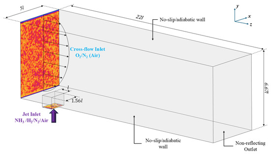
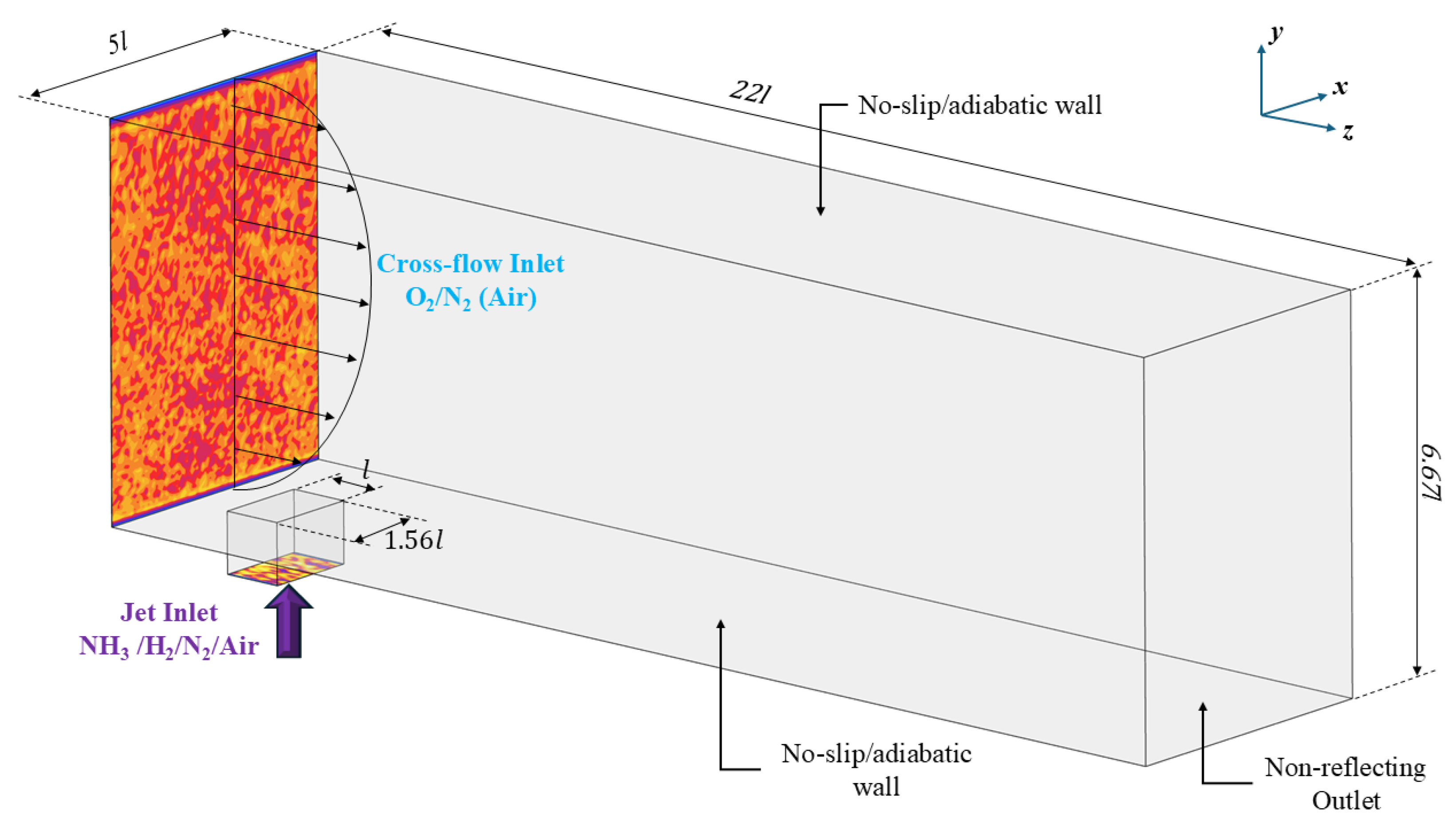
To investigate the combustion behaviour of a reactive transverse premixed jet of NH3/H2/O2/N2 within a pre-heated, non-vitiated air crossflow at 5 bar pressure, the three-dimensional compressible Navier–Stokes (N-S) equations are solved [25]. To this end, the reactant mixture is injected into the crossflow through a rectangular nozzle of dimensions , with . The combustion chamber measures in the streamwise, wall-normal, and spanwise directions, respectively. The crossflow air temperature is 850 K, representing a typical value at the end of the compression stage in stationary gas turbines, while the fuel jet temperature is 750 K, consistent with the thermal cracking of ammonia. The boundary conditions for the simulation are prescribed as follows: the air crossflow and the fuel jet enter the domain through an inflow boundary, where velocity, temperature, velocity fluctuations (≈5% of the velocity), and composition are fixed. An adiabatic and no-slip condition is applied at the lower and upper walls of the chamber, as well as to all the walls of the rectangular channel of the jet inlet. Periodic boundary conditions are applied in the spanwise direction. The combustion products exit the domain through a non-reflecting outlet boundary. This choice is important to avoid pressure disturbances being reflected back toward the flame region. A schematic representation of the domain and boundary conditions is depicted in Figure 1.
Figure 1.
Schematic of the computational domain and boundary conditions for the DNS simulation.
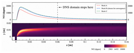
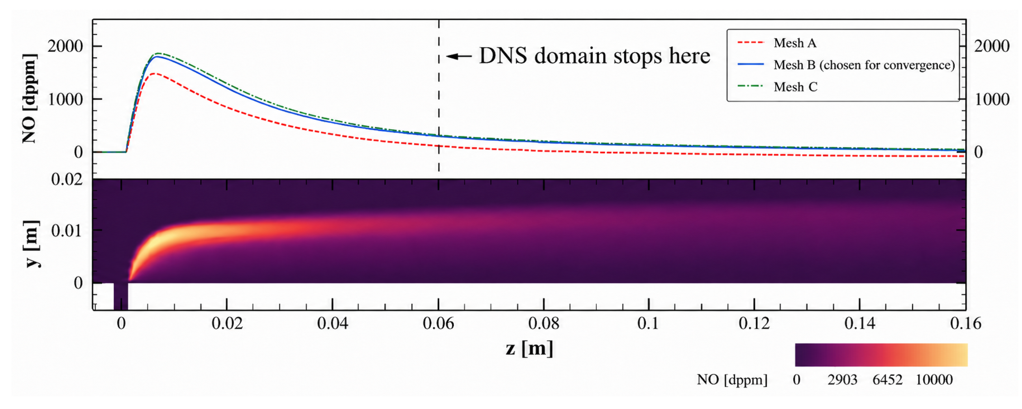
In order to choose the most promising configuration to investigate, a numerical campaign of steady-state three-dimensional RANS simulations has been performed with ANSYS Fluent 2023R2. A set of different nominal () and global () equivalence ratios has been investigated. The former is the equivalence ratio of the injected premixed fuel mixture, while the latter is the equivalence ratio obtained by mixing the fuel jet and the air crossflow by only changing the crossflow velocity. The resulting test matrix of all the configurations studied is reported in Table 1. The Reynolds Stress Model (RSM) was adopted in conjunction with the Eddy Dissipation Concept (EDC) combustion model, employing the same detailed chemical mechanism used in the DNS simulation (see below). Transport properties were evaluated based on kinetic gas theory, and volumetric chemical reactions were treated using a stiff chemistry solver. Thermal diffusion effects (Soret effect) were also taken into account in the species transport formulation. Turbulence effects in the energy and species conservation equations were accounted for through the eddy-diffusivity approximation. The turbulent heat flux was modelled using a turbulent Prandtl number of Prt = 0.85, while turbulent species diffusion was modelled using a turbulent Schmidt number of Sct = 0.70. These values were kept constant throughout the simulations. A pressure-based solver, the SIMPLE scheme for pressure-velocity coupling, a second-order upwind scheme for spatial discretisation, and a third-order MUSCL scheme for species and energy were adopted. The RANS computations were performed on a structured/unstructured hybrid polyhedral mesh composed of approximately 11M cells. The mesh was refined in the injector region, along the JICF shear layers, near walls, inside recirculation zones, and throughout the main reaction region. In particular, near walls, the mesh was designed using an inflation layer to satisfy the target wall-resolution requirement associated with the adopted turbulence model, with y+ ∼ 1. Mesh adequacy was verified through a grid-sensitivity analysis on three mesh levels (Mesh A = 5M cells, Mesh B = 11M cells, and Mesh C = 20M cells). The results of the grid sensitivity are shown in Figure 2, which shows negligible variations in the observable on further refinement. The intermediate grid (B) was therefore adopted for the RANS parametric campaign. It is worth noting that, for the RANS computations, the computational domain in the streamwise direction is much longer than that of DNS (), to investigate the effect of a greater residence time inside the chamber.
Table 1.
RANS simulations test matrix. Green and bold line highlights the case chosen for DNS.
Figure 2.
NO concentration field [dppm] from the converged RANS simulation in the mid-plane of the domain, and spatial footprint of the cross-sectionally averaged NO [dppm] for three levels of mesh. For the sake of visualisation, only a part of the domain is shown.
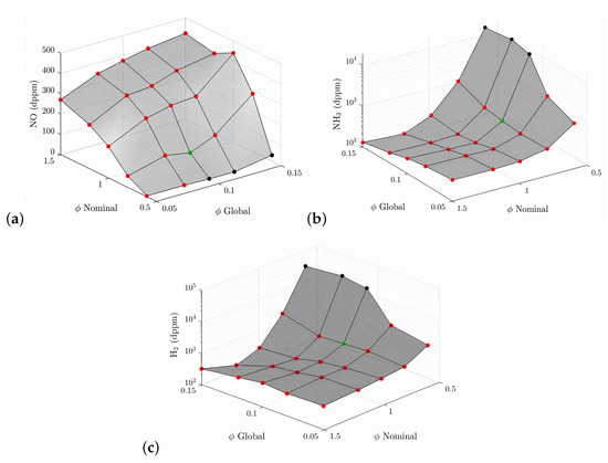
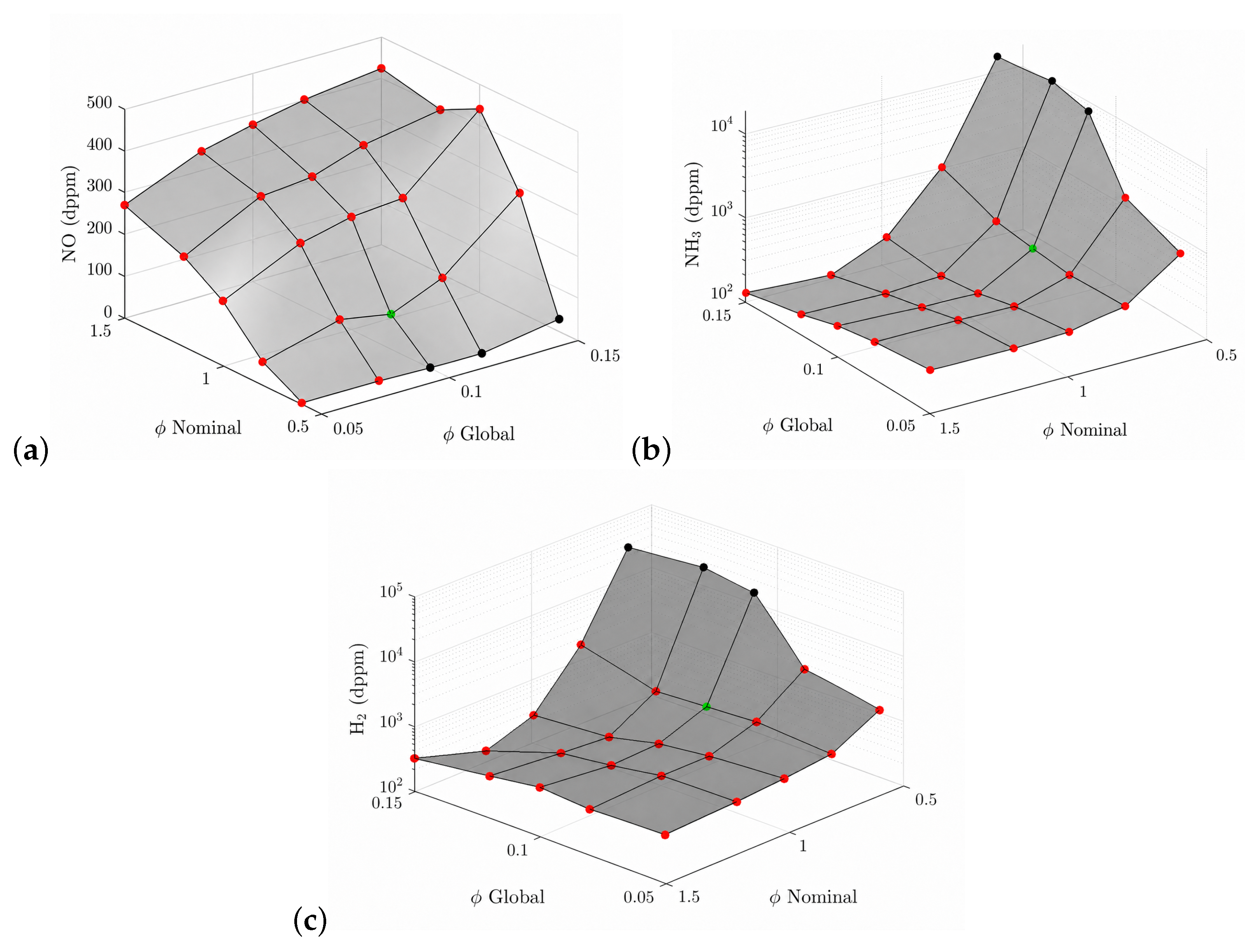
The results of the RANS campaign are reported in Figure 3, which shows the average NO, NH3, and H2 concentrations in dppm at the exit of the combustion chamber. In the figure, the red dots represent the configurations with a stable and ignited flame, while the black dots represent the configurations where the flame has extinguished. The case that has been chosen is that with and (green dot), which is the most promising in terms of low NO, low unburned ammonia and hydrogen, and with the highest possible temperature for the inlet of a turbine [26]. Figure 2 shows the NO concentration contour field from the RANS calculations of the chosen configuration as an example. As the flow develops downstream, NO concentrations continue to decrease until reaching an asymptotic plateau, as shown in the top panel of the figure, where the axial evolution of the cross-sectionally averaged NO concentration drops to approximately 83 dppm in the extended portion of the domain.
Figure 3.
Results of the RANS simulations test matrix for different nominal and global equivalence ratios: average NO (a), average NH3 (b), and average H2 (c). The red dots represent the configurations with a stable burning flame. The black dots represent configurations where the flame is extinguished. The green dot represents the case chosen for DNS ( and ; dppm, dppm, and dppm). The value of the concentrations is in dppm and is averaged on the outlet section of the combustion chamber. The RANS computations have a streamwise dimension of the domain that is longer than that of the DNS ( vs. ).
The chosen configuration employed for the DNS has a mixture of 10% NH3, 11% H2, 16% O2 and 63% N2 by volume. The crossflow freestream velocity () is 8.59 m/s, and the jet velocity () is 30 m/s, resulting in a velocity ratio (r) of 3.49 and a momentum flux ratio (J) of 11.87. The jet Reynolds number is approximately 5165. A summary of the DNS nominal inlet flow conditions is reported in Table 2.
Table 2.
Main flow and thermochemical parameters of the DNS configuration ( and ). For the jet mixture, the unstretched laminar flame speed is and the flame-front thickness is .
Regarding the DNS computational grid, the first cell height near the lower wall is set to ≈5 µm, which is the same discretisation adopted in the vicinity of the jet core. Based on inlet conditions and local turbulent Reynolds number (), the estimated Kolmogorov scales are µm for the crossflow and µm for the jet. The used mesh consists of grid points, resulting in approximately 1.76 billion cells, which ensures that the flame front is resolved with at least eight grid points. After initialisation, the DNS was advanced, with a time step of s, for an initial transient interval of s before statistical sampling was started. Statistical quantities were then accumulated over an averaging interval of 0.015 s, corresponding to approximately two characteristic flow-through times based on the bulk crossflow velocity and DNS domain length.
The Hirschfelder and Curtiss [27] approximation is employed to model the molecular transport within the multicomponent mixture, which also incorporates the Soret thermo-diffusion effect and pressure gradient diffusion. Binary diffusion coefficients and thermo-diffusion coefficients for each species are calculated on-the-fly using kinetic theory expressions. Individual species’ dynamic viscosity and thermal conductivity are pre-computed using software libraries [28,29]. Mixture-averaged properties are determined with Wilke’s formula [30], with Bird’s correction [31] for viscosity, and Mathur’s expression [32] for thermal conductivity. The Hirschfelder and Curtiss law [27] is employed for the preferential diffusion modelling. Chemical reactions are modelled using the mechanism of Jiang [33], which involves 19 chemical species and 64 reactions. This scheme has been improved for formation considering combustion at high pressure [17]. Valera-Medina et al. [34] recently showed that this reduced kinetic mechanism lies well within the observed data of several well-known detailed models.
The DNS is carried out using the in-house parallel code HeaRT [35,36,37,38] on ENEA’s CRESCO supercomputing facility [39]. The code solves the compressible N-S equations, exploiting staggered finite-difference schemes, with individual transport equations for each chemical species. Diffusive fluxes are computed by means of a second-order accurate centred scheme, while convective terms are modelled using the - method [40], combined with a third/fifth-order accurate WENO interpolation to minimise spurious oscillations. Extended non-reflecting boundary conditions [41,42,43] are applied at open boundaries, accounting for the effects of variable transport properties [44] and local heat release [45]. A synthetic turbulence generator is used at the inlets [46].
3. Results
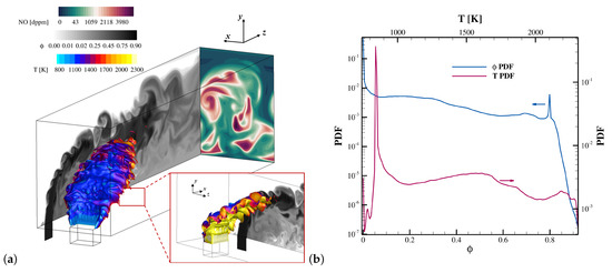
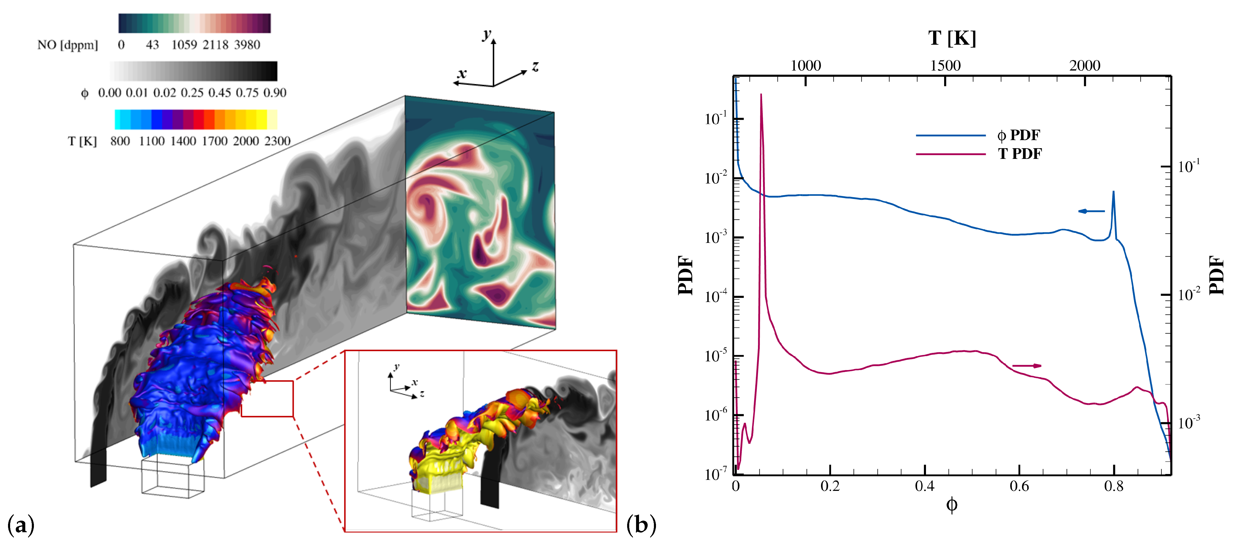
A brief overview of the flow topology of the present configuration is first provided in Figure 4a, which reports an iso-surface of heat release rate at , coloured by temperature, together with a slice of the equivalence ratio at (for clarity, this slice is projected onto the outer periodic plane) and a slice of NO concentration at the outlet plane. Heat release first develops along the shorter sides of the rectangular outlet section of the fuel jet and on its leeward side. Over this surface, the temperature ranges between 2000 and 2200 K, depending on the local mixture fraction, scalar dissipation rate and equivalence ratio. As these lateral flame regions are convected downstream, they progressively cool due to enhanced mixing with the crossflow air induced by the large vortical structures. Immediately downstream of the injector, a recirculation region approximately 1 cm long forms near the lower wall, where combustion products rapidly mix with air.
Figure 4.
(a) Instantaneous volume rendering of the heat release rate iso-surface at coloured by temperature, together with a slice of the equivalence ratio at (gray-scale colourmap) and a slice of NO concentration [dppm] at the outlet plane (ocean curl colourmap); (b) volume-weighted PDFs of and T.
Figure 4a also highlights the highly intricate topology of the flow. As expected for a JICF configuration with velocity ratio , no hairpin vortices are observed [47]. Instead, large Kelvin–Helmholtz vortical structures develop within the windward shear layer of the jet, thereby enhancing mixing with the air crossflow. Intense vorticity also develops in the leeward shear layer and in the recirculation region at the jet base. Further downstream, the windward rollers break down into smaller turbulent scales, promoting progressively finer-scale mixing. Compared with a canonical round jet, the rectangular geometry yields globally stronger mixing [48]. Upon exiting the rectangular injection channel, the jet expands in the spanwise direction and interacts with a larger portion of the combustion chamber. The aspect ratio of the injection channel was therefore selected as a compromise between sufficient jet penetration and effective mixing. The NO field at the outlet indicates globally good mixing, although some peaks persist in the upper part of the jet because of insufficient residence time. These residual peaks are therefore expected to be mitigated by increasing the chamber length, which would allow more time for mixing and chemical relaxation before the outlet.
Figure 4b shows the volume-weighted PDFs of and T, evaluated for a generic quantity q as , thereby accounting for the non-uniform mesh. The -PDF is clearly bimodal, with peaks at and , identifying the air crossflow and the premixed fuel jet, respectively, while the finite probability at intermediate values reflects turbulent entrainment and progressive interfacial mixing.
By contrast, the temperature PDF is dominated by a narrow peak close to the inlet temperature of the cold crossflow, while the probability of high-temperature states remains several orders of magnitude lower. This suggests that most of the domain volume is occupied by cold or only weakly heated fluid, whereas the hot reacting regions are confined to a comparatively small fraction of the flow. Overall, the figure highlights the strong segregation between the two inlet streams together with the broad spectrum of intermediate mixture states generated by turbulent mixing, while also showing that intense heat-release regions occupy only a limited portion of the total volume.
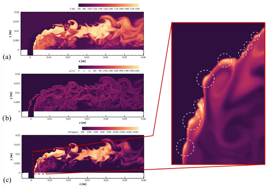
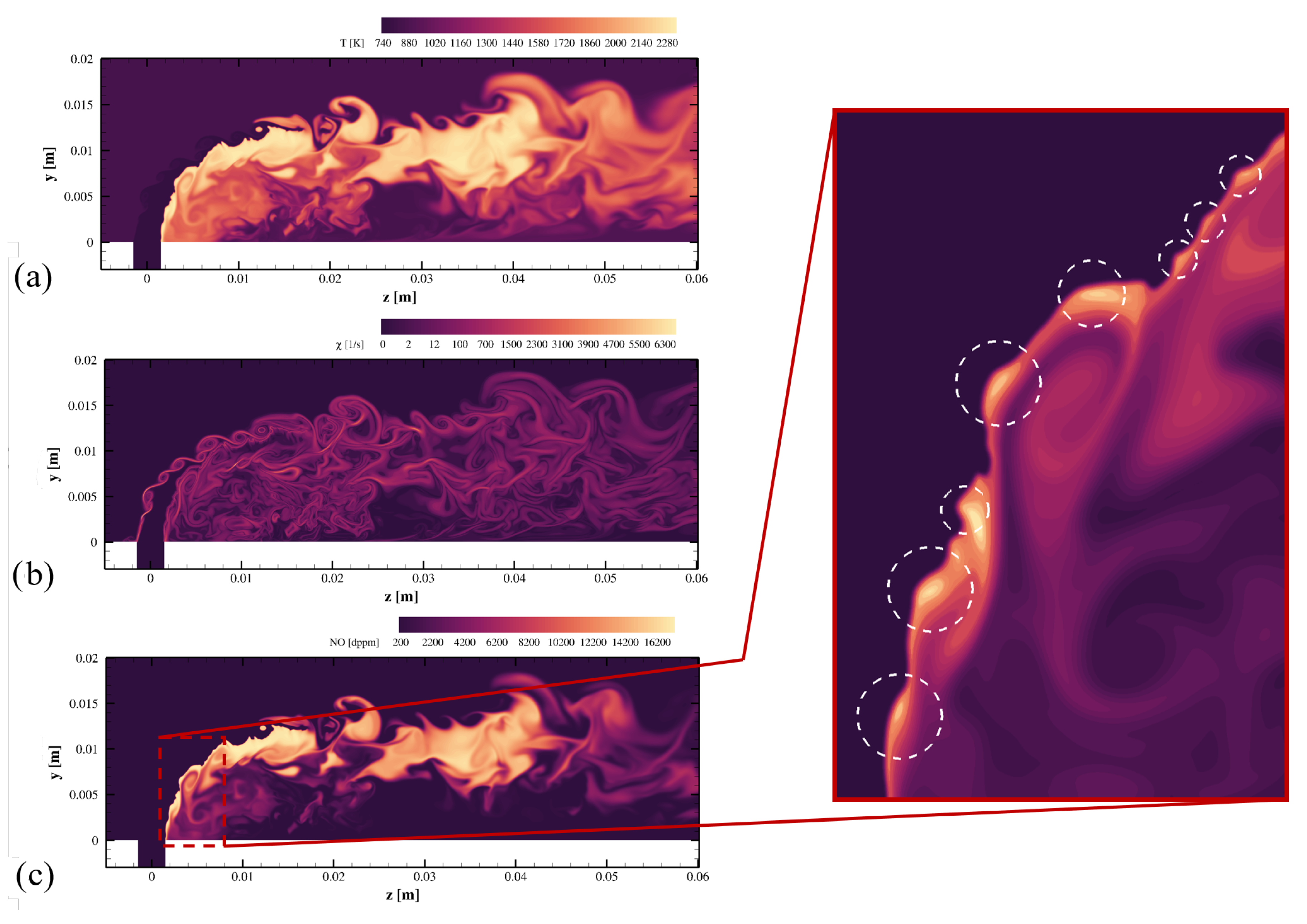
Figure 5a shows the temperature field on the plane inside the chamber. It indicates that the flame cannot anchor on the windward side of the jet, although intermittent hot spots may appear there, because the local convective time scales are too short and the strain rates too large. Stable anchoring is instead observed only inside the recirculation zone (leeward side). In the present configuration, the scalar Z, defined such that in the air stream and in the premixed reactant stream, should be interpreted primarily as a dilution variable rather than as a classical fuel–air mixture fraction. Figure 5b reports the corresponding scalar dissipation rate, defined as with , where , and denote the thermal conductivity, density and mixture specific heat, respectively. The highest values are found on the windward side of the jet, where the mixing between the dilution crossflow and the premixed reactant stream is strongest.
Figure 5.
Contours in the central longitudinal z–y plane of the instantaneous temperature (a), scalar dissipation rate (b), and NO concentration [dppm] with a zoom on the leeward side (c). The lateral inset highlights the NO-enhanced production in positive-curved flame zones (white dashed circles).
Figure 5c shows the corresponding NO distribution on the same plane, indicating that NO formation is concentrated in the hottest regions. As mixing proceeds within the chamber and the flow is convected towards the outlet, NO levels decrease markedly, reaching an average value of about 400 dppm at the exit section.
For the present NH3/H2/air configuration, a progress variable was introduced as
where the coefficients were selected such that . The corresponding chemical source term and diffusive flux can be written in compact form as
with denoting the mixture-averaged Hirschfelder diffusive flux of species k.
In order to account for local mixture stratification, the local equivalence ratio was evaluated from the elemental mass fractions of hydrogen and oxygen as
with for the present N–H–O system. The associated elemental diffusive fluxes are defined as
Accordingly, the diffusive flux of follows from the chain rule as
while the corresponding effective diffusivity is evaluated a posteriori by projecting the actual -flux onto the local -gradient,
where is a small regularization parameter.
The progress-variable normalisation is parametrised by the local equivalence ratio , rather than by the mixture fraction Z, since directly represents the local fuel–oxidiser balance controlling the attainable product state. This is important here because differential diffusion, particularly of light hydrogen-containing species, may displace the local composition from the one-dimensional mixing line between the jet and crossflow streams. As a result, Z and are not uniquely related: fluid elements with the same mixture fraction can have different equivalence ratios and hence different equilibrium values for the progress-variable normalization. The normalised progress variable was therefore defined using unburned and equilibrium reference states obtained from unstretched laminar flames parametrised by , namely
This definition preserves the sensitivity of the reaction progress to the local thermochemical state through the -dependence of both the unburned and equilibrium reference states. Here, by construction, as a direct consequence of the adopted definition of the progress variable, whereas is tabulated over the range . The lower limit corresponds to the lean flammability threshold of the mixture, while the maximum equivalence ratio found within the domain is approximately , as shown by the PDF in Figure 4b. In the homogeneous-premixing limit, and become independent of , so that the additional stratification effects vanish and the classical premixed formulation is recovered.
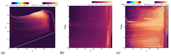
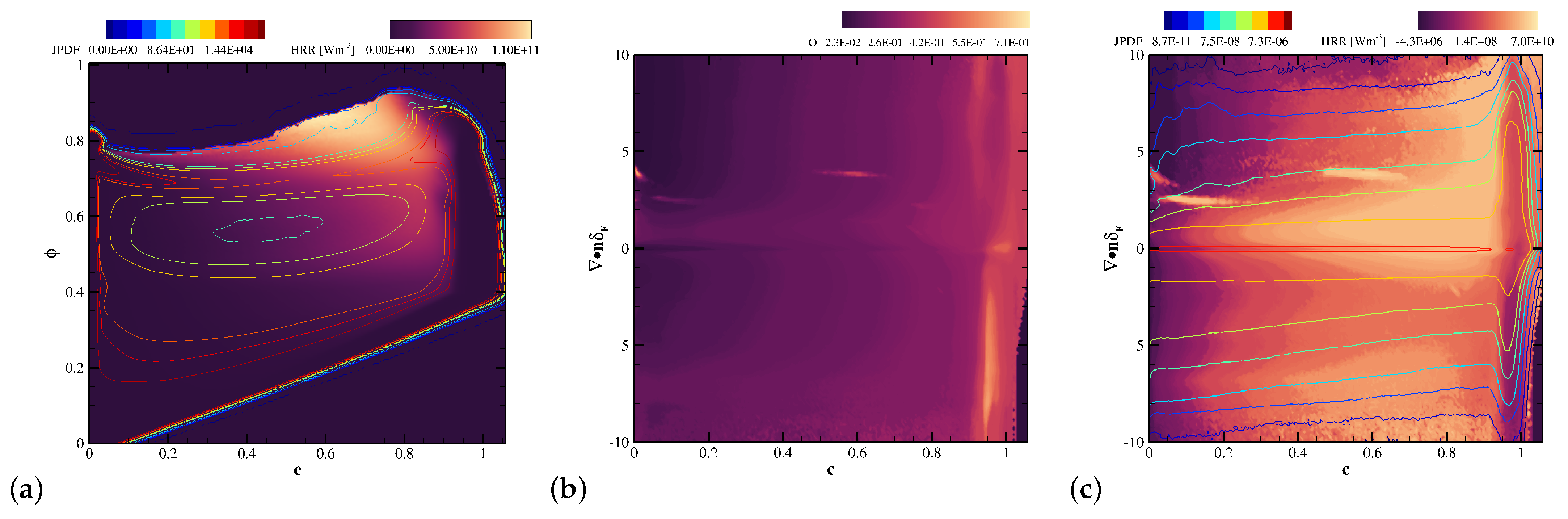
The resulting statistical behaviour of the flame is summarised in Figure 6. Figure 6a shows the mean heat release rate in the space () together with iso-contours of the joint PDF of c and . The isolines of the joint distribution in the space show that the nominal jet composition, , is mainly associated with either fresh or nearly fully reacted states, whereas intermediate progress-variable levels are preferentially sampled at leaner conditions. Since is evaluated from elemental mass fractions, this behaviour suggests that the partially reacted states do not evolve along a constant- trajectory, but are strongly affected by air entrainment and local dilution. Therefore, the most probable reaction pathway in the turbulent flame is shifted towards lower equivalence ratios during the intermediate stages of combustion. Then the figure clearly shows that the mean heat release rate retains a marked dependence on even at fixed c, indicating that the progress variable alone is not sufficient to collapse the local thermochemical state. The highest heat release is concentrated in a narrow region at high, but not fully saturated, progress levels, namely around and .
Figure 6.
Statistical characterisation of the flame in terms of the normalised progress variable and local thermochemical state: (a) mean heat release rate () in the plane with superimposed iso-contours of the joint PDF of c and ; (b) conditional mean equivalence ratio () in the plane; (c) conditional mean heat release rate () in the same plane with superimposed iso-contours of the joint PDF of c and .
Figure 6b,c provide further insight into the coupled role of flame topology and the thermochemical state. As shown in Figure 6b, the conditional mean equivalence ratio (, = , with ) is primarily organised by the progress variable, with only a weak dependence on flame-front curvature () over most of the space. This indicates that, to leading order, mixture stratification is mainly distributed along the reaction-progress coordinate, while curvature effects remain secondary except close to the fully reacted side. By contrast, Figure 6c reveals that the mean heat release rate () exhibits a much more pronounced two-dimensional structure, pointing to a substantially stronger sensitivity of the local combustion intensity to front geometry. Most importantly, the highest heat-release levels do not coincide with the most probable states identified by the joint PDF, which are instead concentrated near . This shows that the most intense burning events are associated with less populated intermediate-reacting regions of the flame brush, rather than with the statistically dominant nearly burnt states.
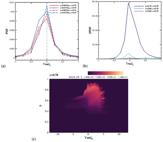
Figure 7a highlights a clear dependence of the flame-surface curvature statistics on both the streamwise location and the progress-variable level. Overall, the PDFs are negatively skewed, with the probability of negatively curved flame elements exceeding that of positively curved ones at comparable . This imbalance becomes more evident on the iso-surface (region of maximum heat release in the corresponding unstretched laminar flame), suggesting that the inner/reacted layers preferentially sample negative-curvature configurations. In contrast, the iso-surface is more strongly concentrated around small values of , indicating a larger occurrence of weakly to moderately curved elements in the outer flame region. At a fixed progress variable, moving downstream from m to m generally increases the PDF.
Figure 7.
(a) Conditional probability density function of the flame-surface curvature at fixed c and z, , for two progress-variable levels () and two streamwise locations (); (b) conditional probability density function of at fixed c and , , shown for and different equivalence-ratio levels; (c) mean heat-release rate conditioned on curvature, equivalence ratio, and progress variable, , reported for in the space.
Figure 7b shows that the isosurface is predominantly characterised by weakly curved flame elements, with the PDF becoming increasingly concentrated around as decreases. In particular, the sharp peak observed at indicates that, under leaner conditions, this isosurface is mostly associated with nearly planar flame segments. However, the conditioned mean heat-release map (see Figure 7c) reveals that the largest values of are not associated with the most probable topology alone, but are instead localized within a restricted region of the space, corresponding to moderately rich conditions and curvatures close to zero or only weakly positive. This indicates that, at , the strongest heat release is promoted primarily by the local thermochemical state, while curvature plays a secondary modulating role within a narrow range around vanishing flame-surface curvature.
3.1. Displacement Speed Analysis
The displacement speed of the iso-surface in the case of progress variable normalisation factor depending on the local equivalence ratio (or equivalently mixture fraction), can be derived as
where primes denote differentiation with respect to [49,50,51,52]. The last two terms explicitly account for local mixture inhomogeneity through the cross contribution proportional to and the scalar-dissipation contribution proportional to [53]. The present approach may therefore be regarded as the -based analogue of the two-scalar stratified-flame framework commonly formulated in terms of mixture fraction, for which the role of cross-dissipation and scalar-dissipation terms in the transport of the progress variable has been discussed extensively in the literature [54,55,56].
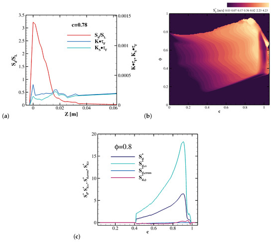
Figure 8a shows that, at , the enhancement of is highly localised around the jet centreline, corresponding to the nominal mixture. This region also exhibits the largest values of the total stretch, (; is the tangential strain; ), and of its strain-induced component, . Since remains larger than over the most active portion of the flame, the curvature-induced propagation term contributes appreciably to the local flame-surface-density source term. Away from the jet core, the displacement speed decreases, while the stretch contributions remain almost constant, indicating a much weaker influence on the net flame surface formation with respect to the inlet region.
Figure 8.
Conditional and spatial characterisation of the displacement speed: (a) spatial profiles, at , of , the total normalized stretch rate , and the strain-induced contribution along the streamwise coordinate z. The position corresponds to the centre of the fuel-mixture jet at nominal ; (b) conditional mean of the density-weighted displacement speed, , in the space (); (c) components of the density-weighted displacement speed as function of the progress variable at .
Figure 8b reports the conditional mean of the density-weighted displacement speed, , in the space (). The map shows that the largest values of are localised in the late reaction zone, approximately for , over a finite range of equivalence ratios surrounding the nominal jet composition. At lower progress-variable values, the displacement speed remains comparatively small, whereas it increases rapidly as the flame approaches the high-c region and then decreases close to the burnt side. This behaviour indicates that enhanced flame propagation is not associated with a single value of , but with a combined thermo-chemical state defined by both mixture composition and reaction progress.
The total displacement-speed budget is largely controlled by the chemical source contribution as indicated in Figure 8c at . The term increases rapidly through the reaction layer and reaches its maximum at advanced progress variable values, around , before dropping sharply towards the burnt side. The total displacement speed follows the same qualitative trend but remains much smaller than , indicating that the residual diffusive contribution provides a strong negative compensation to the chemical production of the progress variable. The stratification-related cross terms, , remain weak and slightly negative over most of the reaction layer. Similarly, the contribution associated with the diffusive flux of the equivalence ratio, , is small compared with the chemical term, although it becomes positive in the late reaction zone. Therefore, at the nominal jet equivalence ratio, the enhancement of is primarily chemically driven, while diffusion mainly acts to reduce the net displacement speed and mixture-stratification effects provide only a secondary correction.
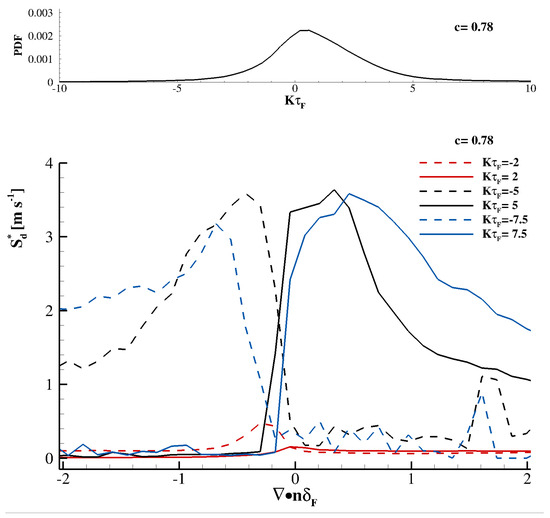
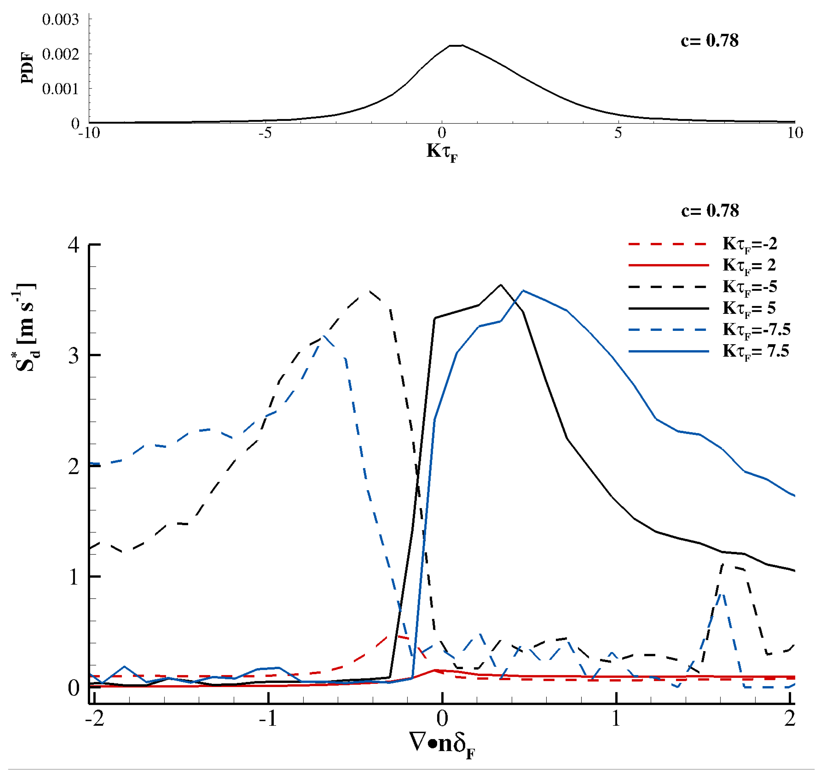
Figure 9 reports the conditional mean of the density-weighted displacement speed as a function of for selected values of the normalized stretch and at (). The curves corresponding to moderate stretch, , show relatively weak sensitivity to curvature and remain at comparatively low values of . In contrast, the response becomes much stronger for intense stretch events. For , the displacement speed increases sharply on the positive-curvature side, whereas for the largest values are shifted towards negative curvature. This approximately antisymmetric organisation with respect to the sign of the stretch suggests that the most intense propagation events are associated with flame elements for which the local geometrical configuration and the local stretch act coherently.
Figure 9.
Conditional mean of the density-weighted displacement speed, , at , as a function of normalized flame stretch and normalized curvature at three level of the normalized stretch rate (,). In the upper panel, the distribution of the normalised stretch rate () is represented at .
The marginal PDF of , shown in the upper panel of Figure 9, is strongly peaked around weakly positive stretch values and rapidly decreases towards the tails. Therefore, although the largest conditional values of occur for , these events are statistically rare. As a consequence, their contribution to the global mean displacement speed cannot be inferred from the conditional mean alone. For intense stretch events, approximately , the conditional displacement speed exhibits a clear asymmetry with respect to curvature, with larger values of over positively curved flame elements than over negatively curved ones. This indicates that, in the strong-stretch regime, the flame response is not governed solely by the magnitude of stretch, but by its coupling with flame-front geometry. Since positive curvature denotes flame elements convex towards the fresh/reacting mixture , this behaviour is consistent with a curvature-induced enhancement of diffusive transport towards the reaction layer, which favours larger local propagation speeds, particularly in the presence of light, highly diffusive fuel species.
3.2. NO Formation
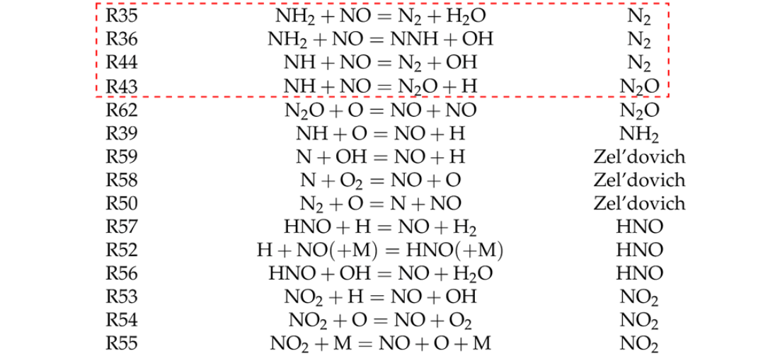
While in and hydrocarbon flames, NO is often dominated by the thermal/Zel’dovich route and therefore tends to increase progressively in the post-flame region, in ammonia flames, NO is mainly produced through fuel-nitrogen pathways, with a rapid formation in the reaction zone, followed by partial consumption downstream. As a consequence, NO mitigation in ammonia and ammonia/hydrogen flames is not governed only by flame-temperature reduction, but also by the competition between NO-forming and NO-consuming nitrogen chemistry [18,57,58,59]. During ammonia oxidation, NH3 is first converted into NH2 and NH radicals through reactions with H, O and OH. These intermediates can form NO either directly, for instance, through reactions of NHx with O/O2, or indirectly through HNO, which is known to be a major NO-producing intermediate in ammonia flames. In the present analysis, the direct NHx conversion to NO is classified as the NH2 pathway, whereas NO formation through HNO is grouped in the HNO pathway. Additional contributions arise from the Zel’dovich route, NO2 chemistry, N2O chemistry and reactions involving N2/NNH intermediates. In ammonia-containing flames, the Zel’dovich route should not be interpreted as purely thermal, since N atoms may originate not only from N2 dissociation but also from fuel-nitrogen chemistry [59,60]. Following this classification, the NO source term is decomposed into six pathways: N2, NH2, N2O, Zel’dovich, HNO and NO2. For each pathway, the contribution to NO production is obtained by summing the NO rates of production of the selected elementary reactions listed in Table 3. This pathway-based decomposition includes both NO-producing and NO-consuming reactions. In particular, the reactions involving NO consumption by NHi radicals, which lead to NNH, N2O and ultimately N2, are associated with the NO-sink process and are therefore expected to provide negative contributions to the NO source term. This approach allows the role of each pathway to be analysed in the progress-variable space and, in the present turbulent configuration, further conditioned on local mixture composition and flame topology. It is therefore well suited to identify how turbulence, differential diffusion and flame-front curvature modify the balance between fuel-nitrogen oxidation routes and NO-sink reduction mechanisms across the reaction layer and the post-flame region.
Table 3.
Synthesis of the reactions involved in the NO formation pathways. The red dashed box highlights the reactions of the NO-sink process.
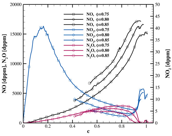
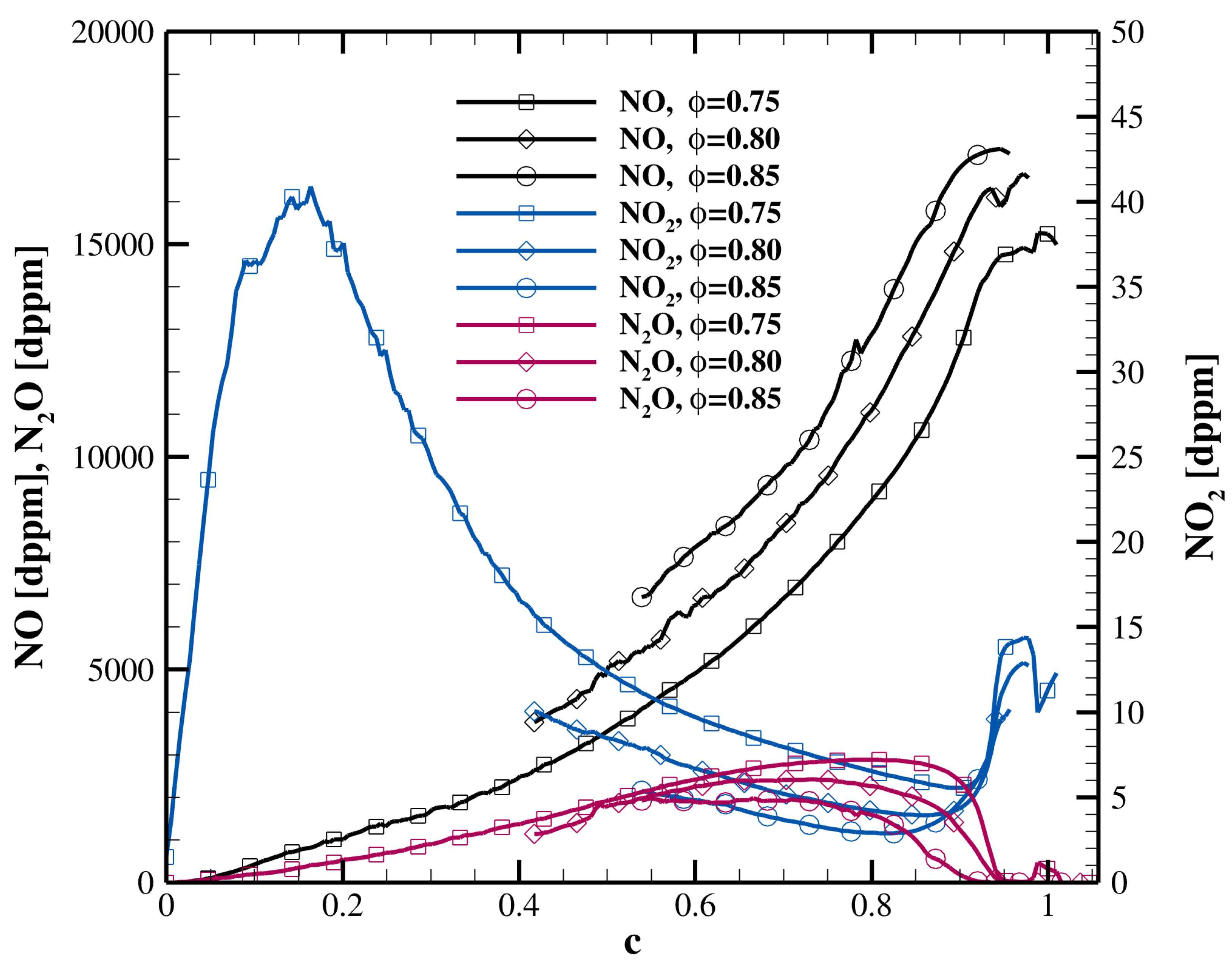
We now investigate the physical mechanisms controlling the formation of nitrogen oxide species. Figure 10 reports the conditional mean concentrations of NO, NO2 and N2O as a function of the progress variable for three representative equivalence-ratio levels, , , and . These values span the region where the two-dimensional -conditioned statistics show the largest nitrogen-oxide activity. The three species exhibit markedly different behaviours across the flame structure. NO increases almost monotonically with c and reaches its largest values in the late reaction zone, close to the burnt side. The NO level also increases with , with the richest branch, , producing the largest concentrations. This indicates that NO is mainly accumulated in advanced-reacted states, where the oxidation of nitrogen-containing intermediates becomes most effective. By contrast, N2O behaves as an intermediate species. Its concentration rises from the middle of the reaction layer, reaches a broad maximum at intermediate to high values of c, and then decreases as the flame approaches the fully burnt state. This behaviour is consistent with the role of N2O as a transient reservoir in the nitrogen chemistry: it is produced in the intermediate reaction zone, but is subsequently consumed or converted as the temperature and oxidation level increase. NO2 remains much smaller than NO and N2O and is therefore reported on a separate axis. Its largest values are found at relatively low-to-intermediate progress-variable levels, especially on the leaner branch. The rapid decrease of NO2 towards high c suggests that NO2 mainly acts as a secondary interconversion species in cooler or less advanced reaction regions, while the late reaction zone is dominated by NO accumulation. Overall, the trends show a clear separation between the three nitrogen-oxide species: NO is the final dominant product in the high-c region, N2O is an intermediate reservoir concentrated in the partially reacted layer, and NO2 is a minor species mainly associated with earlier and leaner flame states.
Figure 10.
Conditional mean concentrations of NO, NO2 and N2O as a function of the progress variable for , , and . NO and N2O are reported on the left axis, while NO2 is shown on the right axis because of its much lower concentration. The figure highlights the accumulation of NO in the late reaction zone, the intermediate-reservoir character of N2O, and the minor, early/intermediate contribution of NO2.
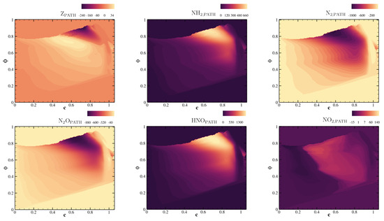
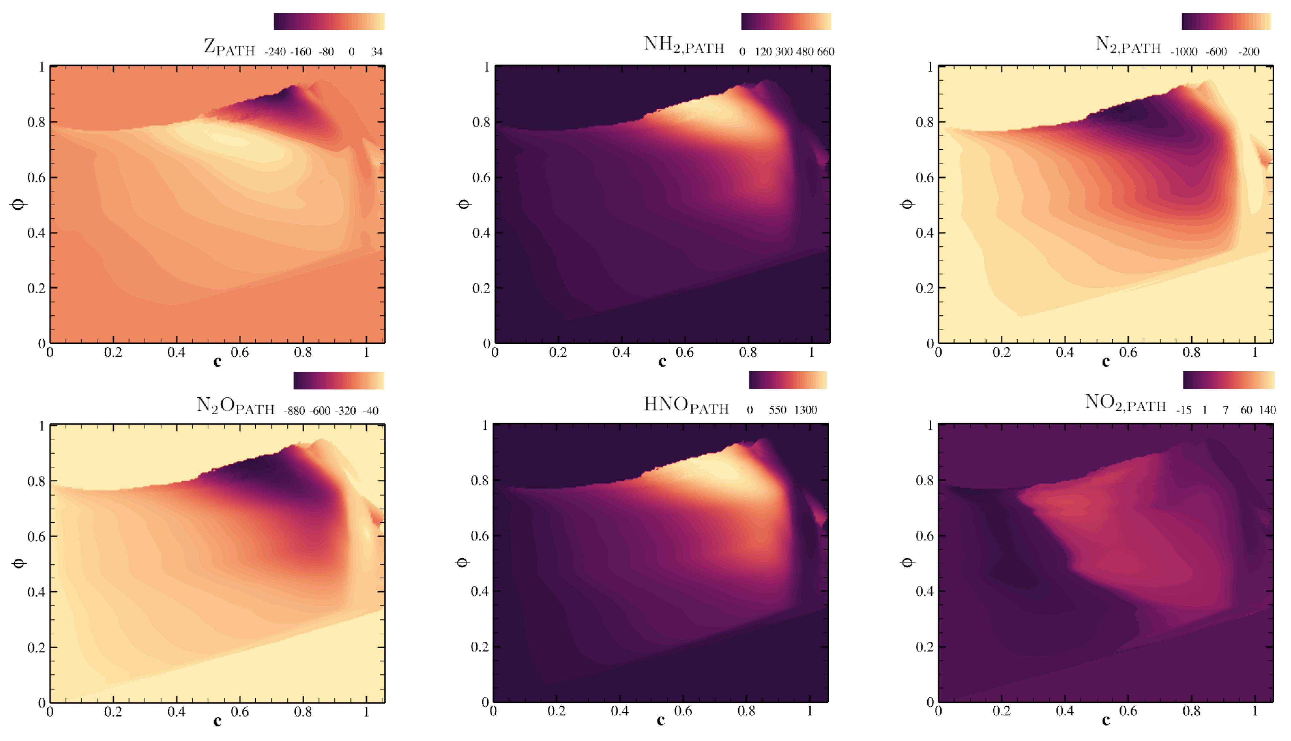
Figure 11 reports the conditional NO chemical source term in the space, decomposed into the six reaction pathways listed in Table 3. The maps show that the NO budget is governed by a localised competition between NO-forming and NO-consuming routes in the intermediate-to-late reaction zone. Among the positive contributions, the HNO and NH2 pathways provide the dominant NO production, with maxima located at advanced progress-variable values and over equivalence ratios close to the nominal jet composition. This indicates that NO formation is mainly driven by the oxidation of nitrogen-containing intermediates produced during ammonia decomposition. Conversely, the N2 and N2O pathways provide negative contributions over approximately the same region of the plane, highlighting the role of NO-sink chemistry in reducing NO through reactions involving NHx radicals. The spatial overlap between these positive and negative contributions indicates that the net NO source results from a local balance between fuel-nitrogen oxidation and NO-reduction mechanisms, rather than from a single dominant production route. The NO2 pathway exhibits a weaker but coherent contribution, mainly distributed in the intermediate reaction zone and over lean-to-near-nominal equivalence ratios, suggesting that NO2 acts primarily as a secondary interconversion channel. Finally, the Zel’dovich pathway remains comparatively small, confirming that, under the present ammonia/hydrogen combustion conditions, the NO chemistry is controlled primarily by fuel-nitrogen pathways and their competition with NO-sink reduction routes rather than by the thermal mechanism.
Figure 11.
Conditional NO chemical source term [kg/(m3s)] in the space, decomposed into the six pathways reported in Table 3. The maps show the local competition between NO-producing routes, mainly HNO and NH2, and NO-consuming pathways associated with N2 and N2O formation.
Additional conditioning on flame curvature, not reported here for brevity, shows that the most intense nitrogen-chemistry activity is preferentially associated with positively curved flame elements, mainly in the intermediate-to-late reaction zone (see the dashed white circles in the zoomed panel of Figure 5c). This behaviour is consistent with recent high-fidelity studies of ammonia/hydrogen flames, where NO formation has been shown to be strongly affected by flame-front topology, preferential diffusion and thermo-diffusive transport [19,20,61,62]. In the present case, positive curvature does not simply enhance the net formation of NO; rather, it intensifies the local competition between fuel-nitrogen oxidation routes, mainly through HNO and NHx intermediates, and NO reduction routes leading to N2 and N2O. This interpretation is supported by the pathway analysis, which identifies the HNO and NHx branches as the dominant positive NO-forming contributions, while the N2 and N2O pathways act as the main NO-consuming channels [63,64].
The dominant role of the HNO branch provides a mechanistic explanation for this curvature sensitivity. A closer inspection of the elementary reactions forming the HNO pathway shows that their largest rates are localised over positively curved flame elements, but at different equivalence-ratio levels depending on the reacting radical. The reaction
is the strongest of the HNO reactions and is favoured towards the richer side of the sampled mixture range, where the availability of H radicals and hydrogen-containing species is larger. By contrast,
is more active under slightly leaner or more oxidising conditions, where the OH pool is enhanced. The reaction
acts instead as a NO–HNO interconversion channel, indicating that HNO behaves as an active intermediate reservoir rather than as a passive product [64]. Recalling that positive curvature denotes flame elements convex towards the fresh reactants, the preferential intensification of NO chemistry can therefore be interpreted as the result of curvature-induced modifications of the local H/OH radical pool and of the diffusive supply of light reactive species. The enhanced NO source observed over the positively curved flame elements is thus not a purely thermal effect, but arises from the coupled interaction between flame geometry, preferential diffusion, local mixture enrichment, and fuel-nitrogen chemistry.
4. Conclusions
A direct numerical simulation of a lean premixed NH3/H2/N2/air jet in crossflow was performed at micro-gas-turbine-relevant pressure and inlet temperature conditions. The operating point, selected from a preliminary RANS campaign, corresponds to and , and represents a compromise between stable combustion, limited unburned fuel, reduced NO emissions, and sufficiently high outlet temperature. The DNS confirms that this configuration sustains a stable flame anchored on the leeward side of the jet, within and downstream of the recirculation region generated behind the injector, whereas the windward side is characterised by strong scalar dissipation and short convective time scales that prevent persistent flame anchoring. The flame topology is governed by the interaction between the rectangular jet and the hot air crossflow. Large Kelvin–Helmholtz structures develop in the jet shear layer, promote entrainment of crossflow air and generate a broad range of local mixture states. The volume-weighted statistics show that hot reacting regions occupy only a limited fraction of the domain, while most of the volume is filled by cold or weakly heated fluid. The joint statistics in the space further show that the reaction does not proceed along a constant- trajectory. Intermediate progress-variable states are preferentially sampled at leaner conditions than the nominal jet composition, indicating that turbulent entrainment, dilution and differential diffusion strongly affect the local thermochemical path followed by the flame.
The progress-variable and heat-release statistics show that the largest combustion intensities are localised in a restricted region of the space, approximately around and . These states are not the most probable states of the flame brush, which are instead concentrated closer to the nearly burnt side. Thus, the most intense burning events are localised in less-populated intermediate-reacting regions, where the local mixture state and flame-front geometry combine to enhance the reaction rate.
The displacement-speed analysis reveals that the largest values of the density-weighted displacement speed are concentrated near the jet centreline and shear-layer region, where total stretch and strain-induced stretch are simultaneously enhanced. The budget of is dominated by the chemical-source contribution, while the residual diffusive term mainly reduces the net propagation speed. The additional stratification-induced cross terms associated with the -dependent progress-variable normalisation remain comparatively small, with a maximum magnitude of only a few percent of the total . For intense stretch events, approximately , exhibits a clear curvature asymmetry, with larger values over positively curved flame elements. This indicates that, in the strong-stretch regime, local propagation is controlled by the coupled action of stretch, flame-front geometry and preferential diffusion, rather than by stretch magnitude alone.
The analysis of nitrogen chemistry shows that NO formation is governed mainly by fuel-nitrogen pathways. NO accumulates in the late reaction zone, N2O acts as an intermediate reservoir in the partially reacted layer, and NO2 remains a minor species mostly associated with earlier and leaner flame states. The pathway decomposition demonstrates that the HNO and NH2 routes provide the dominant positive NO source terms, whereas the N2 and N2O pathways represent the main NO-consuming channels associated with NO-sink chemistry. The Zel’dovich and NO2 pathways remain secondary under the present conditions, confirming that NO production is not controlled by a purely thermal mechanism.
Additional conditioning on flame curvature indicates that the strongest nitrogen-chemistry activity is preferentially associated with positively curved flame elements. This behaviour is consistent with the enhancement of the HNO branch, whose elementary reactions and are directly controlled by the local H/OH radical pool. Positive curvature, therefore, does not simply increase the net NO source; it intensifies the local competition between NO-forming and NO-consuming pathways by modifying the diffusive supply of light-reactive species and the local radical pool.
At the DNS outlet, the cross-sectionally averaged NO concentration is about 400 dppm. Nevertheless, extended-domain RANS computation shows that a longer residence time would further reduce the NO level, potentially below 100 dppm. Overall, the present results show that lean premixed NH3/H2/N2/air injection in a rectangular jet-in-crossflow configuration can provide stable flame anchoring and efficient fuel consumption, while the final NO level is determined by the coupled effect of mixing, residence time, fuel-nitrogen chemistry and flame-front topology.
Future DNS studies should extend the present analysis to higher-Reynolds-number conditions. A particularly useful strategy would be to increase both the crossflow and jet velocities while preserving the momentum-flux ratio J, thereby maintaining a comparable jet-penetration regime while increasing the turbulence intensity, stretch-rate levels and curvature fluctuations inside the flame brush. Such simulations would allow one to isolate the effect of Reynolds number from the gross jet trajectory, and to assess whether the curvature-controlled enhancement of displacement speed and nitrogen chemistry observed here persists, weakens or becomes amplified at higher stretch and stronger flame-front wrinkling.
Author Contributions
D.C., M.C. and E.G.: original draft preparation and writing; D.C. and M.C.: fluid dynamic simulation and interpretation of the results; E.G.: supervision of the project, interpretation of the results and revision of the manuscript. All authors have read and agreed to the published version of the manuscript.
Funding
This study was performed within the Italian project “RICERCA E SVILUPPO DI TECNOLOGIE PER LA FILIERA DELL’IDROGENO POR-H2” (“Research and Development of Technologies for Hydrogen Chain”, POR-H2, WP2, LA2.2.5), funded by the European Union (NextGenerationEU) through the Italian Ministry of Environment and Energy Security, under the National Recovery and Resilience Plan (PNRR, Mission 2, Component 2, Investment 3.5, project code I83C22001170006).
Data Availability Statement
The original contributions presented in this study are included in the article. Further inquiries can be directed to the corresponding author.
Acknowledgments
The computational resources and associated technical support utilised for this study were made available by the CRESCO/ENEAGRID High-Performance Computing infrastructure and its staff [39]. This computing infrastructure is funded by ENEA, the Italian National Agency for New Technologies, Energy, and Sustainable Economic Development, along with contributions from Italian and European research programmes (visit http://www.cresco.enea.it/english, accessed on 20 October 2023).
Conflicts of Interest
The authors declare no conflicts of interest.
Nomenclature
| Roman symbols | |
| Elemental mass fraction of element i | |
| Elemental mass fraction of carbon | |
| Elemental mass fraction of hydrogen | |
| Elemental mass fraction of oxygen | |
| Coefficient used in the definition of the progress variable | |
| c | Normalised progress variable |
| Mixture specific heat at constant pressure, [J kg−1 K−1] | |
| D | Thermal diffusivity, , [m2 s−1] |
| Effective diffusivity of the local equivalence ratio, [m2 s−1] | |
| Conditional probability density function of curvature at fixed c and z | |
| Conditional probability density function of curvature at fixed and c | |
| Conditional probability density function of normalised stretch at fixed c | |
| Heat release rate, [W m−3] | |
| J | Momentum-flux ratio |
| Diffusive flux of species k, [kg m−2 s−1] | |
| Elemental diffusive flux of element i, [kg m−2 s−1] | |
| Diffusive flux of the local equivalence ratio, [kg m−2 s−1] | |
| Diffusive flux of the progress variable, [kg m−2 s−1] | |
| k | Thermal conductivity, [W m−1 K−1] |
| K | Total flame stretch rate, , [s−1] |
| Tangential strain contribution to flame stretch, , [s−1] | |
| l | Reference injector dimension, [m] |
| Computational-domain length in the streamwise direction, [m] | |
| Computational-domain length in the wall-normal direction, [m] | |
| Computational-domain length in the spanwise direction, [m] | |
| M | Third body in elementary reactions |
| Flame-front normal vector, | |
| Number of species used in the progress-variable definition | |
| Number of chemical species | |
| Number of grid points in the streamwise direction | |
| Number of grid points in the wall-normal direction | |
| Number of grid points in the spanwise direction | |
| p | Pressure, [Pa] |
| Volume-weighted probability density function | |
| q | Generic scalar quantity |
| r | Velocity ratio between jet and crossflow |
| Reynolds number | |
| Turbulent Reynolds number | |
| Displacement speed, [m s−1] | |
| Density-weighted displacement speed, , [m s−1] | |
| Chemical-source contribution to displacement speed, [m s−1] | |
| Diffusive-flux contribution associated with , [m s−1] | |
| Cross-scalar contribution proportional to , [m s−1] | |
| Scalar-dissipation contribution proportional to , [m s−1] | |
| Unstretched laminar flame speed, [m s−1] | |
| t | Time, [s] |
| T | Temperature, [K] |
| Maximum flame temperature, [K] | |
| Unburned-gas temperature, [K] | |
| Velocity vector, [m s−1] | |
| Crossflow freestream velocity, [m s−1] | |
| Nomenclature–continued | |
| Jet velocity, [m s−1] | |
| Volume of computational cell n, [m3] | |
| Atomic or molecular weight of element/species i, [kg kmol−1] | |
| Molecular weight of species k, [kg kmol−1] | |
| x | Cartesian coordinate; spanwise direction in the present domain, [m] |
| y | Cartesian coordinate; wall-normal direction in the present domain, [m] |
| z | Cartesian coordinate; streamwise direction in the present domain, [m] |
| Mass fraction of species i | |
| Mass fraction of species k | |
| Z | Dilution scalar; in the air stream and in the premixed reactant stream |
| Dimensionless wall distance | |
| Greek symbols | |
| Number of atoms of element i in species k | |
| Flame-front thickness, , [m] | |
| Time step, [s] | |
| Progress-variable normalisation factor, | |
| Regularisation parameter used in the evaluation of | |
| Kolmogorov length scale of the crossflow, [m] | |
| Kolmogorov length scale of the jet, [m] | |
| Flame-front curvature, , [m−1] | |
| Dynamic viscosity, [kg m−1 s−1] | |
| Density, [kg m−3] | |
| Unburned-gas density, [kg m−3] | |
| Flame time scale, , [s] | |
| Local equivalence ratio | |
| Global equivalence ratio obtained by mixing the fuel jet and the air crossflow | |
| Nominal equivalence ratio of the injected premixed fuel mixture | |
| Scalar dissipation rate of Z, , [s−1] | |
| Progress variable | |
| Unburned reference value of the progress variable | |
| Equilibrium reference value of the progress variable | |
| Chemical source term of species k, [kg m−3 s−1] | |
| Chemical source term of the progress variable, [kg m−3 s−1] | |
| Operators, averages and notation | |
| ∇ | Gradient operator |
| Divergence operator | |
| Tangential divergence operator along the flame surface | |
| Euclidean norm or absolute value | |
| Conditional mean of q at fixed variables a and b | |
| Conditional mean of q at fixed variables a, b and c | |
| Derivative with respect to | |
| Second derivative with respect to | |
| Subscripts and superscripts | |
| Crossflow | |
| Effective quantity | |
| Equilibrium state | |
| G | Global quantity |
| i | Generic element or species index |
| Nomenclature–continued | |
| j | Jet quantity |
| k | Generic species index |
| N | Nominal quantity |
| u | Unburned state |
| Chemical-source contribution | |
| Quantity associated with the local equivalence ratio | |
References
- Yao, N.; Pan, W.; Zhang, J.; Wei, L. The advancement on carbon-free ammonia fuels for gas turbine: A review. Energy Convers. Manag. 2024, 315, 118745. [Google Scholar] [CrossRef] [Scilit]
- Pfahl, U.; Ross, M.; Shepherd, J.; Pasamehmetoglu, K.; Unal, C. Flammability limits, ignition energy, and flame speeds in H2–CH4–NH3–N2O–O2–N2 mixtures. Combust. Flame 2000, 123, 140–158. [Google Scholar]
- Mathieu, O.; Petersen, E.L. Experimental and modeling study on the high-temperature oxidation of Ammonia and related NOx chemistry. Combust. Flame 2015, 162, 554–570. [Google Scholar] [CrossRef] [Scilit]
- Hayakawa, A.; Arakawa, Y.; Mimoto, R.; Somarathne, K.K.A.; Kudo, T.; Kobayashi, H. Experimental investigation of stabilization and emission characteristics of ammonia/air premixed flames in a swirl combustor. Int. J. Hydrogen Energy 2017, 42, 14010–14018. [Google Scholar] [CrossRef] [Scilit]
- Khateeb, A.A.; Guiberti, T.F.; Wang, G.; Boyette, W.R.; Younes, M.; Jamal, A.; Roberts, W.L. Stability limits and NO emissions of premixed swirl ammonia-air flames enriched with hydrogen or methane at elevated pressures. Int. J. Hydrogen Energy 2021, 46, 11969–11981. [Google Scholar] [CrossRef] [Scilit]
- Khateeb, A.A.; Guiberti, T.F.; Zhu, X.; Younes, M.; Jamal, A.; Roberts, W.L. Stability limits and NO emissions of technically-premixed ammonia-hydrogen-nitrogen-air swirl flames. Int. J. Hydrogen Energy 2020, 45, 22008–22018. [Google Scholar] [CrossRef] [Scilit]
- Normand, A. Method for Generating a Reducing Atmosphere for Heat-Treating Installations. US Patent 4,069,071, 17 January 1978. [Google Scholar]
- Ganley, J.C.; Seebauer, E.G.; Masel, R.I. Development of a microreactor for the production of hydrogen from ammonia. J. Power Sources 2004, 137, 53–61. [Google Scholar] [CrossRef] [Scilit]
- Sørensen, R.Z.; Nielsen, L.J.; Jensen, S.; Hansen, O.; Johannessen, T.; Quaade, U.; Christensen, C.H. Catalytic ammonia decomposition: Miniaturized production of COx-free hydrogen for fuel cells. Catal. Commun. 2005, 6, 229–232. [Google Scholar]
- Valera-Medina, A.; Marsh, R.; Runyon, J.; Pugh, D.; Beasley, P.; Hughes, T.; Bowen, P. Ammonia–methane combustion in tangential swirl burners for gas turbine power generation. Appl. Energy 2017, 185, 1362–1371. [Google Scholar] [CrossRef] [Scilit]
- Karim, H.; Natarajan, J.; Narra, V.; Cai, J.; Rao, S.; Kegley, J.; Citeno, J. Staged combustion system for improved emissions operability and flexibility for 7HA class heavy duty gas turbine engine. In Proceedings of the ASME Turbo Expo 2017: Turbomachinery Technical Conference and Exposition, Charlotte, NC, USA, 26–30 June 2017. [Google Scholar]
- Pennell, D.A.; Bothien, M.R.; Ciani, A.; Granet, V.; Singla, G.; Thorpe, S.; Wickstroem, A.; Oumejjoud, K.; Yaquinto, M. An introduction to the ansaldo GT36 constant pressure sequential combustor. In Proceedings of the ASME Turbo Expo 2017: Turbomachinery Technical Conference and Exposition, Charlotte, NC, USA, 26–30 June 2017. [Google Scholar]
- Goh, E.; Sirignano, M.; Li, J.; Nair, V.; Emerson, B.; Lieuwen, T.; Seitzman, J. Prediction of Minimum Achievable NOx Levels for Fuel-Staged Combustors. Combust. Flame 2019, 200, 276–285. [Google Scholar] [CrossRef] [Scilit]
- Otero, M.; Genova, T., Jr.; Stiehl, B.; Morales, A.J.; Martin, S.; Ahmed, K.A. The Influence of Pressure on Flame-Flow Characteristics of a Reacting Jet in Crossflow. ASME J. Energy Res. Technol. 2021, 144, 052301. [Google Scholar] [CrossRef] [Scilit]
- Stiehl, B.; Otero, M.; Genova, T.; Martin, S.; Ahmed, K. The Effect of Pressure on NOx Entitlement and Reaction Timescales in a Premixed Axial Jet-In-Crossflow. ASME J. Energy Res. Technol. 2021, 143, 112306. [Google Scholar] [CrossRef] [Scilit]
- Lieuwen, T.; Chang, M.; Amato, A. Stationary Gas Turbine Combustion: Technology Needs and Policy Considerations. Combust. Flame 2021, 160, 1311–1314. [Google Scholar]
- Alnasif, A.; Mashruk, S.; Shi, H.; Alnajideen, M.; Wang, P.; Pugh, D.; Valera-Medina, A. Evolution of ammonia reaction mechanisms and modeling parameters: A review. Appl. Energy Combust. Sci. 2023, 15, 100175. [Google Scholar] [CrossRef] [Scilit]
- Elbaz, A.M.; Wang, S.; Guiberti, T.F.; Roberts, W.L. Review on the recent advances on ammonia combustion from the fundamentals to the applications. Fuel Commun. 2022, 10, 100053. [Google Scholar] [CrossRef] [Scilit]
- Rieth, M.; Gruber, A.; Chen, J.H. A direct numerical simulation study on NO and N2O formation in turbulent premixed ammonia/hydrogen/nitrogen-air flames. Proc. Combust. Inst. 2023, 39, 2279–2288. [Google Scholar] [CrossRef] [Scilit]
- Karimkashi, S.; Tamadonfar, P.; Kaario, O.; Vuorinen, V. A Numerical Investigation on Effects of Hydrogen Enrichment and Turbulence on NO Formation Pathways in Premixed Ammonia/Air Flames. Combust. Sci. Technol. 2023, 197, 77–106. [Google Scholar] [CrossRef] [Scilit]
- Tian, T.; Wang, H.; Chen, J.H.; Li, Z.; Aldén, M.; Luo, K.; Fan, J. Direct numerical simulations of laboratory-scale NH3/air jet flames: Analysis of flame structure, flame stabilization and NO emission characteristics. Combust. Flame 2025, 274, 114007. [Google Scholar]
- Cecere, D.; Cimini, M.; Carpenella, S.; Giacomazzi, E. HIGH PRESSURE DIRECT NUMERICAL SIMULATION OF TURBULENT PREMIXED NH3/H2/N2–AIR SLOT FLAME AT HIGH EQUIVALENCE RATIO. In High Performance Computing on CRESCO Infrastructure: Research Activities and Results 2023; ENEA (Italian National Agency for New Technologies, Energy and Sustainable Development): Rome, Italy, 2024; p. 41. [Google Scholar]
- Giacomazzi, E.; Cecere, D.; Cimini, M.; Carpenella, S. Direct Numerical Simulation of a Reacting Turbulent Hydrogen/Ammonia/Nitrogen Jet in an Air Crossflow at 5 Bar. Energies 2023, 16, 7704. [Google Scholar] [CrossRef] [Scilit]
- Cecere, D.; Cimini, M.; Carpenella, S.; Caldarelli, J.; Giacomazzi, E. Composition and Injection Angle Effects on Combustion of an NH3/H2/N2 Jet in an Air Crossflow. Energies 2024, 17, 5032. [Google Scholar] [CrossRef] [Scilit]
- Cecere, D.; Giacomazzi, E. An immersed volume method for large eddy simulation of compressible flows using a staggered-grid approach. Comput. Methods Appl. Mech. Eng. 2014, 280, 1–27. [Google Scholar] [CrossRef] [Scilit]
- Mahmood, M.; Martini, A.; Massardo, A.F.; De Paepe, W. Model based diagnostics of AE-T100 micro humid air turbine cycle. In Proceedings of the Turbo Expo: Power for Land, Sea, and Air, Oslo, Norway, 11–15 June 2018; American Society of Mechanical Engineers: New York, NY, USA, 2018; p. V003T06A008. [Google Scholar]
- Hirschfelder, J.O.; Curtiss, C.F.; Bird, R.B. The Molecular Theory of Gases and Liquids; John Wiley & Sons: Hoboken, NJ, USA, 1964. [Google Scholar]
- Ern, A.; Giovangigli, V. Multicomponent Transport Algorithms; Springer Science & Business Media: Berlin/Heidelberg, Germany, 1994; Volume 24. [Google Scholar]
- Ern, A.; Giovangigli, V. Fast and accurate multicomponent transport property evaluation. J. Comput. Phys. 1995, 120, 105–116. [Google Scholar] [CrossRef] [Scilit]
- Wilke, C.R. A viscosity equation for gas mixtures. J. Chem. Phys. 1950, 18, 517–519. [Google Scholar] [CrossRef] [Scilit]
- Bird, R.; Stewart, W.; Lightfoot, E. Transport Phenomena, 2nd ed.; John Wiley & Sons, Inc.: New York, NY, USA, 2006. [Google Scholar]
- Mathur, S.; Tondon, P.; Saxena, S. Thermal conductivity of binary, ternary and quaternary mixtures of rare gases. Mol. Phys. 1967, 12, 569–579. [Google Scholar] [CrossRef] [Scilit]
- Jiang, Y.; Gruber, A.; Seshadri, K.; Williams, F. An updated short chemical-kinetic nitrogen mechanism for carbon-free combustion applications. Int. J. Energy Res. 2020, 44, 795–810. [Google Scholar]
- Valera-Medina, A.; Amer-Hatem, F.; Azad, A.K.; Dedoussi, I.C.; de Joannon, M.; Fernandes, R.X.; Glarborg, P.; Hashemi, H.; He, X.; Mashruk, S.; et al. Review on Ammonia as a Potential Fuel: From Synthesis to Economics. Energy Fuels 2021, 35, 6964–7029. [Google Scholar] [CrossRef] [Scilit]
- Giacomazzi, E.; Cecere, D. A combustion regime-based model for large eddy simulation. Energies 2021, 14, 4934. [Google Scholar] [CrossRef] [Scilit]
- Giacomazzi, E.; Cecere, D.; Arcidiacono, N. Flame Anchoring of an H2/O2 Non-Premixed Flamewith O2 Transcritical Injection. Aerospace 2022, 9, 707. [Google Scholar]
- Cecere, D.; Giacomazzi, E.; Arcidiacono, N. DNS of a non-premixed CH4/O2 flame in a supercritical CO2 environment. Fuel 2024, 362, 130709. [Google Scholar]
- Cecere, D.; Giacomazzi, E.; Arcidiacono, N.; Picchia, F. Direct numerical simulation of a turbulent lean premixed CH4/H2–Air slot flame. Combust. Flame 2016, 165, 384–401. [Google Scholar]
- Ponti, G.; Palombi, F.; Abate, D.; Ambrosino, F.; Aprea, G.; Bastianelli, T.; Beone, F.; Bertini, R.; Bracco, G.; Caporicci, M.; et al. The role of medium size facilities in the HPC ecosystem: The case of the new CRESCO4 cluster integrated in the ENEAGRID infrastructure. In Proceedings of the 2014 International Conference on High Performance Computing & Simulation (HPCS), Bologna, Italy, 21–25 July 2014; pp. 1030–1033. [Google Scholar]
- Liou, M.S. A sequel to AUSM, Part II: AUSM+-up for all speeds. J. Comput. Phys. 2006, 214, 137–170. [Google Scholar] [CrossRef] [Scilit]
- Rudy, D.H.; Strikwerda, J.C. Boundary conditions for subsonic compressible Navier-Stokes calculations. Comput. Fluids 1981, 9, 327–338. [Google Scholar] [CrossRef] [Scilit]
- Thompson, K.W. Time dependent boundary conditions for hyperbolic systems. J. Comput. Phys. 1987, 68, 1–24. [Google Scholar] [CrossRef] [Scilit]
- Poinsot, T.J.; Lelef, S. Boundary conditions for direct simulations of compressible viscous flows. J. Comput. Phys. 1992, 101, 104–129. [Google Scholar] [CrossRef] [Scilit]
- Baum, M.; Poinsot, T.; Thévenin, D. Accurate boundary conditions for multicomponent reactive flows. J. Comput. Phys. 1995, 116, 247–261. [Google Scholar] [CrossRef] [Scilit]
- Sutherland, J.C.; Kennedy, C.A. Improved boundary conditions for viscous, reacting, compressible flows. J. Comput. Phys. 2003, 191, 502–524. [Google Scholar] [CrossRef] [Scilit]
- Klein, M.; Sadiki, A.; Janicka, J. A digital filter based generation of inflow data for spatially developing direct numerical or large eddy simulations. J. Comput. Phys. 2003, 186, 652–665. [Google Scholar] [CrossRef] [Scilit]
- Mahesh, K. The interaction of jets with crossflow. Annu. Rev. Fluid Mech. 2013, 45, 379–407. [Google Scholar] [CrossRef] [Scilit]
- Salewski, M.; Stankovic, D.; Fuchs, L. Mixing in circular and non-circular jets in crossflow. Flow Turbul. Combust. 2008, 80, 255–283. [Google Scholar]
- Echekki, T.; Chen, J.H. Analysis of the contribution of curvature to premixed flame propagation. Combust. Flame 1999, 118, 308–311. [Google Scholar] [CrossRef] [Scilit]
- Bray, K.N.C.; Domingo, P.; Vervisch, L. Role of the progress variable in models for partially premixed turbulent combustion. Combust. Flame 2005, 141, 431–437. [Google Scholar] [CrossRef] [Scilit]
- Domingo, P.; Vervisch, L.; Bray, K.N.C. Partially premixed flamelets in LES of nonpremixed turbulent combustion. Combust. Theory Model. 2002, 6, 529–551. [Google Scholar] [CrossRef] [Scilit]
- Favier, V.; Vervisch, L. Edge flames and partially premixed combustion in diffusion flame quenching. Combust. Flame 2001, 125, 788–803. [Google Scholar] [CrossRef] [Scilit]
- Brearley, P.; Ahmed, U.; Chakraborty, N. A Priori Direct Numerical Simulation Analysis of the Closure of Cross-Scalar Dissipation Rate of Reaction Progress Variable and Mixture Fraction in Turbulent Stratified Flames. Flow Turbul. Combust. 2022, 109, 351–382. [Google Scholar] [CrossRef] [Scilit]
- Lipatnikov, A.N. Stratified turbulent flames: Recent advances in understanding the influence of mixture inhomogeneities on premixed combustion and modeling challenges. Prog. Energy Combust. Sci. 2017, 62, 87–132. [Google Scholar] [CrossRef] [Scilit]
- Malkeson, S.P.; Chakraborty, N. Statistical analysis of displacement speed in turbulent stratified flames: A direct numerical simulation study. Combust. Sci. Technol. 2010, 182, 1841–1883. [Google Scholar] [CrossRef] [Scilit]
- Hesse, H.; Malkeson, S.P.; Chakraborty, N. Displacement speed statistics for stratified mixture combustion in an igniting turbulent planar jet. J. Eng. Gas Turbines Power 2012, 134, 051502. [Google Scholar] [CrossRef] [Scilit]
- CORREA, S.M. A Review of NOx Formation Under Gas-Turbine Combustion Conditions. Combust. Sci. Technol. 1993, 87, 329–362. [Google Scholar] [CrossRef] [Scilit]
- Trisjono, P.; Pitsch, H. A direct numerical simulation study on NO formation in lean premixed flames. Proc. Combust. Inst. 2017, 36, 2033–2043. [Google Scholar] [CrossRef] [Scilit]
- Kobayashi, H.; Hayakawa, A.; Somarathne, K.; Okafor, E. Science and technology of ammonia combustion. Proc. Combust. Inst. 2019, 37, 109–133. [Google Scholar] [CrossRef] [Scilit]
- Lindstedt, R.P.; Lockwood, F.C.; Selim, M.A. Detailed Kinetic Modelling of Chemistry and Temperature Effects on Ammonia Oxidation. Combust. Sci. Technol. 1994, 99, 253–276. [Google Scholar] [CrossRef] [Scilit]
- Netzer, C.; Ahmed, A.; Gruber, A.; Lovas, T. Curvature effects on NO formation in wrinkled laminar ammonia/hydrogen/nitrogen-air premixed flames. Combust. Flame 2021, 232, 111520. [Google Scholar] [CrossRef] [Scilit]
- Chi, C.; Han, W.; Thevenin, D. Effects of molecular diffusion modeling on turbulent premixed NH3/H2/air flames. Proc. Combust. Inst. 2023, 39, 2259–2268. [Google Scholar] [CrossRef] [Scilit]
- D’Alessio, F.; Lapenna, P.E.; Bottari, S.; Creta, F. Intrinsically unstable hydrogen-enriched premixed ammonia flames: Analysis and modeling of NO formation. Proc. Combust. Inst. 2024, 40, 105485. [Google Scholar] [CrossRef] [Scilit]
- Mashruk, S.; Shi, H.; Mazzotta, L.; Ustun, C.E.; Aravind, B.; Meloni, R.; Alnasif, A.; Boulet, E.; Jankowski, R.; Yu, C.; et al. Perspectives on NOx Emissions and Impacts from Ammonia Combustion Processes. Energy Fuels 2024, 38, 19253–19292. [Google Scholar] [CrossRef] [Scilit] [PubMed]

Disclaimer/Publisher’s Note: The statements, opinions and data contained in all publications are solely those of the individual author(s) and contributor(s) and not of MDPI and/or the editor(s). MDPI and/or the editor(s) disclaim responsibility for any injury to people or property resulting from any ideas, methods, instructions or products referred to in the content. |
© 2026 by the authors. Licensee MDPI, Basel, Switzerland. This article is an open access article distributed under the terms and conditions of the Creative Commons Attribution (CC BY) license.