


Abstract
To address heat accumulation, localized hot spots, and non-uniform temperature distribution in large-capacity lithium iron phosphate energy storage battery modules under high ambient temperature and high-rate charge/discharge conditions, this study proposes a fin-enhanced phase change material (PCM)-air hybrid thermal management structure for a 100 Ah prismatic lithium iron phosphate battery and a 2P18S energy storage battery module. First, the battery thermal model is validated using single-cell experimental data reported in the literature. Subsequently, a three-dimensional transient fluid–solid coupled heat transfer model is established by considering transient battery heat generation, PCM solid–liquid phase change, air-side flow and heat transfer, and temperature-dependent thermophysical properties. User-defined functions are employed to implement the transient heat source and temperature-dependent material properties. Under identical boundary conditions, the thermal management performances of three configurations, namely Fin-Air, PCM-Air, and Fin-PCM-Air, are compared. The effects of ambient temperature (20 °C, 25 °C, and 30 °C) and inlet air velocity (1 m/s, 2 m/s, and 3 m/s) on the maximum module temperature, temperature uniformity, PCM liquid fraction evolution, and flow field distribution are quantitatively analyzed. The results show that, compared with the Fin–Air system without PCM and the PCM-Air system without fins, the Fin-PCM-Air configuration reduces the maximum module temperature by 1.57% and 0.25%, respectively, at an ambient temperature of 30 °C and an inlet air velocity of 3 m/s. After four charge–discharge cycles, the peak maximum temperature of the module is approximately 38.56 °C, and the peak maximum temperature difference remains below 3.6 K, indicating good temperature uniformity and latent heat buffering capability. In addition, the air velocity trade-off analysis indicates that increasing the inlet air velocity can improve cooling performance but also increases the air-channel pressure drop and fan power consumption. Therefore, the Fin-PCM-Air structure is more suitable for high-thermal-load conditions, and its practical application should comprehensively consider cooling benefits, additional mass, manufacturing cost, and long-term reliability. This study provides a reference for the design and engineering application of hybrid thermal management structures for large-capacity energy storage battery modules.
1. Introduction
With the continuous expansion of renewable energy integration and the rapid growth of grid-side energy storage demand, electrochemical energy storage systems have become essential technical equipment for supporting the safe and stable operation of new power systems. Among various energy storage battery systems, lithium iron phosphate batteries have been widely used in large-scale energy storage stations and distributed energy storage systems because of their relatively high thermal stability, long cycle life, low material cost, and environmental friendliness [1]. However, during practical operation, electrochemical reaction heat, ohmic heat, and polarization heat jointly constitute the main internal heat sources of batteries. In particular, under high-rate charge/discharge, high ambient temperature, and long-term continuous operation conditions, the battery heat generation rate increases significantly, which can lead to heat accumulation inside the module, localized hot spots, and aggravated temperature non-uniformity among cells. If the generated heat cannot be dissipated effectively and in time, battery aging and capacity degradation will be accelerated, thereby reducing the cycle life of the system. Under extreme operating conditions, the risk of thermal runaway initiation may also increase, threatening the operational safety of energy storage systems [2]. Previous studies have shown that the suitable operating temperature of lithium-ion batteries is generally within the range of 20–40 °C [3,4], and the maximum temperature difference among cells in a battery module should preferably be controlled within 5 °C [5]. Therefore, developing efficient, reliable, and low-energy-consumption battery thermal management technologies to reduce module heat accumulation, improve temperature uniformity, and enhance temperature control capability under high-thermal-load conditions is critical for ensuring the safe, long-life, and economical operation of energy storage systems.
At present, based on the heat transfer medium and heat transfer mode, battery thermal management technologies are mainly categorized as air cooling, liquid cooling, phase change material cooling, and heat pipe cooling [6]. Among them, PCM cooling has gradually become an important research direction in battery thermal management because of its compact structure, no additional energy consumption, and good temperature equalization capability [7]. PCMs can absorb a large amount of latent heat during the solid–liquid phase change process, thereby buffering the transient thermal shock during battery charge and discharge. However, conventional organic PCMs usually have low thermal conductivity. Under high-rate charge/discharge or high heat flux conditions, their internal thermal diffusion capability is limited, which may lead to increased conductive thermal resistance, insufficient heat release, and local heat accumulation in the later stage of phase change [8]. In contrast, air cooling systems are characterized by a simple structure, low cost, light weight, and convenient maintenance, but their cooling capacity is often limited in high-power-density and large-capacity energy storage modules owing to the low volumetric heat capacity and convective heat transfer coefficient of air [9]. Therefore, a single cooling strategy is usually insufficient to simultaneously meet the requirements of efficient heat dissipation, temperature uniformity, low energy consumption, and compact structure. Hybrid thermal management combining air cooling and PCM cooling has thus attracted increasing attention [10]. In recent years, extensive studies have been conducted on PCM-Air hybrid cooling, fin-enhanced PCM, high-thermal-conductivity composite PCMs, and multifunctional battery thermal management systems. Umer Iqbal et al. [11] compared the effects of active and passive cooling strategies on the thermal behavior of lithium-ion batteries and found that both forced air cooling and PCM cooling can effectively reduce the battery temperature rise under high-rate discharge conditions, while hybrid thermal management systems can further improve the overall heat dissipation performance of battery packs. Gu et al. [12] designed a battery thermal management system integrating composite PCMs, forced air cooling, and fins, which reduced the overall system mass while satisfying the heat dissipation requirement. He et al. [13] prepared a composite PCM using expanded graphite, copper foam, and paraffin. Their cyclic charge–discharge tests showed that the maximum temperature of the battery pack could be controlled below 48 °C and the maximum temperature difference remained below 3.9 K. In addition to incorporating high-thermal-conductivity fillers into PCMs, structural enhancement is also an effective method to improve the heat transfer rate of PCMs [14]. Shen et al. [15] proposed a spider-web-like finned PCM battery thermal management system and analyzed its heat dissipation performance under an 8C high-rate discharge condition. Qin et al. [16] developed a hybrid battery thermal management system coupling forced air convection with PCMs under a 4C discharge condition. Yu et al. [17] investigated a copper foam–paraffin composite PCM combined with air cooling, and their results showed that the system could reduce battery surface temperature and promote phase change recovery of the PCM. Xue et al. [18] proposed a multifunctional thermal management system integrating bionic fins, PCMs, and a film heater to realize both battery cooling and low-temperature preheating. Ahmad et al. [19] combined PCMs with forced air cooling and embedded fins inside the PCM to numerically investigate the heat transfer characteristics of the system. These studies indicate that PCM-Air hybrid cooling and fin-enhanced structures can improve battery thermal management performance to some extent; however, their heat transfer mechanisms, energy consumption penalty, and engineering applicability in large-capacity energy storage battery modules still require further investigation.
In summary, although fin-enhanced PCM-Air hybrid cooling structures have been studied in the field of battery thermal management, most existing studies focus on single cells, small-scale modules, or simplified structural models. A systematic understanding of the multiphysics coupled heat transfer mechanism in large-capacity lithium iron phosphate energy storage battery modules under complex operating conditions is still lacking. In particular, under high ambient temperature, high-rate charge/discharge, and repeated cycling conditions, transient battery heat generation, PCM latent heat absorption, fin-enhanced heat conduction, forced air convection, and module temperature gradient evolution are strongly coupled. Their influences on PCM liquid fraction evolution, local hot spot formation, and cyclic thermal response stability need to be further clarified. In addition, the increased pressure drop, fan power consumption rise, and engineering feasibility of embedded fins associated with increasing inlet air velocity have not been sufficiently discussed in existing studies. Therefore, targeting practical energy storage applications, this study takes a 100 Ah prismatic lithium iron phosphate battery and a 2P18S energy storage battery module as the research objects, and establishes a three-dimensional transient fluid-solid coupled model considering transient battery heat generation, PCM solid–liquid phase change, fin-enhanced heat conduction, and air-side forced convection. By comparing Fin-Air, PCM-Air, and Fin-PCM-Air configurations, the effects of fin-enhanced heat conduction, PCM latent heat storage, and air-side convective heat dissipation are quantitatively analyzed. Furthermore, temperature field, velocity field, PCM liquid fraction, pressure drop, fan power consumption, and repeated-cycle thermal response are considered to evaluate the thermal management performance and engineering applicability of the Fin-PCM-Air hybrid thermal management structure in large-capacity energy storage battery modules.
2. Computational Model and Numerical Methods
2.1. Three-Dimensional Geometric Model
In this study, a 100 Ah prismatic lithium iron phosphate energy storage cell provided by an engineering project was selected as the research object. The main technical parameters of the single cell and battery module are listed in Table 1. The anode material of the cell is graphite, while the cathode material is lithium iron phosphate. Aluminum foil and copper foil are used as the positive and negative current collectors, respectively. To reduce the complexity of geometric modeling and improve numerical efficiency, local small-scale structures such as battery terminals were appropriately simplified, while ensuring that the overall heat transfer pathway and main thermal boundary characteristics were not significantly altered. A composite phase change material layer was arranged outside the cell, and 4320 circular high-thermal-conductivity metal fins were embedded in the PCM region to enhance internal heat diffusion within the PCM and improve heat transfer among the battery, PCM, and air channels. The battery module adopts a 2P18S electrical connection configuration and is equipped with inlet and outlet air channels. Cooling air enters the module along the (Y)-axis direction, passes through the internal (Z)-direction flow channels and fin gaps, and is discharged from the outlet on the right side. Driven by the pressure difference on the air side, the cooling airflow passes through the fin gaps and exchanges heat with the battery surface, metal fins, and PCM region. This enables coupled heat transfer between forced air convection and PCM latent heat storage/release. The three-dimensional geometry and internal thermal-flow structure of the lithium iron phosphate energy storage battery module are shown in Figure 1 and Figure 2, respectively.
Table 1.
Technical Parameters of 100 Ah Lithium Iron Phosphate Energy Storage Battery Module.
Figure 1.
Three-dimensional geometric model.
Figure 2.
Schematic Diagram of the Internal Structure of the Model.
2.2. Mathematical Model
2.2.1. Battery Thermal Effect Model
Due to the presence of numerous constituent materials inside a lithium iron phosphate (LFP) energy storage battery, the internal heat generation and heat transfer behaviors are relatively complex, and various parameters exhibit time-varying characteristics during operation, which hinders simulation analysis. Therefore, based on reference [20], the following assumptions are made for the LFP energy storage battery: the internal materials of the battery are isotropic, with uniform physical properties and consistent density; internal heat transfer is dominated by thermal conduction, while thermal radiation and thermal convection are neglected; the battery generates heat uniformly, and the current density distribution is uniform during charging and discharging; the electrolyte exhibits negligible flow, so its convective heat transfer is ignored; the thermophysical parameters of the LFP material remain constant within the operating temperature range. The thermophysical parameters of the LFP energy storage battery used in this study [21] are listed in Table 2.
Table 2.
Thermal Physical Parameters of Lithium Iron Phosphate Energy Storage Batteries.
Based on the above assumptions, the three-dimensional transient heat transfer differential equation for the LFP energy storage battery is as follows:
where is the average density of the battery (kg/); is the average specific heat capacity of the battery (J/(kg·K)); T is the temperature (K); t is the time (s); is the thermal conductivity (W/(m·K)); and Q is the total heat generation rate per unit volume ().
The battery heat generation rate q is calculated using the Bernardi battery heat generation model [22], and the formula is as follows:
where is the open-circuit voltage of the battery; U is the operating voltage (V); I is the operating current (A); is the internal resistance of the battery (Ω); and is the temperature coefficient (temperature influence coefficient).
Using the SOC estimation method [23], a functional relationship is established between the internal resistance and the temperature-entropy coefficient in the Bernardi battery heat generation rate model and the charge/discharge time, as expressed in the following formula:
where is the initial state of charge (SOC) at the beginning of battery charge/discharge; I is the charge/discharge current (A); t is the charge/discharge time (s); and is the rated capacity of the battery (Ah).
Ye et al. [24] experimentally investigated the relationship between the internal resistance of a lithium iron phosphate (LiFePO4) battery and its state of charge (SOC) under different discharge rates. Based on their experimental results, they established a polynomial function of the battery heat generation rate q with respect to the discharge time t for various discharge rates, as presented in Table 3.
Table 3.
Relationship between the polynomial coefficients of battery heat generation rate q and discharge time t.
2.2.2. PCM Model Equations
To characterize the solid–liquid phase-change heat transfer behavior of the PCM during battery thermal management, the enthalpy-porosity method was employed to establish the melting/solidification model of the phase-change material. In this method, the sensible heat and latent heat during the phase-transition process are simultaneously incorporated into the energy equation, while the liquid fraction is introduced to describe the evolution of the solid, liquid, and mushy zones within the phase-change region. To simplify the numerical computation and ensure model stability, the following assumptions are adopted: the PCM is considered homogeneous, continuous, and isotropic; the volume expansion during the solid–liquid phase transition is neglected; the liquid PCM is treated as an incompressible Newtonian fluid; density variation during phase transition is only considered in the buoyancy term through the Boussinesq approximation; the specific heat capacity and thermal conductivity of the PCM are assumed to be constant within the investigated temperature range; furthermore, perfect thermal contact is assumed between the PCM, battery surface, and fins, and the interfacial thermal contact resistance is neglected. The governing equations for continuity, momentum, and energy conservation in the PCM region are as follows:
where denotes the density of the PCM, represents the velocity vector of the liquid PCM, p is the pressure, denotes the dynamic viscosity, is the gravitational acceleration, k represents the thermal conductivity, T is the temperature, H denotes the total enthalpy of the PCM, and is the momentum source term in the mushy zone.
In the enthalpy-porosity model, the total enthalpy of the PCM consists of two components, namely sensible heat and latent heat, which can be expressed as follows:
where H is the total enthalpy, h is the sensible enthalpy, L is the latent heat of phase change, and is the liquid fraction. The sensible enthalpy is given by:
where is the reference enthalpy at the reference temperature and is the specific heat capacity of the PCM.
The liquid fraction is defined according to the temperature range between the solidus temperature and the liquidus temperature :
when , the PCM is completely solid; when , the PCM is completely liquid; and when , the PCM is in the mushy phase-change region where solid and liquid phases coexist. Here, denotes the onset temperature of melting, while represents the temperature at which melting is completed. This definition enables a continuous description of the PCM thermal process, including sensible heating in the solid state, latent heat absorption during solid-liquid phase change, and sensible heat storage in the liquid state.
To suppress non-physical velocity in the solid region, the mushy zone is treated as a porous medium with temperature-dependent porosity in the enthalpy-porosity model. A momentum source term is introduced into the momentum equation as:
where is the mushy-zone momentum source term, is the mushy-zone constant that controls the velocity damping intensity in the solid–liquid phase-change region, is a small constant introduced to avoid division by zero, and is the velocity vector of the liquid PCM. When the PCM is solid or nearly solid, the liquid fraction is small, leading to a large momentum source term and thus suppressing non-physical flow in the solid region. When the PCM is fully melted, approaches 1 and the momentum source term tends to zero, allowing natural convection to occur in the liquid PCM under buoyancy effects.
In this study, RT35HC organic phase change material was used as the PCM, and its thermophysical properties were obtained from Refs. [19,25], which are listed in Table 4. The solidus and liquidus temperatures of this PCM are 34 °C and 36 °C, respectively. Its latent heat is 240 kJ/kg, specific heat capacity is 2000 J/(kg·K), and thermal conductivity is 0.2 W/(m·K). The phase change temperature range is well matched with the appropriate operating temperature range of lithium iron phosphate batteries, enabling latent heat buffering before the battery temperature approaches the upper thermal management limit. This can delay the battery temperature rise and improve the temperature uniformity of the module. Based on the enthalpy-porosity model described above, the sensible heating, latent heat absorption, liquid fraction evolution, and phase interface migration of the PCM can be simultaneously captured. This provides a theoretical basis for the subsequent analysis of the coupled heat transfer mechanism among phase change heat storage, fin-enhanced heat conduction, and air-side convective heat dissipation in the Fin-PCM-Air hybrid thermal management structure.
Table 4.
Thermal physical property parameters of PCM-RT35HC organic phase change material.
2.3. Time-Step Independence Verification
Since the present study involves transient battery heat generation, forced air convective heat transfer, and the solid–liquid phase transition process of the PCM, the selection of the time step directly affects the prediction accuracy of the battery module temperature response, temperature gradient evolution, and PCM liquid fraction distribution. To reduce the influence of temporal discretization errors on the transient numerical results, the Fin-PCM-Air configuration, which exhibits relatively high thermal loads and pronounced phase-change behavior, was selected as the representative operating condition for the time-step independence verification.
The simulations were conducted under an ambient temperature of 30 °C and an inlet air velocity of 3 m/s. Four different time steps, namely , 5, 2, and 1 s, were employed, while maintaining identical mesh resolution, boundary conditions, initial conditions, physical models, heat generation methods, solution algorithms, and convergence criteria. To ensure the comparability of the simulation results, all cases were computed up to the same physical time. The maximum temperature of the battery module, maximum temperature difference, and average liquid fraction of the PCM at the end of the simulation were selected as evaluation indicators to assess the influence of the time-step size on the transient thermal response and phase-transition prediction accuracy. The corresponding results are presented in Table 5.
Table 5.
Time-step independence verification results.
As shown in Table 5, when the time step decreases from 10 s to 5 s, the maximum temperature of the battery module decreases from 50.58 °C to 49.92 °C, the maximum temperature difference decreases from 15.07 °C to 14.50 °C, and the average liquid fraction of the PCM decreases from 0.89 to 0.87. These results indicate that a relatively large time step introduces noticeable temporal discretization errors, thereby affecting the prediction accuracy of the transient temperature rise, temperature gradient evolution, and PCM melting behavior. When the time step is further reduced to 2 s and 1 s, the variations in the key thermal response parameters become significantly smaller, indicating that the sensitivity of the numerical results to further reductions in the time-step size gradually diminishes. Using the results obtained with a time step of 2 s as the reference, the relative deviation in the maximum battery temperature at a time step of 5 s is only 0.070%, while the corresponding deviation at a time step of 1 s is 0.002%, both of which fall within the acceptable range for engineering numerical simulations. Considering the trade-off among computational accuracy, convergence stability, and computational cost, a time step of 5 s was ultimately selected for the subsequent transient simulations. In addition, the maximum number of iterations per time step was set to 360 to ensure both the stability and computational efficiency of the transient thermal response and PCM phase-transition calculations.
2.4. Thermal Boundary Conditions and Parameter Settings
To investigate the transient fluid–solid coupled heat transfer characteristics among the battery module, phase-change material (PCM), metallic fins, and air flow channels in the PCM–air composite thermal management system, a three-dimensional unsteady flow and heat transfer coupled model was established in this study. The computational domain includes the solid battery region, PCM region, metallic fin region, and air-fluid region. The air inlet boundary was specified as a velocity inlet, where the inlet air temperature was set equal to the initial ambient temperature. The outlet boundary was defined as a pressure outlet with a gauge pressure of 0 Pa. At the initial time, the battery module, PCM, fins, and air domain were all assumed to be in thermal equilibrium, with their initial temperatures equal to the ambient temperature. The air domain was treated as an incompressible ideal gas. Heat conduction was considered in the solid regions, while forced convective heat transfer in the air region and solid–liquid phase-change heat transfer in the PCM region were simultaneously taken into account. Considering that the cooling airflow passing through the internal flow channels of the battery module, fin gaps, and inlet/outlet manifold regions is affected by local contraction, expansion, flow bypass, and flow redistribution, localized phenomena such as enhanced velocity gradients, recirculation, and intensified turbulence may occur. Therefore, the standard turbulence model combined with standard wall functions was employed to characterize the near-wall airflow behavior and forced convective heat transfer on the air side. This turbulence model exhibits favorable numerical stability and computational efficiency in simulations involving complex internal flow passages and engineering forced convection heat transfer problems, making it suitable for the present study, which mainly focuses on module-scale thermal responses, structural comparisons, and operating-condition analyses. To ensure the applicability of the standard wall-function approach, the values on the major air-side wall surfaces were controlled within the range of 30–120. In addition, thermal radiation was neglected in the present study based on heat transfer magnitude analysis. Under the investigated operating conditions, the battery module temperature was mainly distributed within the range of 300–320 K, and the temperature difference between the battery surface and the ambient environment remained relatively limited. The equivalent radiative heat transfer coefficient can therefore be expressed as follows:
where ε denotes the surface emissivity, σ is the Stefan-Boltzmann constant, and represents the average thermodynamic temperature. Within the investigated temperature range, the equivalent radiative heat transfer coefficient is generally on the order of only several W/(·K). In contrast, under forced-air cooling conditions with airflow velocities of 1–3 m/s, convective heat transfer at the fin surfaces and air-channel walls dominates the overall heat dissipation process.
Therefore, the contribution of thermal radiation to the total heat transfer of the system is relatively insignificant. To reduce model complexity and improve computational efficiency, thermal radiation effects were neglected in the present study. The internal heat generation of the battery was imposed on the battery domain in the form of a transient volumetric heat source through a user-defined function (UDF). Specifically, the battery heat generation rate was determined based on the Bernardi heat generation model and the fitted relationship associated with discharge time and state of charge (SOC), and was coupled into the battery energy equation using the DEFINE_SOURCE macro. During the transient simulation process, the UDF dynamically updated the volumetric heat generation rate according to the current physical time, thereby characterizing the nonuniform heat generation behavior of the battery during discharge.
Furthermore, temperature-dependent thermophysical properties were implemented through the DEFINE_PROPERTY macro by defining functional relationships between material properties and temperature. This approach enhances the capability of the numerical model to accurately capture the transient thermal response process and avoids prediction deviations caused by assumptions of constant heat generation or constant thermophysical properties. Consequently, the developed numerical model more realistically represents the heat generation and heat transfer characteristics encountered during actual battery operation. In terms of numerical solution methods, a pressure-based transient solver was employed in the present study. The pressure-velocity coupling was handled using the SIMPLE algorithm, while pressure interpolation was performed using the PRESTO! scheme. The momentum and energy equations were discretized using the second-order upwind scheme to reduce numerical diffusion and improve the prediction accuracy of the velocity and temperature fields. The turbulent kinetic energy and turbulent dissipation rate equations were discretized using the first-order upwind scheme to ensure transient iteration stability. The transient terms were advanced using a first-order implicit scheme, and skewness correction for gradient calculations was activated to improve flux calculation accuracy under unstructured mesh conditions. During the simulation process, the Courant number was maintained below 20 to ensure temporal marching stability. The residual convergence criteria were specified as follows: the residual of the continuity equation was set below , while the residual of the energy equation was controlled below . The momentum equations, turbulent kinetic energy equation, and turbulent dissipation rate equation were all required to satisfy their corresponding convergence criteria. Meanwhile, based on the results of the time-step independence verification, the transient simulation time step was set to 5 s, and the maximum number of iterations per time step was specified as 360. During the transient calculation process, the maximum temperature, minimum temperature, maximum temperature difference of the battery module, and the liquid fraction of the PCM were continuously monitored as functions of time. These parameters were employed to characterize the key transient features associated with phase-interface migration, thermal energy accumulation, and the coupled heat transfer process between phase-change heat storage and forced convective cooling.
2.5. Validation of the Battery Heat Generation Model
To validate the accuracy and reliability of the battery thermal model and numerical solution methodology developed in this study, the experimental data reported in Ref. [24] for a prismatic lithium iron phosphate (LFP) battery under 1.5C and 2C discharge rates were selected as the validation benchmark. Numerical simulations were conducted under identical geometric dimensions, initial temperatures, environmental boundary conditions, and discharge operating conditions. Figure 3 compares the experimental and simulated maximum surface temperatures of the single battery cell as a function of discharge capacity under different discharge rates, aiming to evaluate the rationality of the battery heat generation model, thermophysical parameters, and heat transfer boundary condition settings. As illustrated in Figure 3, under the 1.5C discharge condition, the simulation results exhibit good agreement with the experimental data reported in the literature. Within the initial discharge stage of 0–40 Ah, the experimental and simulated temperature curves almost overlap, and the absolute error of the maximum surface temperature remains within 1 °C. As the discharge process proceeds, the simulated temperature becomes slightly lower than the experimental result. Near the end of discharge at approximately 100 Ah, the experimentally measured maximum temperature reaches about 52 °C, whereas the simulated maximum temperature is approximately 50 °C. The maximum absolute error is about 2 °C, corresponding to a relative error of approximately 3.8%. Under the 2C discharge condition, the simulation results were also able to accurately capture the transient temperature rise behavior of the single battery cell during the discharge process. At the end of discharge, the experimentally measured maximum temperature was approximately 42 °C, whereas the simulated maximum temperature was about 40 °C. The maximum absolute error was approximately 2 °C, corresponding to a relative error of about 4.8%. Furthermore, the root mean square error (RMSE) and mean absolute percentage error (MAPE) were employed to quantitatively evaluate the prediction accuracy of the model. The results indicate that the RMSE values under both 1.5C and 2C discharge conditions were lower than 3 °C, while the MAPE values did not exceed 5%. These findings demonstrate that the battery heat generation model and heat transfer model adopted in this study are capable of accurately predicting the transient thermal response of lithium iron phosphate (LFP) batteries under different discharge rates, thereby providing a reliable modeling foundation for the subsequent thermal management simulations of the 2P18S energy storage battery module.
Figure 3.
Comparison of simulated and experimental maximum surface temperatures of a single LFP cell under different discharge rates.
To avoid relying solely on the comparison of the maximum temperature of a single battery cell for model validation, the present study further extracted the numerical results of the maximum temperature, maximum temperature difference, and average liquid fraction of the PCM as functions of time for the single-cell Fin-PCM-Air configuration. These parameters were employed to perform supplementary physical consistency analyses from the perspectives of transient thermal response, temperature uniformity, and phase-change behavior, as illustrated in Figure 4. As shown in Figure 4a, the maximum temperature of the single battery cell gradually increases with discharge time, indicating that the model is capable of accurately characterizing the transient thermal response process resulting from the coupling between battery heat generation during discharge and external heat dissipation. Figure 4b shows that the maximum temperature difference gradually increases with time and reaches approximately 3.5 K at the end of discharge, indicating that a certain temperature gradient develops within the single battery cell and thermal management structure as heat accumulates. Nevertheless, the overall temperature difference remains at a relatively low level. Figure 4c demonstrates that the average liquid fraction of the PCM begins to increase noticeably after approximately 500 s and reaches about 0.43 by the end of discharge, indicating that the PCM gradually enters the phase-change heat absorption stage and participates in thermal buffering of the battery-generated heat. These evolution characteristics are consistent with the fundamental heat transfer mechanisms involving transient battery heat generation, fin-enhanced heat conduction, latent heat absorption of the PCM, and forced convective heat dissipation on the air side, thereby further supporting the physical rationality and reliability of the developed numerical model.
Figure 4.
Transient thermal response, temperature uniformity and PCM melting behavior of the single-cell Fin-PCM-Air configuration: (a) maximum temperature; (b) maximum temperature difference; (c) average liquid fraction of PCM.
2.6. Grid Division and Irrelevance Verification
In this study, a grid independence verification is performed on the geometric model of the lithium iron phosphate (LFP) energy storage battery module to evaluate the influence of grid density on numerical calculation accuracy. A local refinement strategy is adopted to generate polyhedral meshes for the honeycomb region of the battery cells. The global mesh density is controlled by setting a “curvature proximity” size function (minimum size: 0.001 m, maximum size: 0.03 m, curvature angle: 36°, growth rate: 1.3). Meanwhile, three layers of boundary layers based on “smooth transition” (transition ratio: 0.272, growth rate: 1.2) are generated at critical interfaces to ensure accurate calculation of the near-wall flow field and temperature field. To systematically evaluate grid sensitivity, four sets of honeycomb meshes with different scales are generated while keeping all meshing parameters and topological rules consistent, with total cell numbers of 3.5 million, 4.5 million, 6.5 million, and 8.5 million. For each set of mesh models, numerical simulations are carried out under identical boundary conditions and physical model settings. The maximum temperature and maximum temperature difference distribution of the energy storage battery module are selected as convergence criteria, and the results are shown in Figure 5.
Figure 5.
Changes in the maximum temperature and maximum temperature difference of the energy storage battery under different grid quantities.
From the grid independence verification results (Figure 5), it can be seen that the maximum temperature and maximum temperature difference of the energy storage battery module can be used as the core convergence criteria to analyze the computational stability under different grid sizes. When the grid count gradually increases from 3.5 million to 6.5 million, the rates of change for both the maximum temperature and the maximum temperature difference exceed 5%, indicating that an insufficient grid density leads to significant errors in capturing the physical fields. When the grid count increases from 6.5 million to 8.5 million, the rates of change for both indicators drop to within 2%, satisfying the convergence threshold for grid independence in engineering calculations. This trend verifies that the sensitivity of grid density to the prediction of thermal management performance diminishes as the grid count increases. When the grid count reaches 6.5 million, the calculated results become stable, and further grid refinement contributes negligibly to accuracy improvement. Considering both computational accuracy and efficiency, a grid count of 6.5 million is ultimately selected as the baseline mesh for subsequent numerical simulations. This grid scale accurately captures the coupled thermal-fluid physical fields in key regions, such as the honeycomb zone of the cells and the interfacial boundary layers, while avoiding the waste of computational resources caused by excessive refinement. The overall mesh and local mesh of the LFP energy storage battery module are shown in Figure 6 and Figure 7, respectively.
Figure 6.
Final grid model of lithium iron phosphate energy storage battery module.
Figure 7.
Partial grid model of the lithium iron phosphate energy storage battery module.
3. Results and Discussion
3.1. Effect of Different Thermal Management Configurations on the Thermal Performance of the Energy Storage Battery Module
To evaluate the effect of different thermal management architectures on the heat dissipation performance of the lithium iron phosphate energy storage battery module, three representative cooling configurations, namely Fin-Air, PCM-Air, and Fin-PCM-Air, were established and compared under identical ambient temperature, inlet air velocity, battery heat generation rate, and geometric boundary conditions. This comparison was conducted not only to assess the temperature control performance of the Fin-PCM-Air hybrid cooling structure, but also to distinguish and quantify the individual effects and coupled contributions of fin-enhanced heat conduction, PCM latent heat absorption, and air-side forced convective heat transfer on the thermal response of the module. The three thermal management configurations of the lithium iron phosphate energy storage battery module are shown in Figure 8.
Figure 8.
Schematic diagrams of the three thermal management configurations for the LFP battery module: (a) Fin-Air; (b) PCM-Air; (c) Fin-PCM-Air.
Under the constant-temperature forced-air cooling boundary condition with an ambient temperature of 30 °C and an inlet air velocity of 3 m/s, the spatiotemporal evolution of the maximum temperature of the lithium iron phosphate energy storage battery module in the Fin-Air, PCM-Air, and Fin-PCM-Air configurations was compared, as shown in Figure 9. To further quantify the thermal management performance of different configurations, Table 6 summarizes the maximum temperature, dominant heat transfer pathway, and primary heat transfer mechanism of the three configurations at 1440 s under this operating condition. The differences among the three configurations are reflected not only in their maximum temperature control capability, but also in the effects of different heat transfer pathways and energy distribution modes on the transient thermal response of the module.
Figure 9.
Evolution of the maximum temperature of the LFP battery module under different thermal management configurations.
Table 6.
Comparison of heat transfer characteristics of different thermal management configurations at 1440 s under and .
For scheme (a), the Fin-Air configuration mainly follows the heat transfer pathway of “battery-metal fin-air”. This configuration relies on metal fins to enlarge the effective air-side heat transfer area and dissipates the battery heat through forced convective sensible heat removal. However, owing to the low volumetric heat capacity of air and the limited air-side convective heat transfer coefficient, the heat generated by the battery cannot be removed efficiently under continuous discharge heat generation. Therefore, the Fin–Air configuration exhibits a relatively high temperature rise rate in the early discharge stage, indicating that fin-enhanced air cooling alone is still insufficient to suppress heat accumulation under high-rate operating conditions.
For scheme (b), the PCM-Air configuration mainly follows the heat transfer pathway of “battery-PCM-Air”. In the early discharge stage, the PCM absorbs the heat released by the battery through the solid–liquid phase change process and buffers the transient thermal load through latent heat absorption, thereby reducing the temperature rise rate of the module. The latent heat absorbed by the PCM can be expressed as:
where is the PCM mass, L is the latent heat of phase change, and is the average liquid fraction of the PCM. As the liquid fraction increases, part of the battery heat generation is stored as latent heat, delaying the module temperature rise. However, due to the low thermal conductivity of RT35HC, the internal conductive thermal resistance of the PCM gradually increases as the phase change process proceeds, limiting heat release to the air side and leading to an increased temperature rise rate in the later stage.
In contrast, scheme (c), the Fin-PCM-Air configuration, establishes a hybrid heat transfer pathway of “battery-fin/PCM-Air”. On the one hand, the metal fins improve the effective thermal conductivity of the PCM region, shorten the heat transfer path from the battery surface to the PCM interior, and promote the expansion of the phase change interface. On the other hand, they increase the effective air-side heat transfer area and enhance forced convective heat removal. The air-side convective heat removal rate can be expressed as:
where is the air mass flow rate, is the specific heat capacity of air at constant pressure, and and are the outlet and inlet air temperatures, respectively. As the inlet air velocity increases, the air mass flow rate increases, allowing more heat to be carried away per unit time and thereby enhancing the heat dissipation capability of the module.
From the perspective of effective thermal resistance, the overall heat transfer capability of the battery module can be calculated as follows:
where is the maximum temperature of the battery module, is the ambient temperature, and is the battery heat generation. Under the same heat generation rate and ambient temperature, a lower maximum module temperature indicates a smaller effective thermal resistance and stronger overall heat transfer capability. The Fin-PCM-Air configuration reduces the internal conductive thermal resistance of the PCM through metal fins, delays the battery temperature rise through PCM latent heat absorption, and releases heat to the external environment through forced air convection, thereby reducing the overall effective thermal resistance of the system.
The results in Figure 9 and Table 6 indicate that the differences in thermal response among the three configurations essentially originate from their distinct heat transfer pathways, heat storage modes, and heat dissipation capacities. The Fin-Air configuration mainly dissipates sensible heat through the “battery-fin-air” pathway. Although the metal fins increase the effective air-side heat transfer area, the low volumetric heat capacity and limited convective heat transfer coefficient of air restrict the heat removal capacity during continuous high-rate discharge. As a result, the accumulated heat inside the battery module cannot be removed efficiently, and the maximum module temperature reaches approximately 322 K at 1440 s. The PCM-Air configuration utilizes the “battery-PCM-Air” pathway to absorb transient battery heat generation through PCM solid–liquid phase change latent heat, which effectively reduces the temperature rise rate in the early discharge stage. However, as the PCM liquid fraction increases, the low thermal conductivity of the PCM leads to a gradual increase in internal conductive thermal resistance, limiting heat release to the air side. Consequently, the maximum temperature reaches approximately 318 K at 1440 s. In contrast, the Fin-PCM-Air configuration establishes a continuous hybrid heat transfer pathway of “battery-fin/PCM-Air”. The embedded metal fins improve the effective thermal conductivity of the PCM region, shorten the heat transfer distance from the battery surface to the PCM interior, and promote the expansion of the phase change interface. Meanwhile, the fins increase the effective air-side heat transfer area and enhance forced convective heat removal. The maximum temperature of this configuration is approximately 317 K at 1440 s, which is about 5 K and 1 K lower than those of the Fin-Air and PCM-Air configurations, respectively. This indicates that the Fin-PCM-Air configuration can reduce the effective thermal resistance of the system, mitigate local heat accumulation, and improve module temperature uniformity. It should be noted that the performance improvement of the Fin-PCM-Air configuration does not simply result from structural superposition, but from the matching of heat transfer pathways among fin-enhanced heat conduction, PCM latent heat buffering, and air-side convective heat dissipation. Meanwhile, the temperature reduction compared with the PCM-Air configuration is limited, indicating that the additional mass, manufacturing cost, pressure drop, and fan power consumption should be comprehensively considered in future engineering applications.
3.2. Effect of Ambient Temperature on the Thermal Management Performance of the Energy Storage Battery Module
To evaluate the environmental adaptability of the Fin-PCM-Air hybrid thermal management structure under different thermal boundary conditions, the transient thermal response of the battery module was compared at ambient temperatures of 20 °C, 25 °C, and 30 °C under inlet air velocities of 1, 2, and 3 m/s. The maximum module temperature evolution, PCM liquid fraction distribution, velocity field, and temperature field were extracted to systematically investigate the effects of ambient temperature on air-side convective heat transfer, PCM phase change behavior, and module temperature distribution. The corresponding results are shown in Figure 10, Figure 11, Figure 12 and Figure 13. The ambient temperature not only determines the initial thermal state of the battery module, but also influences the temperature difference between the battery surface and the cooling air, thereby further affecting the onset time of PCM phase change, the evolution rate of the liquid fraction, and the ability to release heat to the air side. Therefore, analyzing the thermal response of the Fin-PCM-Air configuration under different ambient temperatures is helpful for revealing the heat transfer adaptability and temperature control capability of this hybrid thermal management structure over a wide temperature range.
Figure 10.
Evolution of the maximum temperature of the energy storage battery module under different ambient temperatures and inlet air velocities: (a) ; (b) ; (c) .
Figure 11.
Evolution of the average liquid fraction of the PCM under different ambient temperatures and inlet air velocities: (a) ; (b) ; (c) .
Figure 12.
Velocity contour distributions of the air flow field in the energy storage battery module under different ambient temperatures and inlet air velocities: (a) ; (b) ; (c) .
Figure 13.
Temperature contour distributions of the energy storage battery module under different ambient temperatures and inlet air velocities: (a) ; (b) ; (c) .
As shown in Figure 10, Figure 11, Figure 12 and Figure 13, under the same inlet air velocity, increasing the ambient temperature leads to an overall increase in the maximum temperature of the battery module and a higher temperature rise rate. Taking the 1 m/s case as an example, the maximum module temperature at the final time increases from approximately 312 K at an ambient temperature of 20 °C to approximately 318 K at 30 °C. This indicates that a higher ambient temperature reduces the heat transfer temperature difference between the battery surface and the cooling air, thereby weakening the air-side convective heat dissipation capability. Meanwhile, an increase in ambient temperature causes the PCM to enter the solid–liquid phase change region earlier and accelerates the growth rate of the liquid fraction, indicating that the PCM participates in latent heat absorption earlier under high-temperature conditions. However, as the phase change process proceeds, the PCM liquid fraction continues to increase, and the available latent heat storage capacity in the later stage gradually decreases. In addition, owing to the low thermal conductivity of the PCM, local heat release to the air side remains restricted to some extent, resulting in an expanded high-temperature region and more pronounced migration of local hot spots under high-temperature conditions. In contrast, increasing the inlet air velocity can partially alleviate the adverse effects caused by elevated ambient temperatures. As the inlet air velocity increases from 1 m/s to 3 m/s, the velocity vector magnitude in the air channel increases, the convective heat transfer intensity in the fin passages is enhanced, and the heat removal capacity of the air side is improved. Consequently, the maximum module temperature decreases and the temperature field uniformity is improved. These results indicate that the ambient temperature affects the thermal response of the hybrid thermal management system mainly by weakening the air-side heat transfer driving force, modifying the thermodynamic boundary of PCM phase change, and influencing local heat release. An appropriate increase in inlet air velocity can enhance air-side convective heat dissipation and improve the temperature control performance of the module under high ambient temperatures. It should be noted that increasing the inlet air velocity also causes increases the air-channel pressure drop and fan power consumption; therefore, its reasonable value should be determined by comprehensively considering the trade-off between cooling benefit and energy consumption penalty.
3.3. Effect of Inlet Air Velocity on the Thermal Management Performance of the Energy Storage Battery Module
Based on the clarified influence of ambient temperature on the thermal response of the Fin-PCM-Air hybrid thermal management structure, the effect of inlet air velocity on the regulation of cooling performance and system energy consumption was further investigated. Under ambient temperatures of 20 °C, 25 °C, and 30 °C, the transient thermal response, PCM liquid fraction evolution, velocity field, and temperature field distribution of the battery module were compared at inlet air velocities of 1, 2, and 3 m/s. The results are shown in Figure 14, Figure 15, Figure 16 and Figure 17. As a key control parameter for air-side forced convective heat transfer, the inlet air velocity directly affects the velocity distribution in the air channels, the local flow disturbance intensity in the fin gaps, the thermal boundary layer thickness, and the convective heat transfer capability between the battery surface and cooling air. Meanwhile, variations in airflow velocity also change the heat transfer rate among the battery, PCM, metal fins, and air, thereby affecting the onset time of PCM phase change, the growth process of the liquid fraction, and the latent heat utilization efficiency. Therefore, analyzing the thermal response characteristics of the Fin-PCM-Air configuration under different inlet air velocities is helpful for revealing the regulation mechanism of air-side active cooling on the flow-heat transfer-phase change coupling behavior of the hybrid thermal management system.
Figure 14.
Evolution of the maximum temperature of the battery module under different inlet air velocities and ambient temperatures: (a) ; (b) ; (c) .
Figure 15.
Evolution of the average liquid fraction of the PCM under different inlet air velocities and ambient temperatures: (a) ; (b) ; (c) .
Figure 16.
Velocity contour distributions of the air flow field in the energy storage battery module under different inlet air velocities and ambient temperatures: (a) ; (b) ; (c) .
Figure 17.
Temperature contour distributions of the energy storage battery module under different inlet air velocities and ambient temperatures: (a) ; (b) ; (c) .
As shown in Figure 14, Figure 15, Figure 16 and Figure 17, under the same ambient temperature, increasing the inlet air velocity slightly reduces the maximum temperature of the battery module and improves the temperature distribution uniformity. Taking the ambient temperature of 30 °C as an example, when the inlet air velocity increases from 1 m/s to 3 m/s, the maximum module temperature decreases slightly from 44.23 °C to 44.13 °C, while the maximum temperature difference decreases from 9.58 K to 8.99 K. This indicates that increasing the inlet air velocity has a more evident effect on improving temperature uniformity than on reducing the maximum temperature. The improvement can be attributed to the enhanced air-side forced convective heat transfer and the increased heat removal capacity of the cooling air per unit time, which help alleviate heat accumulation within the battery module. The velocity field results show that, with increasing inlet air velocity, the velocity magnitude in the fin channels increases, local flow disturbance is enhanced, and the thermal boundary layer becomes thinner, thereby improving the convective heat transfer intensity on the fin surfaces and in the regions adjacent to the battery. The temperature field results further show that, under higher inlet air velocity conditions, the high-temperature region inside the module is reduced, local hot spots are weakened, and the temperature distribution becomes more uniform. Meanwhile, the PCM liquid fraction evolution indicates that a higher inlet air velocity enhances air-side sensible heat dissipation and reduces the heat accumulation rate in the PCM region, thereby delaying the PCM melting process and making the liquid fraction growth more gradual. These results suggest that increasing the inlet air velocity can enhance air-side heat removal and improve the continuity of PCM latent heat buffering to some extent. However, increasing the inlet air velocity also leads to higher air-channel pressure drops and fan power consumption. Therefore, the inlet air velocity should not be selected solely based on cooling performance, but should be comprehensively optimized by considering cooling benefit, pressure drop constraints, and fan energy consumption.
3.4. Trade-Off Analysis of Inlet Air Velocity on Cooling Performance, Pressure Drop, and Fan Power Consumption
To further quantify the trade-off between the cooling benefit and the flow-related energy penalty caused by increasing the inlet air velocity, the air-channel pressure drop, volumetric flow rate, fan power consumption, and cooling benefit per unit fan power were calculated under different inlet air velocity conditions. The results are summarized in Table 7. The pressure drop across the air channel is defined as the difference between the area-weighted average static pressures at the inlet and outlet sections:
where and are the area-weighted average static pressures at the inlet and outlet sections, respectively. The volumetric flow rate of air is expressed as:
where is the inlet air velocity and is the inlet cross-sectional area. In the present model, the inlet area is 0.098 . Therefore, when the inlet air velocities are 1, 2, and 3 m/s, the corresponding volumetric flow rates are 0.098, 0.196, and 0.294 , respectively. The corresponding fan power consumption is estimated as:
where is the fan efficiency. Considering that the fan efficiency in practical small-scale forced-air cooling systems is affected by the impeller structure, flow-channel resistance, and operating conditions, is adopted as an engineering estimate in this study. To further evaluate the cooling benefit obtained per unit fan power consumption, the cooling benefit per unit fan power is defined as:
where is the maximum module temperature at an inlet air velocity of 1 m/s, and is the maximum module temperature at the corresponding inlet air velocity. This indicator is used to characterize the comprehensive trade-off between cooling performance improvement and additional fan energy consumption under different inlet air velocity conditions.
Table 7.
Comparison of cooling performance, pressure drop, and fan power consumption under different inlet air velocities.
As shown in Table 7, when the inlet air velocity increases from 1 m/s to 3 m/s, the maximum temperature of the battery module decreases from 44.23 °C to 44.13 °C, and the maximum temperature difference decreases from 9.58 K to 8.99 K. This indicates that increasing the inlet air velocity can enhance air-side forced convective heat transfer and improve the temperature uniformity of the module to some extent. However, increasing the inlet air velocity also significantly increases the flow resistance of the air channel and the energy consumption of the system. As the inlet air velocity increases from 1 m/s to 3 m/s, the air-channel pressure drop increases from 1.32 Pa to 10.65 Pa, while the fan power consumption increases from 0.216 W to 5.219 W. This suggests that although a higher inlet air velocity can further improve cooling performance, it also leads to a considerable energy penalty. A further comparison of the cooling benefit per unit fan power shows that when the inlet air velocity increases from 2 m/s to 3 m/s, decreases from 0.044 K/W to 0.019 K/W, indicating that the cooling benefit obtained per unit fan power decreases markedly with further increases in inlet air velocity. This demonstrates the existence of diminishing marginal cooling returns at higher inlet air velocities. Therefore, the inlet air velocity is not necessarily higher the better; instead, it should be optimized by comprehensively considering maximum temperature control, temperature uniformity, pressure drop constraints, and fan power consumption. Based on the temperature control performance and energy consumption indicators summarized in Table 7, the 2 m/s case provides a better trade-off between cooling performance and fan power consumption and can be recommended as the inlet air velocity under normal operating conditions. In contrast, although the 3 m/s case achieves the lowest maximum temperature and maximum temperature difference, it causes a substantial increase in pressure drop and fan power consumption, making it more suitable for high-thermal-load conditions such as high ambient temperature or high-rate discharge conditions.
3.5. Thermal Response Under Repeated Charge-Discharge Cycles
The preceding sections mainly analyzed the transient heat transfer characteristics of the Fin-PCM-Air hybrid thermal management structure under constant discharge conditions. However, in practical energy storage systems, battery modules usually operate under periodic charge-discharge conditions, where heat generation power, polarization heat effects, and thermal history accumulation jointly affect the module temperature response, PCM phase change behavior, and temperature distribution uniformity. Therefore, evaluating the thermal management performance based only on a single discharge process has certain limitations. To further investigate the temperature control capability, temperature uniformity, and cyclic thermal response stability of the Fin-PCM-Air hybrid thermal management structure under periodic thermal loads, repeated charge-discharge cycle simulations of the lithium iron phosphate energy storage battery module were conducted at an ambient temperature of 30 °C and an inlet air velocity of 3 m/s. The temporal evolutions of the maximum module temperature, maximum temperature difference, and average PCM liquid fraction were extracted, and are shown in Figure 18, Figure 19 and Figure 20.
Figure 18.
Evolution of maximum temperature for different thermal management configurations during repeated charge–discharge cycles.
Figure 19.
Evolution of maximum temperature difference for different thermal management configurations during repeated charge–discharge cycles.
Figure 20.
Evolution of average PCM liquid fraction for different thermal management configurations during repeated charge–discharge cycles.
As shown in Figure 18, during repeated charge-discharge cycles, the maximum temperatures of the three thermal management configurations exhibit periodic fluctuation characteristics, but their temperature peaks and fluctuation amplitudes differ significantly. The Fin-Air configuration mainly dissipates sensible heat through forced convection between the metal fins and air, and lacks latent heat buffering. Therefore, under periodic thermal loads, it shows a higher temperature peak and larger fluctuation amplitude, indicating that the single fin-air cooling structure has limited temperature buffering capability during periodic heat generation. The PCM-Air configuration can absorb part of the heat generated during charge–discharge cycles through PCM solid–liquid phase change latent heat absorption, thereby reducing the temperature peak. However, because of the low thermal conductivity of the PCM and the limited heat release to the air side in the later stage of the phase change, the temperature response still exhibits a certain lag. In contrast, the Fin-PCM-Air configuration shows a lower temperature peak and smoother temperature fluctuation during repeated cycles. This indicates that the heat conduction enhancement provided by metal fins promotes heat diffusion and phase change interface development in the PCM region, while air-side forced convection accelerates heat release from the fins and PCM region to the external environment, thereby forming a relatively continuous process of “heat absorption-heat storage-heat release-heat dissipation” under periodic thermal loads.
The evolution of the maximum temperature difference shown in Figure 19 further indicates that the Fin-PCM-Air configuration can more effectively improve the temperature distribution uniformity inside the battery module. The maximum temperature difference of the Fin-Air configuration gradually increases with the number of cycles, indicating that single air cooling is insufficient to fully alleviate heat accumulation and local temperature gradients inside the module. Although the PCM-Air configuration can reduce part of the temperature fluctuation through phase change latent heat absorption, its temperature difference control remains limited by the internal thermal conductivity of PCM. In comparison, the Fin-PCM-Air configuration maintains a lower maximum temperature difference throughout repeated cycles, indicating that the coupled effects of fin-enhanced heat conduction, PCM latent heat absorption, and air-side forced convective heat dissipation can improve heat distribution among cells, reduce local temperature gradients, and enhance module temperature uniformity. The periodic variation in the average PCM liquid fraction in Figure 20 further verifies this heat transfer mechanism. Compared with the PCM-Air configuration, the PCM liquid fraction in the Fin-PCM-Air configuration varies more smoothly and maintains a relatively stable phase change response during charge–discharge cycling, suggesting that fin-enhanced heat transfer helps improve PCM latent heat utilization efficiency and promotes heat release and reuse of the phase change material during cycling.
To further quantitatively evaluate the temperature uniformity and cyclic thermal response stability of the Fin-PCM-Air hybrid thermal management structure during repeated charge–discharge cycles, the peak maximum temperature, peak maximum temperature difference, and peak average PCM liquid fraction in each cycle were further extracted based on the original maximum temperature evolution curve. The results are summarized in Table 8. The maximum temperature difference of the module is defined as:
where and represent the maximum and minimum temperatures within the battery module at the same time instant, respectively. This parameter is used to characterize the temperature distribution uniformity inside the module. A smaller indicates weaker thermal non-uniformity among cells and better temperature uniformity of the battery module.
Table 8.
Peak thermal response indicators of the Fin-PCM-Air configuration during repeated charge–discharge cycles.
As shown in Table 8, the peak maximum temperatures of the Fin-PCM-Air configuration during the four charge–discharge cycles are 38.27 °C, 38.49 °C, 38.54 °C, and 38.56 °C, respectively, while the corresponding peak maximum temperature differences are 3.49 K, 3.55 K, 3.57 K, and 3.58 K. With increasing cycle number, both the peak maximum temperature and peak maximum temperature difference exhibit a slight upward trend; however, these increases gradually slow. Specifically, the peak maximum temperature increases by 0.22 °C from the first to the second cycle, whereas it increases by only 0.02 °C from the third to the fourth cycle, indicating that the thermal response of the system gradually approaches a quasi-stable state. After the fourth cycle, the peak maximum temperature of the module is approximately 38.56 °C, and the peak maximum temperature difference remains at 3.58 K, demonstrating that the Fin-PCM-Air hybrid thermal management structure can maintain favorable temperature control capability and temperature uniformity under periodic thermal loads. Meanwhile, the peak average liquid fraction of the PCM increases from 0.44 in the first cycle to 0.56 in the fourth cycle, indicating that the participation of the PCM in latent heat storage gradually increases with repeated cycling. Nevertheless, the PCM does not reach a fully melted state, suggesting that a certain latent heat buffering capacity is still retained. These results indicate that, during repeated charge–discharge cycles, the coupled effects of fin-enhanced heat conduction, PCM latent heat absorption, and air-side forced convective heat dissipation can jointly suppress continuous heat accumulation inside the battery module, thereby improving the cyclic thermal response stability under normal operating conditions. It should be emphasized that the cyclic thermal response stability discussed in this study mainly refers to the stability of temperature response and temperature uniformity during normal charge–discharge cycles, and should not be directly interpreted as thermal runaway suppression capability. Although the Fin-PCM-Air structure exhibits good cyclic thermal response stability, its practical application in large-capacity energy storage systems still depends on manufacturability, assembly feasibility, additional mass, energy consumption penalty, and long-term reliability. Therefore, the engineering feasibility and application challenges of the proposed structure are discussed in the following section.
3.6. Engineering Feasibility and Implementation Challenges
Based on the above thermal performance analysis, it is necessary to evaluate the engineering feasibility of the fin–phase change material–air hybrid thermal management structure in practical energy storage systems. Although the proposed structure exhibits advantages in reducing the maximum module temperature, improving temperature distribution uniformity, and enhancing cyclic thermal response stability during repeated charge–discharge operation, the large-scale introduction of embedded metal fins may also introduce several engineering challenges. These include increased manufacturing complexity, higher assembly accuracy requirements, additional material and processing costs, increased structural mass, enhanced air-side flow resistance, and uncertainties associated with long-term operational reliability. Therefore, the engineering applicability of the proposed hybrid thermal management structure should be discussed from the perspectives of manufacturability, structural integration, energy consumption penalty, and service reliability.
First, from the perspective of manufacturing, the metal fins used in this study are regular thin-walled heat-conducting enhancement structures. They can be fabricated by conventional metal processing methods, such as aluminum sheet stamping, bending, extrusion forming, or numerical control machining. The fins can be arranged in the battery gaps and PCM regions through an inserted fin frame, a modular fin assembly, or an integrated structure combined with the PCM encapsulation unit. Compared with complex microchannels or multiscale microstructures, this type of fin structure has relatively low manufacturing complexity and certain potential for mass production. However, during practical module assembly, good thermal contact among the fins, battery surface, PCM, and air channel should be ensured. Meanwhile, increased contact thermal resistance caused by assembly tolerance, local poor contact, or insufficient interfacial bonding should be avoided.
Second, embedded fins increase the additional mass and material cost of the module and may affect the gravimetric and volumetric energy densities of the battery module. The mass increase ratio caused by the fins can be expressed as
where is the total mass of the metal fins, and is the total mass of the battery module.
Therefore, the engineering application of fin-enhanced structures should not be evaluated solely based on the reduction in maximum temperature. Instead, the cooling benefit per unit mass, cooling benefit per unit cost, and system space utilization should also be comprehensively considered. For large-scale energy storage systems, although the material cost of aluminum alloy fins is relatively controllable, a large number of fins can still lead to increases in material cost, manufacturing cost, and assembly cost. Therefore, the fin thickness, fin spacing, fin number, and spatial arrangement should be optimized in future structural designs to achieve a reasonable balance among thermal management performance, additional mass, manufacturing cost, and system reliability. In addition, structural safety and long-term reliability should be carefully considered in practical engineering applications. Since energy storage battery modules may experience repeated charge–discharge thermal cycling, mechanical vibration, and cell swelling during operation, reliable electrical insulation layers and flexible thermal interface materials should be arranged between the embedded metal fins and the battery surface. This can reduce the risk of electrical short circuit caused by metal fins and alleviate interfacial contact stress induced by thermal expansion mismatch. Meanwhile, the PCM encapsulation structure should have good sealing performance and leakage resistance to prevent PCM leakage, migration, or local void formation during long-term cycling. For engineering-scale energy storage systems, the detachability, maintenance convenience, and compatibility of the fin assembly with existing battery module housings and air-channel structures should also be considered.
Therefore, the proposed Fin-PCM-Air hybrid thermal management structure is more suitable as an enhanced heat transfer strategy for energy storage battery modules under high thermal load conditions. Its engineering application should not be evaluated solely based on the reduction in maximum temperature; instead, a comprehensive trade-off and multi-objective optimization should be conducted among maximum temperature control, temperature uniformity, fan power consumption, air-channel pressure drop, additional mass, manufacturing cost, and long-term reliability. Future work can establish a multi-objective optimization model using , , , and system cost as optimization objectives or constraints to obtain optimal fin structural parameters that balance temperature control performance, energy consumption economy, engineering manufacturability, and operational reliability.
4. Conclusions
In this study, a three-dimensional transient fluid–solid coupled model was developed for a large-capacity lithium iron phosphate energy storage battery module to address heat accumulation, localized hot spots, and non-uniform temperature distributions under high ambient temperature, high-rate operation, and cyclic charge–discharge conditions. The model incorporates transient battery heat generation, PCM solid–liquid phase transition, metal fin-enhanced heat conduction, and air-side forced convective heat transfer. Based on the validated numerical model, the thermal performances of three thermal management configurations, namely Fin-Air, PCM-Air, and Fin-PCM-Air, were compared. Furthermore, the effects of ambient temperature, inlet air velocity, and repeated charge–discharge cycling on the thermal response of the battery module were systematically analyzed. The main conclusions can be summarized as follows:
- The Fin-PCM-Air hybrid thermal management structure establishes a continuous coupled heat transfer pathway of “battery-fin/PCM-air”. The embedded metal fins enhance the effective thermal conductivity of the PCM region and reduce the internal conductive thermal resistance, while the PCM absorbs transient heat generation through latent heat storage during phase transition. Meanwhile, forced air convection continuously removes heat from the module. Under an ambient temperature of 30 °C and an inlet air velocity of 3 m/s, the maximum module temperature of the Fin-PCM-Air configuration is reduced by 1.57% and 0.25% compared with those of the Fin-Air and PCM-Air configurations, respectively. These results indicate that the proposed structure has certain advantages in improving heat transfer pathway continuity, enhancing latent heat utilization, and promoting temperature uniformity.
- Ambient temperature and inlet air velocity have significant effects on the thermal response and energy consumption of the battery module. An increase in ambient temperature reduces the temperature difference between the battery surface and cooling air, causing the PCM to enter the phase-change stage earlier and accelerating the increase in the liquid fraction. Consequently, the remaining latent heat buffering capacity is reduced in the later stage. Increasing the inlet air velocity enhances air-side convective heat transfer, thereby reducing the maximum temperature and improving temperature uniformity. However, it also leads to a considerable increase in the air-channel pressure drop and fan power consumption. When the inlet air velocity increases from 1 m/s to 3 m/s, the maximum module temperature decreases from 44.23 °C to 44.13 °C, and the maximum temperature difference decreases from 9.58 K to 8.99 K. Nevertheless, the corresponding pressure drop and fan power consumption increase significantly, indicating a diminishing marginal cooling benefit at higher inlet air velocities. Therefore, the inlet air velocity should be optimized by comprehensively considering temperature control, temperature uniformity, pressure drop, and energy consumption.
- The repeated charge-discharge cycling results demonstrate that the Fin-PCM-Air configuration exhibits favorable temperature regulation capability and cyclic thermal response stability under periodic thermal loading. After four cycles, the peak maximum temperature of the module only increases from 38.27 °C to 38.56 °C, while the peak maximum temperature difference increases from 3.49 K to 3.58 K. Meanwhile, the peak average liquid fraction of the PCM increases from 0.44 to 0.56, and complete melting of the PCM is not observed during cycling. This indicates that the system still retains a certain latent heat buffering capacity and can effectively mitigate thermal accumulation under cyclic operating conditions.
- From the perspective of engineering application, the Fin-PCM-Air configuration is more suitable for enhanced thermal management of large-capacity energy storage battery modules under high-thermal-load conditions. However, the introduction of embedded metal fins may result in additional mass, manufacturing cost, assembly complexity, flow resistance, and long-term reliability concerns. Therefore, the practical applicability of this structure should not be evaluated solely based on the reduction in maximum temperature. Instead, multiple indicators, including maximum temperature, maximum temperature difference, PCM liquid fraction, air-channel pressure drop, fan power consumption, structural mass, manufacturing cost, and system reliability, should be comprehensively considered. Future work should combine experimental validation with multi-objective optimization to optimize fin geometry, PCM filling ratio, air-channel configuration, and operating strategy, thereby improving the overall thermal-fluid-energy performance and engineering applicability of the hybrid thermal management system.
Author Contributions
Conceptualization, Y.L.; Methodology, R.S.; Software, Q.Y.; Validation, Q.Y.; Investigation, Y.H.; Data curation, Q.Y.; Writing—original draft, R.S.; Writing—review and editing, Y.L.; Visualization, Y.H.; Supervision, Y.L.; Project administration, Y.L.; Funding acquisition, Y.L. All authors have read and agreed to the published version of the manuscript.
Funding
This research was funded by Ten National Science and Technology Innovation Platforms of Qinghai Province (2025-ZJ-J02) and State Power Investment Corporation’s Project “Optimized Design and Engineering Application Research of 10 MW/60 MWh Iron-Chromium Flow Battery Energy Storage System” (2026-CN-KY001-DTZN-BJ).
Data Availability Statement
All data are contained within the article.
Conflicts of Interest
Author Qianpeng Yang was employed by the Energy Science and Technology Research Institute (Xi’an Branch) of the State Power Investment Corporation and author Yan Han was employed by the Qinghai Yellow River Upstream Hydropower Development Co., Ltd. The remaining authors declare that they have no commercial or financial relationships that could be construed as a potential conflict of interest.
References
- Tian, G.; Liu, H.; Yang, K.; Zhang, H.; Luo, J. Thermal simulation of lithium-ion battery pack structure. Energy Storage Sci. Technol. 2020, 9, 266–270. [Google Scholar]
- Yuksel, T.; Litster, S.; Viswanathan, V.; Michalek, J.J. Plug-in hybrid electric vehicle LiFePO4 battery life implications of thermal management, driving conditions, and regional climate. J. Power Sources 2017, 338, 49–64. [Google Scholar] [CrossRef] [Scilit]
- Chen, K.; Chen, Y.M.; Li, Z.Y.; Yuan, F.; Wang, S. Design of the cell spacings of battery pack in parallel air-cooled battery thermal management system. Int. J. Heat Mass Transf. 2018, 127, 393–401. [Google Scholar] [CrossRef] [Scilit]
- Jiang, Z.Y.; Qu, Z.G. Lithium–ion battery thermal management using heat pipe and phase change material during discharge charge cycle: A comprehensive numerical study. Appl. Energy 2019, 242, 378–392. [Google Scholar] [CrossRef] [Scilit]
- Saw, L.H.; Ye, Y.H.; Tay, A.A.O.; Chong, W.T.; Kuan, S.H.; Yew, M.C. Computational fluid dynamic and thermal analysis of Lithium-ion battery pack with air cooling. Appl. Energy 2016, 177, 783–792. [Google Scholar] [CrossRef] [Scilit]
- Yang, C.; Xi, H.; Wang, M. Structure optimization of air cooling battery thermal management system based on lithium-ion battery. J. Energy Storage 2023, 59, 106538. [Google Scholar] [CrossRef] [Scilit]
- Wu, W.; Wang, S.F.; Wu, W.; Chen, K.; Hong, S.; Lai, Y. A critical review of battery thermal performance and liquid based battery thermal management. Energy Convers. Manag. 2019, 182, 262–281. [Google Scholar] [CrossRef] [Scilit]
- Nasajpour-Esfahani, N.; Garmestani, H.; Rozati, M.; Smaisim, G.F. The role of phase change materials in lithium-ion batteries: A brief review on current materials, thermal management systems, numerical methods, and experimental models. J. Energy Storage 2023, 63, 107061. [Google Scholar] [CrossRef] [Scilit]
- Sahin, R.C.; Gocmen, S.; Cetkin, E. Thermal management system for air-cooled battery packs with flow-disturbing structures. J. Power Sources 2022, 551, 232214. [Google Scholar] [CrossRef] [Scilit]
- Mo, C.; Xie, J.; Zhang, G.; Zou, Z.; Yang, X. All-climate battery thermal management system integrating units-assembled phase change material module with forced air convection. Energy 2024, 294, 130642. [Google Scholar] [CrossRef] [Scilit]
- Iqbal, U.; Ali, M.; Khalid, H.A.; Waqas, A.; Mahmood, M.; Ahmed, N.; Shahzad, N.; Iqbal, N.; Mehboob, K. Experimental study to optimize the thermal performance of Li-ion cell using active and passive cooling techniques. J. Energy Storage 2023, 70, 108013. [Google Scholar] [CrossRef] [Scilit]
- Gu, Q.; Li, G.; Wu, Z. The analysis on the battery thermal management system with composite phase change materials coupled air cooling and fins. J. Energy Storage 2022, 56, 105977. [Google Scholar] [CrossRef] [Scilit]
- Tang, Z.; Xiang, Y.; Li, M.; Cheng, J.; Wang, Q. Multi-objective optimization of liquid-cooled battery thermal management system with biomimetic fractal channels using artificial neural networks and response surface methodology. Int. J. Therm. Sci. 2024, 206, 109304. [Google Scholar] [CrossRef] [Scilit]
- Siahtiri, S.; Sahraei, A.A.; Mokarizadeh, A.H.; Baghani, M.; Bodaghi, M.; Baniassadi, M. Influence of curing agents molecular structures on interfacial characteristics of graphene/epoxy nanocomposites: A molecular dynamics framework. Macromol. Mater. Eng. 2023, 308, 2300030. [Google Scholar] [CrossRef] [Scilit]
- Shen, X.; Zhang, X.; Chen, M.; Chen, D. Thermal management performance of spiderweb-like fins enhanced phase change material cooling system for lithium-ion batteries. J. Energy Storage 2024, 97, 112973. [Google Scholar] [CrossRef] [Scilit]
- Qin, P.; Liao, M.; Zhang, D.; Liu, Y.; Sun, J.; Wang, Q. Experimental and numerical study on a novel hybrid battery thermal management system integrated forced-air convection and phase change material. Energy Convers. Manag. 2019, 195, 1371–1381. [Google Scholar] [CrossRef] [Scilit]
- Yu, X.K.; Tao, Y.B.; Deng, Q.Q. Experimental study on thermal management of batteries based on the coupling of metal foam-paraffin composite phase change materials and air cooling. J. Energy Storage 2024, 84, 110891. [Google Scholar] [CrossRef] [Scilit]
- Xu, X.; Chen, X.; Shen, J.; Kong, J.; Zhang, H.; Zhou, F. Thermal management system for prismatic battery module with biomimetic cephalofoil fin and film heater. Appl. Therm. Eng. 2023, 227, 120379. [Google Scholar] [CrossRef] [Scilit]
- Ahmad, S.; Liu, Y.; Khan, S.A.; Hao, M.; Huang, X. Hybrid battery thermal management by coupling fin intensified phase change material with air cooling. J. Energy Storage 2023, 64, 107167. [Google Scholar] [CrossRef] [Scilit]
- Zhang, L. Thermal Analysis of Lithium-Ion Batteries in Pure Electric Vehicles and Design of Heat Dissipation Structures. Master’s Thesis, Jiangsu University, Zhenjiang, China, 2017. [Google Scholar]
- Yu, H.; Cai, J.; Zhang, X. Thermal behavior simulation of lithium iron phosphate energy storage battery. J. Electrochem. Sci. Technol. 2024, 15, 521–529. [Google Scholar] [CrossRef] [Scilit]
- Bernardi, D.; Pawlikowski, E.; Newman, J. A general energy balance for battery systems. J. Electrochem. Soc. 1985, 132, 5–12. [Google Scholar] [CrossRef] [Scilit]
- Cheng, K.W.E.; Divakar, B.P.; Wu, H.; Ding, K.; Ho, H.F. Battery-Management System(BMS)and SOC Development for Electrical Vehicles. IEEE Trans. Veh. Technol. 2011, 60, 76–88. [Google Scholar] [CrossRef] [Scilit]
- Ye, M.; Xu, Y.; Huangfu, Y. The Structure Optimization of Lithium-ion Battery Pack Based on Fluid-solid Conjugate Thermodynamic Analysis. Energy Procedia 2018, 152, 643–648. [Google Scholar] [CrossRef] [Scilit]
- Berlin Rubitherm Technologies Gmbh Germany. Available online: https://www.rubitherm.eu/en/index.php/productcategory/organische-pcm-rt (accessed on 20 May 2026).
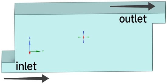
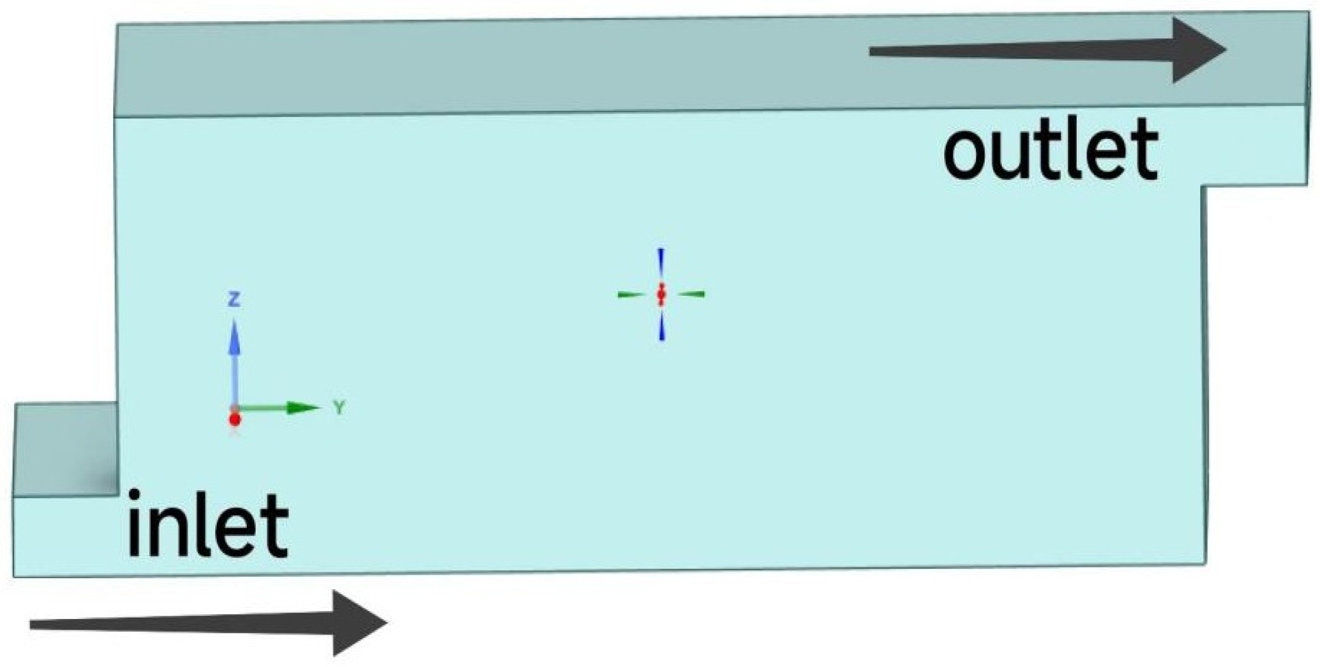
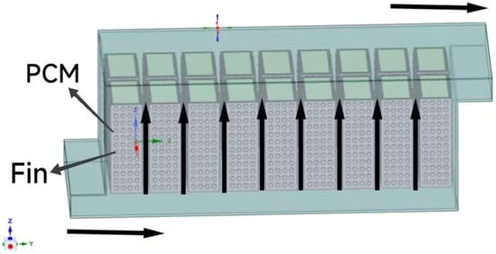
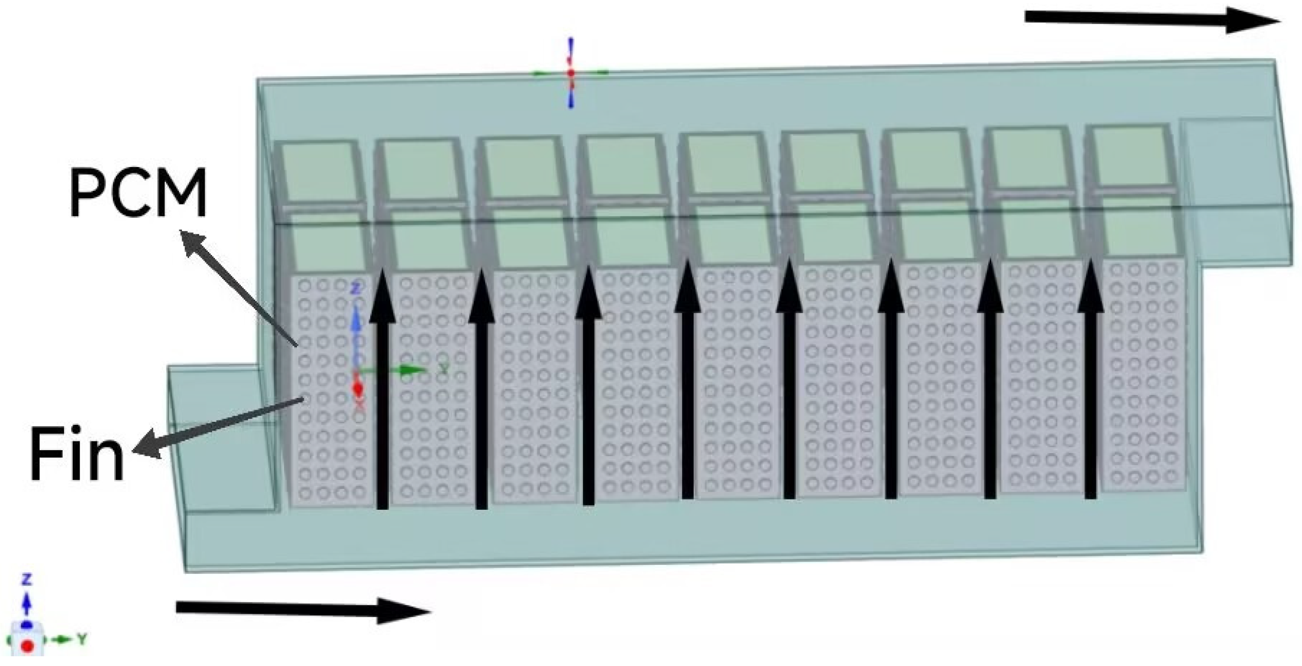
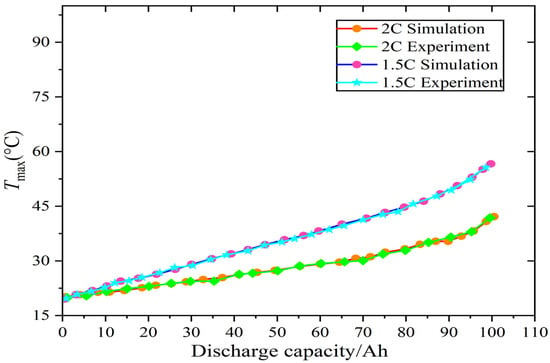
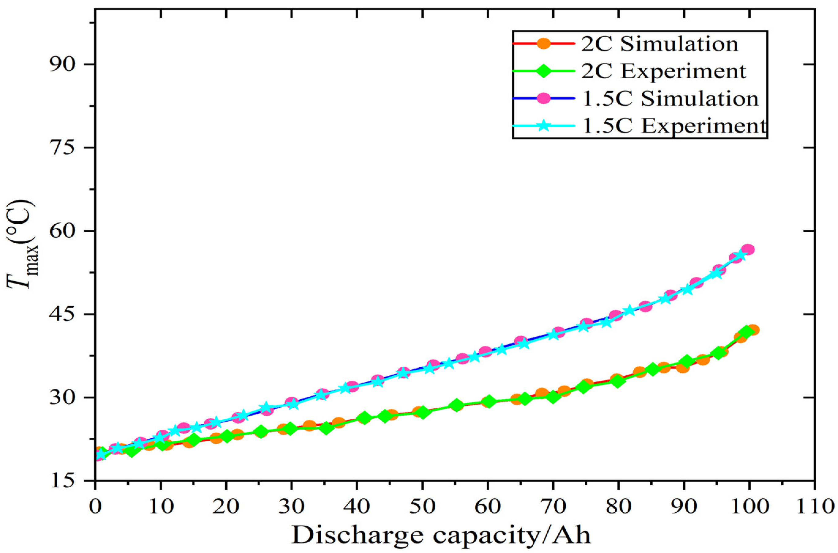
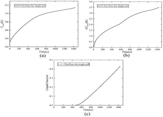
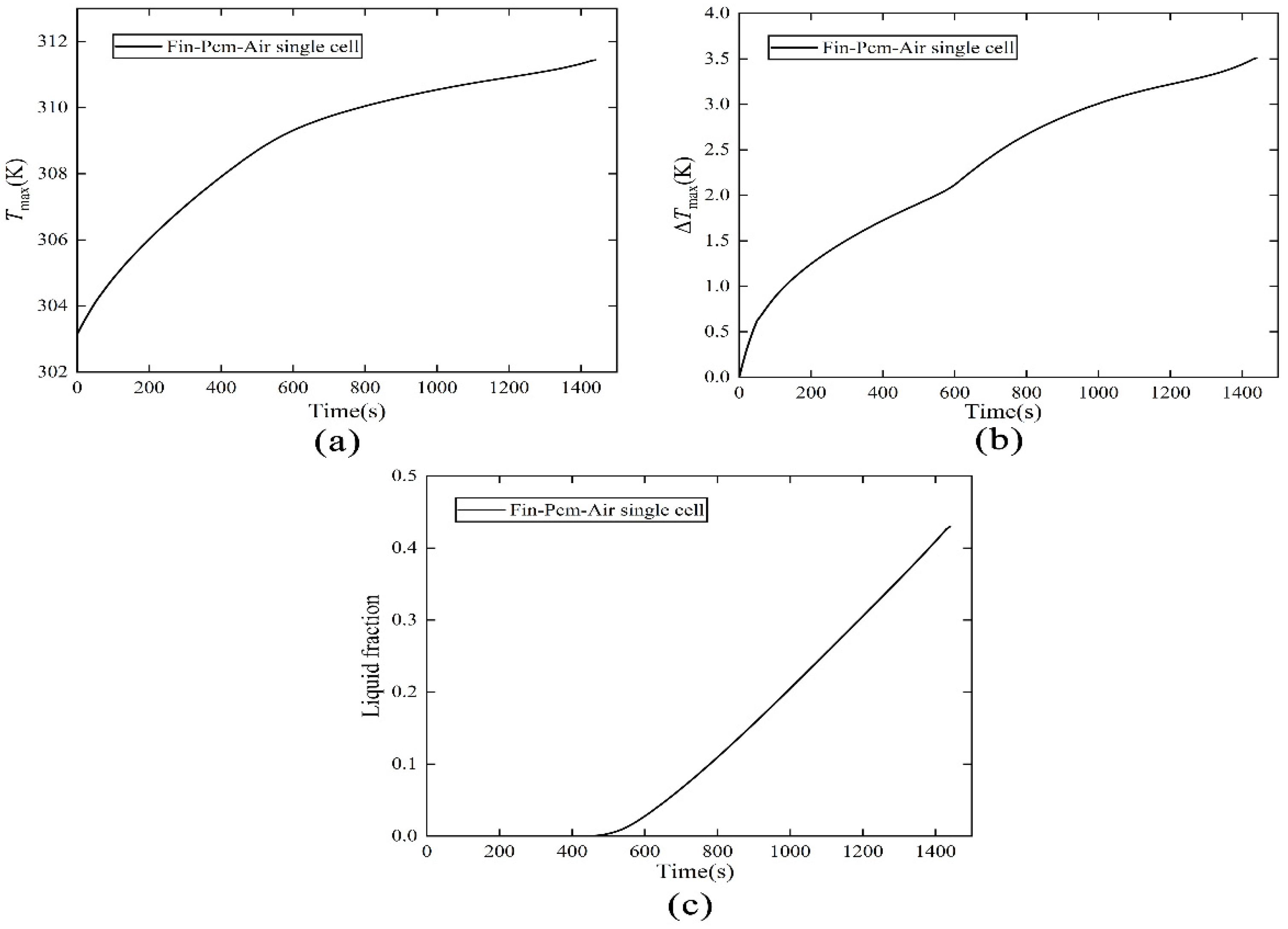
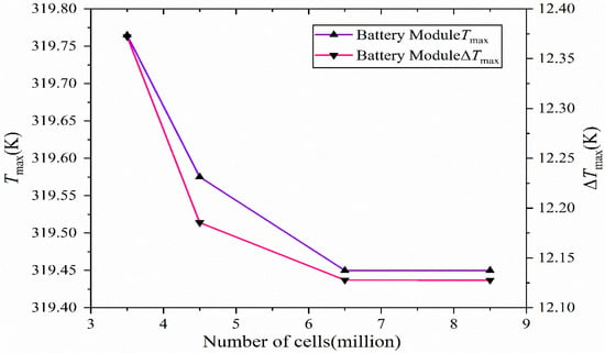
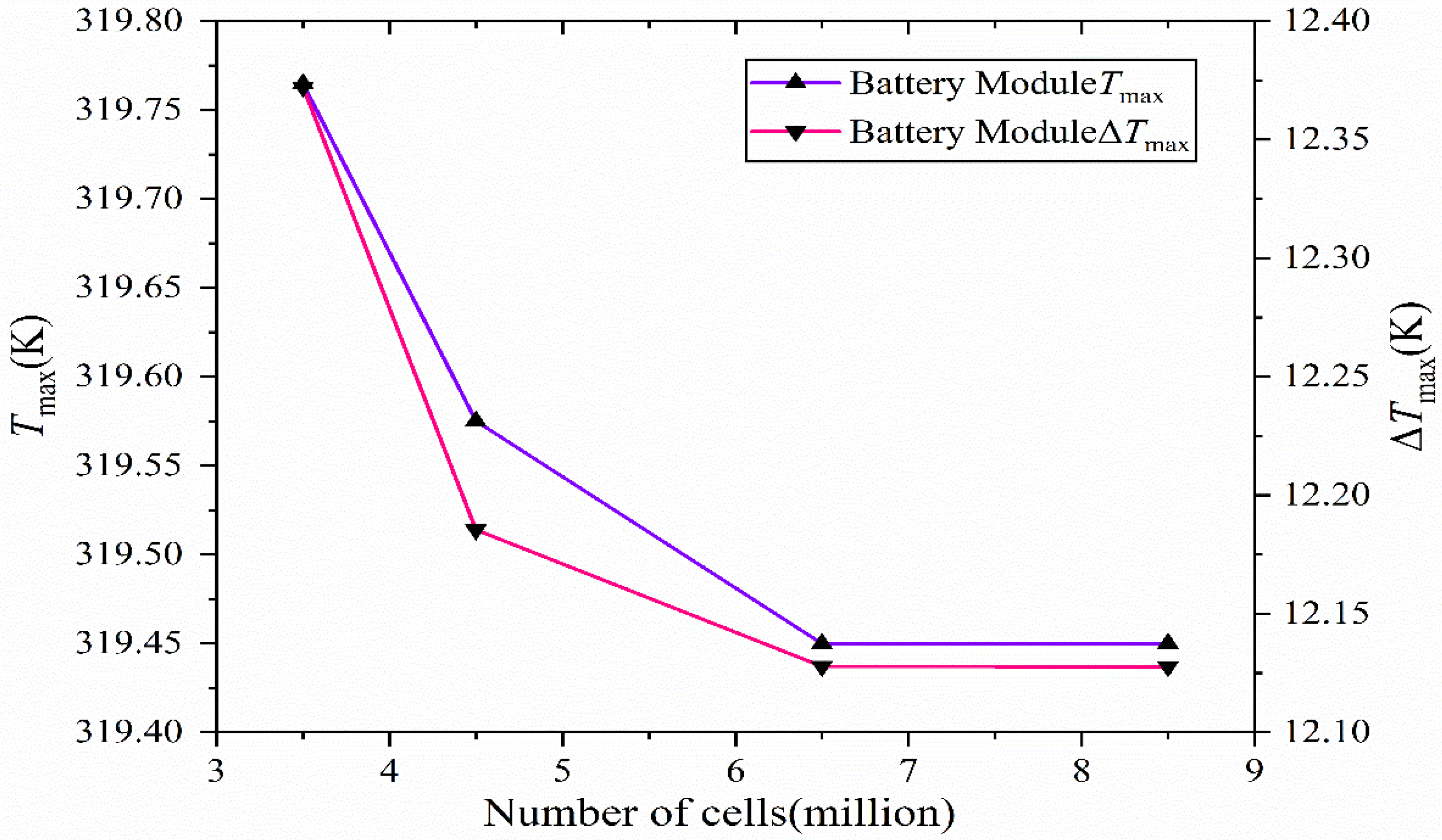
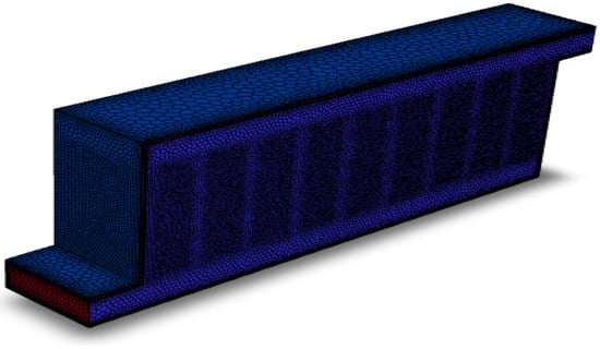
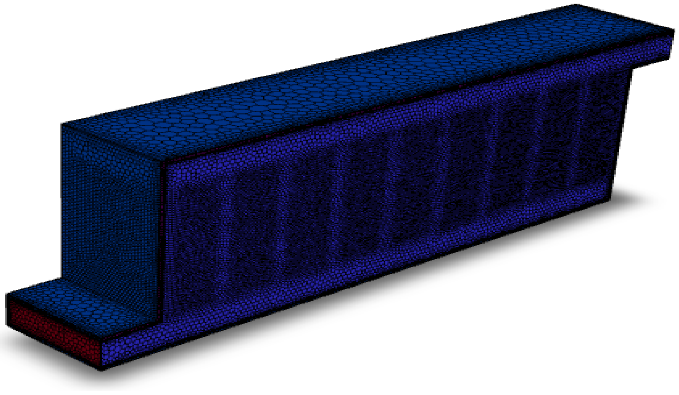
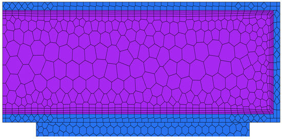
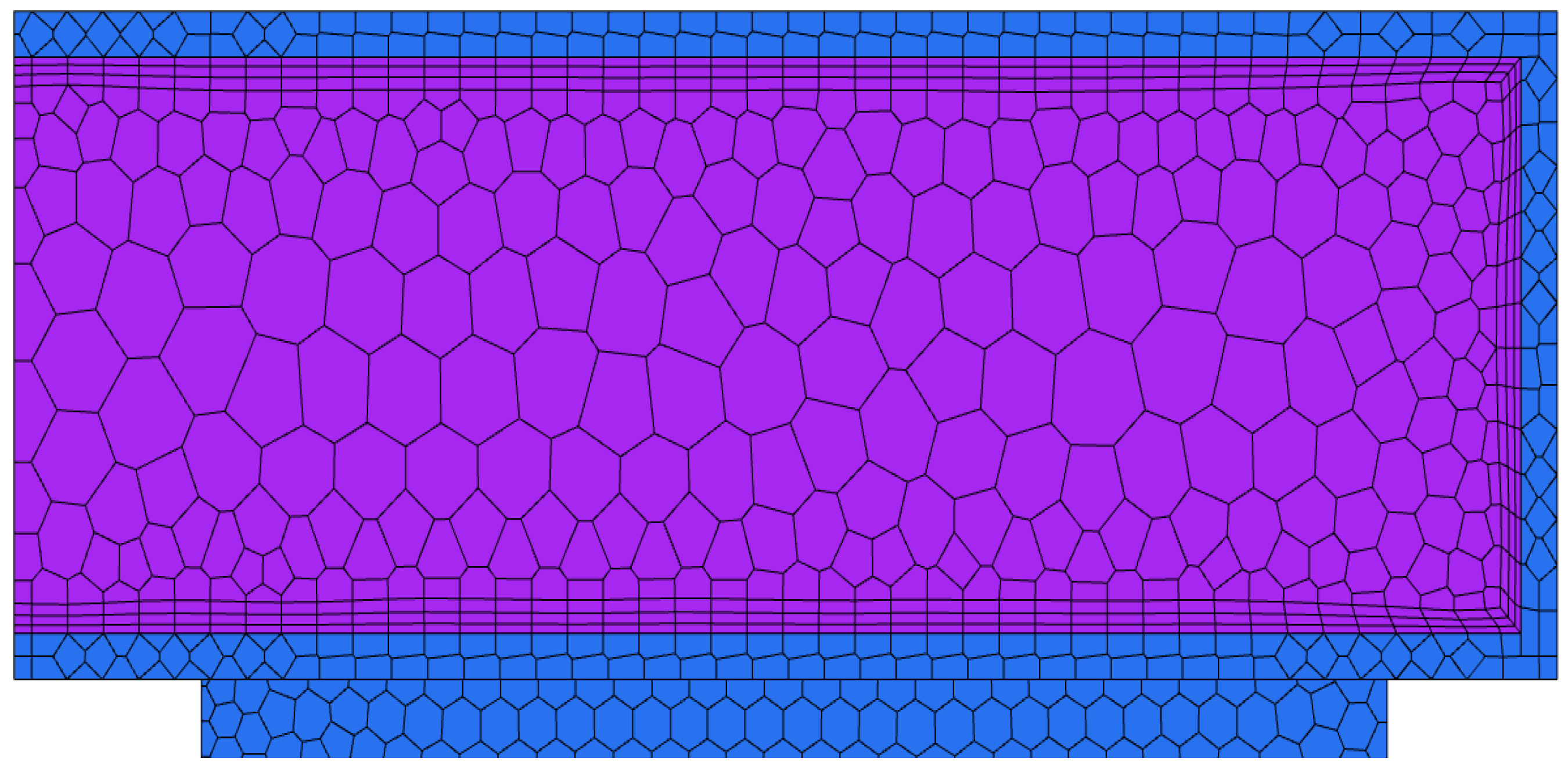
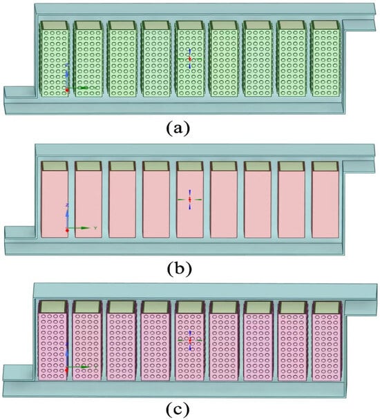
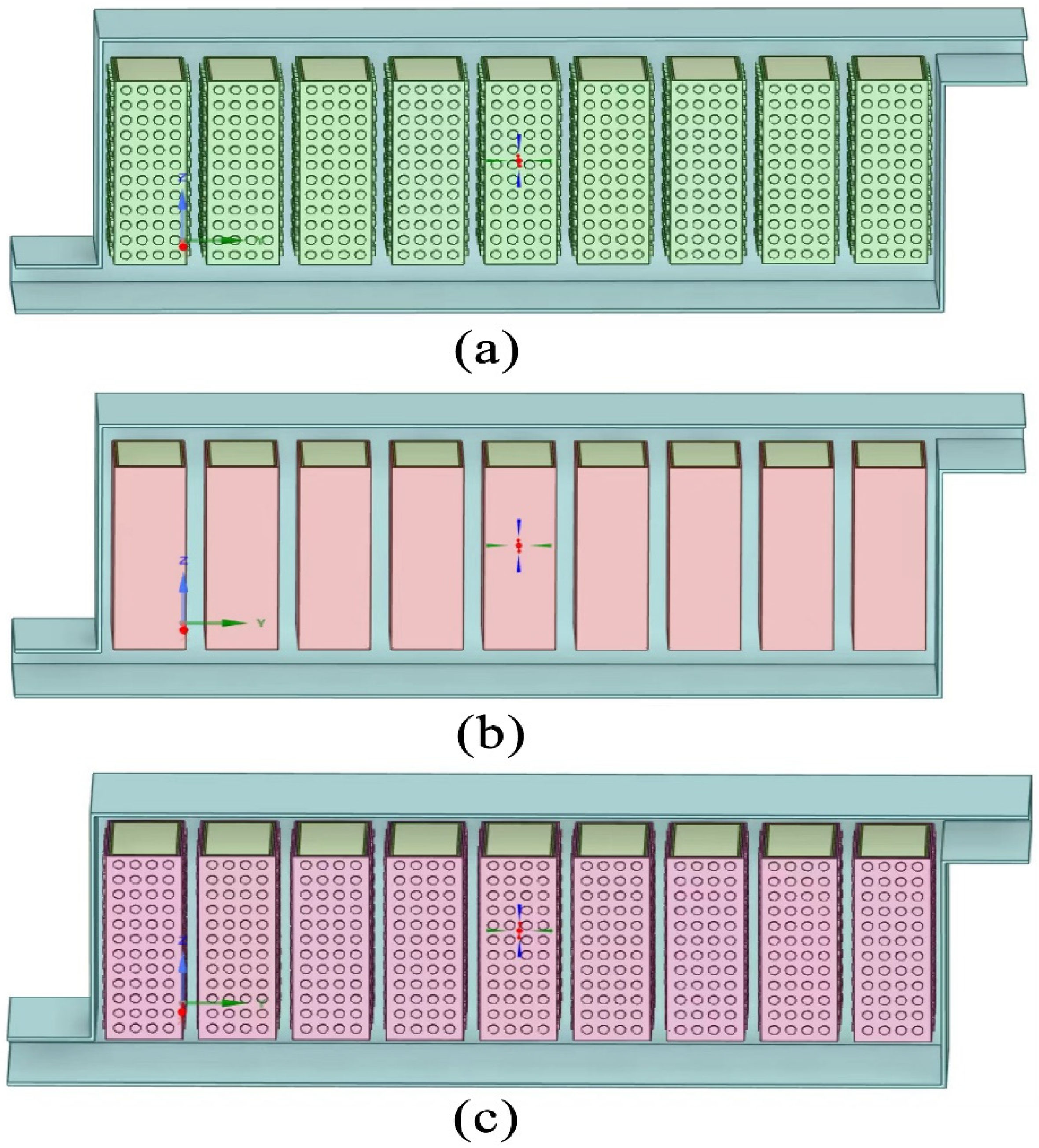
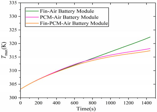
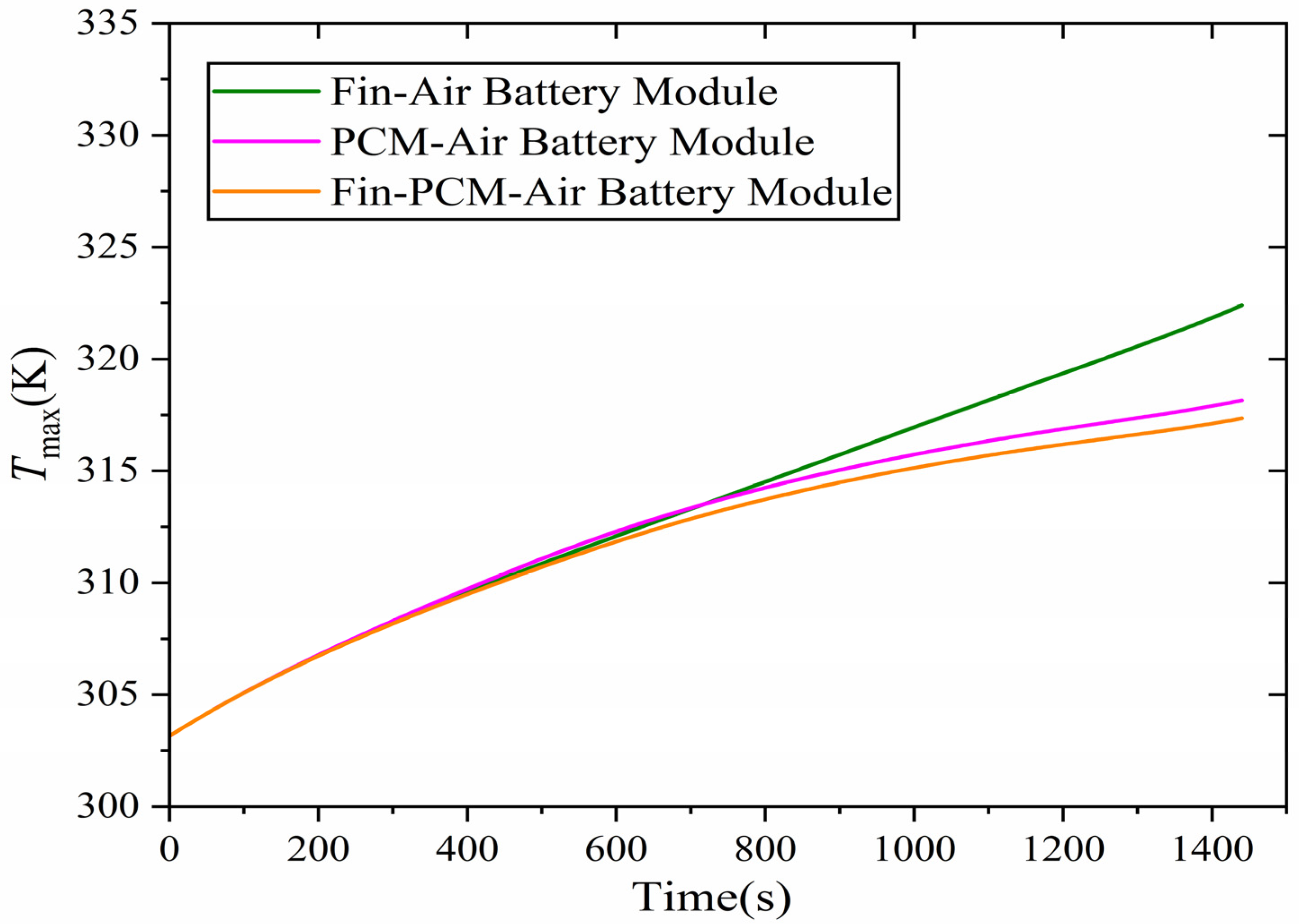
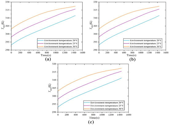
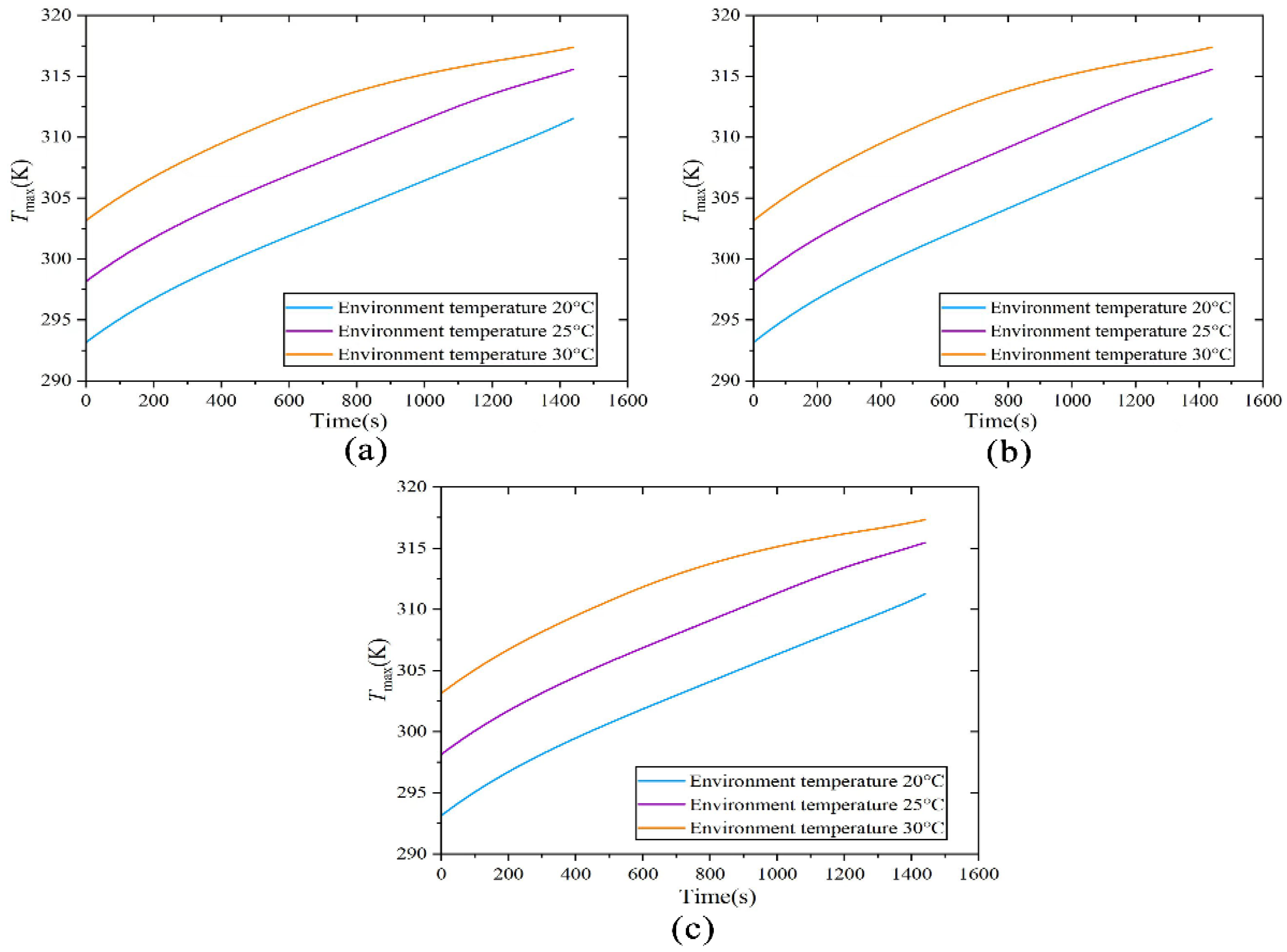
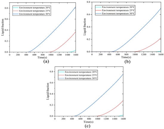
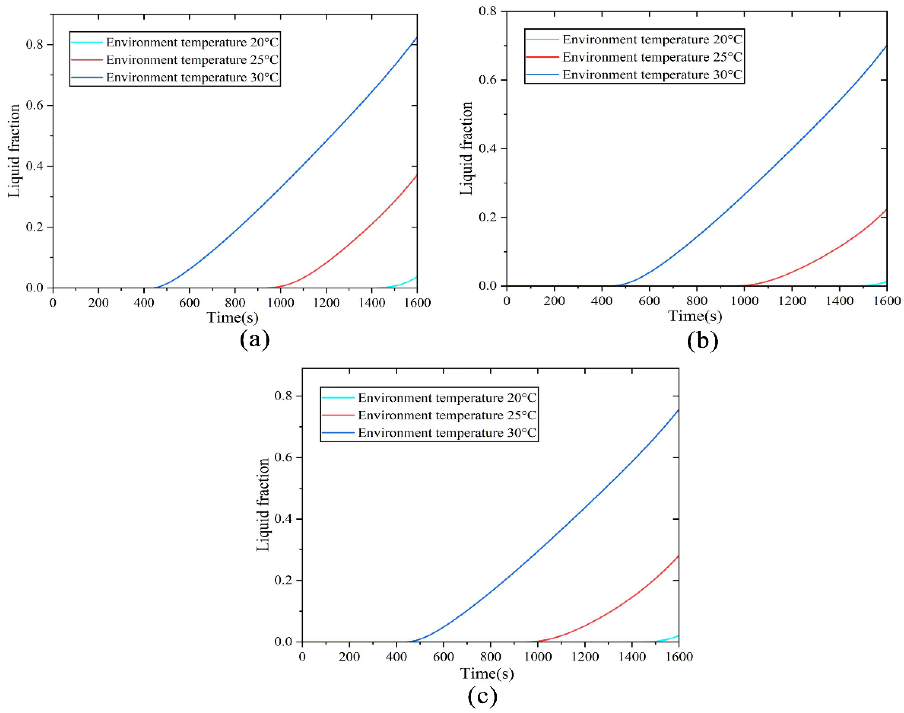
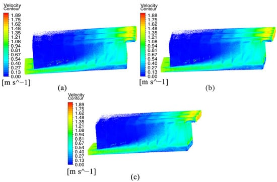
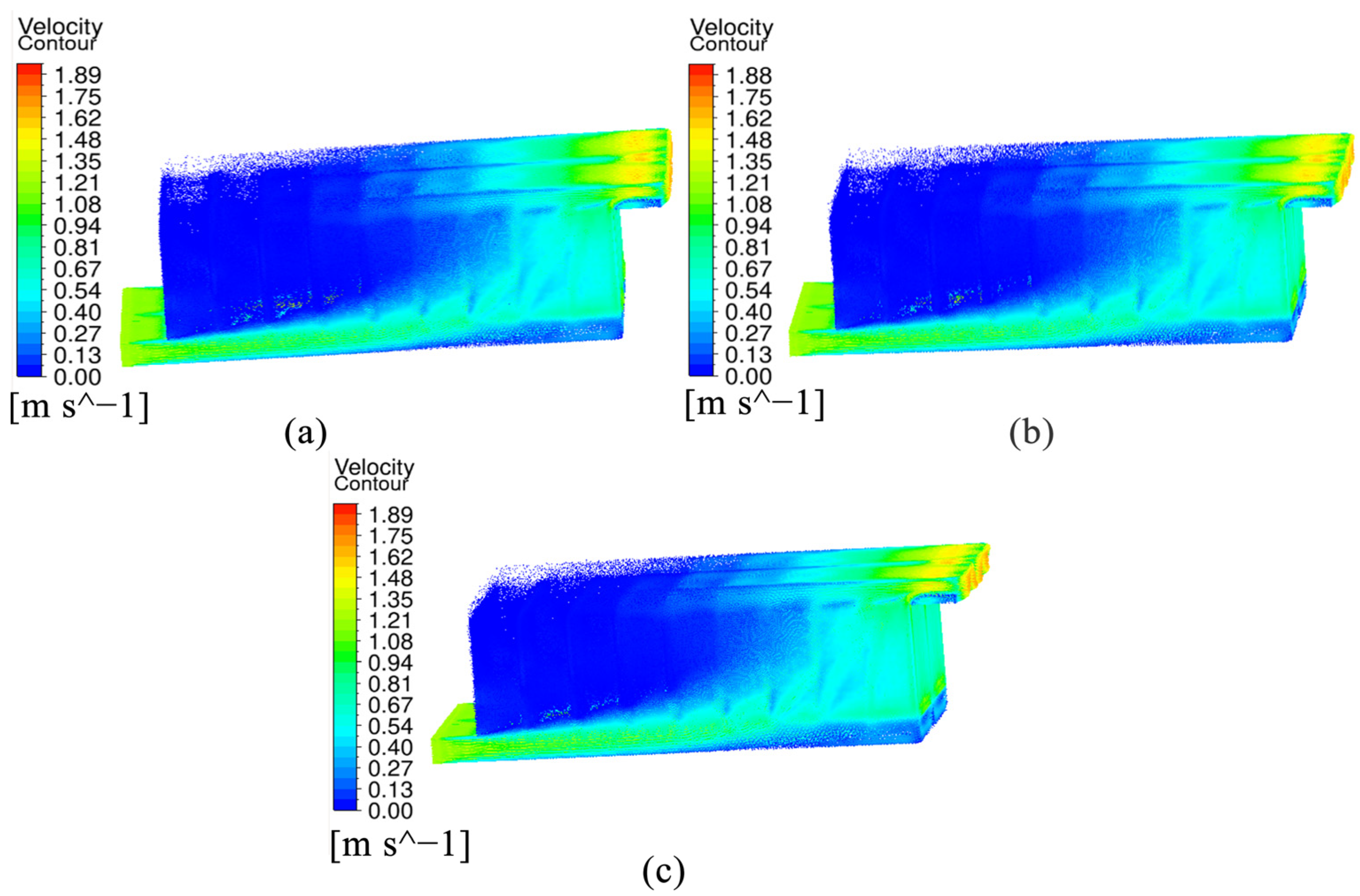
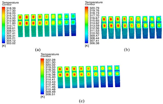
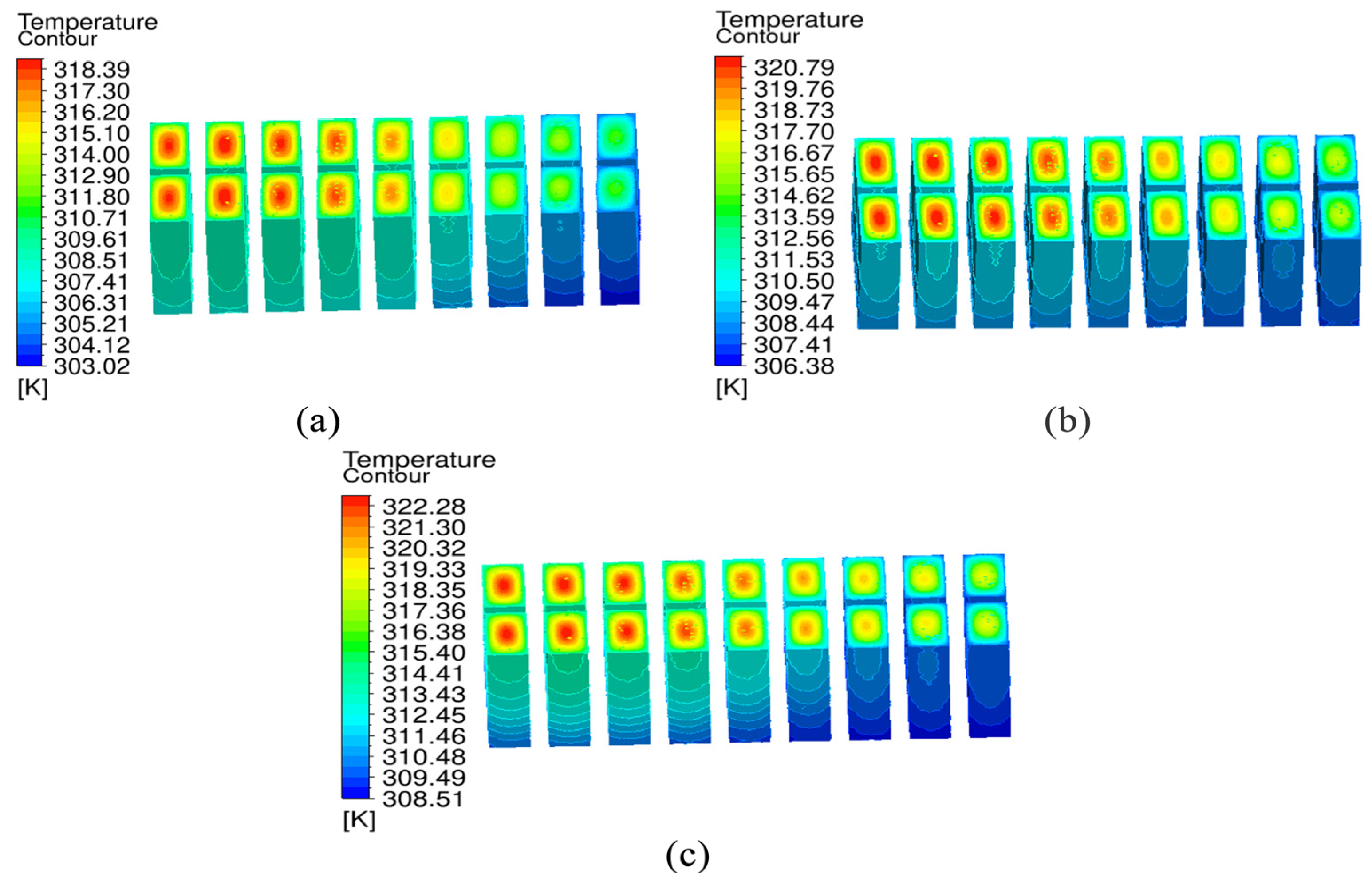
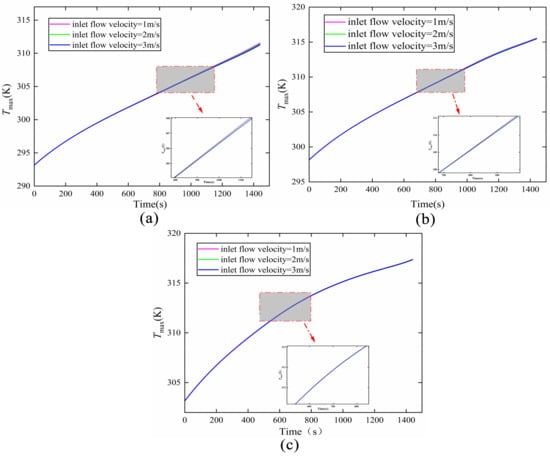
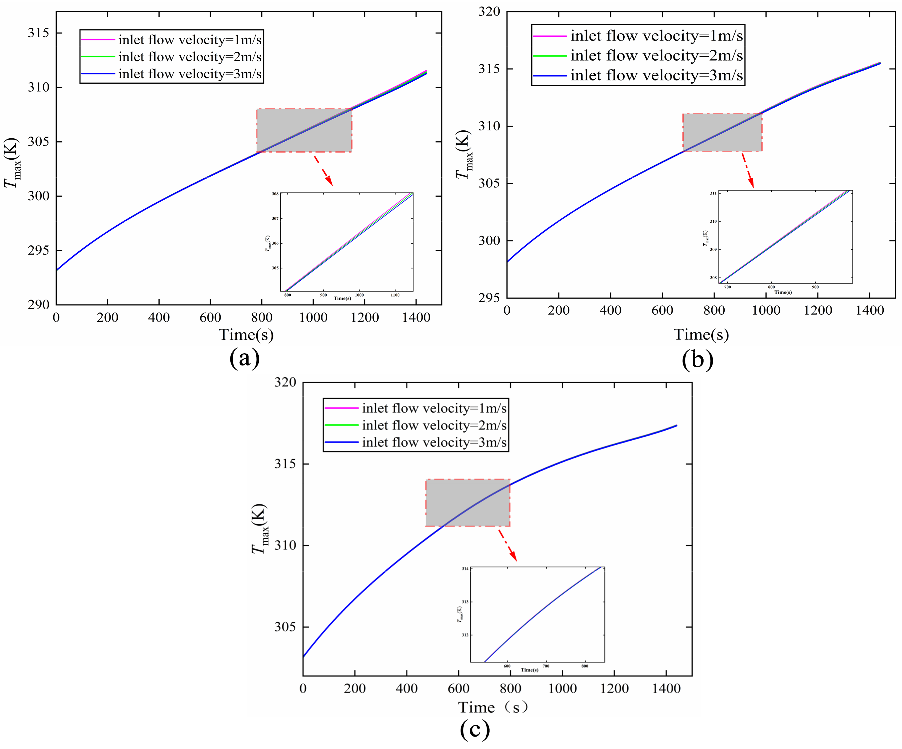
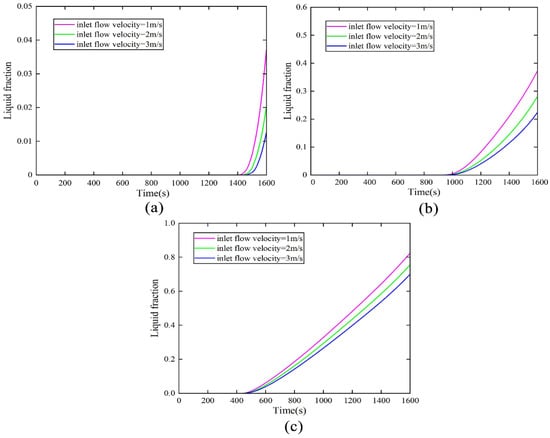
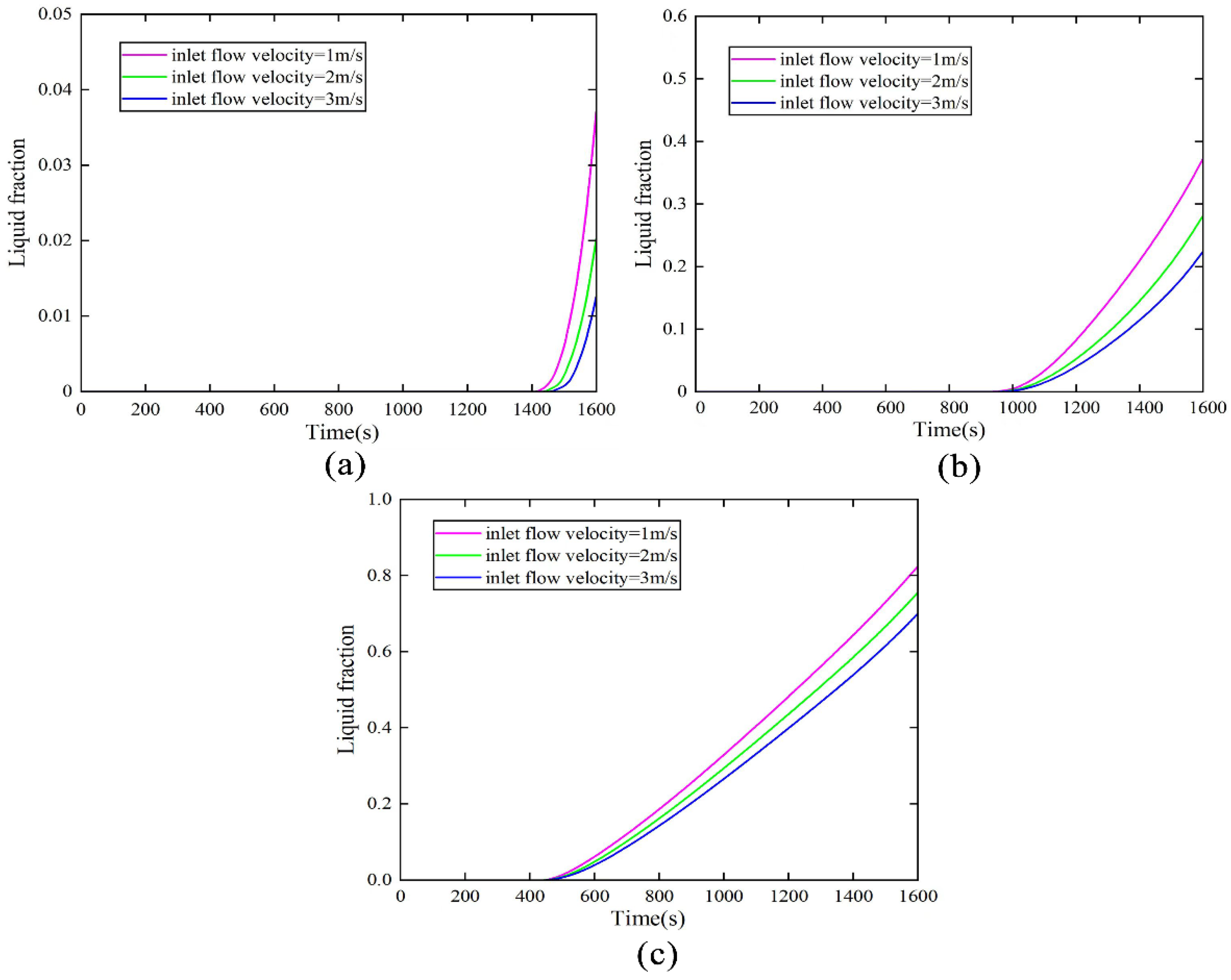
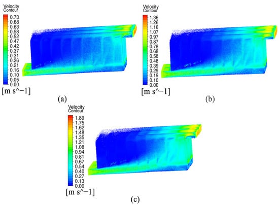
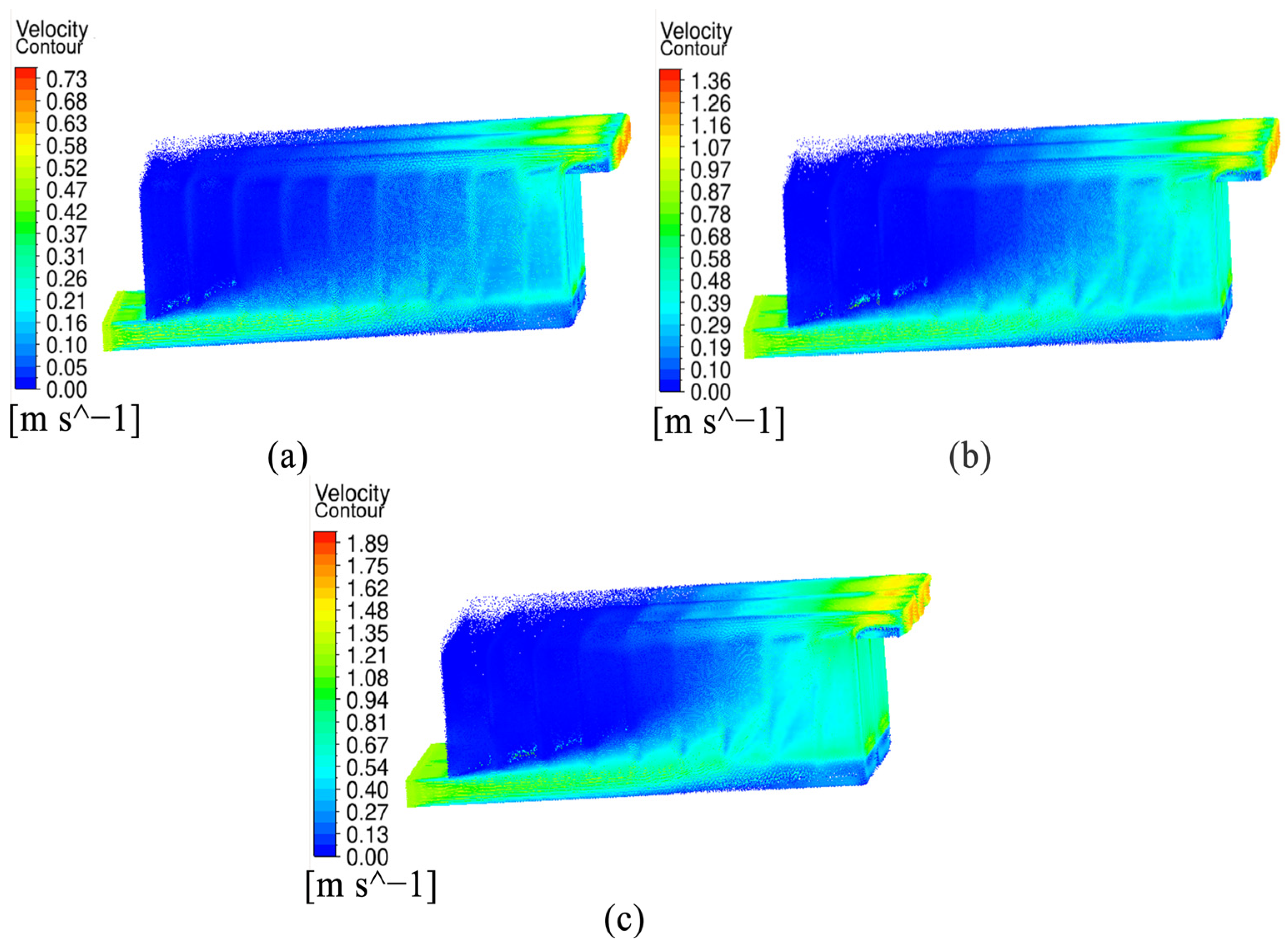
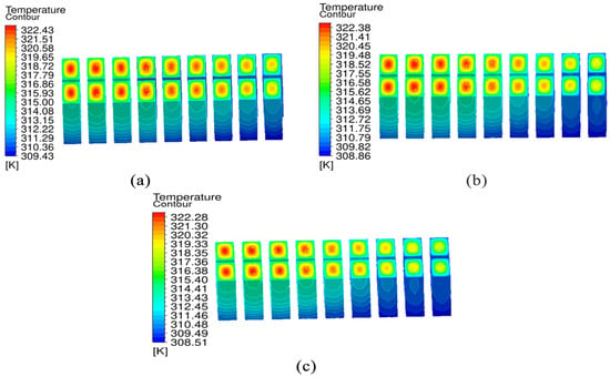
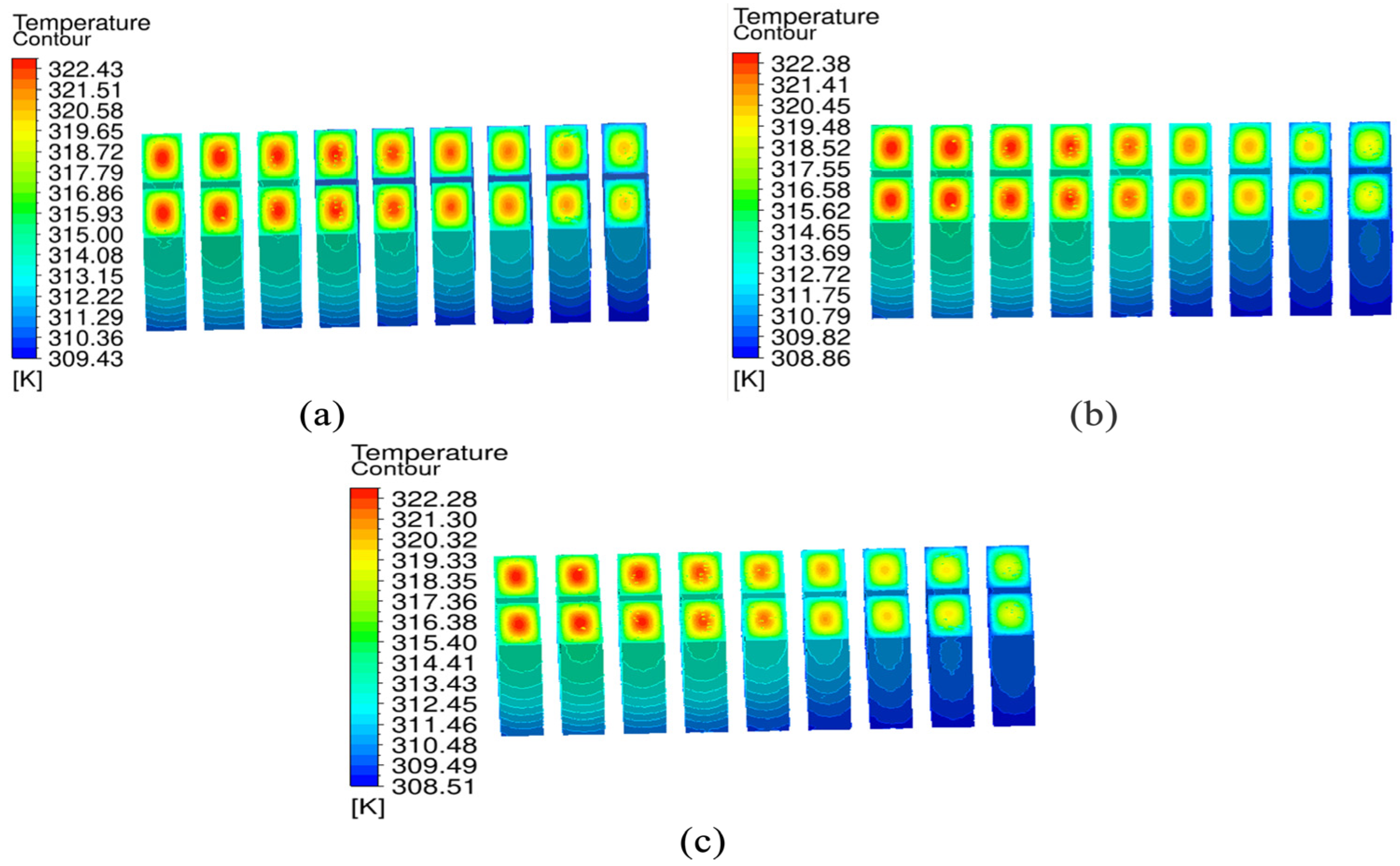
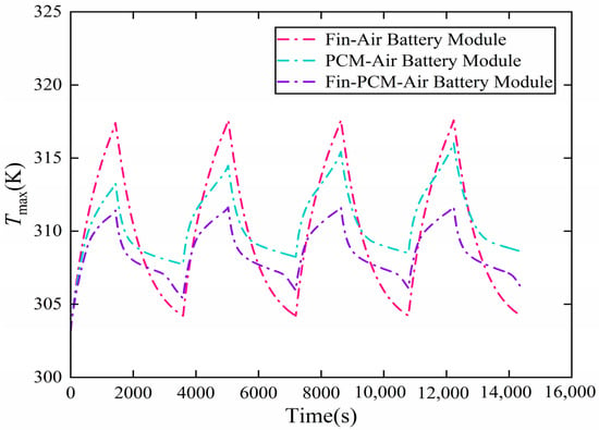
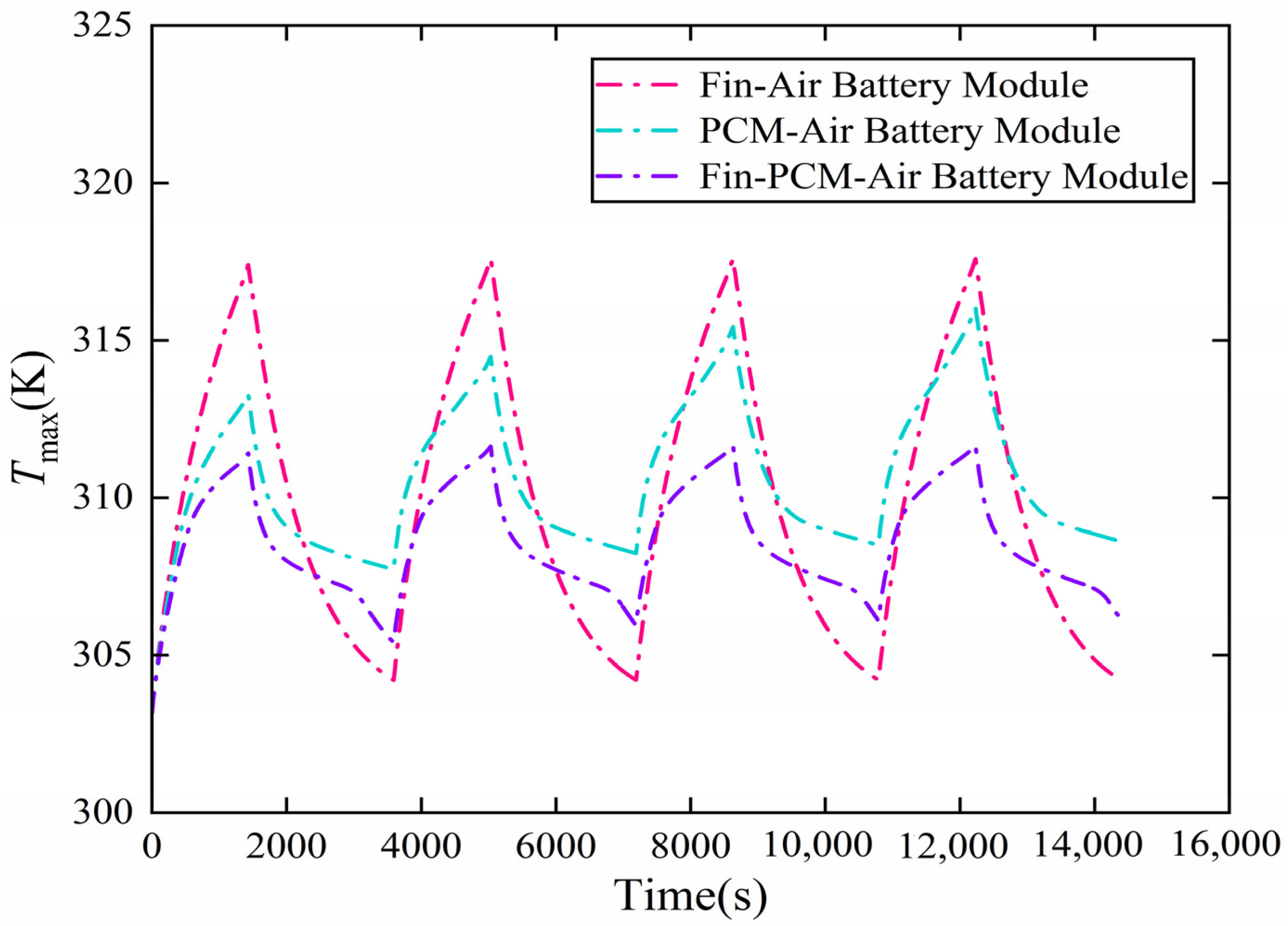
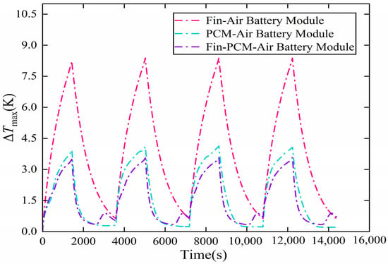
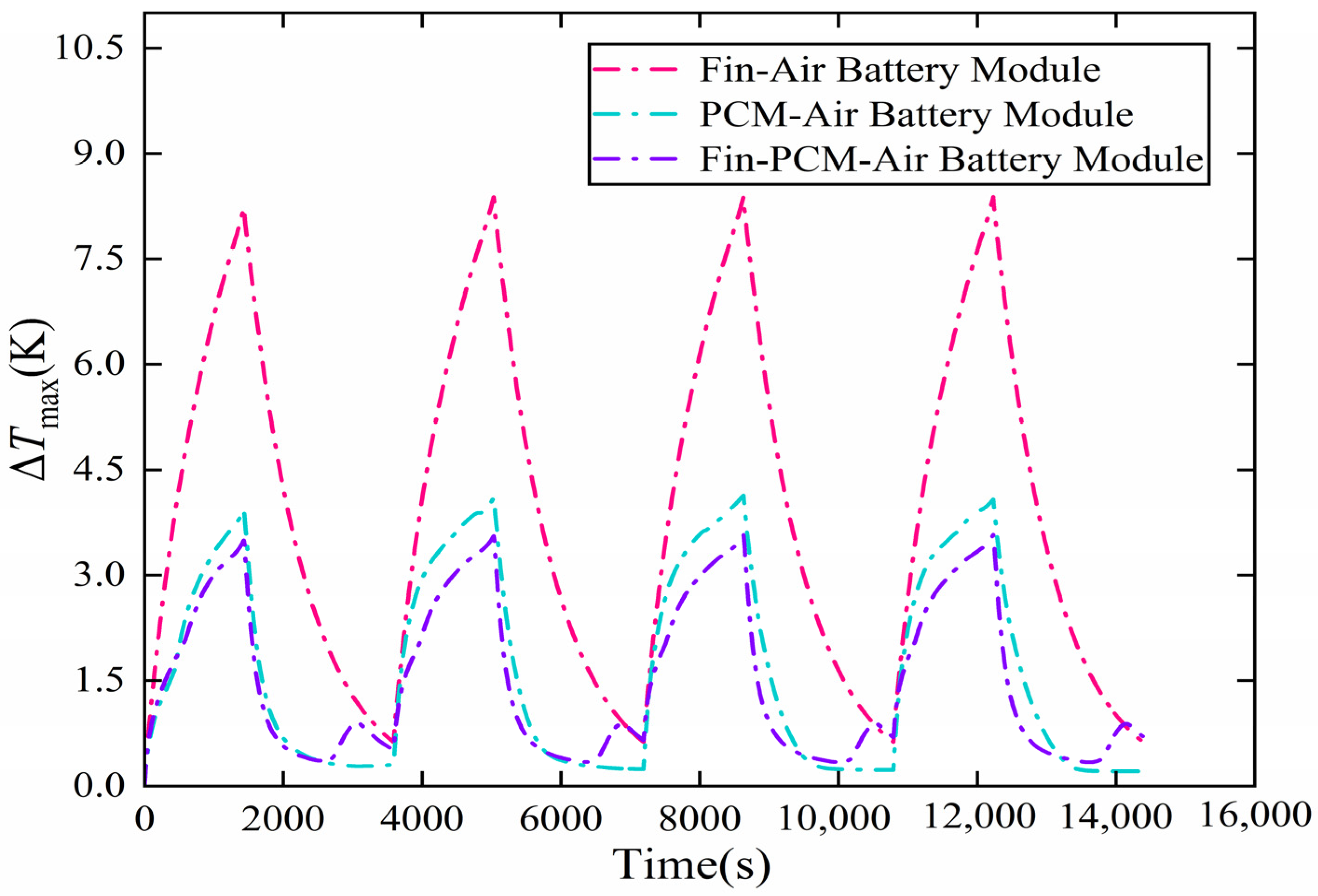
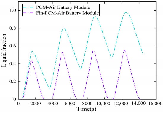
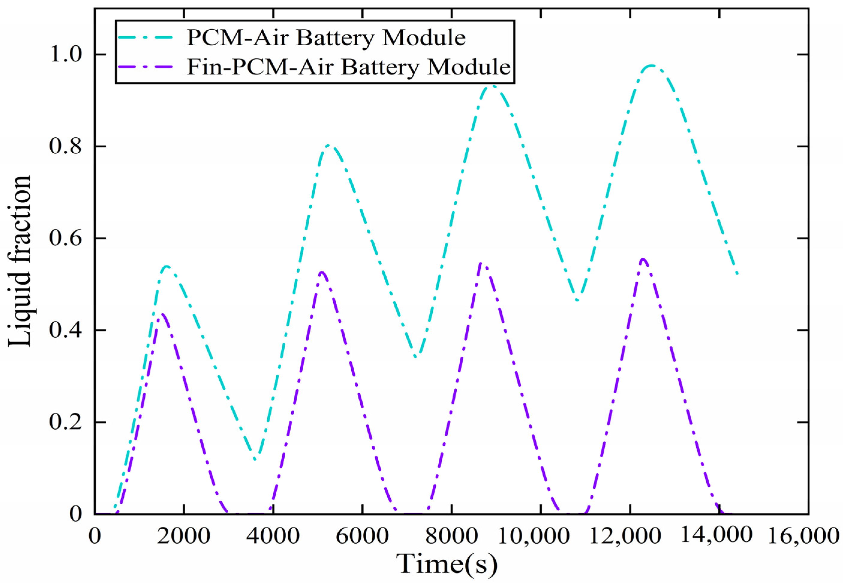

Disclaimer/Publisher’s Note: The statements, opinions and data contained in all publications are solely those of the individual author(s) and contributor(s) and not of MDPI and/or the editor(s). MDPI and/or the editor(s) disclaim responsibility for any injury to people or property resulting from any ideas, methods, instructions or products referred to in the content. |
© 2026 by the authors. Licensee MDPI, Basel, Switzerland. This article is an open access article distributed under the terms and conditions of the Creative Commons Attribution (CC BY) license.