Review

Underground Hydrogen Storage: A Comprehensive Review of Technologies, Geological Formations, and Future Prospects

by
Haval Kukha Hawez
1,*,
Shaee Radha Omar
2 and
Layla Lateef Alwan
3
1
Department of Petroleum Engineering, Faculty of Engineering, Koya University, Koya 44023, Iraq
2
Petroleum Technology-Production and Refining, Koya Technical Institute, Erbil Polytechnic University, Erbil 44001, Iraq
3
Technical Engineering College, Imam Ja’afar Al-Sadiq University, Baghdad 10001, Iraq
*
Author to whom correspondence should be addressed.
Energies 2026, 19(12), 2760; https://doi.org/10.3390/en19122760
Submission received: 25 November 2025 / Revised: 26 December 2025 / Accepted: 1 January 2026 / Published: 9 June 2026
(This article belongs to the Section A5: Hydrogen Energy)

Abstract

Hydrogen (H2) is becoming a meaningful way to store energy for long-term use and support thorough decarbonization in systems that use renewable energy. Underground hydrogen storage (UHS) has strategic benefits over above-ground systems because it can hold large volumes, is contained by geology, and is cheap to operate in cycles. This review compares four key geological formations for underground hydrogen storage (UHS): salt caverns, lined rock caverns, depleted hydrocarbon reservoirs, and saline aquifers. Each system is evaluated based on storage mechanisms, efficiency, safety, technological maturity, and economic feasibility. This review also introduces a unified cross-media evaluation framework, a TRL-risk matrix, a technology development roadmap, and novel insights into AI-based monitoring, offering prescriptive guidance for large-scale UHS implementation. Salt caverns have high injectivity, maintain their purity, and undergo 6 to 12 cycles per year at pressures of 60 to 180 bar; however, they are only found in certain places. Lined rock caverns can be built anywhere, but sealing and economic issues make them difficult to use. Depleted hydrocarbon reservoirs with TWh-scale capacity and already built infrastructure. Saline aquifers, on the other hand, have the most potential in the world but need enhanced management of microbiological responses and cushion gas optimization. A synthesis of current studies highlights key research gaps in cyclic geomechanics, hydrogen–rock–microbe interactions, and liner performance for high-pressure storage. The review concludes with techno-economic and safety considerations and identifies future directions for deploying geological UHS as a critical component of a net-zero hydrogen economy.

1. Introduction

Fossil fuel emissions are a significant contributor to climate change, posing a major threat to the Earth. The quest for sustainable and clean energy solutions has led to a growing interest in hydrogen (H2) as a versatile and environmentally friendly energy carrier. As an essential alternative to existing fossil fuels, H2 can help address urgent environmental concerns, mitigate greenhouse gas emissions, and make the energy landscape more sustainable.
Hydrogen is central to the global energy transition due to its potential to decarbonize sectors such as power, transportation, and industry [1]. Hydrogen has the potential to decarbonize various sectors, including power generation, transportation, chemicals, and heating, due to its clean, versatile, and energy-dense characteristics. Hydrogen does not release carbon dioxide when it is not used, and it can be made from renewable sources [2]. It allows a net-zero carbon economy. Hydrogen must be produced and supplied at a low cost, stored, and integrated into large-scale energy systems to meet the demands of supply and demand [3]. Underground hydrogen storage (UHS) is a key technology in the new H2 economy. It is meant to fix the time difference between when renewable energy is made and when it is needed. As the world moves toward cleaner energy, being able to securely, efficiently, and sustainably store vast amounts of H2 becomes a key part of deep decarbonization.
Underground Hydrogen Storage (UHS) is the best option for large-scale, long-term storage among the current options compared to High-pressure tanks [4], cryogenic storage [5], metal hydrides [6], and adsorption materials [7], which are all examples of surface-based solutions. UHS uses natural and artificial subsurface geological formations to store vast amounts of H2 at high pressure. This is based on decades of experience with underground natural gas storage. Its strategic advantages include a bigger storage capacity (gigawatt to terawatt hours), geological containment for safety, and a lower long-term energy cost per unit [8,9].
This article examines the present and future of UHS by analyzing the primary geological formations utilized for storage, including salt caverns, lined rock caverns, abandoned mines, depleted hydrocarbon reserves, and saline aquifers. Each formation has its own set of challenges and problems that need to be solved. In the US and Europe, salt caverns made via solution mining are already well-known for storing H2 because they are very tight, stable, and can cycle quickly [10]. However, they are limited by their location and have a moderate amount of storage space. Lined rock caverns (LRCs) and abandoned mines are other options when salt formations are not present. They are more flexible in terms of location, but they are also more expensive to build and raise issues about the integrity of the materials used [11]. Depleted oil and gas reserves are very promising because they have been shown to hold geological confinement and have existing infrastructure in place [12]. This makes them good places to store H2 seasonally and strategically. Saline aquifers are the most common and widely spread choice. They have a lot of potential, but they are also the least understood and least explored right now due to geological uncertainty and recovery issues [13,14].
The future use of UHS is closely tied to advancements in H2 generation technology, the expansion of renewable energy, shifts in the energy market, and new regulations. UHS will help balance energy systems, reduce the need to curtail renewables, enable sector coupling, and enhance energy security as countries implement H2 roadmaps and develop H2 infrastructure, including electrolysis hubs, pipeline networks, and storage corridors. However, to make this happen, people from various fields, including geology, reservoir engineering, materials science, microbiology, policy, and economics, need to collaborate.
Although numerous studies have reviewed UHS, most focus on either specific geological systems or isolated aspects such as microbiology, geomechanics, or hydrodynamics. Existing reviews do not provide an integrated comparison across all storage formations using a combined set of criteria for capacity, cyclic performance, geomechanical integrity, microbiological risks, and techno-economics.
Numerous review articles have addressed underground hydrogen storage from specific disciplinary or geological perspectives, such as geomechanics in salt caverns [12], microbial behavior in depleted reservoirs [1], or aquifer hydrodynamics [15,16]. Some studies focus exclusively on a single storage type [17], while others provide broad overviews without applying a uniform framework for comparison [3,8]. In contrast, this review presents a more comprehensive and structured approach. It applies a unified evaluation framework (as shown in Table 6) to systematically compare the four primary UHS types across functional, technical, economic, and environmental criteria. It also introduces an integrated technology readiness and risk matrix that combines Technology Readiness Levels (TRLs) with geotechnical and operational risk assessments. Additionally, the review outlines a phased development roadmap for UHS deployment that aligns with international energy transition targets. Notably, it also provides a forward-looking analysis of how artificial intelligence can be integrated into UHS planning and operations, an area that has been largely overlooked in existing literature.
This study also highlights problems that still need to be addressed, including cyclic stresses, hydrogen reactivity, and cushion-gas optimization. This sets research objectives for the large-scale use of UHS in new hydrogen economies. Table 1 presents a standardized evaluation framework used to compare each UHS method.

2. Underground Hydrogen Storage: Classification and Principles

Underground hydrogen storage (UHS) may mitigate the disparity between supply and demand caused by the variability of renewable energy sources. The UHS method also makes storage safer than standard above-ground solutions since it reduces the amount of oxygen that stored H2 can come into contact with, like in aquifers [1,15].
There has been a lot of recent research on UHS in depleted gas and oil reserves, aquifers, and man-made underground spaces, such as salt and rock caverns. These geological formations have certain good traits, such as (i) being gas-tight enough, (ii) having walls that are much thicker than those of regular storage tanks, and (iii) being very far underground, which makes them safer.
Storing H2 in porous medium, like aquifers or depleted reservoirs, requires the right geological structures, which are different from those needed for storing natural gas. These structures consist of well-confined porous and permeable formations encircled by impermeable cap rock or seals to store H2 with minimal losses safely [16]. Even though the frequency of gas extraction varies, with H2 storage happening more often, most of what we know about storing H2 in subsurface systems comes from storing natural gas (NGS).
Table 2 compares four underground hydrogen storage types by function, characteristics, and problems. Salt caverns provide pure, fast-cycled storage but are costly and location-limited. Depleted fields reuse infrastructure but risk contamination. Aquifers offer large, widespread capacity yet face sealing and microbial issues. Abandoned mines are low-cost but prone to leakage and instability.
Before evaluating each type of UHS, the table below (Table 3) summarizes their current technology readiness, ongoing projects, and level of implementation.

2.1. Salt Caverns

Salt caverns are optimal for extensive, long-term storage to equilibrate fluctuating supply and demand as decarbonization and the implementation of renewable energy accelerate. Salt caverns leverage the near-zero permeability, self-healing characteristics, and chemical inertness of rock salt, in contrast to surface H2 storage tanks or porous formations like aquifers or depleted oil and gas reservoirs [17].
Salt caverns are currently the most mature and commercially deployed UHS method, particularly suited for frequent cycling and high-purity hydrogen storage. Salt caverns have excellent storage and scalability. Over 100,000 to over a million cubic meters can be stored in caves at depths of 500 to 2000 m. Extremely high-pressure H2 storage, usually between 20 and 30 megapascals (MPa), is made possible by these depths and volumes [18]. An example of a project that has demonstrated long-term dependability is the Clemens Dome in the United States, which has achieved an H2 usability rate of 99.8% and over 60,000 pressure cycles without failure [17]. Salt caverns function like large “energy batteries,” storing excess renewable energy during peak times and releasing H2 when demand increases, or output decreases [19,20]. Table 4 presents the key characteristics, advantages, and limitations of using salt caverns for underground hydrogen storage (UHS). It covers aspects such as geological integrity, storage capacity, performance, hydrogen purity, economic factors, and environmental impact. The table highlights why salt caverns are a viable and efficient option for large-scale hydrogen storage, while also outlining their geographic and operational constraints.
Salt cavern storage has also been demonstrated to be cost-effective, particularly in terms of capital expenditure (CAPEX) and the levelized cost of H2 storage (LCOHS). Since solution mining, a well-established and affordable building technology, costs $1–2 per cubic meter, salt caverns are better for the economy [24]. Hydrogen storage in salt caverns is 80–90% cheaper than above-ground tanks. Salt cavern UHS costs $0.39–$2.41 per kg of H2, while surface tanks cost $5.00–$15.00 [17,25]. The geological integrity of salt reduces leakage and monitoring costs, cutting operational costs. The U.S. Clemens project cut development costs by 40% by merging H2 storage with natural gas salt cavern infrastructure [26]. This kind of cost-effectiveness makes it more likely that salt cavern systems can be used on a large scale, especially in areas with salt domes or bedded salt formations.
Salt caves have proven more effective than other types of storage media in changing conditions. For instance, the U.S. Advanced Clean Energy Storage (ACES) project in Utah completed 15 successful injection/extraction cycles with a leakage rate of less than 0.08% per cycle, which is the industry standard [27,28]. The pressure maintenance methods are performed for the German Teesside projects instead of cushion gas [29]. Fiber-optic sensor technologies are also being integrated into wellbores to monitor the structure in real-time and detect leaks early, adding layers of redundancy and diagnostic knowledge [30].
Salt caverns offer superior operational flexibility, with rapid injection and withdrawal capabilities ideal for balancing short-term energy fluctuations [31]. In contrast, the injection and production rates are limited in the aquifers and depleted oil and gas fields because of discrepancies in rock permeability and fluid pressure. Salt caverns serve dual functions for long-term seasonal storage and short-term grid stability [32]. Additionally, because salt caverns maintain H2’s purity during storage, there is no need for complex and expensive purification methods when it is retrieved. This makes operations easier and reduces the cost of downstream processing [27].
Salt cavern storage represents the most technologically mature UHS option, benefiting from decades of operational heritage in natural gas and town gas storage. Proven applications include the pioneering Clemens Dome facility in the USA, which has successfully undergone over 60,000 pressure cycles with 99.8% hydrogen recovery, the large-scale Advanced Clean Energy Storage (ACES) project in Utah targeting 1.5 TWh of green hydrogen storage, and active European pilots such as HyCAVmobil in Germany and the Teesside project in the UK, which integrate storage into regional hydrogen hubs. Economically, salt caverns offer a highly competitive levelized cost of hydrogen storage (LCOHS), driven by capital expenditures for cavern leaching and well completion, operational costs for compression and monitoring, and significant cost-saving potential through retrofitting existing natural gas cavern infrastructure, reducing development costs by up to 40%. Nevertheless, key challenges remain, including geographical limitations to regions with suitable salt deposits, long-term stability concerns related to cavern creep and volume loss, sustainable management of water use and brine disposal, especially in arid areas, and the need to adapt existing natural gas storage regulations to address hydrogen’s higher diffusivity and embrittlement risks.
Solution mining requires a significant amount of water, which poses a sustainability issue in arid regions. The long-term carbon reductions and strategic energy security these systems provide may make them valuable. Improved water management and safe brine disposal may inspire innovative salt cavern designs and operations [33].
Salt caverns are a cleaner choice for storing things than surface tanks or fossil-based storage options from a broader environmental perspective. Salt caverns are a suitable choice for energy infrastructure sensitive to climate change because they leak only small amounts of water, less than 0.05% per year in some U.S. projects. The U.S. Department of Energy’s 2024 Hydrogen Strategy and the European Union’s REPowerEU plan both highlight the importance of underground storage for the growth of the H2 ecosystem [27]. The essay, on the other hand, discusses several technological and regulatory problems.
In salt caves with layers of mudstone or gypsum, permeability goes up by several orders of magnitude, which makes leaks worse. If nothing is done, rocks having a permeability of more than 1 × 10⁻¹⁷ m2 can lose 45% of their H2 over 30 years [34]. Over time, salt rocks slowly change shape, which can cause the cavern to shrink and the structure to become less stable. Some salt caverns lose 1–3.5% of their volume during the course of 30 years [35]. There are rules for storing natural gas, but H2 needs its own risk assessment and material compatibility criteria because it is lighter, more diffusive, and chemically active [36]. Highlighting successful programs like ACES in the U.S. and HyCAVmobil in Germany can help change how people perceive them and promote policy advocacy [37]. Table 5 outlines the distinct technical and operational aspects of using salt caverns for H2 storage. It highlights key features such as their formation, impermeability, storage capacity, and cycle flexibility, along with current global projects and industrial applications. The table also notes specific challenges like hydrogen’s low density and the need for compression, while emphasizing the overall suitability of salt caverns for large-scale underground hydrogen storage.

2.2. Lined Rock Caverns and Abandoned Mines

As part of the global effort to create scalable, safe, and cost-effective storage systems that can balance the intermittency of renewable energy sources and ensure a stable H2 supply for industry and transport, rock caverns and abandoned mines are emerging as viable underground storage sites (UHS) [46]. Both methods are based on the larger idea of subterranean energy storage, which has worked well for natural gas, oil, and compressed air. However, they need to be carefully re-evaluated for H2, which is a small, diffusive, and reactive molecule. Table 6 presents a comparative analysis of Lined Rock Caverns (LRCs) and Abandoned Mines for underground hydrogen storage (UHS). It examines key aspects, such as definition, advantages, challenges, safety, cyclic capability, environmental risks, and technology readiness.
Table 6. Comparative analysis of Lined Rock Caverns and Abandoned Mines for UHS [38,39,46,47].
AspectLined Rock Caverns (LRCs)Abandoned Mines
DefinitionPurpose-built excavations in competent rock, sealed with a multi-layer liner.Pre-existing, often irregular voids from mining activities, requiring significant retrofit.
Primary AdvantageSite selection flexibility independent of specific geology; can be sized as needed.Low initial excavation cost; potential for rapid deployment using existing voids.
Key ChallengesVery high construction cost ($10–20/m3); hydrogen embrittlement of liners; long-term sealing integrity.Poor and unknown geotechnical stability; complex sealing needs; potential groundwater contamination and legacy pollutants.
Safety & IntegrityDependent on liner performance and rock mass quality. Risk of progressive micro-leakage.Inherently high risk due to unknown fractures, connections to the surface, and potential for collapse.
Cyclic CapabilityModerate. Limited by liner material fatigue and thermal-mechanical stresses.Very low. Unsuitable for frequent pressure cycling due to structural instability.
Environmental RiskControlled during construction. Risk linked to liner failure.High. Risks include acid mine drainage, groundwater chemistry alteration, and surface subsidence.
Technology ReadinessPilot stage (e.g., HyBRIT). Proven for compressed air (CAES), not yet for H2.Conceptual/Pre-feasibility stage. Considered high-risk and not recommended for large-scale H2.
On the other hand, abandoned mines are human-made voids left over from prior mining activities. They are often uneven, damaged, and connected to groundwater systems. A thorough analysis of these two storage options, capacity, safety, ease of use, and environmental impact, indicates that engineered rock caverns can be technically viable for H2 storage to some extent. Still, they remain limited by sealing and cost constraints [48,49]. On the other hand, abandoned mines, despite their apparent economic benefits and existing void volume, have ongoing structural, environmental, and operational risks that make them unsuitable for safe, large-scale H2 containment.
When it comes to system capacity, rock caves can store a modest to high amount of H2, depending on geology, excavation design, and pressurization methods. Compressed air or oil storage systems in Scandinavia, for example, can hold between 50,000 and 1,000,000 cubic meters. This means they can store tens to hundreds of gigawatt-hours of energy at pressures between 5 and 15 MPa [50]. The main benefit of rock caverns is that they can be designed in many different ways. However, rock caverns are not very good at storing H2 because they require artificial sealing systems, such as concrete or polymer linings, to prevent gas from leaking through the common microfractures in most crystalline rocks [51,52]. So, even if a rock cavern may have a large theoretical volumetric capacity, its practical H2 capacity, which is the amount that can be safely stored for long periods of time without losing a lot of it, is lower. This limitation is exacerbated in cyclic storage systems, where fluctuations in pressure and temperature cause sealing materials to wear out and microcracks to spread. So, even though rock caverns could theoretically hold a lot of H2, their actual storage efficiency depends not on the size of the cavity, but on how well their sealing methods work and how well they are maintained over time [53,54].
In contrast, abandoned mines have capacity potential that is not always clear and can change [55]. The energy density of stored H2, which is based on both volume and pressure, is still much lower in mines than it is in designed rock caverns or salt formations. Also, the irregular shape of mines makes it hard for pressure to be evenly distributed throughout injection and withdrawal cycles. This creates stress-concentration zones that further reduce usable capacity. Large abandoned mines could be lined with concrete or polymer to make them more stable and better at keeping water out. But these kinds of changes are too expensive and challenging to implement due to the complex access routes and broken infrastructure. Even though abandoned mines may have a lot of space, their actual storage capacity is much smaller. Also, the technical requirements for storing pressurized H2 make it unsuitable for long-term or high-density storage [56].
Safety concerns create a more significant distinction between rock caverns and abandoned mines. In designed rock caverns, safety primarily comes from structural integrity, geostatic confinement, and engineered barriers, rather than from natural impermeability [57]. Hydrogen embrittlement is a well-known problem in steels, cements, and some polymer liners. It is a significant problem because H2 molecules can enter the microstructures of metals or cementitious materials, weakening mechanical connections over time. Studies in laboratories, notably those from German H2 storage research programs, show that keeping material permeability below 10−19 m2 is essential for technical tightness [58]. However, in the real world, rock-cement systems often exceed this level after thermal and mechanical cycling.
Additionally, crystalline rocks do not self-heal like halite formations in salt caverns do. Once a fracture starts, it tends to spread with repeated changes in tension. As a result, the sealing efficiency slowly decreases, and the likelihood of H2 leakage increases over time [59].
Nevertheless, abandoned mines are inherently dangerous places to store H2. The primary safety threats come from geological degradation, unregulated paths to the surface, and leftover pollutants or reactive elements from previous mining operations. Most abandoned mines have groundwater systems running through them. Because H2 can catch fire easily (4–75% in air) and requires very little energy to ignite, even small leaks could pose a serious safety risk. The possibility of H2-oxygen explosions in mine voids with leftover air or oxygenated groundwater should not be ignored, especially in shallow or inadequately ventilated mines [60,61].
The fact that purpose-built rock caverns are easier to utilize and work with makes them even better than repurposed abandoned mines. But the exorbitant cost of excavation and lining, which can range from USD 10 to 20 per cubic meter of storage space, makes them less practical than salt caverns. Also, rock caverns are relatively stable, but they do not have the self-sealing characteristic of salt; therefore, liners and wellheads need to be checked and maintained regularly [62,63]. However, rock caves can be good places to store H2 for the medium to long term if they are built for seasonal or strategic reserves rather than for daily cycling [64].
On the other hand, it is tough to safely or efficiently run abandoned mines [39,65]. Even though reusing existing voids is a good idea since it lowers the cost of initial excavation, the total cost of sealing, monitoring, and risk reduction is often more than building new, purpose-built storage facilities [66]. So, from a practical and economic perspective, abandoned mines are not suitable for use because they are challenging to operate, perform poorly, and incur high long-term maintenance costs [67]. This means they should not be part of a national H2 infrastructure unless they are used under exact, regulated pilot conditions [68]. Table 7 demonstrates the distinct features of rock caverns and abandoned mines for hydrogen storage, focusing on their formation, construction, and operational characteristics. It describes the engineering requirements such as liners, drainage systems, and pressure management, as well as their current applications, including the HyBRIT pilot project in Sweden. Table 7 also highlights the advantages of Lined Rock Cavern (LRC) technology in terms of flexibility, pressure handling, and suitability for dynamic hydrogen storage.

2.3. Depleted Reservoirs

The repurposing of end-of-life oil and gas fields for hydrogen storage, leveraging existing wells, data, and infrastructure for low capital expenditure and a levelized cost of storage around $1.23/kg H2, demonstrates high technical readiness supported by pilot projects in locations like the UK, Austria, and the USA, drawing an analogy to natural gas storage. However, this approach faces specific challenges, including hydrogen interactions with brine and residual hydrocarbons, microbial consumption, gravity override and mixing issues, and concerns over caprock integrity due to hydrogen’s smaller molecule size, all of which are critical considerations outlined alongside storage capacity and infrastructure advantages in its characteristic profile [69].
Hydrocarbon reservoirs containing oil or gas are geological formations that have undergone multiple stages of diagenesis, including source rock development, migration, and the passage of time, to function as storage for hydrocarbons. Typically, these reservoirs are covered by an impermeable layer, often aquifer-supported from the bottom or edges. When a gas field nears the end of its productive phase, it is commonly converted into a gas storage facility. The depletion of a gas reservoir, either already depleted or nearing depletion, is characterized by low pressure and high-water saturation in the region once occupied by gas, owing to aquifer water displacement. Consequently, the gas saturation behind the waterfront varies from minimal, corresponding to residual gas saturation near the initial gas/water contact, to maximal, representing gas saturation near the gas/water contact [70]. A depleted gas reservoir can be conceptualized as an aquifer (geological trap) segment with minimal water in the pores, primarily occupied by trapped gas [71]. Table 8 presents the key characteristics, benefits, and challenges of using depleted reservoirs for underground hydrogen storage (UHS). It highlights their large storage capacity, proven geological integrity, and cost advantages due to existing infrastructure.
Pore volume, permeability, residual fluid saturation, and cushion-working gas interactions determine subsurface H2 storage capacity in depleted reservoirs. Both studies show that depleted gas and oil fields are the best large-scale H2 storage solutions, with GWh to TWh capacities, depleted gas [8]. The study found that cushion gas accounts for 25–80% of reservoir capacity, with CO2 serving as both a pressure-support medium and a long-term sequestered phase.
In depleted oil reservoirs, multiphase H2, brine, and residual oil interactions affect capacity considerably. Hydrogen pore space is reduced by residual oil and water saturations, and hysteresis effects between drainage and imbibition cycles can trap gas in pore throats. Volumetric inefficiencies are mitigated by huge, well-characterized storage capacities and pre-existing infrastructure in many oilfields. After caprock and well integrity testing, many mature oilfields might safely sustain multi-TWh capacities, according to their global reservoir study [75].
Hydrogen’s small molecular size poses containment challenges but facilitates faster pressure equalization during injection and withdrawal.
Underground hydrogen storage safety includes wellbore integrity, caprock sealing, geomechanical stability, and geochemical or microbiological reaction prevention. Both authors agree that depleted reservoirs, which have safely held hydrocarbons over geological timeframes, allow secure confinement if H2’s peculiar features are handled [64].
The primary safety problem in gas reservoirs is gas mixing and gravity override, where buoyant H2 migrates upward over denser cushion gases, expanding the interfacial area and incurring purity losses. Williams et al. observed that horizontally widespread formations with thin vertical thickness increase mixing. The study also found that natural heterogeneity, like poor vertical permeability layers, reduces gravity override. To avoid up-coning and cross-flow, homogenous formations need operational rate control [76].
Safety is less important than the integrity of the caprock. Both studies stress the importance of keeping an eye on capillary entrance pressure and fracture thresholds to keep H2 from leaking through micro-fractures or clay interlayers because its molecular radius is only 0.12 nm. Dilshan et al. [77] used the Young–Laplace equation for capillary sealing to quantify the stable height of an H2 column beneath the caprock based on wettability and interfacial tension. Pore throat residual trapping makes it harder to recover, but it also provides a safety buffer. The evaluation found that depleted oil reservoir safety assurance requires hydrodynamic modeling, geochemical analysis, and microbiological risk assessment.
Ease of use refers to the H2 storage system installation, operation, and cycling. Both studies underline that exhausted hydrocarbon resources include wells, pipelines, and geological data from previous production periods, making them highly operationally convenient. Building new salt caverns or aquifers is much more expensive than using this infrastructure.
As the cushion-gas ratio increased, withdrawal efficiency improved, and pressure–volume relationships were predictable and stable. They also showed that injection-well design and rate schedules can balance dispersion and gravity segregation to improve H2 extraction rates.
Understanding fluid–fluid and fluid–rock interactions simplify oil reservoir operations. The scientists noted that H2 storage’s cyclic nature stresses the caprock; therefore, real-time seismic and pressure studies are needed to verify mechanical stability during charge–discharge operations.
Hydrogen manufacturing plants are near oilfields, making deployment easier. Integrating H2 storage into energy infrastructure might simplify logistics and save transportation costs for many refineries and petrochemical plants near mature oilfields. Bibliographic analysis also showed that most research and pilot programs are in regions with well-mapped depleted reservoirs (USA, China, UK, Saudi Arabia, Germany, and Australia), indicating an increasing global preparedness to repurpose hydrocarbon assets for clean-energy storage.
The environmental impact of underground H2 storage includes lifetime emissions, land use, subsurface ecosystem disturbance, and carbon sequestration. Both studies recommend drained reservoirs because they reuse geological formations instead of building new surface infrastructure, reducing ecological footprints.
Williams et al.’s innovative use of CO2 as a cushion gas combines H2 energy storage with carbon capture and storage (CCS) [78]. One geological site can be used as a dual-use decarbonization system, temporarily storing H2 for renewable intermittency and permanently storing CO2 in the reservoir’s bottom strata (depleted gas). The simulations show that this configuration improves H2 storage efficiency and reduces greenhouse gas emissions by immobilizing large amounts of CO2. If structural and caprock seals are intact, the CO2 leakage risk is small as it remains immobile below the H2 zone.
Chemical and microbiological processes complicate the environmental safety of oil-bearing formations. Redox changes caused by H2 injection can dissolve or precipitate minerals, releasing trace metals or changing groundwater chemistry. Most reactions are gradual, and site selection (favoring reservoirs with inert lithologies such as quartzose sandstones) reduces long-term dangers. Hydrogen conversion to methane or H2 sulfide by microbes may cause local pollution. Reduce these processes by sterilizing, controlling injection temperatures, or excluding CO2 when not necessary.
From a systems perspective, both studies see UHS as crucial to large-scale renewable integration. Excess wind or solar electricity can be stored as H2 and released during demand peaks to reduce the energy system’s carbon footprint. Ali et al. [79] add that reusing exhausted fields reduces surface disturbance, avoids drilling footprints, and uses existing monitoring wells for environmental surveillance. Standardized subsurface H2 regulations are needed to ensure environmental compliance and minimize unforeseen interactions with neighboring aquifers.

2.4. Aquifers

Hydrogen is an integral part of decarbonized energy networks since it can be used in many ways and has a high energy density per mass. For large-scale H2 energy storage, we need safe, cheap, and eco-friendly ways to store it. Salt caverns, exhausted hydrocarbon deposits, and saline aquifers are suitable for the environment and cost-effective, especially when there are not many alternative formations around. Saline aquifers are huge, have a lot of pore volume, and have been studied for decades for use in natural gas storage and carbon capture and storage (CCS) projects. They can provide geological, hydrodynamic, and operational information for H2 storage.
Aquifers are made of porous, permeable sedimentary rocks soaked with saline water and covered by impermeable layers. Hydrogen injection displaces brine and fills pore spaces as free gas. Storage behavior depends on H2–brine displacement, capillary trapping, dissolution, and buoyant migration. Hydrogen has lower density, viscosity, and brine solubility than natural gas, which affects its subsurface flow and recovery efficiency. In aquifer models, H2 recovery factors reach 78%, with a potential global energy efficiency of 40% (electricity-to-H2-to-electricity).
Big aquifers can store enough for the nation. For example, Canada’s Keg River Aquifer can store 3.24 Mt H2 (~2.3 EJ), meeting its national grid’s seasonal energy needs. Aquifers are the most accessible and environmentally friendly choice for large-scale H2 storage since they are widespread and generally near renewable power sites [80].
Salt caves are far smaller than saline aquifers, which may store several times more. For grid-scale and seasonal applications, their pore volume, geological stability, and area allow multi-terawatt-hour energy storage. Formation depth, porosity, permeability, and caprock integrity affect storage. Sedimentary basins worldwide, including North America, Europe, and Asia, include thick aquifers appropriate for this use [81].
Recoverable H2 makes about 20–50% of the injected gas, while the rest maintains reservoir pressure as cushion gas. Aquifers may need 80% more cushion gas than depleted reservoirs, requiring a significant but reasonable capital expenditure. Injection pressures, caprock thresholds, and migration paths must be determined by numerical modeling and site characterization. Table 9 shows the key characteristics, advantages, and limitations of using saline aquifers for underground hydrogen storage (UHS). It emphasizes their vast global potential and minimal surface impact but highlights major challenges such as low hydrogen recovery, high cushion gas requirements, and uncertain geological sealing.
With vast global potential and proximity to renewable hubs, saline aquifers offer scalable, long-duration hydrogen storage, despite challenges in recovery and site uncertainty.
Safety is key to aquifer storage. The best aquifers are tectonically stable, far away from fault zones and folded strata, and have enough sealing pressure to keep gas during injection and withdrawal. Evidence from past natural gas and CO2 storage operations shows that well-designed aquifer systems are safe.
Integrated system design, geological screening, material engineering, operational management, and robust monitoring supported by transparent regulations and stakeholder engagement determine safety performance.
After site characterization, saline aquifers are easier to deploy than other large-scale storage solutions. Aquifers use pore spaces, unlike salt caves, which need costly excavation. They can be built alongside renewable energy and H2 hubs using existing gas infrastructure.
Compressed H2 is injected into the aquifer using wells, generating a storage plume like natural gas. A portion is permanently trapped as cushion gas; the rest is seasonal working gas. Reservoir management, optimizing pressure gradients, minimizing viscous fingering and gas channeling, and regulating contamination, determines system performance.
However, aquifer operations require complex modeling, control, and site-specific tweaking. Complex modeling and pilot testing are needed to account for fluid-rock interactions, multiphase flow dynamics, and heterogeneity. These procedures are feasible under regulated settings, according to laboratory research and field analogs like town-gas storage in Germany and France.
Integration potential makes aquifer storage easy to integrate with electrolysis plants, renewable energy sites, and H2 transport networks for seamless conversion and dispatch. The small surface footprint reduces environmental impact.
The greenest subterranean H2 storage method is a saline aquifer. It does not displace freshwater or dispose of brine like some salt caverns. Aquifers are deep below potable water zones, so maintaining sealing integrity reduces groundwater contamination risk.
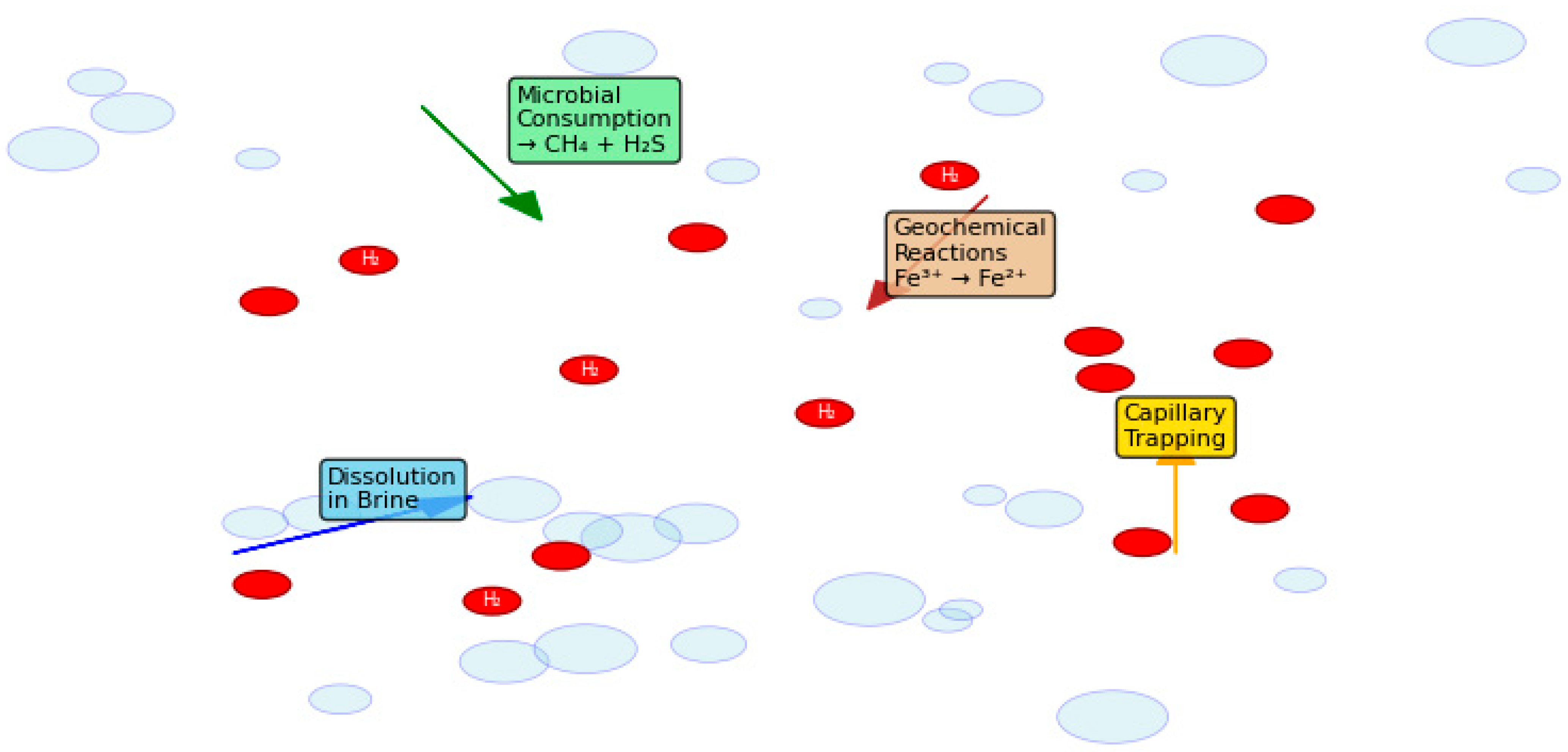
Since H2 is non-toxic, modest leaks offer little ecological risk, but its flammability requires containment. Indirect impacts from injection pressures may include subsurface microbial changes, mineral changes, or modest seismic reactions, recognized from CO2 storage analogs, as shown in Figure 1. Comprehensive risk evaluations and environmental monitoring are required for public acceptance, say the authors.
Large-scale H2 storage helps decarbonize the electricity system, promoting environmental sustainability. Aquifer storage buffers intermittent renewables, lowering fossil-fuel peaker plants and ensuring clean power. Lifecycle analyses show that H2 storage in aquifers has a much lower environmental impact than batteries or compressed air.
Public perception is a key social and environmental aspect. Transparency regarding safety, environmental preservation, and community benefits builds trust. Participatory governance—involving local stakeholders in site selection and oversight—can reduce resistance and speed project rollout.
Economically, aquifer storage is competitive. The average levelized cost of H2 is $1.29 US/kg, second only to depleted oil and gas reservoirs ($1.23 US/kg) and far lower than salt or hard-rock caverns ($1.61–2.77 US/kg). Aquifers. Modest operational expenditures for compression energy, maintenance, and monitoring follow capital-intensive site search and construction. As H2 prices fall, cushion gas expenses, the key capital lock-in, diminish.
Government, industry, and academia should collaborate to improve research, pilot projects, regulatory standards, and social acceptance, according to the study. Scaling aquifer storage internationally and integrating it into H2 supply networks requires continuous monitoring, adaptive management, and legal clarity.
Geological abundance, environmental responsibility, and technical scalability combine in saline aquifer H2 storage. Its system capacity outperforms existing storage technologies, allowing national and continental seasonal energy balancing. Aquifers are essential to the net-zero transition due to their high pore volumes, widespread availability, and proximity to renewable sources.
Mature engineering and regulatory procedures make safety challenging but manageable. To reduce the risk of CO2 and natural gas storage, you can use site-specific geological characterization, sealing integrity-based caprock selection, corrosion-resistant materials, and extensive monitoring networks based on decades of expertise. Design, operational optimization, and surveillance can keep an eye on chemical reactions, H2 embrittlement, and leaks, as well as microbial consumption. The safety of H2 depends on the surface and geological systems.
Using current skills and infrastructure simplifies utilization. Mature drilling, compression, and pipeline technology need only minor H2 adaptation. Flexible operational cycles allow seasonal and short-term storage and fast grid stabilization response times. Regional H2 hubs with renewable electricity and industrial customers are possible with modular aquifer storage.
Sustainability and low environmental impact are supported by aquifer storage. The deep geological framework keeps H2 separate from biospheric processes and lowers environmental stress by stopping brine discharge and surface disturbance. More usage of renewable energy sources indirectly lowers greenhouse gas emissions, air pollution, and the use of resources. Keeping an eye on the environment makes sure that it stays safe for a long time and for the ecology.
Saline aquifers are the backbone of the global H2 economy because they combine capacity, safety, utility, and care for the environment. Even if there are rules, high cushion gas costs, and gaps in subsurface microbiology, research and pilot projects are filling them. Aquifer H2 storage offers a technologically and ecologically sound means to store energy securely, large-scale, and sustainably as nations decarbonize.
The study concluded that saline aquifers are the most fantastic geological medium for long-term H2 storage since they can hold a lot of H2, are safe for the environment, are easy to work with, and are cheap. If they are studied, regulated, and used by the community, their use could speed up the world’s move to a carbon-neutral energy system.
The storage concept is based on the use of deep, porous, saline-saturated rock formations as the subsurface medium for hydrogen storage, where gas is injected and withdrawn through wells in a manner analogous to other underground storage technologies. These formations are characterized by a vast global storage potential; however, they require a large volume of cushion gas to maintain pressure and deliverability, and they are associated with significant geological uncertainty due to heterogeneity in rock properties. In terms of technological maturity, this option has the lowest technology readiness level, with development largely confined to numerical simulations and laboratory-scale experiments, such as those conducted under the H2020 “HyUsPRe” project, while knowledge from CO2 and natural gas storage provides useful analogies. Economically, saline aquifer storage benefits from relatively low infrastructure capital expenditure, but the high cost of cushion gas results in substantial capital being locked up, leading to a levelized cost of hydrogen storage of approximately USD 1.29 per kilogram of hydrogen, which is highly site-specific. Key challenges include maximizing the hydrogen recovery factor, managing the complex fluid dynamics of a highly mobile gas, reliably predicting geochemical and microbial interactions within the reservoir, and ensuring robust site characterization and selection.
Accurate assessment of injection potential and assurance of the safety and efficiency of H2 storage depend on evaluating the technological challenges connected to large-scale H2 storage in saline aquifers. Essential factors in aquifer storage include the footprint of injected H2 underground and its retrieval during cyclic injection/recovery processes. Several elements determine effective storage operations: geological formation characteristics, capacity, fluid and hydrogeological qualities, geological interferences, operational conditions, regulatory frameworks, and societal support.
Table 10 illustrates numerous reviews accessible to the public regarding UHS, spanning various perspectives such as geological analysis [82,83], microbial behavior [1,8], and detailed examinations of hydrodynamics [8], geomechanics [84,85], geochemical interactions [42], and well integrity [8]. Despite the comprehensive coverage provided by these reviews, a focused analysis of depleted gas reservoirs and lined rock caverns remains absent.


3. Challenges and Opportunities

H2 emerges as a strong contender for replacing traditional fossil fuels as the dominant energy carrier in the foreseeable future. Among the several ways energy can be stored nowadays, subterranean geological formations are the most practical. This paper repeatedly recommends four basic underground geological storage media types, deficient reservoirs, saline aquifers, and salt caverns, in great detail. Many agree that UHS guarantees a sustainable energy future for the rising world population. The increasing number of scientific papers on UHS supports the good agreement among scientists. Still, the change from Underground Gas Storage (UGS) to UHS offers many difficulties that must be resolved. Geological, technical, financial, and political elements affect whether UHS is adopted worldwide. Emphasizing operating sites and technical challenges, including hydrodynamics, geomechanics, geochemistry, and microbiology, this analysis provides a platform for guiding research activities in UHS. By defining the general extent of this review, it aims to simplify the following projects in the field of research. Table 11 compares the operational envelopes and key performance indicators of various underground hydrogen storage (UHS) technologies, including salt caverns, lined rock caverns, depleted reservoirs, and saline aquifers. It covers factors such as depth, operating pressure, gas recovery rates, cushion gas requirements, loss mechanisms, material challenges, and technology readiness levels (TRL).
Due to their identified reservoir properties and characteristics, depleted reservoirs and saline aquifers exhibit larger storage capacities than salt caverns. Consequently, salt caverns are deemed unsuitable for UHS in regions with denser populations that necessitate significantly higher energy production [1].
Among the four geological formations under consideration, depleted reservoirs emerge as the most dependable option for UHS, owing to their track record of successfully accommodating natural gas for both seasonal and long-term storage purposes [11]. However, when cyclical storage is prioritized, especially in areas with low populations, salt caves show more viability. Their lowered need for cushion gas and improved capacity for repeated injection and withdrawal cycles help to explain this [3].
Conducting a thorough risk assessment for a particular UHS operation requires careful evaluation of the frequency and degree of every possible risk factor. A holistic review should encompass aspects such as temperature and pressure fluctuations, the risk of leakage, contamination, and flammability throughout the operational phases [1]. Additionally, among the various methodologies proposed in the literature for risk assessment, the reliability criteria maintenance approach emerged as the most effective for storing H2v in salt caverns [94].
When considering potential locations for UHS, assessing them using data analogous to natural gas storage is essential. The overall criteria for site selection should encompass geological, economic, and technical factors [95]. Safety considerations in site selection for UHS primarily revolve around reservoir lithology, the exploration stage for salt caverns, and the exploration stage and volume for depleted reservoirs and aquifers [13].
Sandstone formations should be given priority when storing H2 in depleted reservoirs and aquifers since their better permeability improves H2 storage efficiency. Furthermore, in cases of extended injection times, formations with strong water-wet properties are better [96]. It is also important to avoid storing H2 at depths greater than or equal to 3700 m, as below this threshold, natural upward migration of H2 through the caprock may occur. Strictly dipping structures with stratified barriers can mitigate issues like viscous fingering [13].
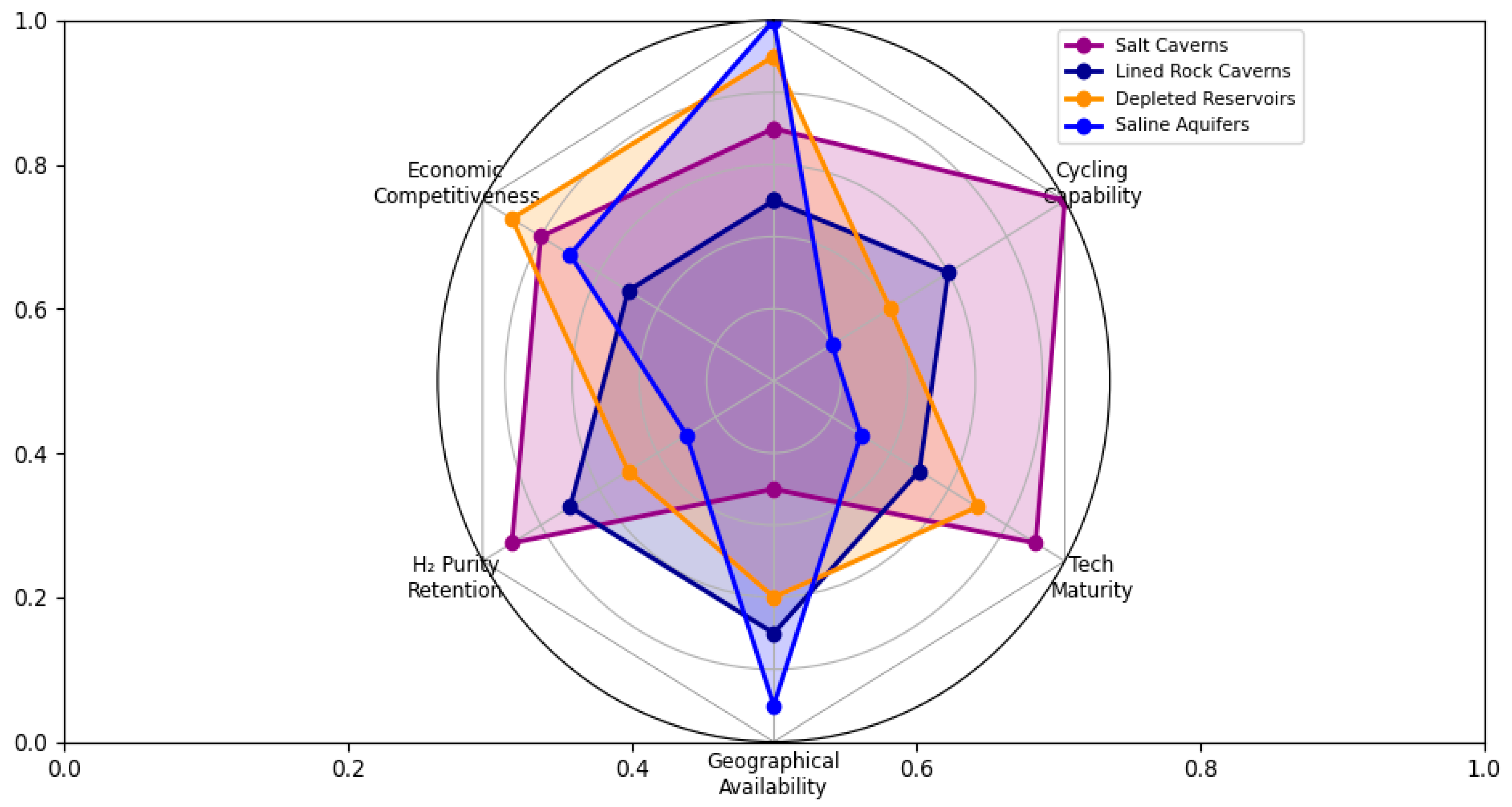
Efficient storage of H2 heavily relies on strategic placement and management of injection and withdrawal wells. Multiple shallow wells below the caprock for extraction and injection are advised while optimizing rates to prevent issues like viscous fingering and lateral gas migration [86]. This approach not only enhances H2 recovery but also minimizes contamination and consumption by microbial and geochemical processes underground. Implementing successive injection-withdrawal cycles further boosts H2 recovery rates. Figure 2 illustrates the comparison of economic competitions, H2 purity retention, cycling capability, technology maturity, and geographical availability for all UHS types.
When constructing salt caverns for H2 storage, it is preferable to target salt domes rather than bedded salt formations. The latter tend to contain interlayers that facilitate H2 migration during operational cycles. Maintaining brine temperature throughout construction is essential to avoid changes in cavern structure resulting from thermal stresses [97]. Furthermore, setting project goals ahead of time is critical since the cavern shape directly affects deliverability.
During operation, continual pressure and temperature monitoring is imperative to prevent thermal or tensile stresses that could deform the lined rock cavern or lead to fractures over time. Maintaining internal cavern pressure within 24–80% of the rock’s overburden pressure provides a safety buffer. Operating at higher temperatures or lower pressures is discouraged to mitigate risks [98].
Injection of H2 can trigger geochemical reactions in the reservoir, altering its mineralogical and petrophysical properties over successive cycles. To mitigate capacity reduction, storing H2 in quartz-rich sandstone reservoirs is recommended from a geochemical perspective [99,100]. Furthermore, microbial activity caused by increasing subsurface H2 concentration in UHS operations can provide economic issues. It is advisable to spot low CO2 concentration depleted pools. Additionally, surrounding reservoir rocks should have high concentrations of reactive iron-bearing minerals and low concentrations of SO4−2 and CO3−2 bearing minerals to minimize unwanted microbial activity [96].
On the other hand, a creative solution meant to cut storage costs and improve the volumetric efficiency of H2 uses solid carriers inside reasonably priced storage tanks. Utilizing metal hydrides or specialized nanostructures, H2 gas molecules can be stored in tanks with lower pressure requirements. However, such storage devices need low temperatures for H2 absorption and heat for gas molecule release. Therefore, cost-effectiveness depends on thoroughly investigating and optimizing the thermodynamic exchange of these carrier systems [101,102].
Underground features include mines, salt caverns, oil and gas reservoirs, and aquifers, are often used in comparison to UHS, reflecting practices in seasonal increases in natural gas output. Establishing a comprehensive H2 storage system demands tackling many problems, including development costs, contamination hazards, natural losses, and geographical limits. Five locations offer substantial UHS, including four salt caverns in Texas and one in Teesside, England [3,80]. However, the cushion gas remaining in geological features represents a significant expense akin to other large storage vessels. Experience with natural gas storage suggests that this cushion typically amounts to 15% of storage capacity. Furthermore, the effects of pressure cycling on rock formations are not entirely known since the rock mass acting as the storage vessel might not be homogeneous, causing unanticipated forms and unwanted chemical reactions [73,103].

4. Future Research Directions and Implementation Pathways

Based on the thorough examination in Section 2 and Section 3, we have found a number of important research gaps and problems with implementation. This part gives clear, doable steps for future work, going beyond just a survey of the literature to give an organized plan for improving underground hydrogen storage (UHS) technology.

4.1. Priority Research Themes

The underlying science of hydrogen-rock-microbe interactions constitutes a principal research frontier. Although prior research has individually analyzed geochemical, microbiological, and geomechanical processes, their integrated dynamics within subsurface hydrogen systems are still not fully comprehended. Future studies should focus on combined laboratory tests that keep an eye on mineral reactions, microbial metabolism, and mechanical responses all at once when hydrogen is loaded in cycles. These types of tests should concentrate on the real-time measurement of hydrogen consumption rates across various lithologies and the evaluation of material deterioration under typical reservoir circumstances. At the same time, more complex numerical modeling is needed to build next-generation simulators that can combine multi-phase reactive transport with microbial kinetics and geomechanical responses. These tools will be very helpful for figuring out how hydrogen will escape and making storage work better in different types of rocks.
Another big problem is figuring out how to make materials that work with hydrogen. Carbon steel well casings, Portland cement, and elastomeric seals are all examples of conventional oil and gas materials that can become brittle and permeable when exposed to hydrogen. To make and test materials that can withstand hydrogen, including high-entropy alloys for building wells, polymer-modified cements with lower permeability, and composite liner systems that can heal themselves for rock caverns, we need a dedicated research project. Alongside these efforts, standardized testing methodologies and material qualification databases must be created expressly for UHS applications. These will be the basis for trustworthy infrastructure design.
Cushion gas optimization needs to be given strategic attention since it has a big effect on the economy, especially in aquifer and depleted reservoir systems. Research should carefully assess alternative cushion gases, such as CO2 and N2, and formulate effective management systems that provide partial recovery or usage of cushion gas resources. Advanced reservoir simulation for operational optimization can help reduce cushion needs even further while still keeping the system’s ability to deliver. Techno-economic evaluations that weigh the price of cushion gas against the need for storage efficiency and hydrogen purity must also be done.

4.2. Technology Development Roadmap

To provide a structured pathway for the implementation of underground hydrogen storage (UHS), Table 12 outlines a phased technology roadmap covering the period from 2025 to 2040, based on current TRLs and projected research priorities.
The following discussion expands on these roadmap phases and identifies the key actions needed in each. A phased strategy for technology development, aligned with the Technology Readiness Levels mentioned above, is suggested to progressively advance UHS deployment. The first phase, which will last from 2025 to 2030, should focus on testing all types of storage on a small scale. This involves enhancing cycling methods and ensuring they integrate seamlessly with renewable energy systems for salt caverns. To prove that containment and recovery work in real-life situations, depleted reservoirs need 3 to 5 large-scale pilot projects with full monitoring. Saline aquifers need their first specialized hydrogen storage pilots in properly defined formations. Lined rock caverns, on the other hand, need to finish long-term material testing and show that they work reliably over hundreds of cycles.
The next phase of commercial testing (2030–2040) should set up standard design and operation rules for each type of storage, use digital twin technologies to optimize in real time, and build integrated monitoring networks that use fiber optics, chemical tracers, and geophysical methods. The last phase of grid-scale integration (2040+) will be about building regional hydrogen storage hubs that combine different types of storage, connecting these hubs to hydrogen transportation networks and applications that link different sectors, and using AI to manage the energy system for the best performance.

4.3. Policy and Regulatory Framework Development

Along with technical progress, a policy and regulatory framework that helps must be put in place. International standards for hydrogen purity requirements that are consistent, maximum permissible leakage rates that are variable for each kind of storage, and processes for well integrity that are particular to hydrogen service are all very important. Regulatory measures should be founded on risk-based concepts that take into account the differing risk profiles of cavern-based and porous media storage, the geology of the site, the size of the activity, and how close it is to people. To deal with the disadvantages of being the first to move, we also need economic incentive mechanisms. These could include risk-sharing arrangements for pilot projects, carbon credit systems that recognize the grid-balancing value of hydrogen storage, and faster permitting processes for repurposing existing hydrocarbon infrastructure.

4.4. Knowledge Gaps Requiring Immediate Attention

There are a number of information gaps that need to be looked into right away. Long-term integrity studies with more than 10,000 pressure cycles are necessary to comprehend the cumulative impacts on storage formations and infrastructure. To go from understanding hydrogen behavior in the lab to understanding it in the real world, we need rigorous upscaling research. It is necessary to create detailed protocols for characterizing the environmental baseline for pre-injection site assessment. Also, it is important to look into the best ways to get people involved and be open about UHS projects to build social license and public support.
It will need a coordinated, interdisciplinary effort to turn UHS from a potential idea into a key part of the hydrogen economy. Working together strategically through international consortia that bring together experts from business, academia, and government will speed up progress. Following open science concepts, such as sharing data and models amongst projects, can stop people from doing the same thing again and over again and help everyone learn more. An adaptive management style that changes technological techniques based on what works in the field will make sure that things keep getting better. Lastly, using holistic systems thinking to include UHS in larger energy system planning will make it most useful for integrating renewable energy and deeply reducing carbon emissions. By paying close attention to these research goals and implementation paths, underground hydrogen storage can play an important role in moving us toward a future with sustainable energy.

4.5. Integration of Artificial Intelligence and Digital Technologies

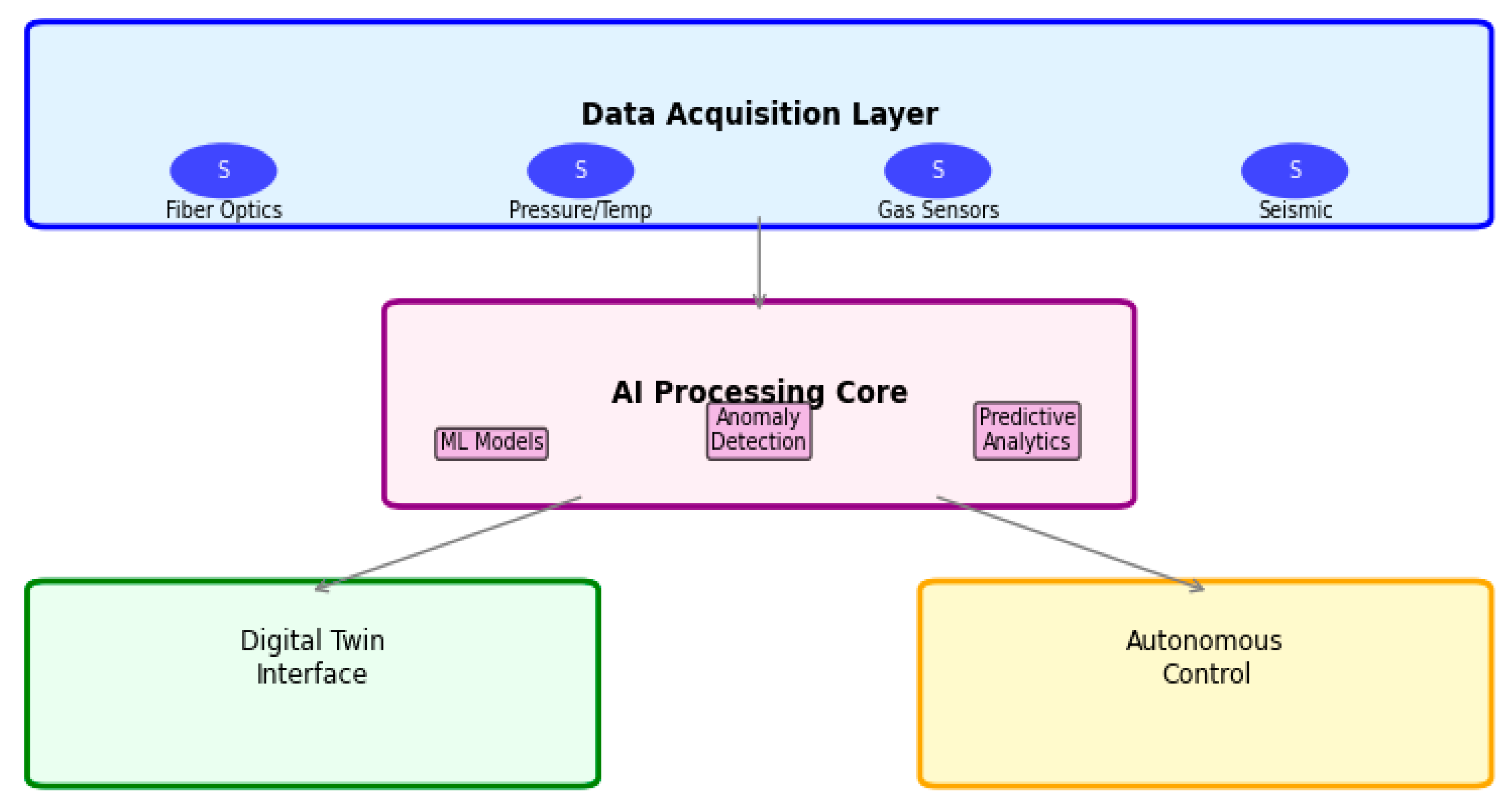
The operational intricacy and multifaceted characteristics of subterranean hydrogen storage pose considerable difficulties for traditional modeling and control systems. AI and ML have the power to change the way UHS works, make it safer, and allow for predictive management of all sorts of storage. AI algorithms can optimize the injection and withdrawal cycles for salt caverns by looking at real-time data on cavern pressure, temperature, and surface deformation. This helps to reduce volume loss caused by creep and extend the life of the cavern. In depleted reservoirs and saline aquifers, where fluid dynamics involve complex multiphase interactions with geochemical and microbial components, ML-powered coupled-process digital twins can predict hydrogen migration, purity loss, and microbial activity with greater accuracy than traditional reservoir simulators. These models can use data from fiber-optic sensors spread out over a large area, downhole fluid samples, and surface monitoring arrays to send out early warnings of dangers to containment or performance loss, as illustrated in Figure 3. AI-powered anomaly detection systems may constantly look at data from strain gauges, gas composition sensors, and groundwater monitors in lined rock caverns to find early symptoms of liner fatigue or seal failure.

5. Concluding Remarks

This research examined the technical, economic, and environmental feasibility of storing hydrogen underground in salt caverns, lined rock caverns, depleted hydrocarbon reservoirs, and saline aquifers. Based on storage capacity, injectivity, geological integrity, cyclic deliverability, and long-term sustainability, each geological formation has its own pros and cons.
Salt caverns are the best choice for short-term, frequent storage because they offer the highest cycle efficiency, the fastest discharge rates, and the lowest risk of contamination. Their main problems are that they are hard to find and that solution mining uses a lot of water. Lined rock caverns are a good option when salt formations are not available, but sealing performance, hydrogen embrittlement, and high construction costs still make them hard to use on a large scale.
Depleted reservoirs and saline aquifers are the best places to store significant amounts of water for a long time. Depleted oil and gas fields offer proven containment, mature data availability, and existing infrastructure, making it easy to implement at low cost. Saline aquifers have the most promise worldwide, as they have abundant pore space and are found throughout the world. However, we need to manage better how H2, rock, and microbes interact, optimize cushion gas, and develop new ways to monitor them.
Addressing geomechanical risks, microbial activity, material compatibility, and cushion gas strategies is essential for advancing UHS to commercial scale. Geomechanical characterization under cyclic stresses, quantification and mitigation of microbial consumption and geochemical reactions, liner and wellbore material development to avoid embrittlement, and integrated techno-economic assessment of cushion gas management, monitoring strategies, and environmental protection are priorities. These improvements make UHS a key part of large-scale renewable energy storage, thereby stabilizing the grid and helping the world move toward a hydrogen economy with no net carbon emissions.

Author Contributions

Conceptualization and methodology, H.K.H.; formal analysis and investigation, L.L.A.; resources, S.R.O.; writing—original draft preparation, H.K.H.; writing—review and editing, L.L.A.; supervision, S.R.O.; project administration L.L.A. All authors have read and agreed to the published version of the manuscript.

Funding

This research received no external funding.

Data Availability Statement

No new data were created or analyzed in this study.

Conflicts of Interest

The authors declare no conflicts of interest.

References

  1. Zeng, L.; Sarmadivaleh, M.; Saeedi, A.; Chen, Y.; Zhong, Z.; Xie, Q. Storage Integrity during Underground Hydrogen Storage in Depleted Gas Reservoirs. Earth-Sci. Rev. 2023, 247, 104625. [Google Scholar] [CrossRef]
  2. Fatah, A.; Al-Yaseri, A. Geomechanical Integrity and Geochemical Reactions of Shale Caprocks for Hydrogen Storage: A Comprehensive Review. Fuel 2025, 400, 135728. [Google Scholar] [CrossRef]
  3. Jahanbakhsh, A.; Louis Potapov-Crighton, A.; Mosallanezhad, A.; Tohidi Kaloorazi, N.; Maroto-Valer, M.M. Underground Hydrogen Storage: A UK Perspective. Renew. Sustain. Energy Rev. 2024, 189, 114001. [Google Scholar] [CrossRef]
  4. Dafedar, A.A.; Verma, S.S.; Yadav, A. Hydrogen Storage Techniques for Stationary and Mobile Applications: A Review. In Recent Advances in Sustainable Technologies: Select Proceedings of ICAST 2020; Springer: Singapore, 2021; pp. 29–40. [Google Scholar] [CrossRef]
  5. Zhang, T.; Uratani, J.; Huang, Y.; Xu, L.; Griffiths, S.; Ding, Y. Hydrogen Liquefaction and Storage: Recent Progress and Perspectives. Renew. Sustain. Energy Rev. 2023, 176, 113204. [Google Scholar] [CrossRef]
  6. Drawer, C.; Lange, J.; Kaltschmitt, M. Metal Hydrides for Hydrogen Storage—Identification and Evaluation of Stationary and Transportation Applications. J. Energy Storage 2024, 77, 109988. [Google Scholar] [CrossRef]
  7. Kim, H.; So, S.H.; Muhammad, R.; Oh, H. Comparing the Practical Hydrogen Storage Capacity of Porous Adsorbents: Activated Carbon and Metal-Organic Framework. Int. J. Hydrogen Energy 2024, 50, 1616–1625. [Google Scholar] [CrossRef]
  8. Muhammed, N.S.; Haq, M.B.; Al Shehri, D.A.; Al-Ahmed, A.; Rahman, M.M.; Zaman, E.; Iglauer, S. Hydrogen Storage in Depleted Gas Reservoirs: A Comprehensive Review. Fuel 2023, 337, 127032. [Google Scholar] [CrossRef]
  9. Hawez, H.; Ahmed, Z. Enhanced Oil Recovery by CO2 Injection in Carbonate Reservoirs. WIT Trans. Ecol. Environ. 2014, 186, 547–558. [Google Scholar] [CrossRef]
  10. Oni, B.A.; Bade, S.O.; Sanni, S.E.; Orodu, O.D. Underground Hydrogen Storage in Salt Caverns: Recent Advances, Modeling Approaches, Barriers, and Future Outlook. J. Energy Storage 2025, 107, 114951. [Google Scholar] [CrossRef]
  11. Masoudi, M.; Hassanpouryouzband, A.; Hellevang, H.; Haszeldine, R.S. Lined Rock Caverns: A Hydrogen Storage Solution. J. Energy Storage 2024, 84, 110927. [Google Scholar] [CrossRef]
  12. Ramesh Kumar, K.; Honorio, H.; Chandra, D.; Lesueur, M.; Hajibeygi, H. Comprehensive Review of Geomechanics of Underground Hydrogen Storage in Depleted Reservoirs and Salt Caverns. J. Energy Storage 2023, 73, 108912. [Google Scholar] [CrossRef]
  13. Alms, K.; Ahrens, B.; Graf, M.; Nehler, M. Linking Geological and Infrastructural Requirements for Large-Scale Underground Hydrogen Storage in Germany. Front. Energy Res. 2023, 11, 1172003. [Google Scholar] [CrossRef]
  14. Hawez, H.; Sanaee, R.; Faisal, N.H. Multiphase Flow Modelling in Fractured Reservoirs Using a Novel Computational Fluid Dynamics Approach. In Proceedings of the 55th U.S. Rock Mechanics/Geomechanics Symposium 2021, Virtual, 20–23 June 2021; Volume 1. [Google Scholar]
  15. Hawez, H.K.; Asim, T.; Fazio, M. A Fully Coupled Model for Predicting Geomechanical and Multiphase Flow Behaviour in Fractured Rocks. Unconv. Resour. 2024, 4, 100105. [Google Scholar] [CrossRef]
  16. Muhammed, N.S.; Haq, B.; Al Shehri, D.; Al-Ahmed, A.; Rahman, M.M.; Zaman, E. A Review on Underground Hydrogen Storage: Insight into Geological Sites, Influencing Factors and Future Outlook. Energy Rep. 2022, 8, 461–499. [Google Scholar] [CrossRef]
  17. Qian, X.; You, S.; Wang, R.; Yue, Y.; Liao, Q.; Dai, J.; Tian, S.; Liu, X. Underground Hydrogen Storage in Salt Cavern: A Review of Advantages, Challenges, and Prospects. Sustainability 2025, 17, 5900. [Google Scholar] [CrossRef]
  18. Huang, S.; Li, Y.; Shi, X.; Bai, W.; Huang, Y.; Hong, Y.; Liu, X.; Ma, H.; Li, P.; Xu, M.; et al. The Role of Underground Salt Caverns in Renewable Energy Peaking: A Review. Energies 2024, 17, 6005. [Google Scholar] [CrossRef]
  19. Liu, W.; Li, Q.; Yang, C.; Shi, X.; Wan, J.; Jurado, M.J.; Li, Y.; Jiang, D.; Chen, J.; Qiao, W.; et al. The Role of Underground Salt Caverns for Large-Scale Energy Storage: A Review and Prospects. Energy Storage Mater. 2023, 63, 103045. [Google Scholar] [CrossRef]
  20. Asim, T.; Hawez, H.K. Effects of CO2 Geosequestration on Opalinus Clay. Energies 2024, 17, 2431. [Google Scholar] [CrossRef]
  21. Vandeginste, V.; Ji, Y.; Buysschaert, F.; Anoyatis, G. Mineralogy, Microstructures and Geomechanics of Rock Salt for Underground Gas Storage. Deep Undergr. Sci. Eng. 2023, 2, 129–147. [Google Scholar] [CrossRef]
  22. Peppas, A.; Kottaridis, S.; Politi, C. Potential Application of RES and Underground H2 Storage in Abandoned Mines. Mater. Proc. 2023, 15, 30. [Google Scholar] [CrossRef]
  23. Yang, M.; Chai, M.; Yuan, S.; Feng, T.; Wang, S.; Zhang, J.; Feng, Q.; Chen, Z.; Wei, T.; Wu, G.; et al. In-Situ Combustion for Heavy Oil and Oil Sands Recovery: Recent Progress, Field Applications, and Future Perspectives. Energy Fuels 2024, 38, 10395–10420. [Google Scholar] [CrossRef]
  24. Yousefi, S.H.; Groenenberg, R.; Koornneef, J.; Juez-Larré, J.; Shahi, M. Techno-Economic Analysis of Developing an Underground Hydrogen Storage Facility in Depleted Gas Field: A Dutch Case Study. Int. J. Hydrogen Energy 2023, 48, 28824–28842. [Google Scholar] [CrossRef]
  25. Talukdar, M.; Blum, P.; Heinemann, N.; Miocic, J. Techno-Economic Analysis of Underground Hydrogen Storage in Europe. iScience 2024, 27, 108771. [Google Scholar] [CrossRef]
  26. Huang, J.; Ge, X.; Ma, H.; Shi, X.; Li, Y. The Development, Current Status and Challenges of Salt Cavern Hydrogen Storage Technology in China. Energies 2025, 18, 1044. [Google Scholar] [CrossRef]
  27. Liu, J.; Pei, J.; Wei, J.; Yang, J.; Xu, H. Development Status and Prospect of Salt Cavern Energy Storage Technology. Earth Energy Sci. 2025, 1, 159–179. [Google Scholar] [CrossRef]
  28. Hawez, H.K.; Asim, T. Effects of Externally Applied Stress on Multiphase Flow Characteristics in Naturally Fractured Tight Reservoirs. Appl. Sci. 2024, 14, 8540. [Google Scholar] [CrossRef]
  29. Panfilov, M. Underground and Pipeline Hydrogen Storage. In Compendium of Hydrogen Energy: Hydrogen Storage, Distribution and Infrastructure: Volume 2; Elsevier Ltd.: Amsterdam, The Netherlands, 2015; pp. 91–115. ISBN 9781782423621. [Google Scholar]
  30. Rayhana, R.; Xiao, G.; Liu, Z. Fiber-Optic Sensing Technologies for Underground Pipeline Monitoring. IEEE Open J. Instrum. Meas. 2025, 4, 7000217. [Google Scholar] [CrossRef]
  31. Höpken, L.; Bekebrok, H.; Pluta, A.; Langnickel, H.; Savchenko, I.; Ohm, M.; Steinmann, O.; Zobel, M.; Dyck, A.; Agert, C. Modelling Green Hydrogen Storage in Salt Caverns: Implications of Future Storage Demands on Cavern Operation. J. Energy Storage 2025, 119, 116150. [Google Scholar] [CrossRef]
  32. Poda, S.; Talal, G. Geomechanical and Geochemical Considerations for Hydrogen Storage in Shale and Tight Reservoirs. Processes 2025, 13, 2522. [Google Scholar] [CrossRef]
  33. Hasii, O.; Gasii, G. Coal Mining and Water Resources: Impacts, Challenges, and Strategies for Sustainable Environmental Management. IOP Conf. Ser. Earth Environ. Sci. 2024, 1348, 012017. [Google Scholar] [CrossRef]
  34. Wu, T.; Fu, X.; Liu, B.; Wang, H.; Xie, Z.; Pan, Z. Mechanical Behavior and Damage-Induced Permeability Evolution of Mudstone and Gypsum Caprocks. J. Pet. Sci. Eng. 2021, 196, 108079. [Google Scholar] [CrossRef]
  35. Fourmeau, M.; Liu, W.; Li, Z.; Nelias, D.; Fan, J.; Tian, H.; Liu, W. Research Status of Creep–Fatigue Characteristics of Salt Rocks and Stability of Compressed Air Storage in Salt Caverns. Earth Energy Sci. 2025, 1, 98–116. [Google Scholar] [CrossRef]
  36. Mielich, T.; Dobler, R.; Hollnagel, J.; Akca, O.; Müller-Kirchenbauer, J. Europe’s Way from Natural Gas to Green Hydrogen: Modeling and Simulation of the Transforming European Gas Transport Infrastructure. Int. J. Hydrogen Energy 2025, 135, 156–171. [Google Scholar] [CrossRef]
  37. Janßen, H.; Satola, B.; Kroener, M.; Dyck, A.; Vehse, M.; Wark, M.; Agert, C. Assessment of the Feasibility of Hydrogen Storage in Salt Caverns: Implications for Purity and Contamination Pathways for Fuel Cell Mobility. Int. J. Hydrogen Energy 2025, 170, 151236. [Google Scholar] [CrossRef]
  38. Amirthan, T.; Perera, M.S.A. The Role of Storage Systems in Hydrogen Economy: A Review. J. Nat. Gas Sci. Eng. 2022, 108, 104843. [Google Scholar] [CrossRef]
  39. Du, K.; Xie, J.; Khandelwal, M.; Zhou, J. Utilization Methods and Practice of Abandoned Mines and Related Rock Mechanics under the Ecological and Double Carbon Strategy in China—A Comprehensive Review. Minerals 2022, 12, 1065. [Google Scholar] [CrossRef]
  40. Andersson, J.; Grönkvist, S. Large-Scale Storage of Hydrogen. Int. J. Hydrogen Energy 2019, 44, 11901–11919. [Google Scholar] [CrossRef]
  41. Caglayan, D.G.; Weber, N.; Heinrichs, H.U.; Linßen, J.; Robinius, M.; Kukla, P.A.; Stolten, D. Technical Potential of Salt Caverns for Hydrogen Storage in Europe. Int. J. Hydrogen Energy 2020, 45, 6793–6805. [Google Scholar] [CrossRef]
  42. Tarkowski, R.; Uliasz-Misiak, B.; Tarkowski, P. Storage of Hydrogen, Natural Gas, and Carbon Dioxide—Geological and Legal Conditions. Int. J. Hydrogen Energy 2021, 46, 20010–20022. [Google Scholar] [CrossRef]
  43. Kabuth, A.; Dahmke, A.; Beyer, C.; Bilke, L.; Dethlefsen, F.; Dietrich, P.; Duttmann, R.; Ebert, M.; Feeser, V.; Görke, U.J.; et al. Energy Storage in the Geological Subsurface: Dimensioning, Risk Analysis and Spatial Planning: The ANGUS+ Project. Environ. Earth Sci. 2017, 76, 23. [Google Scholar] [CrossRef]
  44. Portarapillo, M.; Di Benedetto, A. Risk Assessment of the Large-Scale Hydrogen Storage in Salt Caverns. Energies 2021, 14, 2856. [Google Scholar] [CrossRef]
  45. Haddad, P.G.; Ranchou-Peyruse, M.; Guignard, M.; Mura, J.; Casteran, F.; Ronjon-Magand, L.; Senechal, P.; Isaure, M.P.; Moonen, P.; Hoareau, G.; et al. Geological Storage of Hydrogen in Deep Aquifers—An Experimental Multidisciplinary Study. Energy Environ. Sci. 2022, 15, 3400–3415. [Google Scholar] [CrossRef]
  46. Leng, G.; Yan, W.; Chen, Z.; Li, Z.; Liu, B.; Deng, P.; Zhang, C.; Liu, W.; Qi, H. Technical Challenges and Opportunities of Hydrogen Storage: A Comprehensive Review on Different Types of Underground Storage. J. Energy Storage 2025, 114, 115900. [Google Scholar] [CrossRef]
  47. Viswanathan, H.S.; Ajo-Franklin, J.; Birkholzer, J.T.; Carey, J.W.; Guglielmi, Y.; Hyman, J.D.; Karra, S.; Pyrak-Nolte, L.J.; Rajaram, H.; Srinivasan, G.; et al. From Fluid Flow to Coupled Processes in Fractured Rock: Recent Advances and New Frontiers. Rev. Geophys. 2022, 60, e2021RG000744. [Google Scholar] [CrossRef]
  48. Fibbi, G.; Del Soldato, M.; Fanti, R. Review of the Monitoring Applications Involved in the Underground Storage of Natural Gas and CO2. Energies 2023, 16, 12. [Google Scholar] [CrossRef]
  49. Hawez, H.K.; Asim, T. Impact of Regional Pressure Dissipation on Carbon Capture and Storage Projects: A Comprehensive Review. Energies 2024, 17, 1889. [Google Scholar] [CrossRef]
  50. Mehr, A.S.; Phillips, A.D.; Brandon, M.P.; Pryce, M.T.; Carton, J.G. Recent Challenges and Development of Technical and Technoeconomic Aspects for Hydrogen Storage, Insights at Different Scales; A State of Art Review. Int. J. Hydrogen Energy 2024, 70, 786–815. [Google Scholar] [CrossRef]
  51. Rathnayaka, R.I.A.; Ranjith, P.G. Hydrogen Storage in Unlined Rock Caverns: An Insight on Opportunities and Challenges. Int. J. Hydrogen Energy 2024, 72, 1023–1037. [Google Scholar] [CrossRef]
  52. Hawez, H.K.; Bakir, H.; Jamal, K.; Kakakhan, M.; Hussein, K.; Omar, M. Numerical Investigation of CO2 Injection Effects on Shale Caprock Integrity: A Case Study of Opalinus Clay. Gases 2025, 5, 15. [Google Scholar] [CrossRef]
  53. Tian, D.; Khaledi, K.; Jalali, M.; Amann, F. Long-Term Cyclic Thermo–Mechanical Behavior of Vertical and Horizontal Salt Caverns for Hydrogen Storage. J. Energy Storage 2025, 124, 116661. [Google Scholar] [CrossRef]
  54. Ekechukwu, O.M.; Asim, T.; Hawez, H.K. Recent Developments in Hydrocyclone Technology for Oil-in-Water Separation from Produced Water. Energies 2024, 17, 3181. [Google Scholar] [CrossRef]
  55. Zhou, Q.; Liu, D.; Lin, X. Pre-Evaluation of Fault Stability for Underground Mining Based on Geomechanical Fault-Slip Analysis. Geomat. Nat. Hazards Risk 2022, 13, 400–413. [Google Scholar] [CrossRef]
  56. Liu, W.; Pei, P. Evaluation of the Influencing Factors of Using Underground Space of Abandoned Coal Mines to Store Hydrogen Based on the Improved ANP Method. Adv. Mater. Sci. Eng. 2021, 2021, 7506055. [Google Scholar] [CrossRef]
  57. Hawez, H. Modeling of CO2 Injection in Gas Condensate Reservoirs; LAMBERT Academic Publishing: Saarbrücken, Germany, 2015; ISBN 978-3-659-70854-1. [Google Scholar]
  58. Campari, A.; Ustolin, F.; Alvaro, A.; Paltrinieri, N. A Review on Hydrogen Embrittlement and Risk-Based Inspection of Hydrogen Technologies. Int. J. Hydrogen Energy 2023, 48, 35316–35346. [Google Scholar] [CrossRef]
  59. Saadat, Z.; Farazmand, M.; Sameti, M. Integration of Underground Green Hydrogen Storage in Hybrid Energy Generation. Fuel 2024, 371, 131899. [Google Scholar] [CrossRef]
  60. Hu, Q.; Zhang, S.; Zhang, X.; Wang, F. Enhancing Disaster Prevention and Structural Resilience of Tunnels: A Study on Liquid Hydrogen Leakage, Diffusion, and Explosion Mitigation. Tunn. Undergr. Space Technol. 2025, 162, 106626. [Google Scholar] [CrossRef]
  61. Hou, B.; Shangguan, S.; Niu, Y.; Su, Y.; Yu, C.; Liu, X.; Li, Z.; Li, J.; Liu, X.; Zhao, K. Unique Properties of Rock Salt and Application of Salt Caverns on Underground Energy Storage: A Mini Review. Energy Sources Part A Recovery Util. Environ. Eff. 2024, 46, 621–635. [Google Scholar] [CrossRef]
  62. Wei, B.; Gao, L.; Zhao, H. Study on the Seismic Stability of Urban Sewage Treatment and Underground Reservoir of an Abandoned Mine Pumped Storage Power Station. Sustainability 2025, 17, 5620. [Google Scholar] [CrossRef]
  63. Tao, L.; Ju, Y. Hydrogen Storage Potential of Coal: Influence of Coal on Pore Structure and Adsorption Mechanisms. Front. Earth Sci. 2025, 13, 1589956. [Google Scholar] [CrossRef]
  64. Crotogino, F.; Schneider, G.S.; Evans, D.J. Renewable Energy Storage in Geological Formations. Proc. Inst. Mech. Eng. Part A J. Power Energy 2018, 232, 100–114. [Google Scholar] [CrossRef]
  65. Cheng, Q.; Zhang, R.; Shi, Z.; Lin, J. Review of Common Hydrogen Storage Tanks and Current Manufacturing Methods for Aluminium Alloy Tank Liners. Int. J. Light. Mater. Manuf. 2023, 7, 269–284. [Google Scholar] [CrossRef]
  66. Johansson, F.; Spross, J.; Damasceno, D.; Johansson, J.; Stille, H. Investigation of Research Needs Regarding the Storage of Hydrogen Gas in Lined Rock Caverns Prestudy for Work Package 2.3 in HYBRIT Research Program 1. Tech. Rep. 2018 KTH R. Inst. Technol. 2018. Available online: https://api.semanticscholar.org/CorpusID:49309570 (accessed on 31 December 2025).
  67. Patanwar, Y.K.; Kim, H.M.; Deb, D.; Gujjala, Y.K. Underground Storage of Hydrogen in Lined Rock Caverns: An Overview of Key Components and Hydrogen Embrittlement Challenges. Int. J. Hydrogen Energy 2023, 50, 116–133. [Google Scholar] [CrossRef]
  68. Yin, J.-H.; Zhou, W.-H. Influence of Grouting Pressure and Overburden Stress on the Interface Resistance of a Soil Nail. J. Geotech. Geoenviron. Eng. 2009, 135, 1198–1208. [Google Scholar] [CrossRef]
  69. Boon, M.; Hajibeygi, H. Experimental Characterization of H2/Water Multiphase Flow in Heterogeneous Sandstone Rock at the Core Scale Relevant for Underground Hydrogen Storage (UHS). Sci. Rep. 2022, 12, 14604. [Google Scholar] [CrossRef] [PubMed]
  70. Chen, F.; Ma, Z.; Nasrabadi, H.; Chen, B.; Saad Mehana, M.Z.; Van Wijk, J. Capacity Assessment and Cost Analysis of Geologic Storage of Hydrogen: A Case Study in Intermountain-West Region USA. Int. J. Hydrogen Energy 2023, 48, 9008–9022. [Google Scholar] [CrossRef]
  71. Wang, M.; Chen, Y.; Song, G.; Liu, H.; Wang, Y.; Zhang, P.; Qiu, Y.; Chen, T.; Li, J.; Liu, X.; et al. Features of the Early Hydrocarbon Accumulation and Its Effects on the Late Accumulation in Sandstone Reservoir: A Case Study of the Eocene Dongying Depression, Bohai Bay Basin. Front. Earth Sci. 2022, 10, 915747. [Google Scholar] [CrossRef]
  72. Szott, W.; Miłek, K. Analysis of Reservoir Fluid Migration in the Process of CO2 Sequestration in a Partially Depleted Gas Reservoir. Energies 2021, 14, 6398. [Google Scholar] [CrossRef]
  73. Jafari Raad, S.M.; Leonenko, Y.; Hassanzadeh, H. Hydrogen Storage in Saline Aquifers: Opportunities and Challenges. Renew. Sustain. Energy Rev. 2022, 168, 112846. [Google Scholar] [CrossRef]
  74. Al-Shafi, M.; Massarweh, O.; Abushaikha, A.S.; Bicer, Y. A Review on Underground Gas Storage Systems: Natural Gas, Hydrogen and Carbon Sequestration. Energy Rep. 2023, 9, 6251–6266. [Google Scholar] [CrossRef]
  75. Hawez, H.K.; Asaad, F.; Suleiman, A.; Khorsheed, A. Modeling Fluid Dynamics in Porous Media: A Pore-Scale Flow Analysis. 2025. [Google Scholar] [CrossRef]
  76. Sadkhan, R.A.; Al-Mudhafar, W.J. Key Aspects of Underground Hydrogen Storage in Depleted Hydrocarbon Reservoirs and Saline Aquifers: A Review and Understanding. Energy Geosci. 2024, 5, 100339. [Google Scholar] [CrossRef]
  77. Cui, C.; Qian, Y.; Ren, K.; Wu, Z. Optimizing Storage Parameters for Underground Hydrogen Storage in Aquifers: Cushion Gas Selection, Well Pattern Design, and Purity Control. Appl. Sci. 2025, 3, 11348. [Google Scholar] [CrossRef]
  78. Dilshan, R.A.D.P.; Perera, M.S.A.; Matthai, S.K. Effect of Mechanical Weakening and Crack Formation on Caprock Integrity during Underground Hydrogen Storage in Depleted Gas Reservoirs—A Comprehensive Review. Fuel 2024, 371, 131893. [Google Scholar] [CrossRef]
  79. Williams, R.; Crandall, R.S.; Bloom, A. Use of Carbon Dioxide in Energy Storage. Appl. Phys. Lett. 1978, 33, 381–383. [Google Scholar] [CrossRef]
  80. Ali, A.; Alsubaih, S.; Sepehrnoori, K.; Delshad, M. A Comprehensive Review of Well Integrity Challenges and Digital Twin Applications Across Conventional, Unconventional, and Storage Wells. Energies 2025, 18, 4757. [Google Scholar] [CrossRef]
  81. Opoku Duartey, K.; Ampomah, W.; Rahnema, H.; Mehana, M. Underground Hydrogen Storage: Transforming Subsurface Science into Sustainable Energy Solutions. Energies 2025, 18, 748. [Google Scholar] [CrossRef]
  82. Lankof, L.; Tarkowski, R. Assessment of the Potential for Underground Hydrogen Storage in Bedded Salt Formation. Int. J. Hydrogen Energy 2020, 45, 19479–19492. [Google Scholar] [CrossRef]
  83. Elberry, A.M.; Thakur, J.; Santasalo-Aarnio, A.; Larmi, M. Large-Scale Compressed Hydrogen Storage as Part of Renewable Electricity Storage Systems. Int. J. Hydrogen Energy 2021, 46, 15671–15690. [Google Scholar] [CrossRef]
  84. Hawez, H.K.; Sanaee, R.; Faisal, N.H. A Critical Review on Coupled Geomechanics and Fluid Flow in Naturally Fractured Reservoirs. J. Nat. Gas Sci. Eng. 2021, 95, 104150. [Google Scholar] [CrossRef]
  85. Naderloo, M.; Ramesh Kumar, K.; Hernandez, E.; Hajibeygi, H.; Barnhoorn, A. Experimental and Numerical Investigation of Sandstone Deformation under Cycling Loading Relevant for Underground Energy Storage. J. Energy Storage 2023, 64, 107198. [Google Scholar] [CrossRef]
  86. Epelle, E.I.; Obande, W.; Udourioh, G.A.; Afolabi, I.C.; Desongu, K.S.; Orivri, U.; Gunes, B.; Okolie, J.A. Perspectives and Prospects of Underground Hydrogen Storage and Natural Hydrogen. Sustain. Energy Fuels 2022, 6, 3324–3343. [Google Scholar] [CrossRef]
  87. Yang, C.; Wang, T.; Chen, H. Theoretical and Technological Challenges of Deep Underground Energy Storage in China. Engineering 2023, 25, 168–181. [Google Scholar] [CrossRef]
  88. Harati, S.; Rezaei Gomari, S.; Gasanzade, F.; Bauer, S.; Pak, T.; Orr, C. Underground Hydrogen Storage to Balance Seasonal Variations in Energy Demand: Impact of Well Configuration on Storage Performance in Deep Saline Aquifers. Int. J. Hydrogen Energy 2023, 48, 26894–26910. [Google Scholar] [CrossRef]
  89. Xu, C.; Zhang, G.; Xia, C.; Du, S. Mechanical Behavior of a New Segmented Lining for Underground Rock Caverns with High Internal Pressure. Comput. Geotech. 2024, 167, 106100. [Google Scholar] [CrossRef]
  90. Rolo, I.; Costa, V.A.F.; Brito, F.P. Hydrogen-Based Energy Systems: Current Technology Development Status, Opportunities and Challenges. Energies 2024, 17, 180. [Google Scholar] [CrossRef]
  91. Cai, R.; Ma, H.; Liang, X.; Zhao, K.; Yang, C. Allowable Pillar Width for Salt Cavern Gas Storage Based on Triangular Well Layout: A Case Study in China. Energies 2024, 17, 324. [Google Scholar] [CrossRef]
  92. Tarkowski, R.; Lankof, L.; Luboń, K.; Michalski, J. Hydrogen Storage Capacity of Salt Caverns and Deep Aquifers versus Demand for Hydrogen Storage: A Case Study of Poland. Appl. Energy 2024, 355, 122268. [Google Scholar] [CrossRef]
  93. Diamantakis, N.; Peecock, A.; Shahrokhi, O.; Pitchaimuthu, S. Review Article A Review of Analogue Case Studies Relevant to Large-Scale Underground Hydrogen Storage. Energy Rep. 2024, 11, 2374–2400. [Google Scholar] [CrossRef]
  94. Safari, A.; Zeng, L.; Nguele, R.; Sugai, Y.; Sarmadivaleh, M. Review on Using the Depleted Gas Reservoirs for the Underground H2 Storage: A Case Study in Niigata Prefecture, Japan. Int. J. Hydrogen Energy 2023, 48, 10579–10602. [Google Scholar] [CrossRef]
  95. Quintos Fuentes, J.E.; Santos, D.M.F. Technical and Economic Viability of Underground Hydrogen Storage. Hydrogen 2023, 4, 975–1000. [Google Scholar] [CrossRef]
  96. Aslannezhad, M.; Ali, M.; Kalantariasl, A.; Sayyafzadeh, M.; You, Z.; Iglauer, S.; Keshavarz, A. A Review of Hydrogen/Rock/Brine Interaction: Implications for Hydrogen Geo-Storage. Prog. Energy Combust. Sci. 2023, 95, 101066. [Google Scholar] [CrossRef]
  97. Małachowska, A.; Łukasik, N.; Mioduska, J.; Gębicki, J. Hydrogen Storage in Geological Formations—The Potential of Salt Caverns. Energies 2022, 15, 5038. [Google Scholar] [CrossRef]
  98. Wang, T.; Yan, X.; Yang, H.; Yang, X.; Jiang, T.; Zhao, S. A New Shape Design Method of Salt Cavern Used as Underground Gas Storage. Appl. Energy 2013, 104, 50–61. [Google Scholar] [CrossRef]
  99. Bo, Z.; Zeng, L.; Chen, Y.; Xie, Q. Geochemical Reactions-Induced Hydrogen Loss during Underground Hydrogen Storage in Sandstone Reservoirs. Int. J. Hydrogen Energy 2021, 46, 19998–20009. [Google Scholar] [CrossRef]
  100. Yekta, A.E.; Pichavant, M.; Audigane, P. Evaluation of Geochemical Reactivity of Hydrogen in Sandstone: Application to Geological Storage. Appl. Geochem. 2018, 95, 182–194. [Google Scholar] [CrossRef]
  101. Gómez, J.A.; Santos, D.M.F. The Status of On-Board Hydrogen Storage in Fuel Cell Electric Vehicles. Designs 2023, 7, 97. [Google Scholar] [CrossRef]
  102. Klopčič, N.; Grimmer, I.; Winkler, F.; Sartory, M.; Trattner, A. A Review on Metal Hydride Materials for Hydrogen Storage. J. Energy Storage 2023, 72, 108456. [Google Scholar] [CrossRef]
  103. Marouani, I.; Guesmi, T.; Alshammari, B.M.; Alqunun, K.; Alzamil, A.; Alturki, M.; Hadj Abdallah, H. Integration of Renewable-Energy-Based Green Hydrogen into the Energy Future. Processes 2023, 11, 2685. [Google Scholar] [CrossRef]
Figure 1. H2 loss pathway in porous media.
Energies 19 02760 g001
Figure 2. Comparative performance analysis.
Energies 19 02760 g002
Figure 3. AI-Integrated smart monitoring system.
Energies 19 02760 g003
Table 1. Evaluation criteria for UHS technologies.
CriteriaDescription
Geological IntegrityCaprock quality, seal strength, permeability
Storage Capacity & ScaleStorage volume (GWh–TWh), scalability potential
Cyclic PerformanceFrequency of injection/withdrawal cycles
Hydrogen Purity RetentionEffect of storage on hydrogen quality
Technology Maturity (TRL)Level of commercial or pilot readiness
Economic FeasibilityCapital and operating costs, LCOHS
Environmental ImpactRisks such as leakage, brine disposal, and microbial effects
Table 2. Comparison of four underground hydrogen storage methods by function, characteristics, and challenges.
Storage TypeFunctionCharacteristicsProblems
Salt CavernsArtificial salt caverns for pure H2 storage
  • High purity
  • Rapid cycling
  • Good seal
  • Salt basins
  • High cost
  • Water use
Lined Rock CavernsUse old mine voids for H2 storage
  • Existing voids
  • Low cost
  • Local to mines
  • Leakage risk
  • Structure weak
  • Gas mixing
Depleted ReservoirsReuse oil/gas reservoirs for bulk H2 storage
  • Existing wells
  • Known geology
  • Large volume
  • Contamination
  • Old wells leak
  • H2S risk
Saline AquifersNatural porous rock with water for H2 storage
  • Large capacity
  • Widely available
  • Lower cost
  • Seal uncertain
  • Microbial H2S
  • H2 solubility
Table 3. Technology Readiness and Deployment Status of UHS Methods.
Storage TypeTRL (2025)Example ProjectsDeployment Status
Salt Caverns8–9ACES (USA), Teesside (UK)Commercial
Lined Rock Caverns4–6HyBRIT (Sweden)Pilot
Depleted Reservoirs6–7Projects in the UK, Austria, The NetherlandsField Trials
Saline Aquifers2–4HyUsPRe (EU), Germany simulationsConceptual/Lab Stage
Table 4. Key characteristics, advantages, and limitations of salt caverns for UHS.
AspectDescriptionAdvantagesLimitations
Geological IntegrityVery low permeability (<1 × 10⁻²⁰ m2), self-healing capability.Excellent seal, minimal leakage risk, high safety.Limited to regions with suitable salt geology (salt domes, thick beds) [18]
Capacity & ScaleDepth: 500–2000 m; Volume: up to 1,000,000 m3 per cavern.High energy density (up to 300 kWhe/m3), suitable for GWh-scale storage.Total resource limited by salt deposit extent and thickness [18].
Cyclic PerformanceOperating pressure: 60–180 bar; capable of 6–12 complete cycles/year.Rapid injection/withdrawal, ideal for short-term (daily/weekly) grid balancing.Cavern creep and fatigue under frequent pressure cycling [21].
Hydrogen PurityMinimal interaction with rock matrix; purity retention > 99.8%.Retrieved H2 requires little to no purification, reducing operational cost.Brine residuals during construction may cause minor contamination [21].
Economic IndicatorsCAPEX: $1–2/m3 cavern volume; LCOHS: $0.39–2.41/kg H2.Most cost-effective UHS option compared to surface storage (80–90% cheaper).High upfront capital; water-intensive construction; brine disposal cost [22].
Environmental ImpactOperational leakage <0.05%/year; small surface footprint.Low lifecycle emissions; safe long-term containment.Significant water use and brine production during leaching phase [23].
Table 5. Distinct aspects of salt caverns for H2 storage.
AspectDescriptionReferences
Formation ProcessCreated through solution mining in salt domes or layered salt deposits.[3]
ImpermeabilityThe salt surrounding the cavern exhibits high impermeability to H2.[38]
Construction MethodConstructed by injecting water from the surface, eliminating the need for sinking shafts and tunneling.[39]
Cycle FlexibilityAllows for 6–12 storage cycles per year, accommodating short-term fluctuations in demand or supply.[40]
Preferred for UHSSalt caverns are favored for UHS due to their stable chemical characteristics and substantial capacities.[41]
Current ProjectsLarge-scale projects are underway in the UK, USA, Germany, and Poland.[13]
Industrial UtilizationStored H2 is used in industrial plants, aviation, and petrochemical facilities.[12]
Depth and SizeDepths up to 2000 m, heights of 300–500 m, and diameters of 50–100 m.[42]
Storage CapacityA single cavern can store up to approximately 1,000,000 cubic meters of H2.[43]
Density ChallengesH2’s low density (0.08988 g/L) presents storage challenges, requiring compression to enhance density.[44]
Operating PressureCaverns operate at 60 and 180 bar pressures, achieving energy densities of up to 300 kWhel/m3.[44]
Microbial ActivityLow risk is associated with microbial activity, but site-specific studies and monitoring are essential.[45]
Impact of BrineHigh salinity and brine content can reduce microbial diversity, but they require proper disposal or utilization.[45]
Table 7. Distinct aspects of rock caverns and abandoned mines.
AspectDescriptionReferences
Formation ProcessExcavation of caverns in igneous or metamorphic rocks, followed by steel or plastic liner encapsulation. Unused mines with large underground spaces can also be repurposed for H2 storage.[64]
Construction MethodMining and installing impermeable concrete liners involve significant expenses. Liners must withstand slight elastic or plastic deformations. When caverns are at shallow depths, water curtains may be required to store gases with low vapor pressure; at sufficient depths, hydrostatic pressure prevents fluid migration through fractures.[65]
Operational FlexibilityCapable of operating effectively under elevated pressure levels, accommodating multiple storage cycles throughout the year, making them suitable for peak-load demands. Storage facilities can be filled and drained dynamically at the same rate as H2 production.[43]
Current Applications and ProjectsUtilized for natural gas storage in Sweden. The HyBRIT project in Sweden is developing a pilot facility for H2 storage with a 100 cubic meter capacity, aiming to produce ‘green steel.’ Plans are underway for larger-scale facilities capable of storing up to 100,000–120,000 cubic meters of H2 gas, equivalent to 100 GWh of electricity, supporting significant sponge iron production for 3–4 days.[66]
Lined Rock Cavern (LRC) TechnologyLRCs feature interconnected layers, including a steel/polymer liner, a concrete liner, and a drainage system. The surrounding rock mass bears the load from high gas pressure, while the lining ensures gas-tight conditions and minimizes pressure on the lined rock cavern. LRCs offer greater versatility and site selection flexibility than traditional underground gas storage methods.[67]
Drainage SystemImplemented to counteract groundwater pressure during construction and operation, especially when storage pressure is lower than the natural hydrostatic pressure. Ensures safe storage by preventing water infiltration and maintaining structural integrity.[68]
Table 8. Key characteristics, advantages, and limitations of depleted reservoirs for UHS.
AspectDescriptionAdvantagesLimitations
Geological IntegrityProven caprock seal over geological/industrial time.High containment confidence; extensive historical data.H2’s smaller molecule/diffusivity may challenge seal [46].
Capacity & ScaleVery large pore volumes; GWh to multi-TWh scale.Largest single-site storage potential; seasonal storage.Effective capacity reduced by residual fluids & cushion gas [72].
Cyclic PerformanceRates constrained by reservoir permeability.Suitable for seasonal/strategic cycles (weeks/months).Low deliverability; prone to viscous fingering/gravity override [72].
Hydrogen PurityHigh risk of mixing with residual CH4 and microbial conversion.---Major purity loss concern; may require downstream separation [73].
Economic IndicatorsLow CAPEX (existing infra); LCOHS: $1.23/kg H2.Fastest deployment path; leverages “sunk-cost” assets.Costs for well re-completion, monitoring, gas separation [73].
Environmental ImpactReuses industrial footprint; potential for coupled CCS.Minimizes new disturbance; dual decarbonization service.Risk of geochemical reactions & mobilizing metals/microbes [74].
Table 9. Key characteristics, advantages, and limitations of saline aquifers for UHS.
AspectDescriptionAdvantagesLimitations
Geological IntegrityRequires proven regional seal; pristine structures.Theoretically high containment security; no legacy wells.Highest geological uncertainty; seal quality unknown [80].
Capacity & ScaleLargest global potential; multi-TWh scale.Abundant, widespread resource; continental-scale storage.Low recovery factor (20–50%); very high cushion gas need (up to 80%) [80].
Cyclic PerformanceInjection/withdrawal is slow, governed by Darcy flow.Suitable for very long-term (seasonal/annual) storage.Very low deliverability; unsuitable for frequent cycling [70].
Hydrogen PuritySignificant dissolution into brine; geochemical/bio reactions.---High risk of purity loss and hydrogen loss [70].
Economic IndicatorsCAPEX for new wells/characterization; LCOHS: ~$1.29/kg H2.Low intrinsic cost of pore space.Very high upfront characterization costs; large locked cushion gas capital [81].
Environmental ImpactNo hydrocarbon legacy; deep target zones.Minimal surface footprint; no operational brine production.Risk of altering deep biosphere; potential for induced seismicity [81].
Table 10. Synopsis of review articles regarding UHS.
TopicSpotlightReferences
A review on underground hydrogen storage: Insight into geological sites, influencing factors and future outlook
  • Hydrodynamics
  • Wettability
  • Capillary pressure
  • Diffusion Solubility
  • Adsorption
  • Chemical reactions
[16]
Perspectives and prospects of underground hydrogen storage and natural hydrogen
  • H2 production
  • Formation mechanisms
  • Geological locations
  • Serpentinization reactions
[86]
Storage integrity during underground hydrogen storage in depleted gas reservoirs
  • Depleted gas reservoirs
  • Storage Integrity
  • Geochemical reactions
  • Microbial activities
  • H2 cycling
[1]
Theoretical and Technological Challenges of Deep Underground Energy Storage in China
  • Energy reserves
  • Deep underground energy storage
  • Bedded rock salt
  • Salt cavern
  • Rock mechanics
[87]
Underground hydrogen storage to balance seasonal variations in energy demand: Impact of healthy configuration on storage performance in deep saline aquifers
  • Saline aquifer
  • Bunter sandstone formation
  • Well optimization
[88]
Comprehensive review of geomechanics of underground hydrogen storage in depleted reservoirs and salt caverns
  • Underground gas storage
  • Cyclic injection and production
  • Fault reactivation
  • Caprock and wellbore integrity
  • Experiments and modeling
  • Leakage
[12]
Underground hydrogen storage: A UK perspective
  • H2 strategy
  • Salt caverns
  • Saline aquifers
  • Depleted oil and gas reservoirs
[3]
Mechanical behavior of a new segmented lining for underground rock caverns with high internal pressure
  • Segmented lining
  • Retractable support
  • Underground cavern
  • Mechanical behavior
  • Stress path
[89]
Hydrogen-Based Energy Systems: Current Technology Development Status, Opportunities and Challenges
  • Environment
  • Large-scale energy storage
  • Storage costs
  • Storage facilities
[90]
Allowable Pillar Width for Salt Cavern Gas Storage Based on Triangular Well Layout: A Case Study in China
  • Rock salt
  • Pillar width
  • Triangular well pattern
  • Stability analysis
  • Numerical simulation
[91]
Hydrogen storage capacity of salt caverns and deep aquifers versus demand for hydrogen storage: A case study of Poland
  • Energy storage
  • Deep aquifers
  • Salt caverns
  • H2 storage needs
[92]
A review of analog case studies relevant to large-scale underground hydrogen storage
  • Town gas storage
  • Helium storage
  • North Sea gas reservoirs
[93]
Table 11. Operational envelopes and key performance indicators for UHS technologies.
CriterionSalt CavernsLined Rock CavernsDepleted ReservoirsSaline Aquifers
Typical Depth (m)500–2000 [64]100–500 [11]1000–3500 [80]1000–3000 [72]
Operating Pressure (bar)60–18050–150100–300100–250
Working Gas Recovery (%)95–9985–9550–8020–50
Cushion Gas Req. (% total)20–4020–4025–5050–80
Dominant Loss MechanismDiffusion through salt.Permeation through the liner.Mixing, dissolution, microbial.Dissolution, residual trapping.
Critical Material IssueWellhead/casing embrittlementLiner embrittlement & fatigue.Wellbore cement & casing.Wellbore materials.
TRL 8–9 (Commercial)4–6 (Pilot)6–7 (Pilot/Feasibility)2–4 (Conceptual/Lab)
Table 12. Roadmap for UHS development and integration (2025–2040).
PhaseYearsFocus Areas
I2025–2030Small-scale pilots, cushion gas R&D, geochemical & microbial studies.
II2030–2035Commercial testing, regulatory frameworks, sensor integration.
III2035–2040Full-scale hubs, AI-based optimization, grid integration.
Disclaimer/Publisher’s Note: The statements, opinions and data contained in all publications are solely those of the individual author(s) and contributor(s) and not of MDPI and/or the editor(s). MDPI and/or the editor(s) disclaim responsibility for any injury to people or property resulting from any ideas, methods, instructions or products referred to in the content.