


Abstract
Replacing traditional hydrocarbon fuel in aircraft turbine engines with hydrogen fuel contributes, in line with current trends, to reducing harmful carbon dioxide emissions and enabling increased flight altitude. Given the high research costs of full-scale turbine engines, research on miniature turbojet engines, due to their availability and relatively low modification costs, can play a significant role in better understanding and developing concepts for adapting existing hydrocarbon-based fuel systems to hydrogen fuel. This article presents the results of a comprehensive numerical analysis of the hydrogen combustion process—illustrating changes in its location and structure—for multiple variants of design changes to the combustion chamber of the miniature GTM-140 turbojet engine, primarily involving appropriate shaping of airflows through the holes in the glow tube and the location of the hydrogen injection point. Based on this analysis, a modernized combustion chamber geometry was proposed, which should ensure a stable hydrogen combustion process that is safe for the thermal resistance of the structural material—and structurally comparable to the baseline Jet-A1 hydrocarbon fuel combustion process. The obtained results can give ground for the construction and experimental testing of a hydrogen-powered turbine engine.
1. Introduction
The use of unmanned aerial vehicles (UAVs) has grown rapidly over the past two decades, making them popular tools for a wide range of applications in both civilian and defense sectors [1,2]. UAV propulsion technology is closely linked to flight performance and represents one of the most important developments in the aerospace industry. Although electric and propeller propulsion systems still dominate low-speed, long-duration missions, an increasing number of application scenarios—including rapid reconnaissance, target drones, expendable unmanned systems, and compact tactical platforms—demand higher speeds from their propulsion systems [3]. In this context, micro/miniature turbojet engines (MTEs), which have seen rapid development in recent years, can play an important role [4]. Compared to propeller propulsion, MTEs are no longer limited by propeller limitations; and their increasingly improved thrust-to-weight ratio allows for higher flight speeds for unmanned aerial vehicles [3,5,6]. It is worth noting that research on MTE, on the one hand, contributes to a beneficial improvement in their performance, and on the other hand, given their availability and relatively low redesign costs, enables preliminary testing of new solutions that could be applied to “full-scale” turbine engines, which are significantly more expensive to research. In particular, this may apply to attempts undertaken, as part of the general trend in aviation to reduce harmful exhaust emissions, not only to improve existing structures, but also to develop completely new solutions using a variety of alternative fuels as a way to meet these requirements. However, taking into account the differences in size scale and design differences, approximating the test results obtained for miniature engines to full-size engines should be carried out with great caution and care—it can only be a premise for possible changes [7,8].
One of the main options for achieving zero carbon dioxide emissions during turbine engine operation is to replace traditional hydrocarbon liquid fuel with hydrogen fuel [4,9,10,11,12,13,14]. Interest in using hydrogen as an energy source for aircraft propulsion dates back to the 1930s [15]. The reasons for addressing this issue have evolved over the years, starting from purely experimental, through research aimed at using hydrogen in military applications, and culminating in goals related to emissions of harmful substances, particularly CO2 [15,16,17,18,19,20,21]. Using hydrogen fuel to power MTEs can be an attractive alternative to conventional hydrocarbon fuels, improving their thermal efficiency (no delay resulting from fuel vaporization, rapid air mixing, and significantly faster flame propagation) and also significantly expands the combustion range (lower and upper combustion limits)—resulting in improved flight altitude [16]. However, given its specific properties, including a relatively high molecular diffusion coefficient, ensuring stable hydrogen combustion in turbine engine chambers remains a significant challenge for engineers [22,23,24,25]. In this context, due to its availability, relatively low prototyping and modification costs, and the ability to relatively quickly test subsequent MTEs variants, they can play a significant role in understanding and developing concepts for transforming existing designs. An additional advantage of this approach is the relatively short time between concept analysis based on CFD simulations and laboratory testing of individual components and the entire engine. This allows not only for understanding the physical phenomena but also for confirming their performance under more realistic test conditions. Therefore, the benefits of converting MTEs to hydrogen fuel are not limited to reducing harmful exhaust emissions and improving their efficiency and stability, but can also provide useful information for the design of full-scale hydrogen-powered engines.
This paper presents the results of a multivariate numerical analysis, based on which, following systematic elimination of design problems, an appropriate geometry of the combustor of a miniature turbojet engine was determined, which ensures stable and safe combustion of hydrogen fuel. The validation of numerical simulations was carried out indirectly, assuming their reliability based on the high agreement of the results of numerical simulations carried out for the combustion process of the standard JET-A1 fuel in MTEs with the experimental results.
2. Methodology for Performing Numerical Calculations
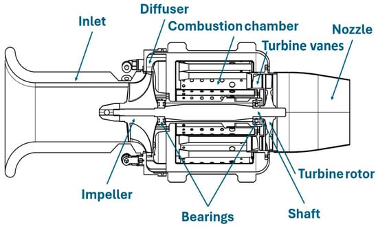
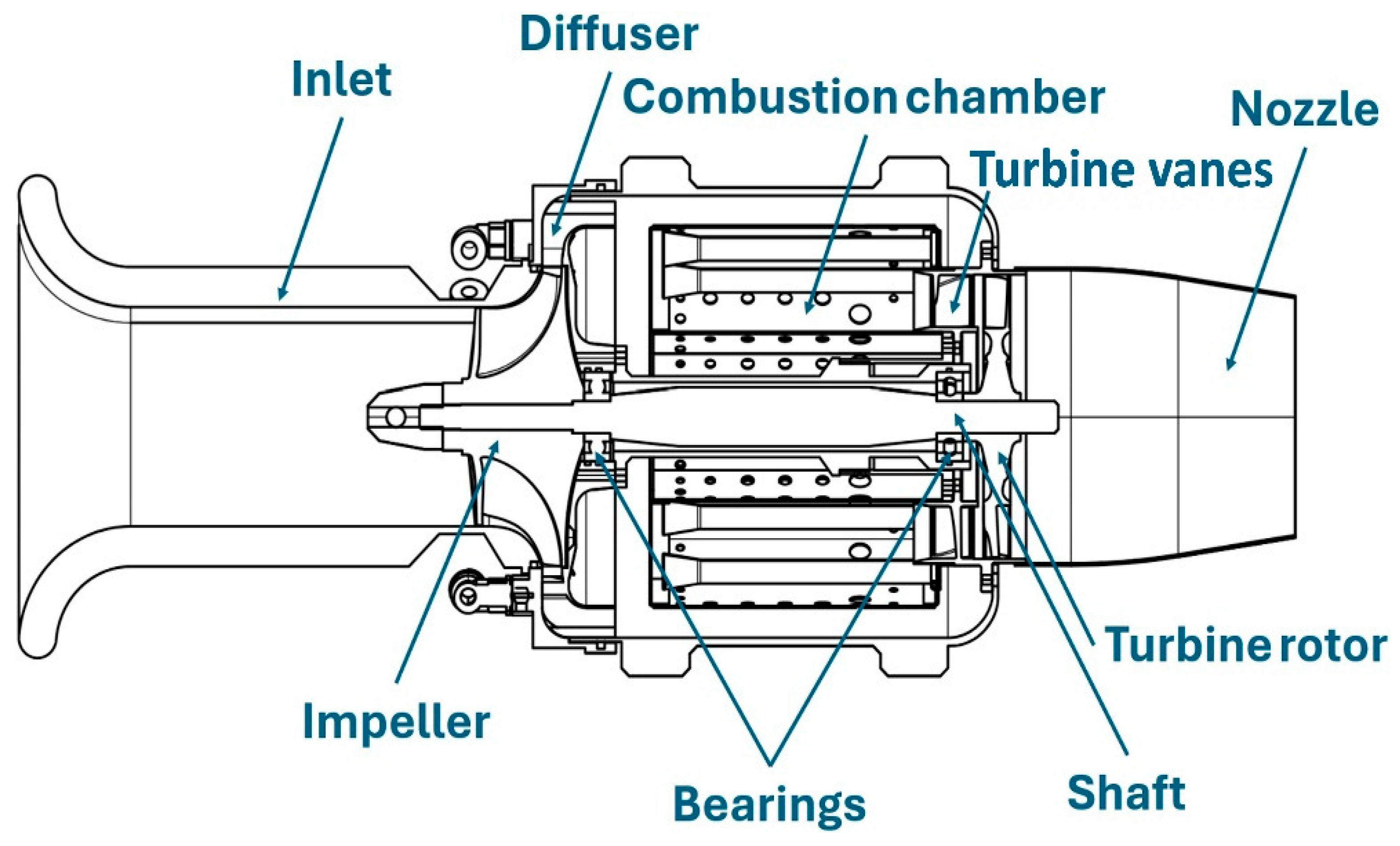
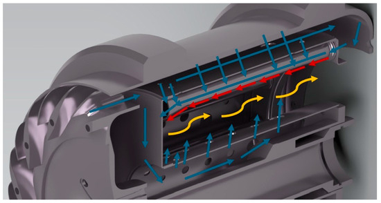
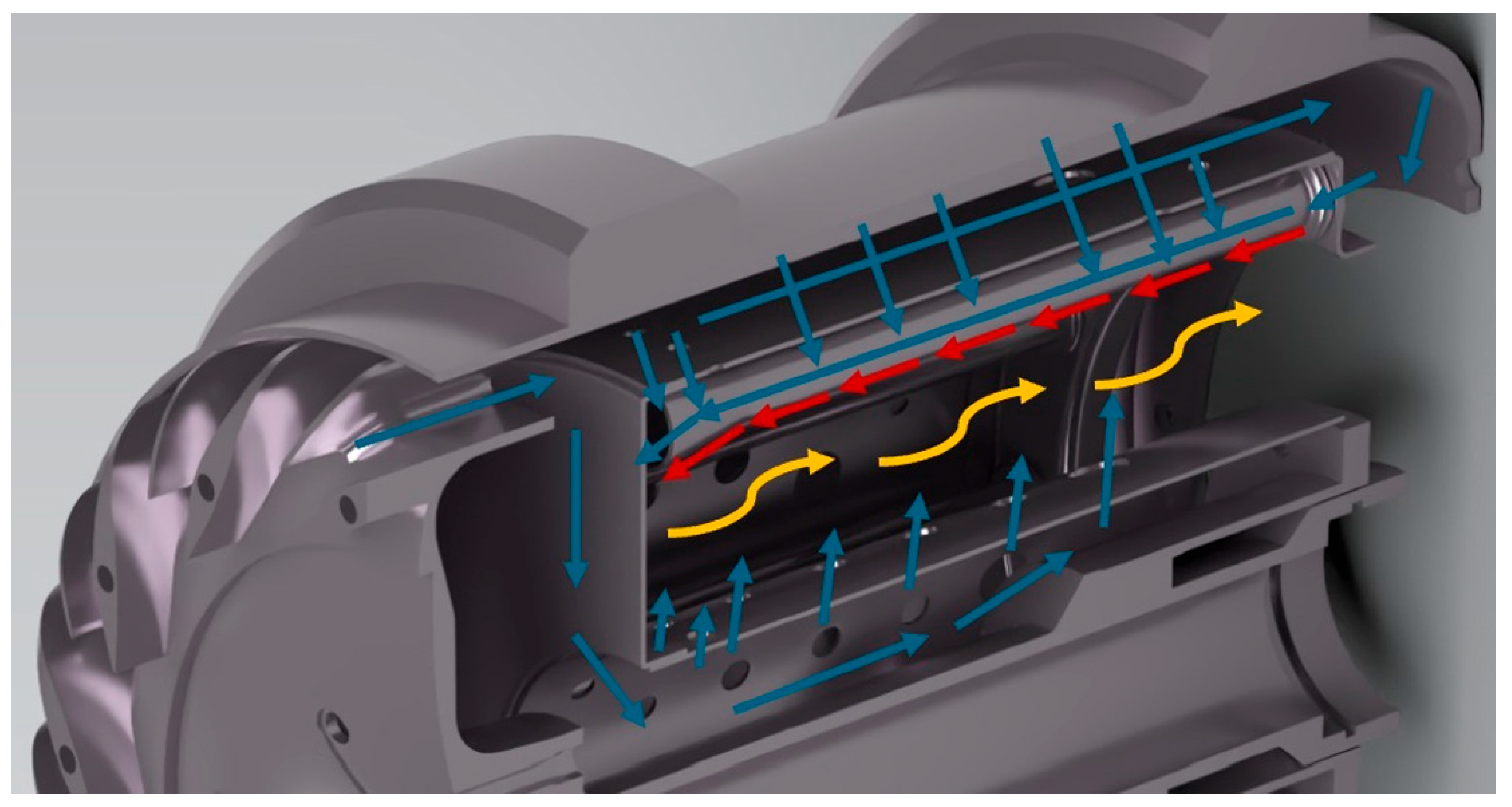
Numerical simulations of combustion processes in the combustor of the miniature turbojet engine GTM 140 (Figure 1 and Figure 2) were performed based on boundary conditions determined from experimental data (tests conducted using JET-A1 fuel), manufacturer’s specifications [26] and authors’ own calculations. The basic operating point was assumed to be the maximum shaft speed of 120k rpm, which, due to the highest fuel mass flow rate, also represents the point of greatest thermal load on the combustion chamber (Table 1).
Figure 1.
Schematic cross-section of the GTM 140 engine, showing its main components.
Figure 2.
Schematic diagram of air and fuel flow through the combustor of the GTM 140 miniature turbojet engine. Color code: blue for air, red for fuel, yellow for exhaust gases and the burning air-fuel mixture.
Table 1.
Parameters of the miniature GTM-140 turbine engine for the maximum shaft speed (120k rpm). Source: [26], authors’ own experimental tests.
The required hydrogen flow rate was calculated based on the equilibrium energy balance between hydrogen and Jet-A1 fuel:
where —fuel mass flow rate of Jet-A1 fuel, —fuel mass flow rate of hydrogen fuel, —lower heating value of Jet-A1, 43.6 MJ/kg; —lower heating value of hydrogen, 119.9 MJ/kg.
An additional assumption was the occurrence of a critical hydrogen flow through each of the 12 injector nozzles. The critical pressure ratio was determined using the relationship defining the ratio of the total pressure at the inlet to the pressure in the compressible flow at the outlet [27]:
where —total hydrogen pressure at the nozzle inlet, —total hydrogen pressure at the nozzle outlet—assumed to be equal to the actual pressure in the combustion chamber; —Mach number.
For κ = 1.41 and = 1
it follows that for each engine operating point the hydrogen fuel injection pressure should satisfy the following relationship:
and the relationship [27]:
where —contraction coefficient, —nozzle cross-sectional area, —compressibility coefficient, —total temperature in hydrogen flow; —individual gas constant for hydrogen.
It was determined that for a nozzle diameter of approximately 0.6 mm the total pressure that will ensure the appropriate mass flow of hydrogen for a rotational speed of 120k rpm is approximately 0.9 MPa, while for a speed of 80k rpm it is approximately 0.72 MPa. Under critical flow conditions (Ma = 1), the hydrogen stream reaches an average velocity of 1203 m/s for the assumed conditions. Providing critical flow through the orifice is beneficial for control system of the engine, prevents flame from propagating upstream of the injector to the fuel system, moves main combustion away from the point of injection and also makes fuel mass flow rate independent of local instantaneous pressure in the combustion chamber.
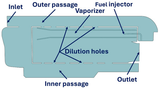
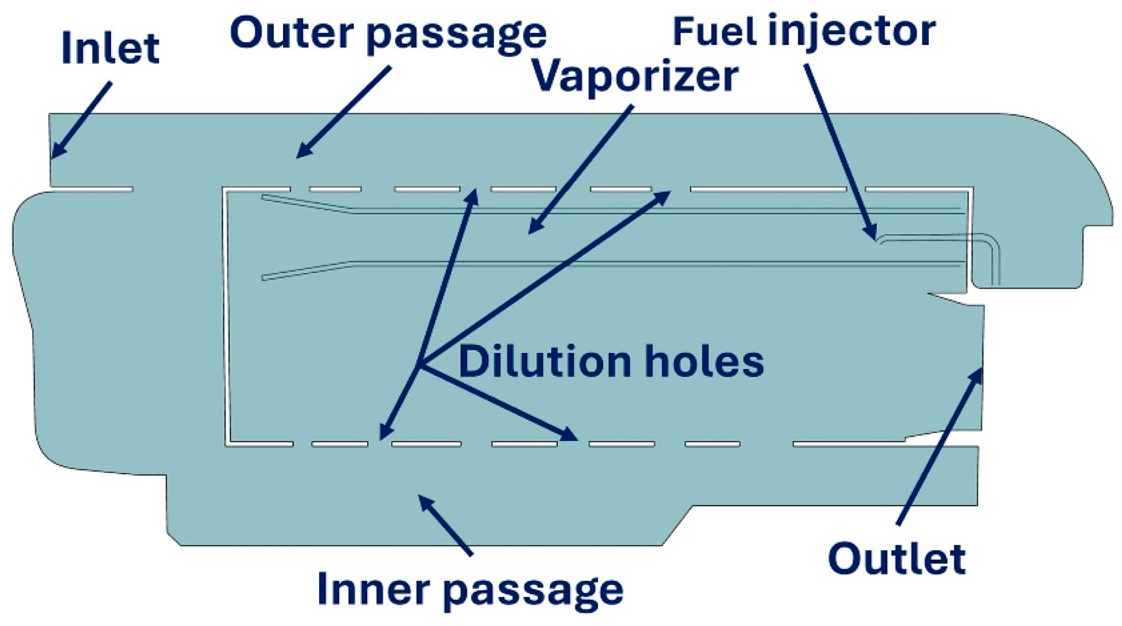
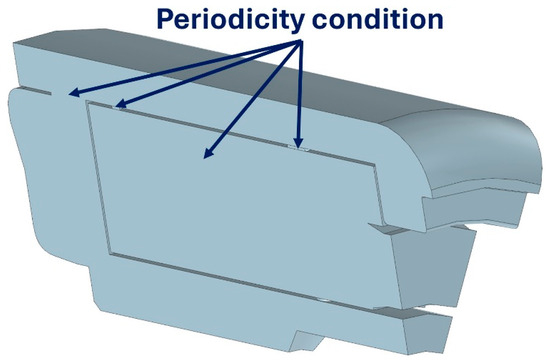
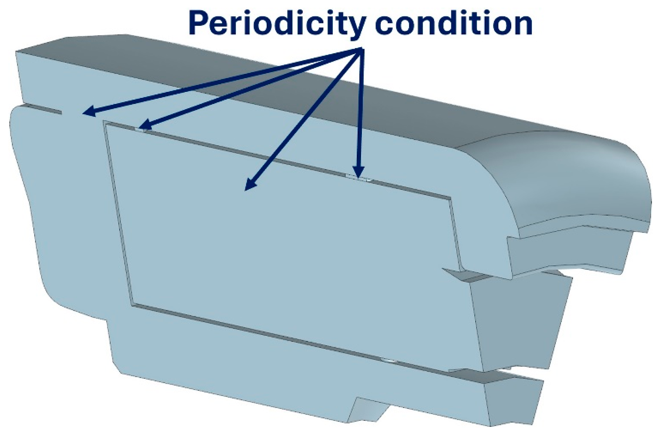
The vast majority of the numerical calculations concerned the hydrogen combustion process for various variants of the combustion chamber geometry. However, for comparative purposes, simulations were also carried out for a conventional configuration—powered by Jet-A1 fuel—using methods and models as similar as possible, minimizing the impact of differences in methodology on the results. The calculations were performed using ANSYS Fluent 2025R2 software, which allows for full integration of computational meshing and simulation operations. A three-dimensional fluid body model, created based on the manufacturer’s CAD model of the combustion chamber, was used for numerical calculations. Analyzing the geometry of the GTM 140 annular combustion chamber, it was determined that it was possible to reduce the computational domain to the smallest representative fragment of the chamber model with an aperture angle of 30°. A twelve-fold reduction in the computational domain volume allowed simulations to be performed using significantly finer mesh elements, thus increasing the accuracy of the calculations. Figure 3 and Figure 4, respectively, show a cross-section through the computational domain with described boundary conditions for the conventional configuration (Jet-A1), as well as characteristic chamber elements and the CAD model with labeled surfaces for which the periodicity condition was imposed.
Figure 3.
Cross-section of the combustion chamber CAD model showing selected boundary conditions and chamber characteristics.
Figure 4.
CAD model of the combustion chamber with marked surfaces for which the periodicity condition is set.
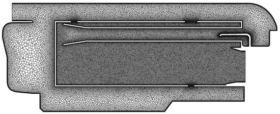
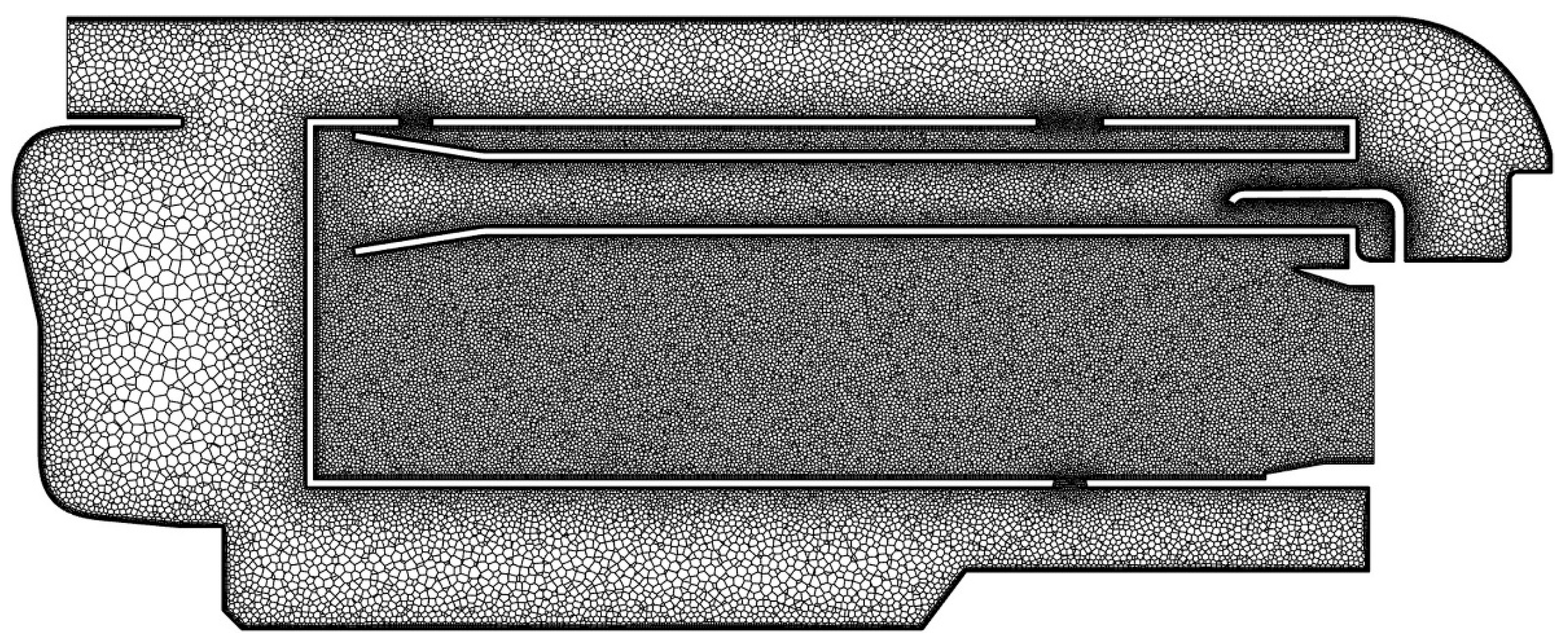
The air inlet surface was assigned a mass flow inlet boundary condition. The combustion chamber outlet was defined by a pressure condition (pressure outlet). Additionally, an average pressure specification option was used, which maintains only the average pressure value at the outlet surface, allowing local pressure variations at individual nodes. Computational meshes were prepared using ANSYS Fluent Meshing software. A key advantage of this software is the ability to use polyhedral elements, which are characterized by good quality reproduction of complex surface shapes. When defining the mesh parameters, particular emphasis was placed on its densification in areas of “increased interest,” i.e., the flow through the evaporator, dilution holes, and the glow tube. A “Scalable Wall Function” model of fluid behavior near the wall was adopted. Due to the significant influence of mesh density on the quality and time of calculations, comparative calculations were performed for three numerical grids of different density (1, 3.5 and 5.2 million meshes), relating the results to the average gas temperature at the outlet of the combustion chamber obtained from tests using Jet-A1 fuel. Calculations using the coarser numerical grid resulted in a temperature increase of several degrees, while calculations using the medium and fine meshes differed by only a few degrees. The likely cause of the overestimation of the temperature for the coarser grid was insufficient modeling of the mixing process, which resulted in the high-temperature zone extending toward the outlet of the glow tube. Given the accuracy of the results and the relatively short computation time (approximately 9 h), a numerical grid with 3.5 million meshes was considered sufficient for further calculations. An example cross-section through the center of a representative section of the combustion chamber computational grid is shown in Figure 5.
Figure 5.
Cross-section through combustor computational grid.
The Reynolds-Averaged-Navier–Stokes (RANS) model with the k −ε Realizable turbulence model was used for turbulent flow calculations. Combustion process simulations were performed using the Steady Diffusion Flamelet of Non-Premixed Combustion Model using the Probability Density Function. The adoption of such a model is justified in the case of large values of the Damkohler number (Da >> 1) [28,29]. In this case, preliminary simulations show that the time scale of turbulent mixing in the main reaction zone is about 10−4 s, while the time scale of the chemical reaction of hydrogen combustion may be about 10−7 s [30]—hence the value of the Damkohler number is of the order of 103, i.e., the condition Da >> 1 is met. Extended chemical kinetic mechanisms were used in the calculations: for hydrogen combustion, the reduced UCSD mechanism with 9 terms and 21 equations [31], and for Jet-A1 combustion, the Z77 framework mechanism with 31 terms and 77 equations [32]. The values of specific heat and enthalpy were determined as functions of temperature for individual mixture components using NASA polynomials, the coefficients of which were determined from thermodynamic databases [33,34].
3. Results and Discussion
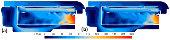
The research was initiated by numerical simulations of the Jet-A1 fuel combustion process in a standard GTM 140 engine combustor for rotational speeds n = 120k rpm and n = 80k rpm, respectively. Analysis of the results indicates that both the static temperature distributions and the flow velocity distributions of the medium inside the chamber are comparable to the results presented in the literature [35]. The average temperature at the outlet of the chamber corresponds to the temperature measured during the authors’ own experimental tests and is approximately 1000 K and 900 K, with an accuracy of a few percent, for the speed n = 120k rpm and n = 80k rpm, respectively. Contour maps of the distribution in the central cross-section (tested chamber section) of static temperature and medium velocity inside the combustion chamber are shown in Figure 6 and Figure 7.
Figure 6.
Contours of the static temperature for the rotational speed: (a) 120k rpm, (b) 80k rpm.
Figure 7.
Contours of velocity magnitude for the rotational speed: (a) 120k rpm, (b) 80k rpm.
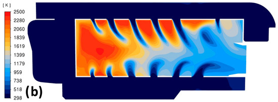
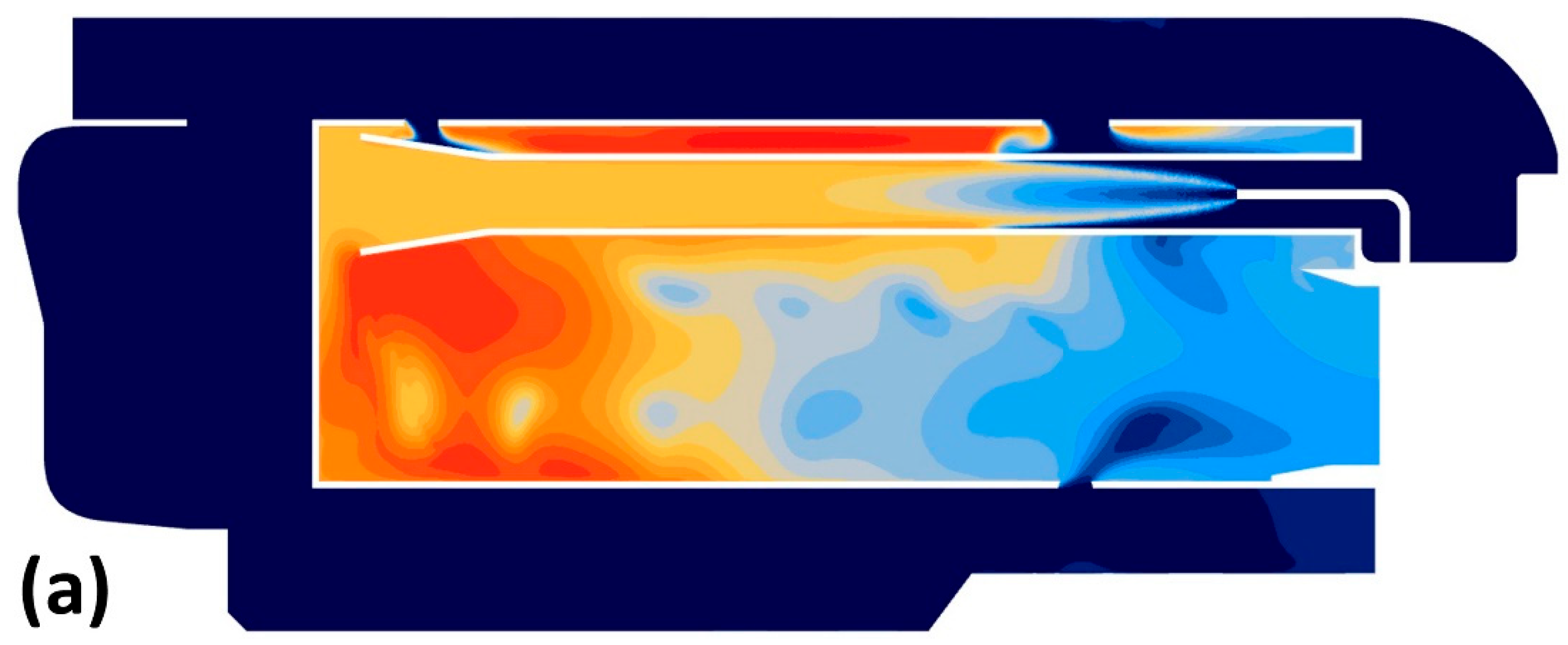
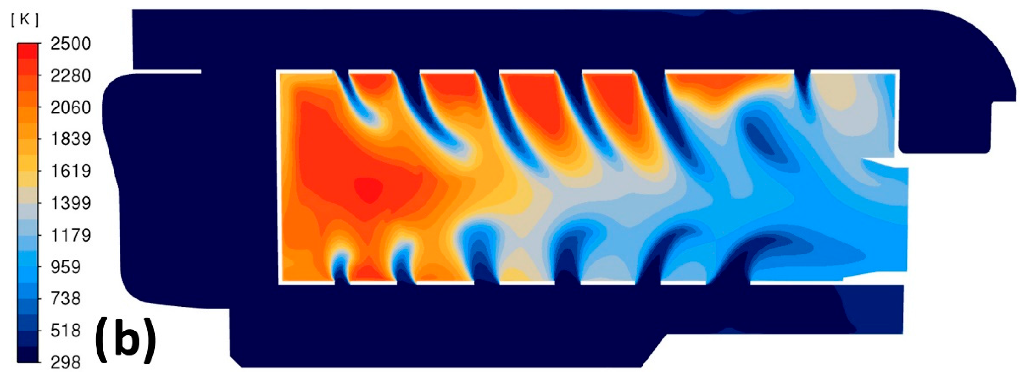
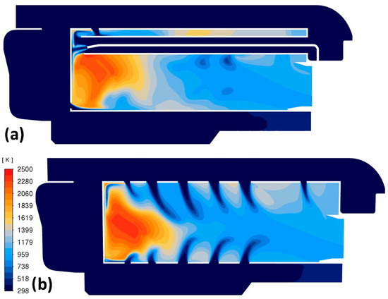
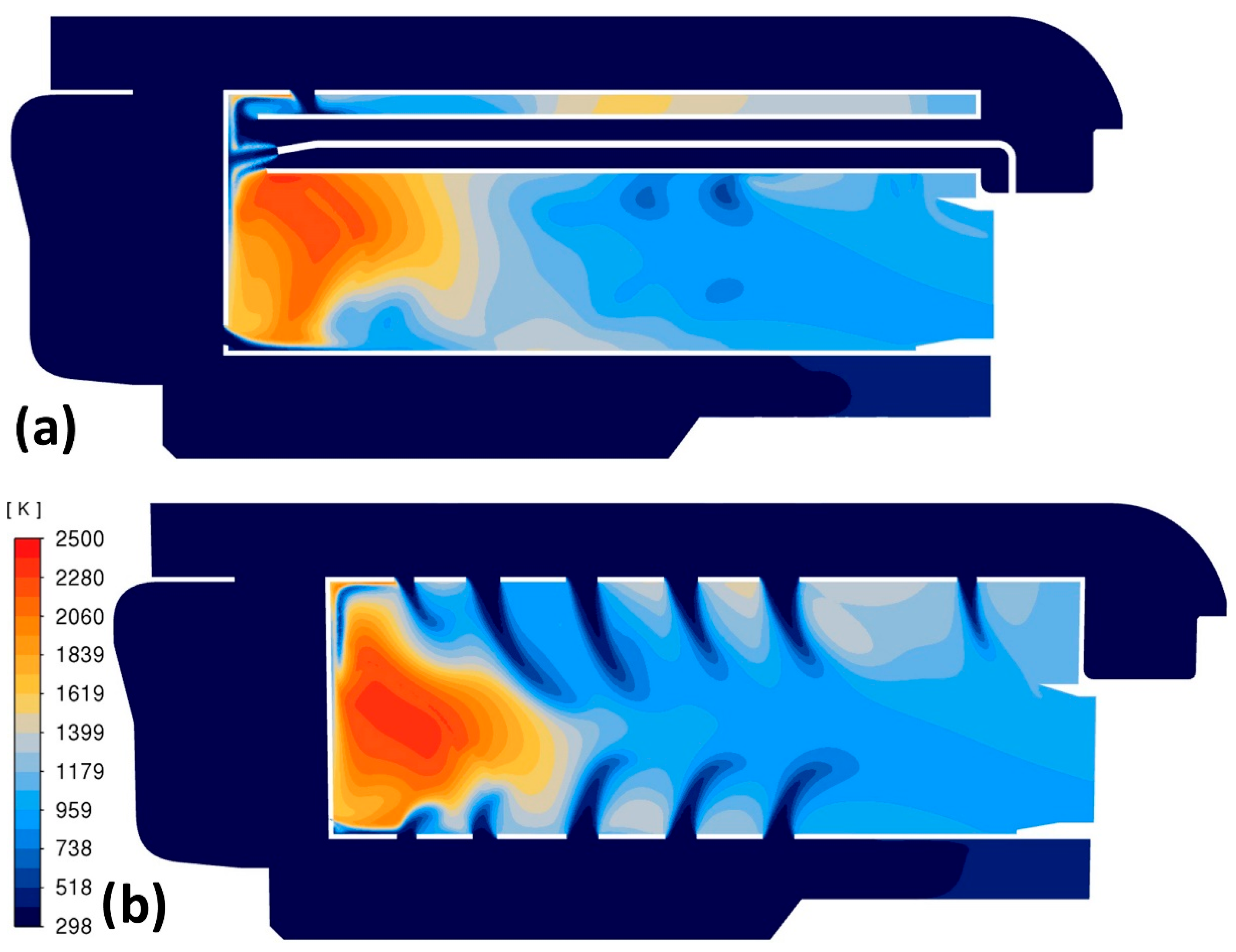
The first numerical simulations using hydrogen as the base fuel were conducted for the standard combustion chamber geometry of the GTM 140 engine. Figure 8a shows the temperature distribution obtained during hydrogen combustion at an engine speed of 120k rpm in the central cross-section of the tested chamber section. Compared to the case of Jet-A1 fuel combustion, the maximum temperature increased by more than 400 K, and a large high-temperature zone can be observed at the side wall of the glow tube, which cannot be diluted by the air streams flowing through the holes in the wall (Figure 8b). Such a high temperature at the wall T > 2000 K could melt the material of the side wall of the glow tube.
Figure 8.
Contours of the static temperature in the central cross-section (a) and in cross-section along the dilution holes (b).
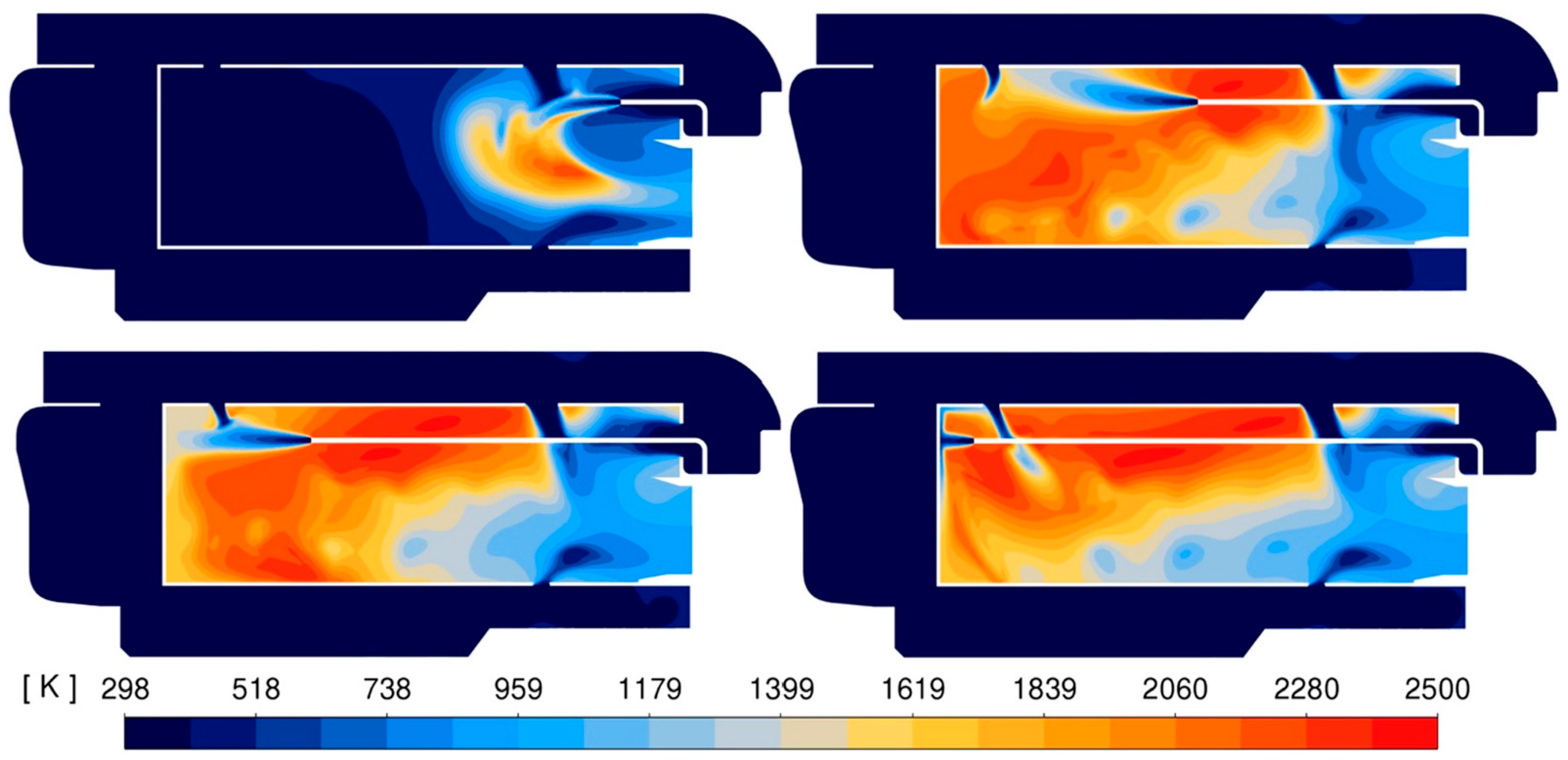
Since the presence of an evaporator tube in a hydrogen-fueled engine appears to be unjustified, simulations of the combustion process without the evaporator were conducted for different hydrogen injection points, varied by simply extending the fuel line. For example, Figure 9 presents the static temperature contours of the combustion process in the central cross-section of the tested area for four different hydrogen injection locations. In all cases, the flame structure was found to be unsatisfactory. For the hydrogen injection location near the chamber outlet, the maximum local temperature at the chamber outlet exceeded the permissible temperature limit for the turbine. In other cases, high-temperature areas form directly at the side walls and front wall of the glow tube. The variants considered indicate that implementing direct hydrogen injection into the combustion chamber in the basic design configuration is problematic. Furthermore, in the tested configurations, the injector and fuel line were located directly in the flame zone, which could lead to their deformation and irregular hydrogen flow. Therefore, the concept of introducing injection into the vaporizer tubes was reconsidered. Its purpose was to protect the fuel line and injector from high temperatures and to supply oxidizer to areas where its quantity is insufficient, ensuring proper organization of the combustion process.
Figure 9.
Comparison of static temperature contours in the central cross-section for different variants of the hydrogen injection location.
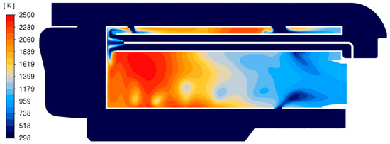
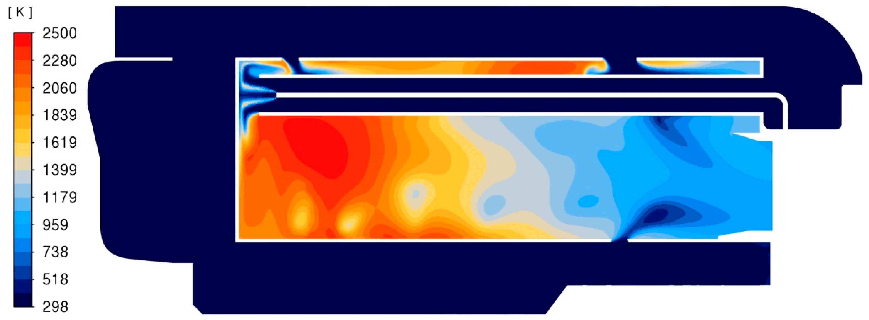
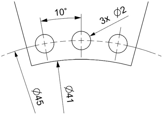
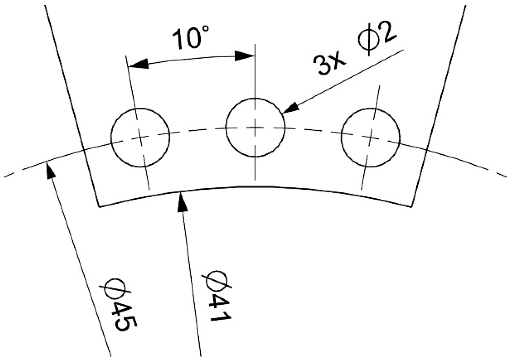
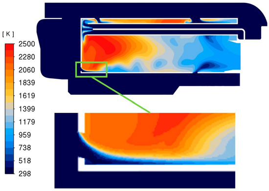
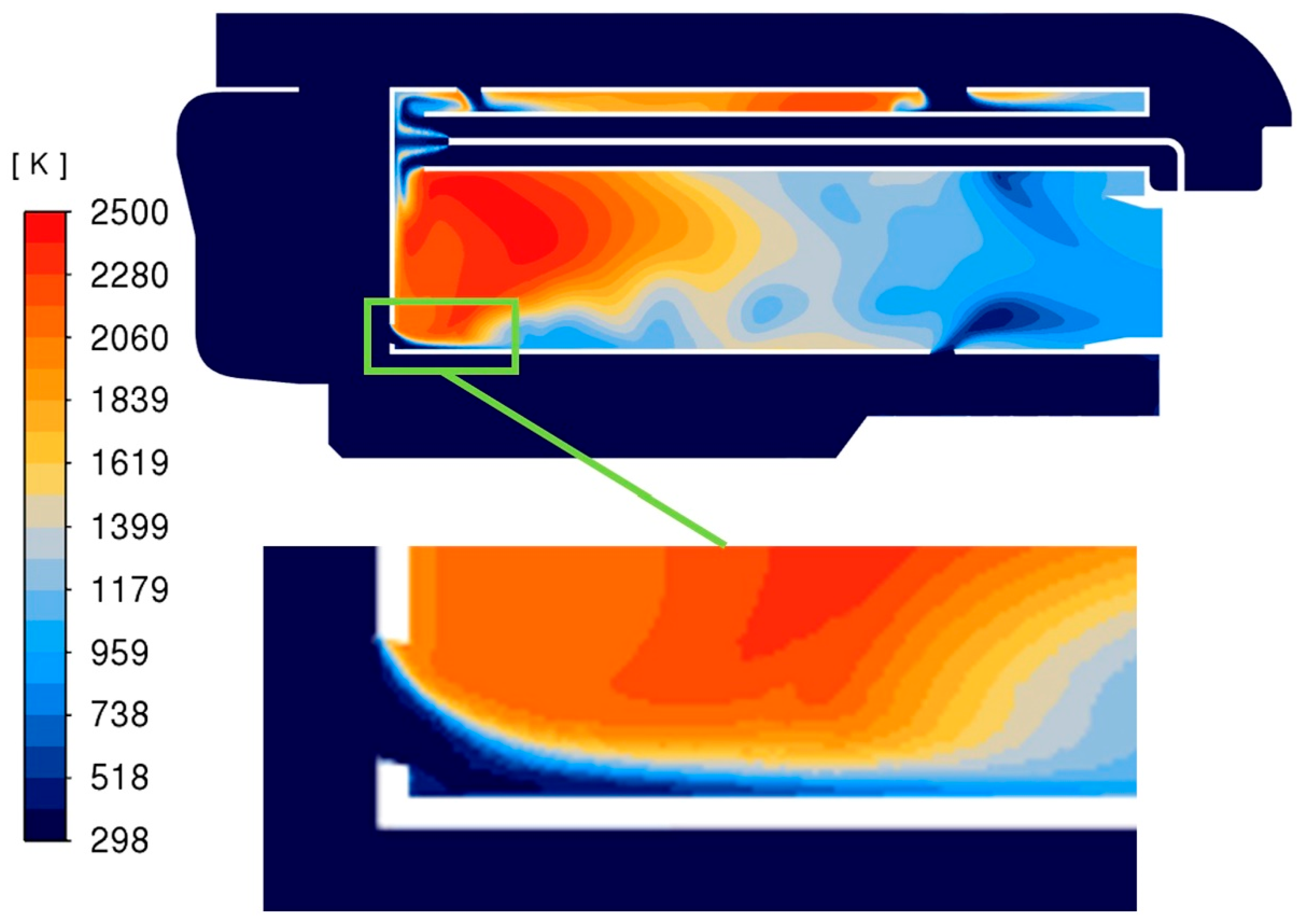
Numerical simulations conducted for various vaporizer tube lengths and hydrogen injection locations indicate that the most favorable combustion process is achieved for vaporizer lengths close to the nominal length and an injection location near the vaporizer outlet. As an example, simulation of this configuration, Figure 10 presents a contour map of the static temperature in the central cross-section for an injection point located 2.5 mm from the end of the evaporator tube. In this case, it was observed that the combustion zone was formed near the front wall of the glow tube. The main goal of this solution was to create a strong airflow that would separate the developing flame from the front wall of the glow tube, preventing the formation of a high-temperature zone on the wall itself. This resulted in a reduction in the maximum temperatures near the wall, T < 2000 K, and a combustion area shape similar to that for Jet-A1 fuel combustion. The temperature, which was still too high, especially near the inner wall of the glow tube, was reduced by introducing additional holes in the front wall of the glow tube, as shown in Figure 11 and Figure 12. This created an airflow that isolated the wall from the flame zone (Figure 13). The consequence of implementing airflow through the additional holes resulted in only minor changes in the flow through all the remaining holes. However, their impact on the hydrogen combustion process proved to be insignificant.
Figure 10.
Static temperature contours in the central cross-section. Hydrogen injection point 2.5 mm upstream of the end of the evaporator tube.
Figure 11.
Schematic diagram of the positions of additional cooling holes for the tested section of the combustion chamber.
Figure 12.
Schematic diagram showing the inclination of additional cooling holes.
Figure 13.
Static temperature contour map on the plane of the central cross-section with air flow providing insulation of the glow tube wall from the combustion zone.
To ensure the proper location of the formation of the hydrogen combustion zone, and above all, to move the hydrogen combustion zone away from the front wall of the glow tube, the research results presented in [36,37] were used to change the air flow rates supplied to the appropriate combustion zones. For this purpose, the last row of the largest dilution holes was covered, which increased the air flow rate supplied to the primary combustion zone at the front of the glow chamber. The combustion process for this case is illustrated using the temperature contour map in Figure 14.
Figure 14.
Static temperature contour map in the plane of the central cross-section for the case with the last row of dilution holes covered.
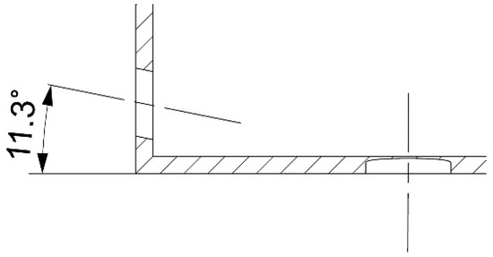
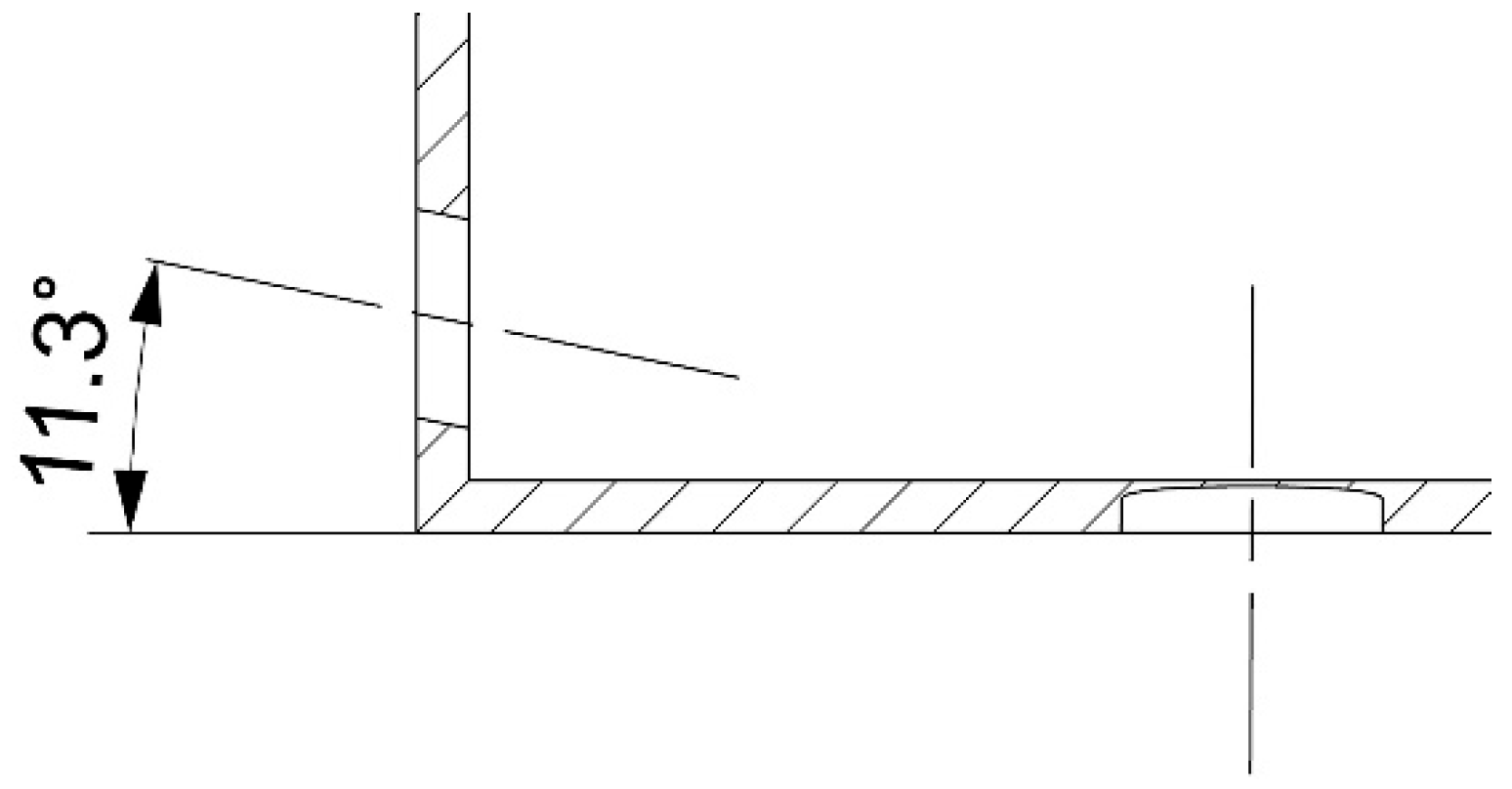
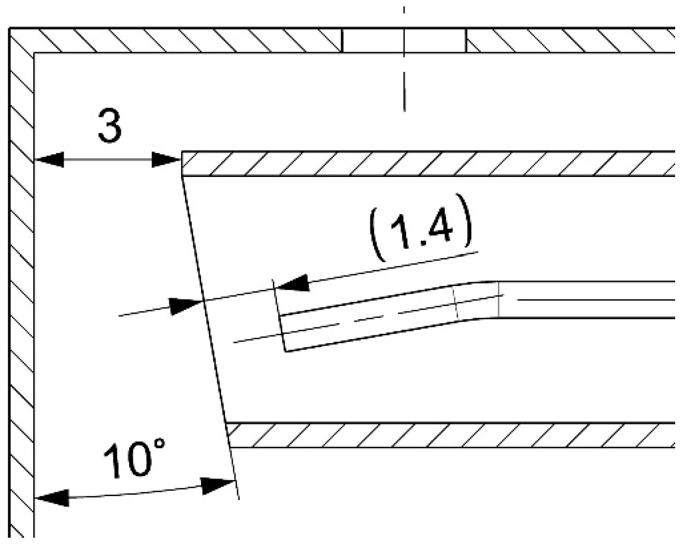
The final design modification involved correcting the geometry of the evaporator outlet and changing the hydrogen injection angle as shown in Figure 15.
Figure 15.
Schematic drawing of the geometric changes introduced in the design of the evaporator and hydrogen outlet nozzle.
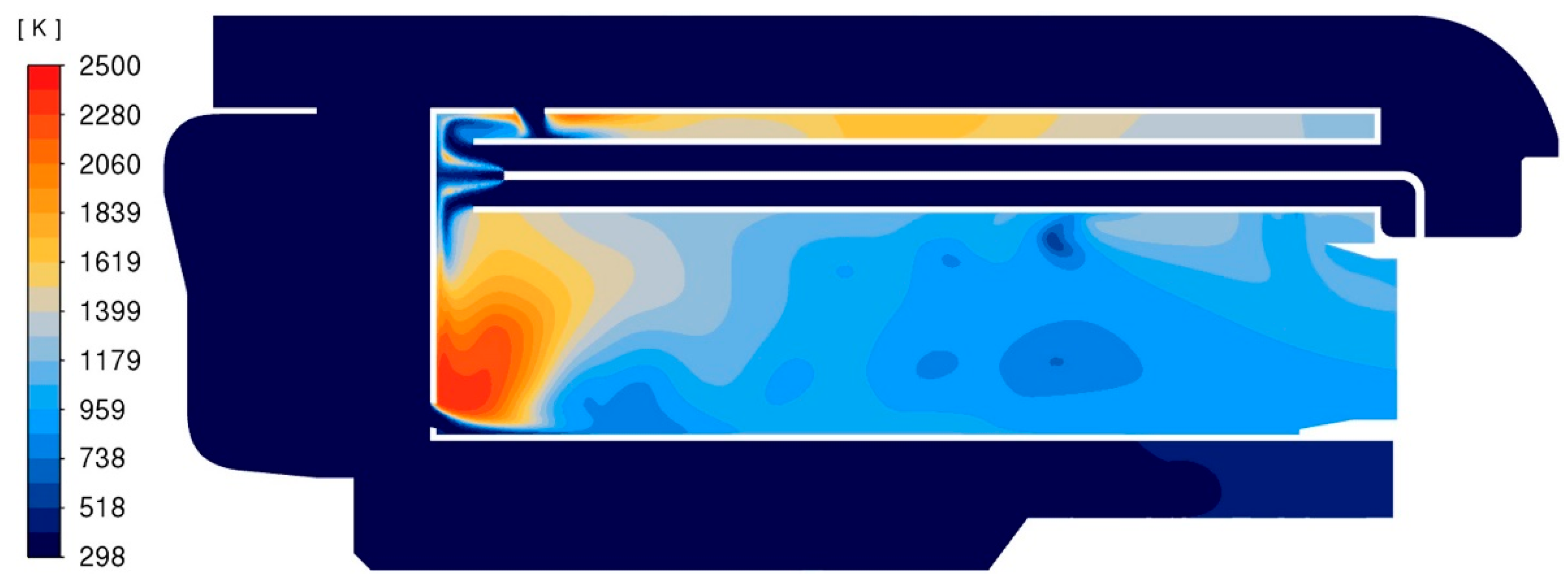
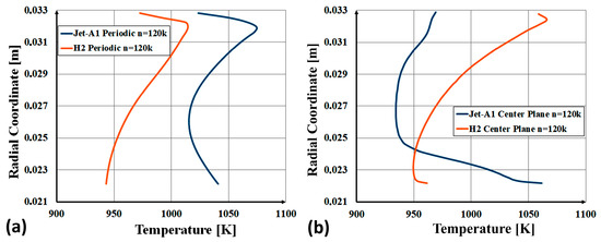
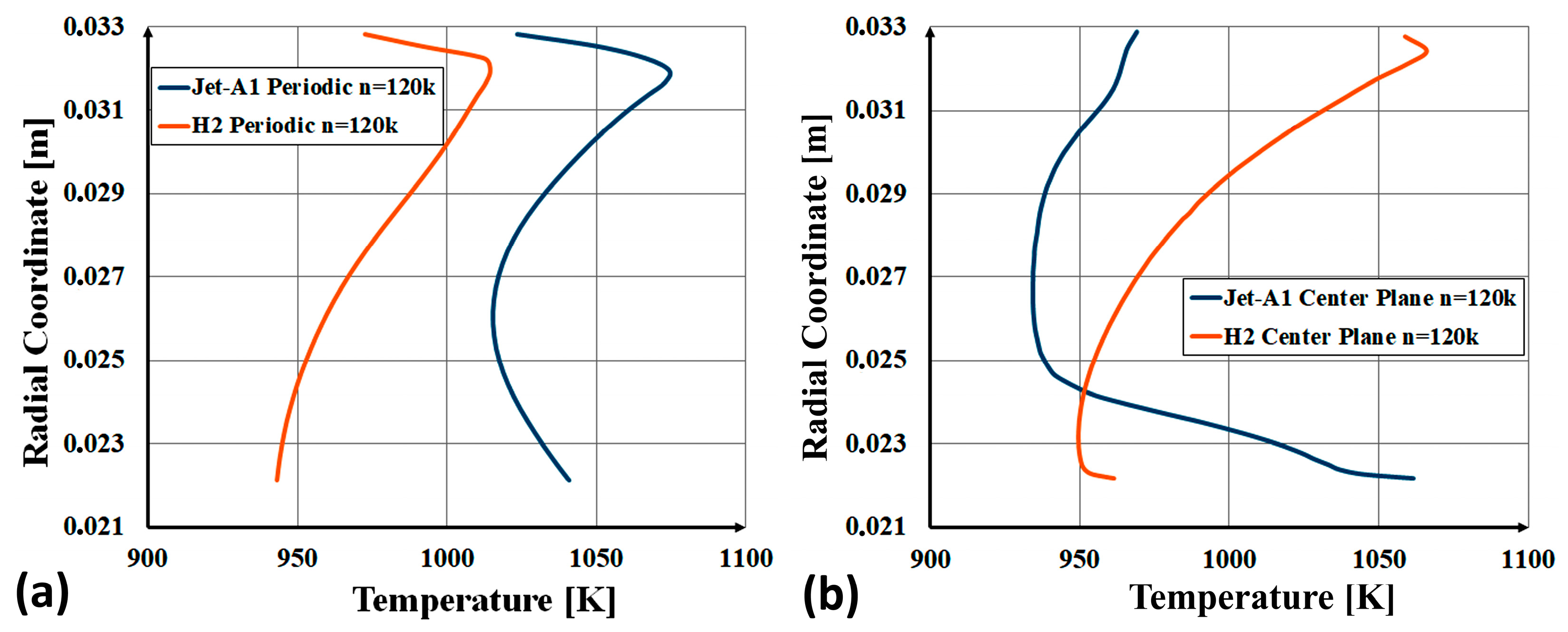
The results of numerical calculations for this configuration are presented in Figure 16a,b. It can be observed that the hydrogen combustion zone is located in the front section of the glow chamber and occupies an area in the central part of the chamber with a relatively uniform temperature without direct contact with the walls of the glow chamber. The averaged static exhaust gas temperature at the combustion chamber outlet is 980 K and is close to the values obtained from numerical simulations and experimental measurements for the combustion of Jet-A1 fuel, which are approximately 990 K. Static temperature distributions in the outlet cross-section of the modernized combustion chamber for hydrogen fuel and in the outlet cross-section of the standard chamber for hydrocarbon fuel are shown in Figure 17. Figure 17a shows the temperature distribution in the periodic plane, while Figure 17b shows the temperature distribution in the central plane. It can be seen that the temperature distribution in the case of hydrogen combustion is comparable for both planes, whereas in the case of hydrocarbon fuel combustion, the distributions differ significantly—in the central plane, a relatively high temperature was obtained at the base of the turbine blade—which may indicate poor air flow through the holes on the inner side of the glow tube. It can be concluded that the introduced design changes created appropriate conditions for stable hydrogen combustion, in particular with regard to the location of the primary combustion zone, while ensuring the thermal safety of the structure.
Figure 16.
Static temperature contour map in the plane of the central cross-section (a) and in the cross-sectional plane of the dilution holes (b) for the case with the last row of dilution holes covered.
Figure 17.
Static temperature distributions in outlet cross-sections of the modernized combustion chamber for hydrogen fuel and the standard combustion chamber for hydrocarbons for the rotational speed of 120k rpm, (a) temperature distribution in the periodic plane, (b) temperature distribution in the central plane.
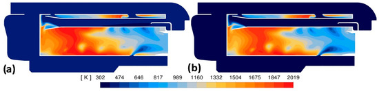
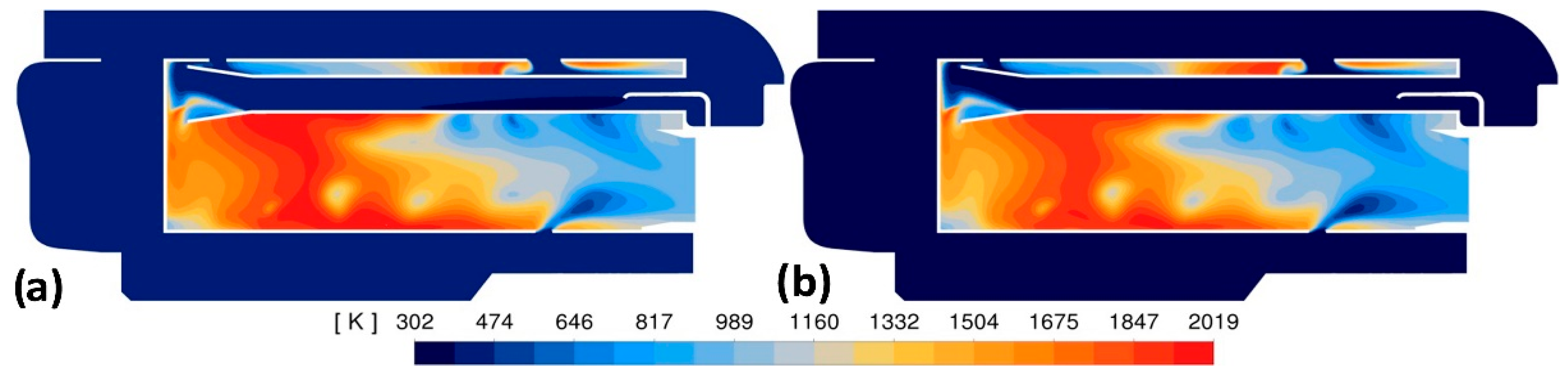
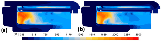
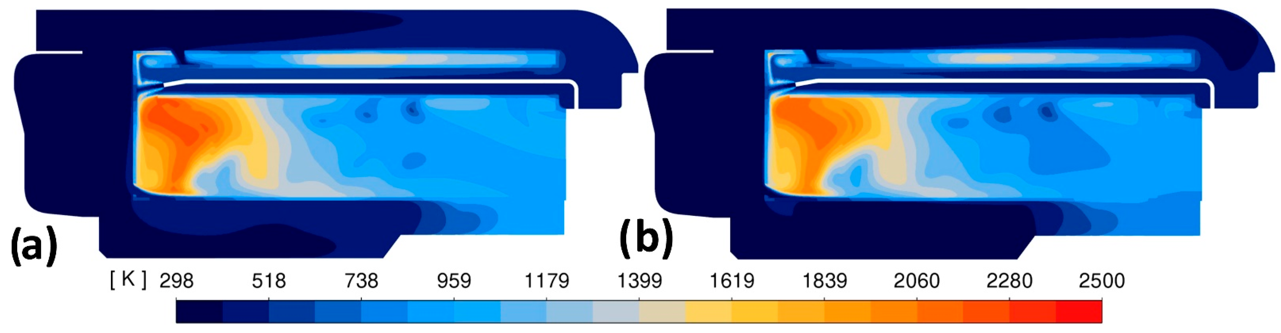
For this final combustion chamber geometry (Figure 16), additional numerical simulations were performed, taking into account heat conduction through the walls of the glow tube and evaporator. Calculations were performed for two rotational speeds: n = 120k rpm and n = 80k rpm (Figure 18). Taking heat conduction through the walls into account, this reduced the maximum combustion process temperatures by approximately 100 K. The static temperature values of the mixture on the walls have also been reduced and are generally within the range of 1100–1320 K. It is worth noting that the high temperature areas within the primary combustion zone for both speeds are very similar in terms of location and shape, which proves the stability of the hydrogen combustion zone for various engine operating points.
Figure 18.
Comparison of static temperature contour maps on the central plane of the cross-section for two rotational speeds: (a) n = 120k rpm and (b) n = 80k rpm.
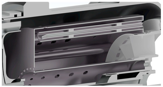
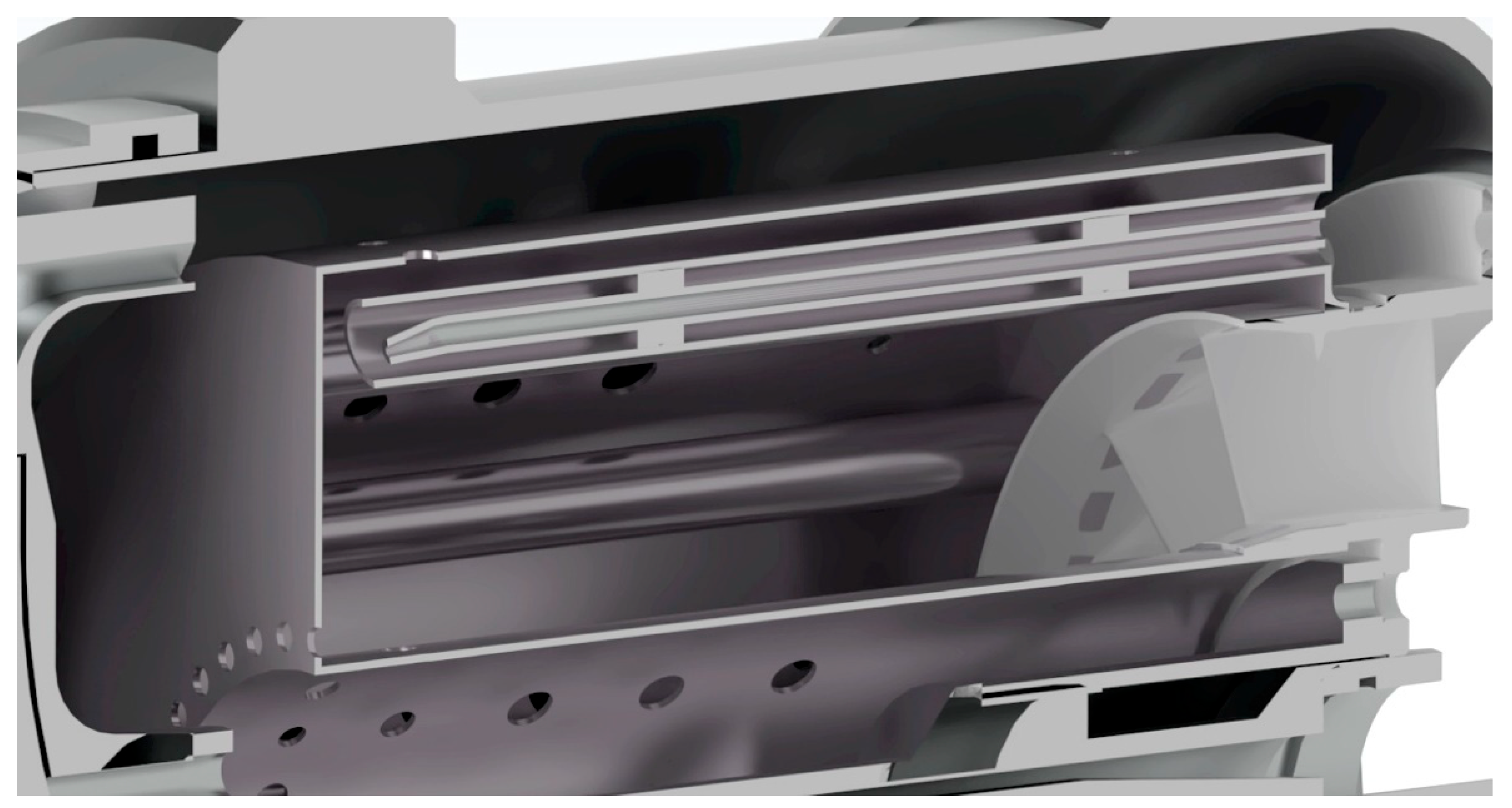
From the energy balance of the combustion chamber of the GTM 140 engine modernized to hydrogen combustion (Figure 19), it can be calculated that the hydrogen combustion efficiency for the nominal rotational speed n = 80k rpm is about 0.986 (a similar efficiency value of about 0.94 was obtained by H. R. Kaufman [16] in experimental studies of hydrogen combustion in the chamber of the J65-B-3 turbojet engine). Detailed experimental studies of a slightly older version of this engine, GTM-120, fueled with Jet-A1 fuel show that for the rotational speed of 80k rpm, the actual combustion efficiency is about 0.86 [4]). The lower combustion efficiency of hydrocarbon fuel may result from several reasons, including the need for fuel evaporation and worse fuel-air mixing conditions. The high hydrogen combustion efficiency obtained on the basis of numerical simulations requires confirmation by experimental tests. It is worth emphasizing that the higher combustion efficiency of hydrogen fuel compared to the combustion efficiency of hydrocarbon fuel may be an important argument in favor of adapting standard MTEs combustion chambers to hydrogen fuel combustion.
Figure 19.
Cross-section visualization of a CAD model of the actual representation of the combustion chamber geometry adapted to the combustion of hydrogen fuel.
4. Conclusions and Summary
The implementation of hydrogen combustion is a key technical challenge in the design and optimization of turbine engine combustors to ensure appropriate efficiency and safety.
This article presents the numerical adaptation of a miniature turbojet engine originally powered by Jet-A1 fuel to a design capable of burning hydrogen fuel. By making relatively simple design changes, which involved selecting the arrangement of holes in the wall of the glow tube to ensure adequate air flow into the glow chamber, as well as by appropriately locating the point and direction of hydrogen injection into the chamber, the flame location and structure were improved—finally, a design of the combustion chamber structure was obtained, in which the hydrogen combustion process should be stable and safe for the thermal resistance of the construction material.
Numerical calculations were performed for two rotational speeds: n = 120,000 rpm and n = 80,000 rpm. In both cases, the high-temperature areas (primary combustion zones) are very similar in location and shape, and the static temperature of the mixture on the walls falls within the acceptable range (for glow tube walls made of high-temperature superalloys) of 1100–1320 K.
It is worth noting that the proposed design changes, that is adapting the standard Jet-A1 fuel-powered chamber to hydrogen fuel combustion, do not entail any fundamental changes to the entire original structure of the chamber and can be implemented in a relatively simple manner.
Numerical simulations of the Jet-A1 fuel combustion process in the tested miniature GTM-140 engine, conducted for comparative purposes, showed high consistency with the results presented in the literature as well as with the results of authors’ experimental studies, which increases the credibility of the analysis of the obtained results. Further numerical and experimental studies are planned to verify the obtained combustor design solutions.
Author Contributions
M.G.: writing—review and editing, conceptualization and methodology; B.M.: investigation, software and visualization. All authors have read and agreed to the published version of the manuscript.
Funding
This research received no external funding.
Data Availability Statement
Data are contained within the article.
Conflicts of Interest
The authors declare no conflicts of interest.
Abbreviations
The following abbreviations are used in this manuscript:
| UAV | Unmanned Aerial Vehicle |
| MTE | Miniature Turbine Engine |
| CFD | Computational Fluid Dynamics |
| CAD | Computer-Aided Design |
| ANSYS | ANalysis SYStems |
| UCSD | University of California, San Diego |
References
- Nex, F.; Armenakis, C.; Cramer, M.; Cucci, D.A.; Gerke, M.; Honkavaara, E.; Kukko, A.; Persello, C.; Skaloud, J. UAV in the Advent of the Twenties: Where We Stand and What Is Next. ISPRS J. Photogramm. Remote Sens. 2022, 184, 215–242. [Google Scholar] [CrossRef] [Scilit]
- González-Jorge, H.; Martínez-Sánchez, J.; Bueno, M.; Arias, P. Unmanned Aerial Systems for Civil Applications: A Review. Drones 2017, 1, 2. [Google Scholar] [CrossRef] [Scilit]
- Zhang, B.; Song, Z.; Zhao, F.; Liu, C. Overview of Propulsion Systems for Unmaned Aerial Vehicles. Energies 2022, 15, 455. [Google Scholar] [CrossRef] [Scilit]
- Gieras, M. Miniaturowe Silniki Turboodrzutowe; Oficyna Wydawnicza Politechniki: Warszawskiej, Poland, 2025; Available online: https://www.researchgate.net/publication/393901226_Miniaturowe_silniki_turboodrzutowe_Miniature_turbojet_engines (accessed on 1 December 2025).
- El-Sayed, A.F. Aircraft Propulsion and Gas Turbine Engines, 2nd ed.; CRC Press: Boca Raton, FL, USA; Taylor & Francis Group: Abingdon, UK, 2017. [Google Scholar]
- Austin, R. Unmanned Aircraft Systems: UAVS Design, Development and Deployment; John Wiley & Sons, Ltd.: Hoboken, NJ, USA, 2010. [Google Scholar] [CrossRef] [Scilit]
- Przysowa, R.; Gawron, B.; Białecki, T.; Łęgowik, A.; Merkisz, J.; Jasiński, R. Performance and Emissions of a Microturbine and Turbofan Powered by Alternative Fuels. Aerospace 2021, 8, 25. [Google Scholar] [CrossRef] [Scilit]
- Erario, M.L.; De Giorgi, M.G.; Przysowa, R. Model-Based Dynamic Performance Simulation of a Microturbine Using Flight Test Data. Aerospace 2022, 9, 60. [Google Scholar] [CrossRef] [Scilit]
- Xiao, T.; He, A.; Pei, X.; Pan, M.; Wang, X.; Hu, Z. Research on Hydrogen-Fuelled Turbojet Engine Control Method Based on Model-Based Design. Processes 2023, 11, 3268. [Google Scholar] [CrossRef] [Scilit]
- Wang, X.; He, A.; Hu, Z. Transient Modelling and Performance Analysis of Hydrogen-Fuelled Aero Engines. Processes 2023, 11, 423. [Google Scholar] [CrossRef] [Scilit]
- Osigwe, E.O. Thermodynamic Performance and Creep Life Assessment Comparing Hydrogen-and Jet-Fuelled Turbofan Aero Engine. Appl. Sci. 2021, 11, 3873. [Google Scholar] [CrossRef] [Scilit]
- Bruno de Vasconcelos Leitão, A.; Bringhenti, C.; Takachi Tomita, J.; Jefferds dos Santos Silva, F.; Xisto, C.; Grönstedt, T. A review of hydrogen aircraft propulsion systems: Recent advances and environmental perspectives. Int. J. Hydrogen Energy 2025, 76, 151489. [Google Scholar] [CrossRef] [Scilit]
- Seyam, S.; Dincer, I.; Agelin-Chaab, M. Novel hybrid aircraft propulsion systems using hydrogen, methane, methanol, ethanol and dimethyl ether as alternative fuels. Energy Convers. Manag. 2021, 238, 114172. [Google Scholar] [CrossRef] [Scilit]
- Ebrahimi, A.; Rolt, A.; Jafari, S.; Huete Anton, J. A review on liquid hydrogen fuel systems in aircraft applications for gas turbine engines. Int. J. Hydrogen Energy 2024, 91, 88–105. [Google Scholar] [CrossRef] [Scilit]
- Heinkel (von Ohain) HeS 3B Turbojet Engine, Reproduction, National Air and Space Museum, 650 Jefferson Drive SW Washington, DC, 202-633-2214. Available online: https://airandspace.si.edu/collection-objects/heinkel-von-ohain-hes-3b-turbojet-engine-reproduction/nasm_A19810039000 (accessed on 24 January 2024).
- Kaufman, H.R. High Altitude Performance Investigation of J65-B-3 Turbojet Engine with Both JP-4 and Gaseous Hydrogen Fuels, Report NACA. 1957. Available online: https://digital.library.unt.edu/ark:/67531/metadc63517/ (accessed on 21 November 2025).
- Goldsmith, J.S.; Bennett, G.W. Hydorgen-Methane Fuel Control Systems for Turbojet Engines, Report NASA. 1973. Available online: https://ntrs.nasa.gov/citations/19740008380 (accessed on 21 November 2025).
- Coïc, C.; Sielemann, M. The Advantages and Challenges of Hydrogen Propulsion, Blog Series, Sustainable Aviation 2023. Available online: https://modelon.com/blog/hydrogen-propulsion-aircraft-advantages-and-challenges/ (accessed on 11 April 2026).
- Gopalasingam, D.; Rakhshani, B.; Rodriguez, C. Hydrogen Propulsion Technologies for Aviation: A Review of Fuel Cell and Direct Combustion Systems Towards Decarbonising Medium-Haul Aircraft. Hydrogen 2025, 6, 92. [Google Scholar] [CrossRef] [Scilit]
- McDonald, C.F.; Massardo, A.F.; Rodgers, C.; Stone, A. Recuperated gas turbine aeroengines. Part III: Engine concepts for reduced emissions, lower fuel consumption, and noise abatement. Aircr. Eng. Aerosp. Technol. Int. J. 2008, 80, 408–426. [Google Scholar] [CrossRef] [Scilit]
- Airbus Deutschland GmbH. Liquid Hydrogen Fuelled Aircraft—System Analysis, Final Technical Report. 2003. Available online: https://www.fzt.haw-hamburg.de/pers/Scholz/dglr/hh/text_2004_02_26_Cryoplane.pdf (accessed on 22 November 2025).
- Sun, X.; Sethi, V.; Singh, G.; Giannouloudis, A.; Rolt, A.; Abbott, D.; Gauthier, P.; Wijesinghe, C. Final Report for the Single Sector H2 Micromix Combustor Segment Performance and NOx Emissions Assessment, ENABLEH2. 2023. Available online: https://ec.europa.eu/research/participants/documents/downloadPublic?documentIds=080166e5f87040de&appId=PPGMS (accessed on 23 November 2025).
- Pratt & Whitney. Alternative Fuel. 2024. Available online: https://www.prattwhitney.com/en/future-of-flight/alternative-fuel (accessed on 23 November 2025).
- General Electric. HYDEA—HYdrogen Demonstrator for Aviation, Project. 2025. Available online: https://www.geaerospace.com/external-funding/hydrogen-demonstrator-for-aviation (accessed on 23 November 2025).
- Rolls-Royce. Rolls-Royce and Easyjet Set New World First. 2022. Available online: https://www.rolls-royce.com/media/press-releases/2022/28-11-2022-rr-and-easyjet-set-new-aviation-world-first-with-successful-hydrogen-engine-run (accessed on 23 November 2025).
- JETPOL. Silniki GTM140. 2025. Available online: https://jetpol.tech/silniki/ (accessed on 27 November 2025).
- Potter, M.C.; Wiggert, D.C.; Ramadan, B.H. Mechanics of Fluids, 5th ed.; SI Version; Cengage Learning: Boston, MA, USA, 2012. [Google Scholar]
- Peters, N. Turbulent Combustion; Cambridge University Press: Cambridge, UK, 2000; Available online: https://ebookcentral-1proquest-1com-1ki5zuitw00c9.eczyt.bg.pw.edu.pl/lib/wtu/reader.action?docID=202243&c=UERG&ppg=1 (accessed on 27 April 2026).
- Pitsch, H.; Peters, N. A Consistent Flamelet Formulation for Non-Premixed Combustion Considering Differential Diffusion Effects. Combust. Flame 1998, 114, 26–40. [Google Scholar] [CrossRef] [Scilit]
- Sánchez, A.L.; Liñán, A.; Williams, F.A.; Balakrishnan, G. Theory of Structures of Hydrogen-Air Diffusion Flames. Combust. Sci. Technol. 1995, 110, 277–301. [Google Scholar] [CrossRef] [Scilit]
- CERFACS, Hydrogen/Air Combustion Mechanisms (Cantera). 2025. Available online: https://www.cerfacs.fr/cantera/mechanisms/hydro.php (accessed on 24 December 2025).
- Zettervall, N.; Fureby, C.; Nilsson, E. A reduced chemical kinetic reaction mechanism for kerosene-air combustion. Fuel 2020, 269, 117446. [Google Scholar] [CrossRef] [Scilit]
- Kee, R.J.; Rupley, F.M.; Miler, J.A. The Chemkin Thermodynamic Data Base, Sandia National. Laboratories Report SAND87-8215B. 1990. Available online: https://ui.adsabs.harvard.edu/abs/1990ctdb.rept.....K/abstract (accessed on 24 December 2025).
- Burcat, A.; Ruscic, B. Third Millennium Ideal Gas and Condensed Phase Thermochemical Database for Combustion with Updates from Active Thermochemical Tables. 2005. Available online: https://www.academia.edu/26277336/ (accessed on 27 December 2025).
- Suchocki, T.; Lampart, P.; Klonowicz, P. Numerical investigation of a GTM-140 turbojet engine. Open Eng. 2015, 5, 478–484. [Google Scholar] [CrossRef] [Scilit]
- Chmielewski, M. Badanie Wpływu Zmiennej Geometrii Komory Spalania na Efektywność Procesów Spalania i Emisję Substancji Szkodliwych w Miniaturowej Turbinie Gazowej. Doctoral Thesis, Warsaw University of Technology, Warsaw, Poland, 2016. Supervisor M. Gieras. Available online: https://www.meil.pw.edu.pl/eng/MEiL/Studia/Studia-doktoranckie/Nadane-doktoraty/Maciej-Chmielewski (accessed on 15 January 2026).
- Chmielewski, M.; Gieras, M. Impact of variable geometry combustor on performance and emissions from miniature gas turbine engine. J. Energy Inst. 2017, 90, 257–264. [Google Scholar] [CrossRef] [Scilit]

Disclaimer/Publisher’s Note: The statements, opinions and data contained in all publications are solely those of the individual author(s) and contributor(s) and not of MDPI and/or the editor(s). MDPI and/or the editor(s) disclaim responsibility for any injury to people or property resulting from any ideas, methods, instructions or products referred to in the content. |
© 2026 by the authors. Licensee MDPI, Basel, Switzerland. This article is an open access article distributed under the terms and conditions of the Creative Commons Attribution (CC BY) license.