


Abstract
Hydrogen transport under high-pressure conditions poses significant challenges for pipeline materials and structural design. Existing studies on PA12-based systems are primarily limited to material-level characterization, with insufficient validation at the pipeline scale. To address this gap, this study presents the design and system-level experimental validation of an all-thermoplastic composite hydrogen pipeline. A full-scale DN50 pipeline, consisting of a PA12 liner and a ±54° filament-wound carbon fiber-reinforced layer, was fabricated and tested under hydrogen pressures up to 10 MPa, including long-term exposure and cyclic loading. The results indicate stable deformation behavior and low hydrogen permeation (~10−14 mol·m/(m2·s·Pa)) within the investigated pressure range, with a burst pressure exceeding 60 MPa. A transition from stable to accelerated deformation was identified at elevated pressure, indicating a structural operating limit. Post-test observations reveal that interlaminar damage, rather than primary interface failure, governs long-term degradation. Based on these findings, a design framework integrating stress-based, deformation-based, and damage-based criteria is proposed. This work extends PA12-based hydrogen pipeline research from material-level understanding to system-level validation and provides practical guidance for structural design and performance evaluation.
1. Introduction
Hydrogen is widely regarded as a cornerstone energy carrier for enabling deep decarbonization in hard-to-abate sectors such as heavy industry, long-distance transportation, and seasonal energy storage [1,2,3]. With the rapid expansion of renewable-powered hydrogen production, the development of safe, cost-effective, and scalable hydrogen transportation infrastructure has become a critical enabler. Among the existing transport options, pipelines remain the most efficient solution for long distance, large-capacity delivery [4,5,6]. However, compared with conventional natural gas systems, hydrogen pipeline deployment faces substantial material and structural challenges.
A primary concern in metallic hydrogen pipelines is hydrogen embrittlement, which can induce crack initiation, accelerate fatigue growth under cyclic pressure loading, and ultimately lead to premature failure [7,8,9]. The small molecular size and high diffusivity of hydrogen further exacerbate permeation, leakage, and integrity risks, particularly under high-pressure conditions [10]. These issues significantly constrain material selection, increase inspection frequency, and raise the life cycle costs. Moreover, metallic pipelines operating in buried or offshore environments require complex corrosion protection systems and cathodic protection, adding further operational and maintenance complexity [11,12].
Against this backdrop, non-metallic and thermoplastic composite pipelines have attracted increasing attention as promising alternatives [13,14,15]. Polymer liners inherently avoid classical hydrogen embrittlement mechanisms, while fiber-reinforced layers provide the necessary load-bearing capacity [16,17,18]. Multilayer composite configurations, integrating polymer liners, reinforcement layers, and protective outer jackets, offer advantages such as corrosion resistance, flexible installation through spooling, and reduced welding requirements [19,20]. Such systems can significantly simplify hydrogen pipeline construction and enhance economic competitiveness, particularly in distributed or geographically complex deployment scenarios.
Recent studies have increasingly focused on understanding hydrogen–polymer interactions from both macroscopic and microscopic perspectives, providing critical insights for hydrogen transport applications. Exposure to high-pressure hydrogen can induce damage evolution, swelling, and plasticization in polymers, which may compromise their mechanical integrity and barrier performance [1,21]. Molecular simulations and in situ experiments have further revealed that hydrogen permeability is strongly influenced by polymer microstructure, including crystallinity, free volume, and chain mobility, resulting in material-specific transport behaviors [22]. In particular, polyamide-based materials indicate superior hydrogen barrier performance due to dense molecular packing and strong intermolecular interactions [23], whereas polyethylene exhibits complex responses under high-pressure conditions, including pressure-induced structural changes and decompression effects [24,25,26]. Additionally, recent advances in thin-ply thermoplastic composites highlight that hydrogen transport is not solely a material property but is also affected by composite architecture and fiber–matrix interactions [27]. Reviews of polymeric materials in high-pressure hydrogen environments emphasize the limitations of existing materials and the need for im supported design strategies to ensure safe and reasonably stable operation [28,29].
However, existing studies on PA12-based hydrogen pipelines are predominantly limited to material characterization or small-scale composite specimens, providing limited insight into structural design and system-level performance under realistic service conditions. In particular, the interaction between deformation and hydrogen permeation at the pipeline scale remains unclear, and a design approach linking structural parameters to overall performance is still lacking [30,31].
To address these gaps, this study presents the design and full-scale experimental validation of an all-thermoplastic composite hydrogen pipeline. A DN50 multilayer pipeline was fabricated and tested under high-pressure hydrogen conditions up to 10 MPa. By combining deformation measurement with permeation analysis, the coupled structural–transport behavior is evaluated at the system level. The results provide a design-oriented understanding of how structural configuration influences performance and establish an approach for linking material selection, structural design, and operational limits in composite hydrogen pipelines.
2. Pipeline Structural Design and Fabrication
2.1. Structural Design of Composite Hydrogen Pipelines
To meet the requirements of high-pressure hydrogen transport in marine environments, a thermoplastic composite pipeline was designed with a target operating pressure of 10 MPa. Under such conditions, the pipeline must simultaneously satisfy pressure-bearing capacity, hydrogen barrier performance, and long-term service stability.
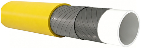
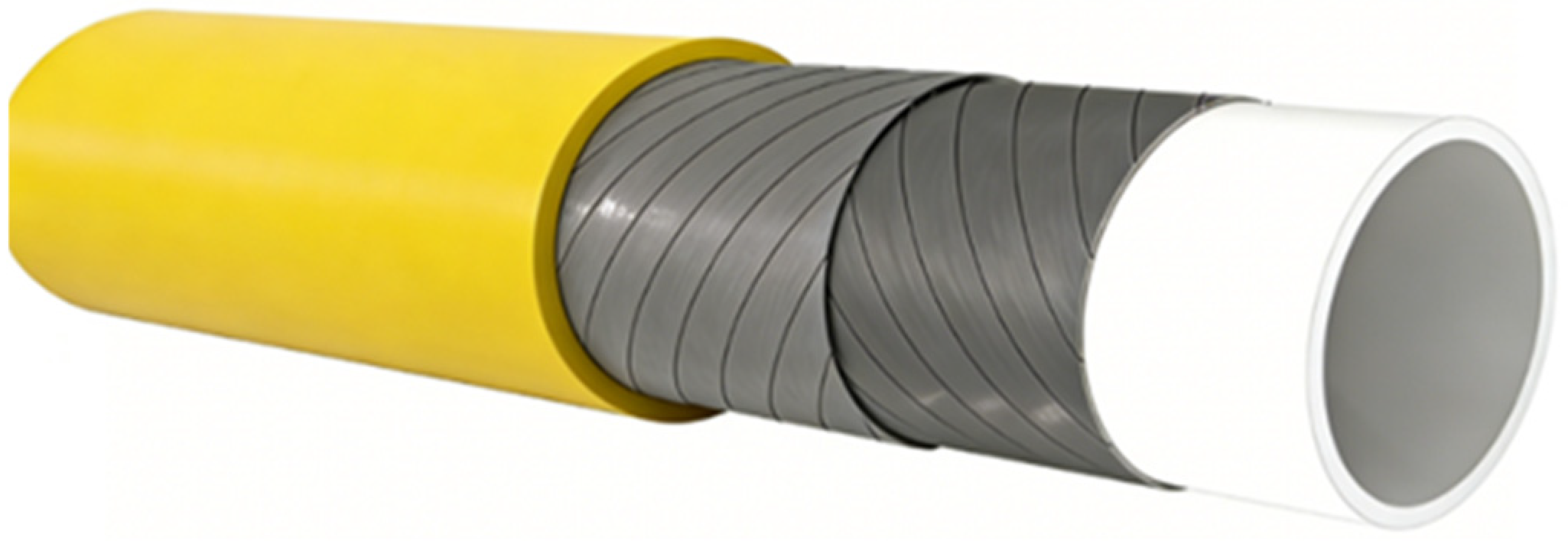
The designed pipeline adopts a typical three-layer architecture, consisting—from the inside outward—of an inner liner, a fiber-reinforced load-bearing layer, and a protective layer, as illustrated in Figure 1. The inner liner is fabricated from polyamide 12 (PA12), selected for its excellent hydrogen barrier properties and strong resistance to environmental stress cracking. Previous studies have reported that the hydrogen permeability coefficient of PA12 at ambient conditions is on the order of 10−14 mol·m/(m2·s·Pa), significantly lower than that of conventional polyethylene-based pipeline materials, thereby effectively mitigating hydrogen leakage. In addition, PA12 exhibits superior resistance to rapid gas decompression-induced blistering, making it suitable for high-pressure gas transport applications.
Figure 1.
Structural diagram of the thermoplastic composite hydrogen pipeline.
For clarity, the key parameters used in the structural design are defined as follows: is the internal pressure, is the mean diameter of the pipeline, is the effective thickness of the load-bearing reinforcement layer, and represent the hoop and axial stresses of the pipeline, respectively, is the tensile strength of the fiber, is the fiber volume fraction, is the winding angle, and is the safety factor.
From a structural mechanics perspective, the pipeline can be approximated as a thin-walled cylindrical structure subjected to internal pressure. The corresponding hoop stress and axial stress can be expressed as:
It can be seen that the hoop stress is approximately twice the axial stress. In fiber-reinforced composites, fibers primarily carry loads along their axial direction; therefore, the winding angle must ensure a balanced load-bearing contribution in both hoop and axial directions. According to classical netting theory, the load-bearing capacity of fibers in different directions is proportional to sin2θ and cos2θ, respectively. By establishing the equilibrium between applied stresses and fiber load-bearing capacity, the following relationship is obtained:
This yields an optimal winding angle of θ ≈ 54.7°, which contributes to mechanical balance and prevents torsional instability.
Regarding the stacking design, the reinforcement layer employs carbon fiber prepreg tapes with a thickness of 0.3 mm. A symmetric four-layer cross-winding sequence (clockwise and counterclockwise alternation) is adopted, followed by multi-layer stacking. Based on the target operating pressure (10 MPa) and geometric dimensions, the number of layers is determined to ensure that the equivalent hoop load-bearing capacity exceeds the hoop stress induced by internal pressure with an appropriate safety margin. In practice, the load-bearing capacity can be further enhanced by increasing the number of layers or the fiber volume fraction. In this study, a multi-layer symmetric layup strategy was employed to balance structural strength and stability while maintaining manufacturability.
Based on the above stress framework, the structural design must further ensure that the load-bearing capacity of the reinforcement layer exceeds the stress induced by internal pressure. For this purpose, a design criterion is introduced by comparing the macroscopic hoop stress with the effective load-bearing capacity of the fiber reinforcement. The hoop stress induced by internal pressure is shown as Equation (1). The effective load-bearing capacity of the reinforcement layer in the hoop direction can be approximated as:
To ensure structural safety, the following condition must be satisfied:
where the safety factor SFSFSF is introduced to account for uncertainties such as manufacturing defects, interfacial imperfections, and long-term degradation under hydrogen exposure. In this study, was adopted as a conservative design range.
Based on the target operating pressure (10 MPa) and pipeline dimensions, the reinforcement thickness ttt and the number of layers are determined by satisfying the above inequality. A symmetric multilayer stacking sequence was employed using carbon fiber/PA12 prepreg tapes with a single-layer thickness of 0.3 mm. An eight-layer ±54.7° cross-winding configuration was selected to ensure that the load-bearing capacity exceeds the applied stress with sufficient safety margin while maintaining manufacturability and structural stability.
It should be noted that the liner and outer protective layers are not treated as primary load-bearing components in this design approach. However, they contribute to the overall structural integrity, environmental resistance, and hydrogen barrier performance. Due to the absence of established design standards for thermoplastic composite hydrogen pipelines, the present approach is derived from classical composite pressure vessel theory and adapted for pipeline applications.
2.2. Fabrication Process of Composite Pipelines
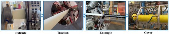
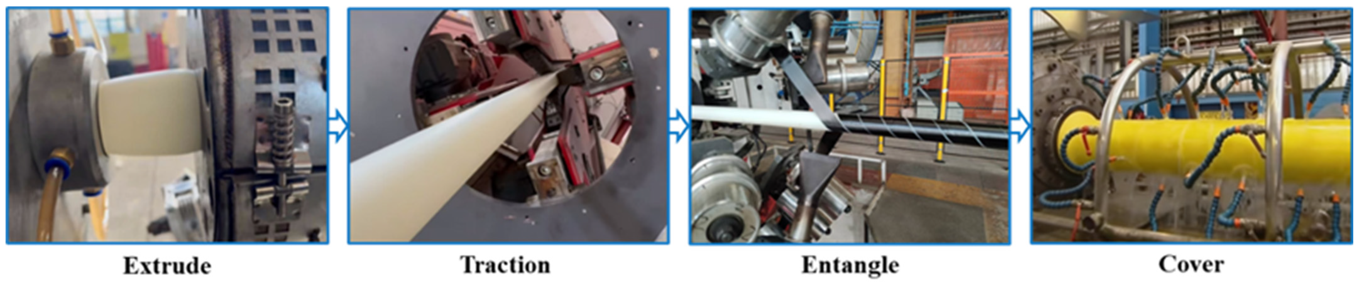
Based on the above structural design, the composite hydrogen pipeline was fabricated through a sequential process including inner liner extrusion, filament winding, and outer layer over-extrusion, as illustrated in Figure 2. To ensure manufacturing consistency and structural reliability, key processing parameters were strictly controlled throughout each stage.
Figure 2.
Composite pipeline preparation process flowchart.
First, the PA12 inner liner was produced using a single-screw extrusion process. The raw PA12 pellets were pre-dried prior to processing to eliminate moisture and reduce the risk of void formation. During extrusion, the temperature across different heating zones was maintained within 200–220 °C, and the screw speed was kept stable to ensure uniform melt plasticization. The dimensional stability of the liner was controlled through die calibration and continuous monitoring, resulting in an outer diameter of 50–55 mm and a wall thickness of approximately 3–5 mm for the DN50 pipe. This provides a consistent and uniform substrate for subsequent reinforcement.
Subsequently, the prepared liner was used as a mandrel for filament winding of thermoplastic prepreg tapes. The prepreg tapes, consisting of carbon fibers pre-impregnated with a PA12 matrix, were wound under controlled tension to ensure uniform fiber distribution and reduce structural variability. The winding angle was fixed at ±54.7°, and an alternating multi-layer stacking sequence was adopted to construct a symmetric eight-layer reinforcement structure. During winding, in situ heating was applied to maintain the matrix temperature above the melting point of PA12, ensuring sufficient resin flow and promoting interfacial fusion between layers. At the same time, compaction rollers were applied continuously to consolidate the deposited layers, enhance interlayer contact, and minimize void content within the composite structure.
Finally, an outer PA12 protective layer was applied through a secondary extrusion coating process. Molten PA12 was uniformly deposited onto the reinforcement layer, forming a continuous and dense outer shell. This layer serves as both environmental protection and as an additional constraint to maintain the integrity of the multilayer structure.
Through the combined control of material pre-treatment, processing temperature, winding tension, and in situ compaction, the fabrication process contributes to a high degree of reproducibility and structural consistency. These measures are critical for minimizing defects, ensuring reasonably stable interfacial bonding, and providing a stable basis for subsequent mechanical and permeation evaluation.
The resulting composite pipeline exhibits an integral multilayer structure consisting of a continuous sealing liner, a load-bearing reinforcement layer, and a protective outer layer. The detailed structural parameters are summarized in Table 1.
Table 1.
Structural parameters of PA12 composite hydrogen pipeline.
3. Experimental Validation Under High-Pressure Hydrogen Environment
3.1. High-Pressure Hydrogen Testing System
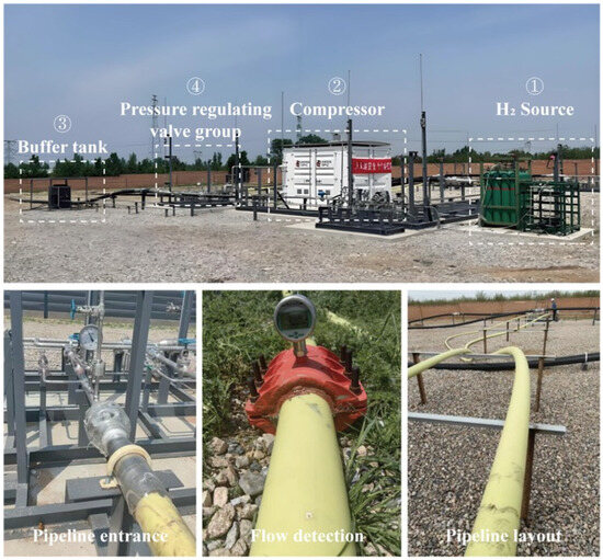
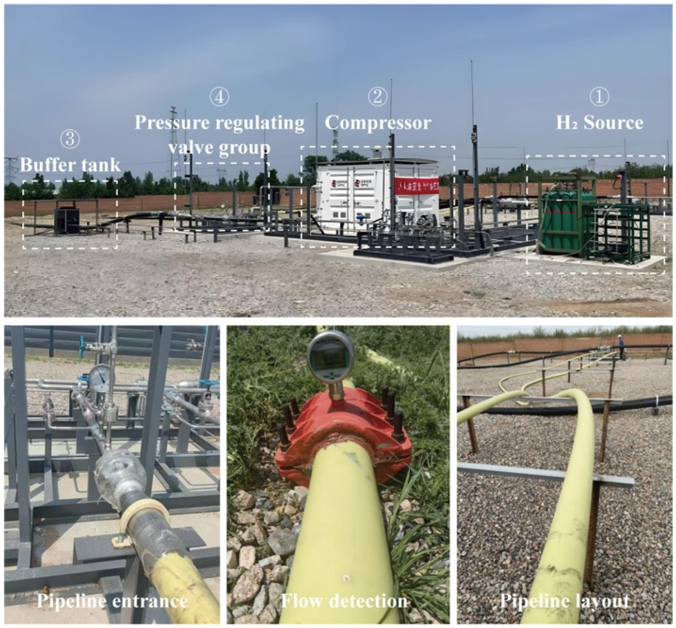
To validate the performance of the designed pipeline under realistic service conditions, high-pressure hydrogen testing was conducted at the Central Research Institute of State Power Investment Corporation, China. The testing platform is capable of long-duration operation under high-pressure, high-purity hydrogen environments. Due to safety requirements for high-pressure hydrogen testing, the experiments were conducted in an open-field environment. Pressure is the primary controlled variable, so in order to reduce the influence of environmental variation, data at each pressure level were selected and analyzed over relatively stable time intervals. Therefore, the observed trends should be interpreted as pressure-dominated responses under coupled environmental conditions.
As shown in Figure 3, the system mainly consists of a high-pressure hydrogen supply module, compression and pressurization unit, buffer storage tank, precision pressure regulation and control valves, and an online monitoring system. It enables continuous operation under ultra-high-purity hydrogen conditions (purity > 99.999%), with precise pressure control, real-time leakage monitoring, and safety interlock protection.
Figure 3.
Pipeline layout at the high-pressure hydrogen test site.
The key parameters in this study include pressure, hydrogen concentration, and pipeline diameter. According to the test requirements, the system is equipped with a high-precision sensing unit.
Pressure monitoring: Arrange absolute pressure transmitters with a range of 12 MPa at the inlet, outlet, and buffer tank of the test pipe section. The test accuracy is ±0.05% of fullscale (FS). During operation, pressure fluctuations were continuously recorded and maintained within a narrow range to ensure stable boundary conditions.
Hydrogen leak detection: Use an inhalation hydrogen detector to detect leaks in pipelines. The detector has online monitoring and recording functions, and the detection sensitivity is 0.1 ppm. This level of sensitivity enables reasonably stable identification of low-level hydrogen leakage under high-pressure conditions.
Diameter measurement: The pipeline diameter was measured using a laser-based displacement measurement system with a resolution of 0.01 mm and an overall measurement accuracy of ±0.02 mm. Considering that the maximum observed diameter change is on the order of 1–2 mm, the relative measurement error remains below 2%, which is acceptable for engineering evaluation.
3.2. Structural Stability Analysis of the Pipeline
A full-scale DN50 composite pipeline was subjected to a stepwise pressurization and long-term operation test, with structural parameters summarized in Table 2. The testing protocol was designed as follows: the system pressure was first increased to 4 MPa and maintained for 21 days, followed by sequential increases to 6 MPa and 8 MPa, each held for 21 days. Finally, the pressure was raised to 10 MPa and sustained for 14 days, resulting in a total duration of 77 days.
Table 2.
Ladder boost operation conditions.
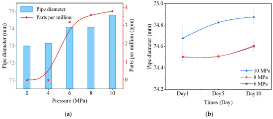
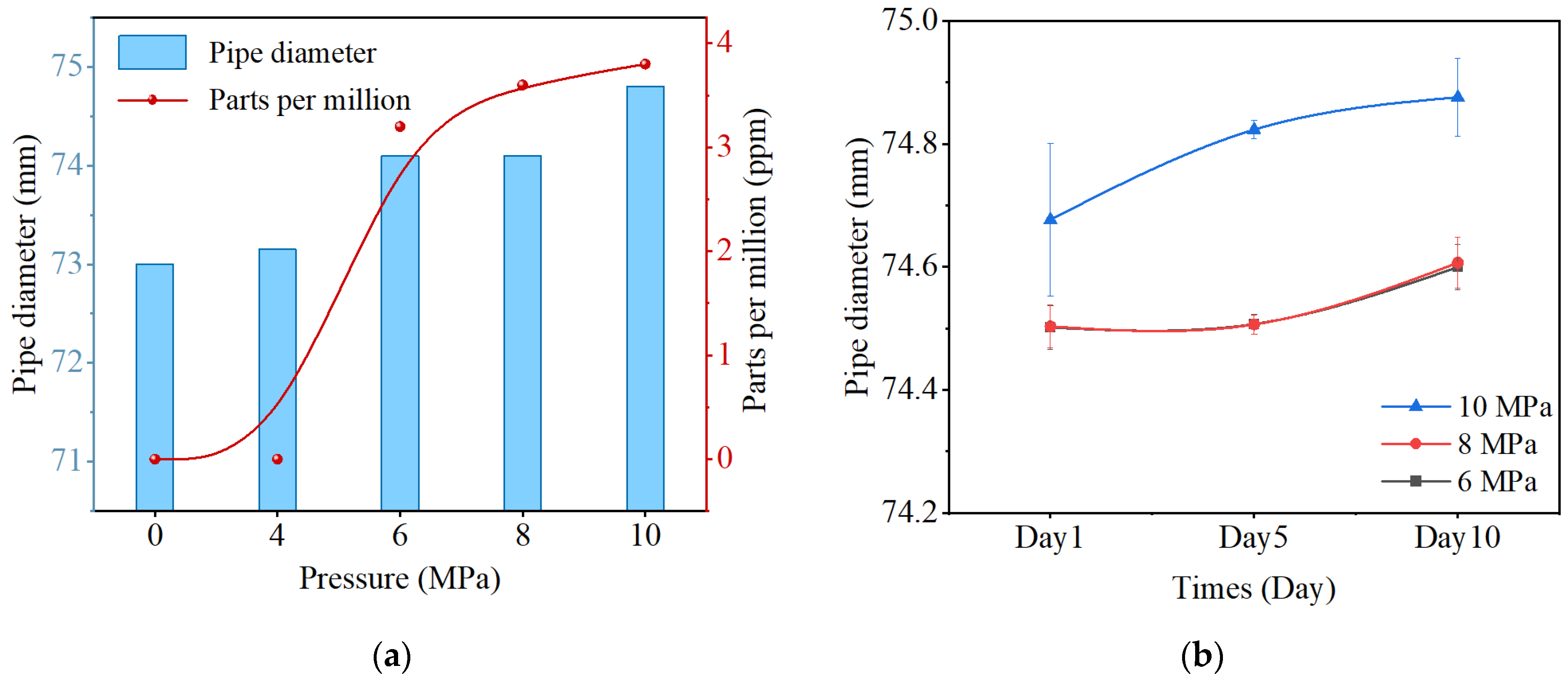
Throughout each pressure stage, pressure fluctuations remained within the prescribed range, with no evidence of sustained pressure decay or abnormal instability. The experimental results (Figure 4) present the evolution of pipeline diameter and ambient hydrogen concentration over the entire test period.
Figure 4.
Test results of hydrogen pipelines under different pressures. (a) Changes in pipe diameter and ambient hydrogen concentration under different pressure conditions. (b) Changes in pipe diameter with working time.
As shown in Figure 4a, leakage monitoring results indicate that no detectable hydrogen leakage (0 ppm) occurred at 4 MPa. At higher pressures, low but measurable hydrogen concentrations of 3.2 ppm, 3.8 ppm, and 4.0 ppm were recorded at 6 MPa, 8 MPa, and 10 MPa, respectively. Although a slight increase in leakage was observed with increasing pressure, the overall leakage level remained low, and no sudden or catastrophic leakage events were detected throughout the testing period. This indicates that the pipeline maintains effective hydrogen containment under the investigated pressure range. Under internal pressure, the pipeline exhibits measurable radial expansion. For the DN50 pipeline, the outer diameter increased from an initial value of 73 mm to 73.15 mm (4 MPa), 74.1 mm (6 MPa), 74.4 mm (8 MPa), and 74.8 mm (10 MPa).
In addition to pressure-dependent deformation, time-dependent diameter evolution was observed during each pressure stage. As shown in Figure 4b, at 6 MPa and 8 MPa, the deformation behavior was similar, with the rate of diameter increase gradually decreasing over time, indicating a tendency toward stabilization. In contrast, at 10 MPa, a more pronounced and sustained increase in diameter was observed, suggesting a transition in structural response.
To further evaluate the validity of the experimental results, the measured deformation behavior was compared with analytical predictions based on classical thin-walled cylinder theory. For a pressurized cylindrical structure, the hoop strain can be approximated as:
where represents the effective modulus of the composite structure in the hoop direction.
According to this relationship, a linear increase in deformation with pressure is expected under elastic conditions. The experimental results showed general agreement with this trend in the moderate pressure range (6–8 MPa), where deformation evolved in a relatively stable manner. However, deviations from linearity were observed at higher pressure (10 MPa), where deformation increased more significantly.
This nonlinear behavior can be attributed to the viscoelastic nature of the thermoplastic matrix, stress redistribution within the composite structure, and possible microstructural evolution under sustained loading. These factors lead to an increase in deformation beyond the prediction of ideal elastic models.
Based on the combined analysis of deformation magnitude and deformation rate, structural stability can be evaluated. A stable structural response is characterized by bounded deformation and a decreasing deformation rate over time, whereas structural degradation is indicated by accelerated deformation and deviation from linear pressure–deformation behavior. In this study, the pipeline exhibited stable behavior at 4–8 MPa, where deformation tended to stabilize. At 10 MPa, the increased deformation magnitude and higher initial deformation rate indicate the onset of accelerated deformation and potential long-term degradation.
Although no abrupt failure occurred within the test duration, the transition from stable to accelerated deformation provides a practical indication of the structural operating limit. Therefore, pressures below 8 MPa can be considered within a stable operating regime for the designed pipeline, while higher pressures may lead to progressive degradation over extended service periods.
3.3. Analysis of Hydrogen Permeation Behavior
Based on stable system operation, the hydrogen permeation behavior of the composite pipeline was systematically investigated under varying temperature and pressure conditions. To eliminate the influence of geometric factors and pressure differences across conditions, the permeability coefficient Pe was adopted as a unified evaluation metric, expressed as:
where J is the permeation flux, δ is the wall thickness, and ΔP is the pressure differential. The permeation flux was back-calculated from the measured hydrogen concentration on the low-pressure side combined with system parameters, allowing the determination of Pe to characterize the intrinsic hydrogen barrier performance.
The permeation flux is obtained by back-calculating from the measured hydrogen concentration under the assumption of steady-state diffusion. The calculation is based on Fick’s law, assuming one-dimensional radial transport through the pipe wall. The key assumptions involved in this approach include: (i) uniform material properties across the thickness, (ii) negligible axial diffusion compared to radial transport, (iii) constant boundary conditions during each pressure stage, and (iv) no significant contribution from defects acting as preferential leakage channels. Under the present experimental conditions, these assumptions are considered reasonable. The pipeline structure is axisymmetric, and the pressure is maintained at quasi-steady levels during each testing stage, which supports the steady-state approximation.
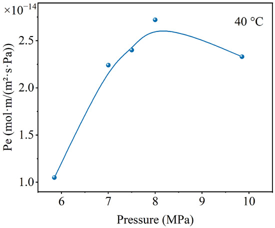
At a constant temperature of 40 °C, the effect of pressure on permeation behavior was first examined. As shown in Figure 5, no leakage was detected at 4 MPa; therefore, the analysis focused on the 6–10 MPa range. During stepwise pressurization, the permeation flux increased with pressure, indicating that hydrogen transport is primarily driven by the pressure gradient.
Figure 5.
Permeability coefficient changes with hydrogen pressure.
However, the permeability coefficient did not exhibit a strictly monotonic increase. Notably, a slight decrease was observed at approximately 9.85 MPa. This behavior suggests that pressure influences not only the driving force but also the material microstructure, thereby affecting gas transport properties.
This phenomenon may be associated with pressure-induced structural change. Under high pressure conditions, the composite structure may undergo interlayer compaction and reduction in free volume, leading to the contraction of diffusion pathways and a decrease in the diffusion coefficient D. The permeability coefficient can be expressed as:
where D is the diffusion coefficient and S is the solubility coefficient. While S typically varies only slightly, D is highly sensitive to structural state. In high-pressure regimes, structural densification reduces D, resulting in a competition between pressure-enhanced driving force (ΔP↑) and diffusion suppression (D↓). This mechanism provides a reasonable explanation for the non-monotonic variation of permeability observed experimentally.
This interpretation is further supported by structural observations. No leakage was detected at the liner–reinforcement interface, and strong interfacial bonding was maintained after long-term testing, indicating that no preferential transport channels are formed. In addition, pressure-induced radial contraction and tighter interlayer packing are expected to further restrict permeation pathways. These factors collectively suggest that the intrinsic barrier performance of the material system remains stable under high-pressure conditions.
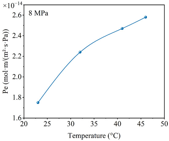
In contrast, temperature exhibited a pronounced effect on permeation behavior under similar pressure conditions (8 MPa). As shown in Figure 6, as temperature increased from 23 °C to 46 °C, the permeability coefficient rose from approximately 1.75 × 10⁻¹⁴ to 2.58 × 10⁻¹⁴ mol·m/(m2·s·Pa). This trend indicates that temperature primarily enhances permeation by accelerating the diffusion process.
Figure 6.
Changes in permeability coefficient with temperature.
Considering the combined effects of pressure and temperature, hydrogen permeation in the composite pipeline can be understood as a coupled multi-factor process governed by: driving force (ΔP), diffusion capability (D), and structural state (free volume). Under low-pressure or low-temperature conditions, permeation is predominantly diffusion-controlled. At high pressure, however, structural densification may partially offset the diffusion-enhancing effect of temperature, leading to a moderated increase in permeation.
Overall, hydrogen permeation in the composite pipeline can be understood as a coupled process governed by pressure-driven transport and structure-dependent diffusion. While pressure increases the driving force for permeation, it may simultaneously induce structural compaction that limits diffusion. As a result, permeation behavior reflects the balance between these competing effects, rather than a simple monotonic dependence on pressure.
4. Design Principles for Composite Hydrogen Pipelines
Based on the experimental results presented above, the fabricated thermoplastic composite hydrogen pipeline indicates excellent operational stability, structural integrity, and safety margins under high-pressure hydrogen environments. To further elucidate the underlying mechanisms enabling stable hydrogen transport and to provide guidance for engineering applications, this section analyzes the system from the perspectives of structural load-bearing mechanisms, hydrogen transport behavior, and deformation–permeation coupling effects. Corresponding design implications are then derived.
4.1. Design Constraints for Hydrogen Pipelines
The design of hydrogen transport pipelines is fundamentally governed by dual constraints: permeation resistance and load-bearing capacity. From a transport perspective, hydrogen is characterized by its small molecular size and high diffusivity, and its permeation behavior is primarily controlled by the solution–diffusion mechanism of the material. Table 3 gives the permeability coefficients of common hydrogen barrier materials. Previous studies have shown that the hydrogen permeability coefficient of typical high-density polyethylene (HDPE) is on the order of 10−13, whereas polyamide materials (e.g., PA12) can reduce this value to below 10−14, exhibiting superior barrier performance. The experimental results of this study further suggest that PA12-based composite structures maintain permeation levels within an engineeringly acceptable range, validating their suitability as liner materials for hydrogen transport.
Table 3.
Permeability coefficients of common hydrogen barrier materials (25 °C).
In terrestrial pipeline systems, metallic barrier layers (e.g., aluminum) are often introduced to further suppress permeation, achieving near-zero hydrogen leakage. However, in offshore flexible pipelines subjected to long-term bending, tension, and dynamic loading, metallic layers are prone to fatigue cracking, leading to barrier failure. Therefore, such configurations are unsuitable for deep-sea hydrogen transport applications that require high flexibility. Under these conditions, pipeline sealing performance must rely on the intrinsic barrier properties of polymers in combination with optimized structural design.
From a structural perspective, hydrogen pipelines typically operate within a pressure range of 5–10 MPa, requiring sufficient resistance to internal pressure-induced deformation and long-term stability. In this study, the filament-wound reinforcement layer, consisting of multiple carbon fiber prepreg layers, provides the primary load-bearing capacity. The experimental results indicate that the current configuration (eight prepreg layers) is capable of maintaining stable deformation behavior within the range of 6–8 MPa. However, at higher pressure levels (e.g., 10 MPa), a transition from stable to accelerated deformation is observed, suggesting that the structural design approaches its performance limit under prolonged loading.
This transition can be interpreted as an important design indicator. Rather than defining safety solely based on the absence of immediate failure, structural integrity should be evaluated based on deformation evolution, particularly the transition from stabilized to accelerated deformation behavior. The identification of such a pressure threshold provides a practical basis for defining safe operating conditions and guiding structural design.
Therefore, for engineering applications, the design of thermoplastic composite hydrogen pipelines should incorporate: (i) the selection of liner materials with sufficiently low permeability (e.g., PA12), (ii) optimization of reinforcement layer configuration to ensure stable deformation under target pressure conditions, and (iii) consideration of long-term deformation behavior in defining safety factors and operating limits. For applications involving higher pressures or longer service durations, further optimization of layer thickness, stacking sequence, and interlaminar properties is required to enhance structural reliability.
4.2. Structural Safety and Failure Mechanisms
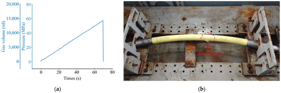
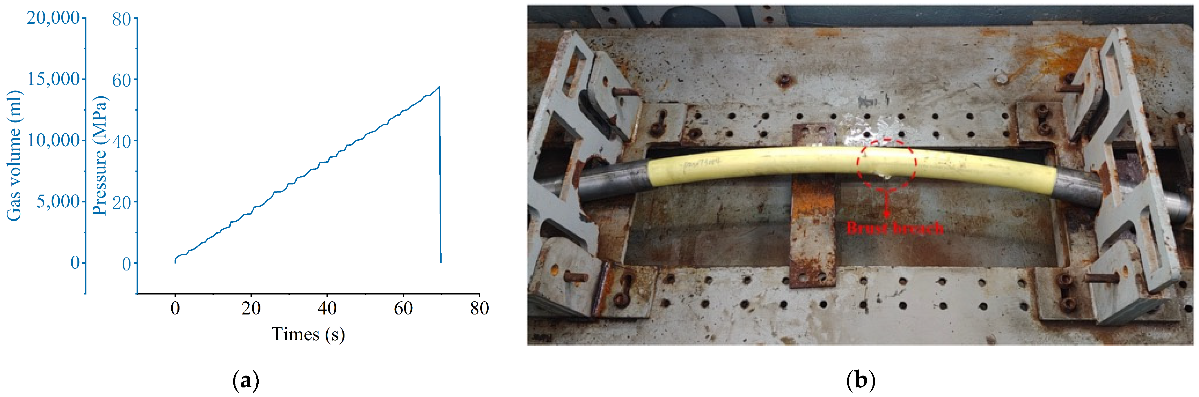
From a structural response perspective, the safety of composite hydrogen pipelines primarily depends on the ability of the reinforcement layer to carry internal pressure loads and constrain deformation. As indicated by the experimental results (Figure 7), the pipeline maintains stable deformation within the operating pressure range and exhibits high burst strength under extreme conditions, demonstrating that the reinforcement layer effectively withstands the dominant load.
Figure 7.
Pipeline burst test. (a) Burst pressure curve; (b) burst breach.
Under internal pressure, the pipeline is mainly subjected to hoop and axial stresses, with an approximate ratio of 2:1. The adoption of a symmetric ±54.7° winding configuration enables fibers to share loads along both principal stress directions, thereby preventing overloading in any single direction. This configuration corresponds to the concept of “equal-strength design”, maximizing fiber load utilization efficiency.
In terms of failure mechanisms, composite pipelines typically fail through reinforcement fracture or interfacial debonding under extreme loading. If the hoop strain exceeds the ultimate capacity of the fibers or matrix, rapid structural failure may occur. Furthermore, under external pressure or bending loads, insufficient structural stiffness may lead to local buckling or interlayer instability. Therefore, the design must ensure that operational strains remain below the yield or damage thresholds under all usage conditions.
The experimental results indicate that the structure possesses significant strength reserves and good fatigue resistance, suggesting that its failure boundary is well beyond the required operating conditions.
4.3. Interlaminar Damage Evolution Under Cyclic Pressure Loading
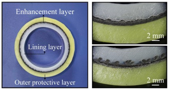
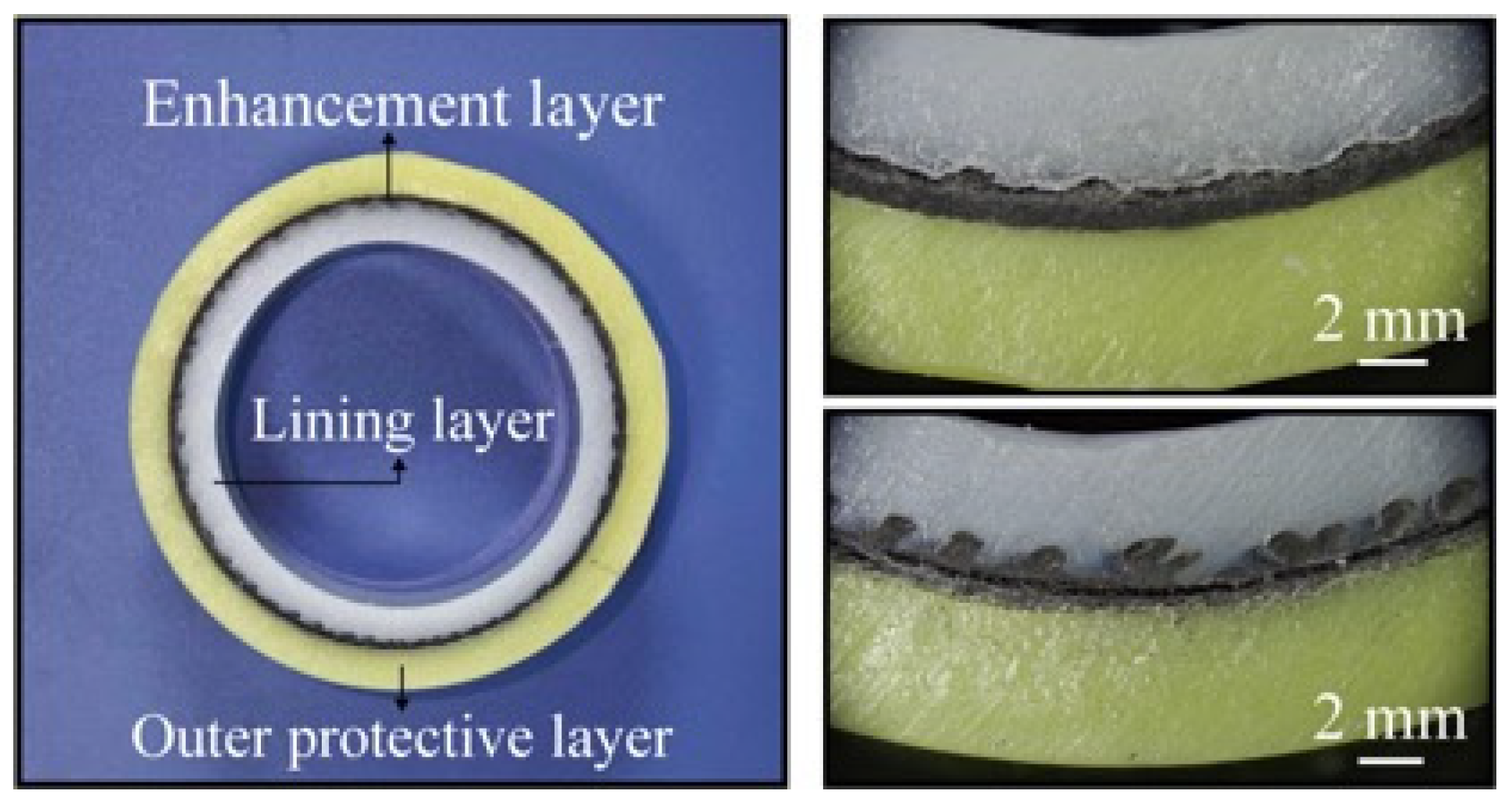
To further evaluate the structural durability of the composite pipeline under realistic service conditions, cyclic pressure loading tests were conducted within a pressure range of 0.5–20 MPa at a frequency of 25 cycles per minute, for a total of 7000 cycles. After testing, cross-sectional specimens were extracted and examined using optical microscopy to characterize damage evolution at different structural interfaces. Representative microstructural features are shown in Figure 8.
Figure 8.
Interlaminar damage after pressure cycling.
As shown in Figure 8, microscopic observations indicate that the liner–reinforcement interface remains generally well bonded after cyclic loading. Carbon fibers within the prepreg layers were found to be embedded into the outer surface of the PA12 liner, suggesting that the interfacial fusion achieved during processing is largely preserved. Although localized separation at the liner–reinforcement interface can be observed in limited regions, these features are discontinuous and are attributed primarily to processing-induced imperfections rather than damage induced by cyclic loading. Importantly, no evidence of continuous interfacial cracking or preferential leakage pathways is detected.
In contrast, the interlaminar regions within the composite reinforcement exhibit clear signs of damage accumulation. As shown in Figure 9, optical microscopy reveals characteristic features of interlaminar tearing, including crack initiation at layer interfaces and propagation across adjacent plies. In several regions, cross-layer tearing morphologies are observed, indicating that damage is not confined to a single interface but can evolve through multiple layers under cyclic loading. These observations suggest that repeated pressure fluctuations lead to progressive stress redistribution and localized strain concentration within the laminate, promoting interlaminar degradation.
Figure 9.
Microscopic image of interlaminar tearing of the reinforcement layer.
From a structural and processing perspective, this behavior highlights a critical distinction. While the liner–reinforcement interface benefits from thermal fusion and exhibits relatively high resistance to cyclic degradation, the interlaminar regions within the filament-wound structure are more sensitive to defects, residual stresses, and imperfect consolidation. As a result, the durability of the composite pipeline is governed not only by global load-bearing capacity, but also by the integrity of interlaminar bonding within the reinforcement layers.
These findings have direct implications for structural design. The observed transition from stable to accelerated deformation at higher pressures, combined with the presence of interlaminar tearing under cyclic loading, indicates that long-term performance is controlled by damage accumulation within the laminate rather than by immediate interface failure. Therefore, improving interlaminar properties—through optimized stacking sequence, enhanced consolidation, and reduced defect density—represents a key pathway for increasing the reliability of thermoplastic composite pipelines.
Overall, the integration of cyclic loading conditions and microstructural observations provides a mechanistic basis for understanding structural degradation in composite hydrogen pipelines and establishes a direct link between manufacturing quality, structural response, and long-term performance. This insight forms an important foundation for the development of standardized design criteria, as discussed in the following section.
4.4. Engineering-Oriented Structural Design Approach
The structural design approach proposed in this study was initially established based on classical thin-walled cylinder theory and composite netting theory, which provide a fundamental basis for evaluating load-bearing capacity and determining layer configuration. This theoretical approach enables the preliminary design of thermoplastic composite pipelines by defining the relationship between internal pressure, structural dimensions, and reinforcement parameters.
However, the experimental results indicate that strength-based design alone is not sufficient to fully characterize the structural performance of thermoplastic composite pipelines under realistic service conditions. In particular, the observed transition from stable to accelerated deformation at elevated pressure, together with the evidence of interlaminar damage under cyclic loading, indicates that deformation evolution and damage accumulation play a critical role in defining structural limits.
Based on these findings, an engineering-oriented design approach is proposed, which integrates three key aspects. First, stress-based analysis provides the baseline for ensuring that the pipeline satisfies basic load-bearing requirements. Second, deformation-based criteria are introduced to define a stable operating regime, where structural response remains bounded and predictable. Third, damage-based considerations—particularly the resistance to interlaminar degradation—are incorporated to evaluate long-term durability under cyclic loading conditions.
From a design perspective, this approach highlights that the allowable operating pressure should be determined not only by the ultimate strength, but also by the onset of accelerated deformation and damage evolution. In addition, the results emphasize that the reliability of thermoplastic composite pipelines is governed more by interlaminar integrity within the reinforcement layers than by the primary liner–reinforcement interface. Therefore, structural optimization should focus on improving interlaminar bonding quality, reducing processing-induced defects, and enhancing resistance to cyclic loading.
Compared with existing design approaches for metallic pipelines or thermoset composite pressure vessels, which are predominantly strength-based, the present approach provides a more comprehensive methodology tailored to thermoplastic composite systems. It establishes a direct link between structural design, deformation behavior, permeation performance, and damage evolution, thereby bridging the gap between material-level characterization and system-level engineering application.
At the same time, it should be noted that the present approach is developed based on a specific structural configuration and a limited set of experimental conditions. Further validation under different material systems, larger-scale pipelines, and extended service environments is required to refine and generalize the design methodology.
5. Conclusions
This study presents a system-level experimental validation of a thermoplastic composite hydrogen pipeline under high-pressure conditions, bridging the gap between material-level characterization and engineering application. A full-scale DN50 pipeline with a PA12 liner and ±54° filament-wound carbon fiber reinforcement was designed and tested under multi-stage pressure loading and cyclic conditions. The results indicate that the pipeline maintains stable deformation and low hydrogen permeation within the investigated pressure range, with permeability on the order of 10−14 mol·m/(m2·s·Pa). A clear transition from stable to accelerated deformation was observed at elevated pressure, indicating the existence of a structural operating limit. Post-test microscopic observations further reveal that while the liner–reinforcement interface remains generally intact, interlaminar damage, including delamination and cross-layer tearing, develops within the composite reinforcement under cyclic loading.
From an engineering perspective, the results highlight that structural performance cannot be evaluated solely based on strength or the absence of immediate failure. Instead, deformation evolution and damage accumulation provide more relevant criteria for defining long-term stability. In particular, the identified transition point (approximately 8 MPa for the present configuration) provides a practical basis for determining safe operating limits. In addition, the findings indicate that long-term durability is governed primarily by interlaminar integrity rather than by failure at the primary interface, emphasizing the importance of interlaminar design and processing quality. Based on these insights, a design framework integrating stress-based analysis, deformation-based criteria, and damage-based evaluation is proposed. Overall, this work suggests the feasibility of thermoplastic composite pipelines for hydrogen transport while also identifying key limitations and directions for further optimization, including interlaminar performance, extended long-term testing, and multi-field coupled evaluation.
Author Contributions
Conceptualization, P.X. and C.Z.; methodology, P.X. and L.X.; software, L.X.; validation, L.X., Q.W. and X.L.; formal analysis, P.X. and L.X.; investigation, P.X., X.L. and C.Z.; resources, P.X. and C.Z.; data curation, P.X. and C.Z.; writing—original draft preparation, P.X. and C.Z.; writing—review and editing, L.X. and X.L.; visualization, X.Z. and Q.W.; supervision, P.X. and C.Z.; project administration, P.X. and C.Z.; funding acquisition, P.X. and C.Z. All authors have read and agreed to the published version of the manuscript.
Funding
This work was supported by the Key Program of Advanced Ocean Institute of Southeast University Nantong (KP202401), the Frontier Technology Research and Development Program of Jiangsu Province (BF2024037), and the Jiangsu Zhengdao Ocean Technology Co., Ltd. Project (H202520836).
Data Availability Statement
Data will be made available on request.
Acknowledgments
This research was supported by high-pressure hydrogen testing technology provided by the Central Research Institute of China State Power Investment Corporation.
Conflicts of Interest
Pingyuan Xia, Xiaolin Zhu, Qingxia Wang, and Xiaomin Lu are employed by Jiangsu Zhengdao Ocean Technology Co., Ltd. Pingyuan Xia and Chen Zhang have received research funding from this company. The hydrogen transmission pipeline used in this study was provided by Jiangsu Zhengdao Ocean Technology Co., Ltd. The funding sponsor participated in the study design and data collection, but had no role in the interpretation of data, manuscript writing, or the decision to publish the results.
References
- Li, X.G.; Du, Y.D.; Tan, Z.F.; He, H.; Fan, W. Optimal operation model of electrothermal integrated energy system including hydrogen production from offshore wind power participating in multi-level market. Int. J. Hydrogen Energy 2025, 114, 250–266. [Google Scholar] [CrossRef] [Scilit]
- Sarker, A.K.; Azad, A.; Rasul, M.G.; Doppalapudi, A.T. Prospect of Green Hydrogen Generation from Hybrid Renewable Energy Sources: A Review. Energies 2023, 16, 1556. [Google Scholar] [CrossRef] [Scilit]
- Travaglini, R.; Superchi, F.; Lanni, F.; Manzini, G.; Serri, L.; Bianchini, A. Towards the development of offshore wind farms in the Mediterranean Sea: A techno-economic analysis including green hydrogen production during curtailments. IET Renew. Power Gener. 2024, 18, 3112–3126. [Google Scholar] [CrossRef] [Scilit]
- D’Amore-Domenech, R.; Leo, T.J.; Pollet, B.G. Bulk power transmission at sea: Life cycle cost comparison of electricity and hydrogen as energy vectors. Appl. Energy 2021, 288, 116625. [Google Scholar] [CrossRef] [Scilit]
- Glaum, P.; Neumann, F.; Brown, T. Offshore power and hydrogen networks for Europe’s North Sea. Appl. Energy 2024, 369, 123530. [Google Scholar] [CrossRef] [Scilit]
- Atiz, A.; Erden, M.; Karakilcik, H.; Karakilcik, M. Integrating renewable energy technologies in green ships for mobile hydrogen, electricity, and freshwater generation. Int. J. Hydrogen Energy 2024, 89, 1368–1382. [Google Scholar] [CrossRef] [Scilit]
- Wang, H.T.; Tong, Z.; Zhou, G.J.; Zhang, C.; Zhou, H.Y.; Wang, Y.; Zheng, W.Y. Research and demonstration on hydrogen compatibility of pipelines: A review of current status and challenges. Int. J. Hydrogen Energy 2022, 47, 28585–28604. [Google Scholar] [CrossRef] [Scilit]
- Ning, Y.X.; Yang, P.X.; Song, M.; Wang, Y.; Li, Y.X.; Liu, C.W.; Wang, C.L. Investigation on hydrogen embrittlement behaviour of X65 steel base metal and girth weld metal under in-situ hydrogen environment. Corros. Sci. 2026, 261, 113625. [Google Scholar] [CrossRef] [Scilit]
- Huang, S.; Zhang, Y.L.; Yang, C.; Hu, H. Fracture strain model for hydrogen embrittlement based on hydrogen enhanced localized plasticity mechanism. Int. J. Hydrogen Energy 2020, 45, 25541–25554. [Google Scholar] [CrossRef] [Scilit]
- Yang, Y.F.; Nair, A.K.N.; Sun, S.Y. Sorption and Diffusion of Methane, Carbon Dioxide, and Their Mixture in Amorphous Polyethylene at High Pressures and Temperatures. Ind. Eng. Chem. Res. 2021, 60, 7729–7738. [Google Scholar] [CrossRef] [Scilit]
- Tian, H.F.; Guan, F.; Wan, F.; Yang, Y.Q.; Liu, W. The effect of corrosion defects on the collapse pressure of submarine pipelines. Ocean Eng. 2024, 310, 118647. [Google Scholar] [CrossRef] [Scilit]
- Diler, E.; Larché, N.; Thierry, D. Carbon Steel Corrosion and Cathodic Protection Data in Deep North Atlantic Ocean. Corrosion 2020, 76. [Google Scholar] [CrossRef] [Scilit]
- Elkelity, A.; Cao, Y.; El-Wazery, M.; Bai, Y.; Wang, F. Effect of Fiber Reinforcement Flexible Pipeline on Hydrogen Transportation-A Review. Results Eng. 2025, 26, 105299. [Google Scholar] [CrossRef] [Scilit]
- Karim, M.A.; Abdullah, M.Z.; Deifalla, A.F.; Azab, M.; Waqar, A. An assessment of the processing parameters and application of fibre-reinforced polymers (FRPs) in the petroleum and natural gas industries: A review. Results Eng. 2023, 18, 101091. [Google Scholar] [CrossRef] [Scilit]
- Liu, M.F.; Lin, K.L.; Zhou, M.Y.; Wallwork, A.; Bissett, M.A.; Young, R.J.; Kinloch, I.A. Mechanism of gas barrier imsupportment of graphene/polypropylene nanocomposites for new-generation light-weight hydrogen storage. Compos. Sci. Technol. 2024, 249, 110483. [Google Scholar]
- Wang, S.Y. Blending hydrogen in urban gas pipeline system: Investigation of the hydrogen compatibility of PE pipeline material. J. Pipeline Sci. Eng. 2026, 6, 100297. [Google Scholar] [CrossRef] [Scilit]
- Zhao, J.C.; Ding, G.Z.; Feng, P.; Wu, C. High-pressure hydrogen effects on thermoplastics: A comprehensive review of permeation, decompression failure, and mechanical properties. Adv. Ind. Eng. Polym. Res. 2025, 8, 387–407. [Google Scholar] [CrossRef] [Scilit]
- Gul, W.; Xia, Y.E.; Gérard, P.; Ha, S.K. Characterization of Polymeric Composites for Hydrogen Tank. Polymers 2023, 15, 3716. [Google Scholar] [CrossRef] [Scilit]
- Wang, Y.Y.; Hu, Y.D.; Zhang, K.; An, W.Z.; Zhou, H.C.; Lin, Z.Q.; Estefen, S.F. The impact of filament winding configurations on the ultimate load-bearing capacity of non-metallic flexible pipes. Ocean Eng. 2025, 341, 122516. [Google Scholar] [CrossRef] [Scilit]
- Petkoska, A.T.; Samakoski, B.; Azmanoska, B.S.; Velkovska, V. Towpreg-An Advanced Composite Material with a Potential for Pressurized Hydrogen Storage Vessels. J. Compos. Sci. 2024, 8, 374. [Google Scholar] [CrossRef] [Scilit]
- Kulkarni, S.S.; Choi, K.S.; Kuang, W.B.; Menon, N.; Mills, B.; Soulami, A.; Simmons, K. Damage evolution in polymer due to exposure to high-pressure hydrogen gas. Int. J. Hydrogen Energy 2021, 46, 19001–19022. [Google Scholar] [CrossRef] [Scilit]
- Dagdag, O.; Kim, H. Recent Advances in the Hydrogen Gas Barrier Performance of Polymer Liners and Composites for Type IV Hydrogen Storage Tanks: Fabrication, Properties, and Molecular Modeling. Polymers 2025, 17, 1231. [Google Scholar] [CrossRef] [Scilit]
- Dawicka, N.; Kurc, B.; Gross, X.; Tomasz, J.; Siwinska-Ciesielczyk, K.; Kolodziejczak-Radzimska, A. Analysis of the Strength of Polyamide Used for High Pressure Transmission of Hydrogen on the Example of Reinforced Plastic Hoses. Materials 2025, 18, 1402. [Google Scholar] [CrossRef] [Scilit]
- Ding, G.Z.; Tam, L.H.; Wu, C. Molecular investigation on physical and tensile properties of polyethylene (PE) under high-pressure hydrogen environments. Int. J. Hydrogen Energy 2024, 86, 1036–1050. [Google Scholar]
- Ding, G.Z.; Tighe, C.J.; Tam, L.H.; Wu, C. Molecular study of high-pressure hydrogen decompression in amorphous polyethylene. Int. J. Hydrogen Energy 2025, 114, 267–278. [Google Scholar] [CrossRef] [Scilit]
- Zhang, H.L.; Lin, Y.H.; Xiao, J.; Liu, W.C.; Hu, W.T.; Li, T.L. Unveiling the Microstructural Origins of Hydrogen Barrier Superiority in HDPE over PP: Advanced In-Situ Testing and Molecular Dynamics Simulations for Pipeline Applications. Ind. Eng. Chem. Res. 2025, 64, 21293–21306. [Google Scholar] [CrossRef] [Scilit]
- Oz, F.E.; Wagih, A.; Joarder, B.; Datta, S.J.; Eddaoudi, M.; Lubineau, G. Microstructure-driven hydrogen permeability in thin-ply thermoplastic composites: Insights for Type V storage tanks. Compos. Part A Appl. Sci. Manuf. 2026, 200, 109316. [Google Scholar]
- Balasooriya, W.; Clute, C.; Schrittesser, B.; Pinter, G. A Review on Applicability, Limitations, and Imsupportments of Polymeric Materials in High-Pressure Hydrogen Gas Atmospheres. Polym. Rev. 2022, 62, 175–209. [Google Scholar]
- Kuang, W.B.; Nickerson, E.K.; Shin, Y.; Taufique, M.F.N.; Clelland, D.T.; Seffens, R.J.; Simmons, K.L. In situ investigation of high-pressure hydrogen-induced swelling in elastomers and its correlation with material properties. Int. J. Hydrogen Energy 2025, 179, 151315. [Google Scholar]
- Chakraverty, A.P.; Dash, S.; Maharana, H.S.; Beura, S.; Mohanty, U.K. A novel investigation on durability of GRE composite pipe for prolonged sea water transportation. Compos. Commun. 2020, 17, 42–50. [Google Scholar] [CrossRef] [Scilit]
- Bahaman, U.S.F.; Mustaffa, Z.; Ben Seghier, M.E.; Badri, T.M. Evaluating the reliability and integrity of composite pipelines in the oil and gas sector: A scientometric and systematic analysis. Ocean Eng. 2024, 303, 117773. [Google Scholar] [CrossRef] [Scilit]



Disclaimer/Publisher’s Note: The statements, opinions and data contained in all publications are solely those of the individual author(s) and contributor(s) and not of MDPI and/or the editor(s). MDPI and/or the editor(s) disclaim responsibility for any injury to people or property resulting from any ideas, methods, instructions or products referred to in the content. |
© 2026 by the authors. Licensee MDPI, Basel, Switzerland. This article is an open access article distributed under the terms and conditions of the Creative Commons Attribution (CC BY) license.