1. Introduction
As a fast and controllable power source, energy storage devices play a crucial energy buffering role in the increasingly complex source–grid–load system [
1]. Unlike traditional large-capacity, centralized energy storage power stations, the concept of distributed energy storage is gradually emerging [
2]. Installing energy storage systems in distribution substations not only reduces the AC voltage stress and peak capacity of the equipment but also improves the frequency regulation capability of thermal power units and enhances regional power quality. Therefore, employing energy storage systems to assist thermal power units in frequency regulation and to provide emergency balancing control is of great significance for improving the operational performance of large-scale power distribution systems.
Cascaded H-bridge-based converters are the prevailing topology for energy storage converters nowadays [
3]. In this type of scheme, each energy storage battery can be connected directly to the DC side of the H-bridge, or indirectly via a DC converter, thereby enabling voltage and current sharing between the multiple batteries. Ref. [
4] proposes a novel power management device that connects supercapacitors directly to a 10 kV distribution grid via cascaded H-bridge converters, but it does not involve the analysis and optimization of energy storage costs and device efficiency. Different from this approach, Ref. [
5] integrates supercapacitor cells and photovoltaic modules into a single-phase grid-connected photovoltaic inverter via cascaded H-bridge converters, aiming to stabilize active power fluctuations when illumination varies. However, no detailed modulation and triggering methods are provided, leaving the pulse triggering of the H-bridge containing supercapacitors and its coordination with the other H-bridges unclear. Under similar design considerations, the energy storage system integrating supercapacitors via cascaded H-bridges is also reported in Ref. [
6], yet the voltage drop across the equivalent inductance of the interface transformer is ignored in the voltage dynamics analysis, and the selected high-voltage supercapacitor modules are difficult to obtain. Furthermore, classic control strategies, such as the SOC balancing algorithm [
7] and the auxiliary voltage balancing loop [
8], are susceptible to interaction with carrier phase-shift modulation [
9], which alters the phase-shift relationship between the output voltages of the sub-modules [
10], thereby undermining the inherent advantages of carrier phase-shift modulation and increasing the harmonic component of the output current in the cascaded H-bridge converter.
However, the above investigations cannot be directly applied to frequency support applications, as the specific demands of low-voltage, high-current conditions in distribution systems have not been adequately considered. On the one hand, numerous series-connected H-bridges are required to integrate supercapacitors into the AC bus, where the energy storage converter is already capable of outputting substantial voltage levels, rendering any further increase in voltage levels unnecessary [
11,
12,
13]. In fact, the classic two-level converter is sufficient to meet power quality requirements, and employing the cascaded H-bridge converter could instead significantly increase the cost of the system. Recent studies have attempted to reduce system cost through hybrid topologies. For instance, a cascaded hybrid H-bridge where a high-frequency capacitor submodule is series-connected with multiple low-frequency battery submodules is proposed to reduce switching losses and allow the use of lower-cost power devices [
14]. However, this scheme still requires each submodule to contain an individual DC-DC converter, leaving the overall control complexity and hardware redundancy largely unresolved. Similarly, Ref. [
15] presents a current-fed quadruple active bridge-based cascaded H-bridge architecture that reduces the number of active switches by approximately 20% compared to classic solutions, but the four DC ports remain strongly coupled, necessitating complex decoupling control that does not simultaneously mitigate the high current through the storage modules. On the other hand, high-current output results in significant power losses, which can cause batteries or supercapacitors to overheat, posing a safety hazard. While novel overmodulation strategies have been proposed to extend the operating range of cascaded H-bridge converters under deep charge/discharge conditions by selectively over-modulating heavily loaded submodules while compensating distortions in other phases [
16], these methods focus solely on power distribution and fail to address the root cause of losses—the excessive current magnitude flowing through the storage modules. Likewise, advanced SOC balancing algorithms, such as the dual-stage model predictive control developed for second-life battery cascaded H-bridge systems, can optimize charging/discharging current distribution among submodules [
17]. Nevertheless, such SOC-oriented strategies do not resolve the fundamental DC voltage regulation limitation of classic cascaded H-bridge topologies; each H-bridge submodule must still handle high current, leading to substantial internal resistance losses and thermal stress.
Summarizing the above research, cascaded H-bridges can actively achieve voltage and current balancing between batteries or supercapacitors, but the excessive number of submodules leads to high device costs. For this reason, this paper innovatively connects cascaded H-bridges in series to form a controllable DC bus, thereby preserving the voltage and current balancing capabilities of batteries or supercapacitors. This configuration is then connected in parallel with a classic two-level converter, whose sinusoidal current output and fault ride-through capability ensure the safe and stable operation of the entire energy storage system. The contributions of the proposed method are listed as follows:
Retains the voltage and current sharing between batteries or supercapacitors, while reducing the number of H-bridges.
Reduced current flowing through batteries or supercapacitors, thereby decreasing the loss and heat issues of the device.
2. Classic Energy Storage Converter Based on Cascade H-Bridges
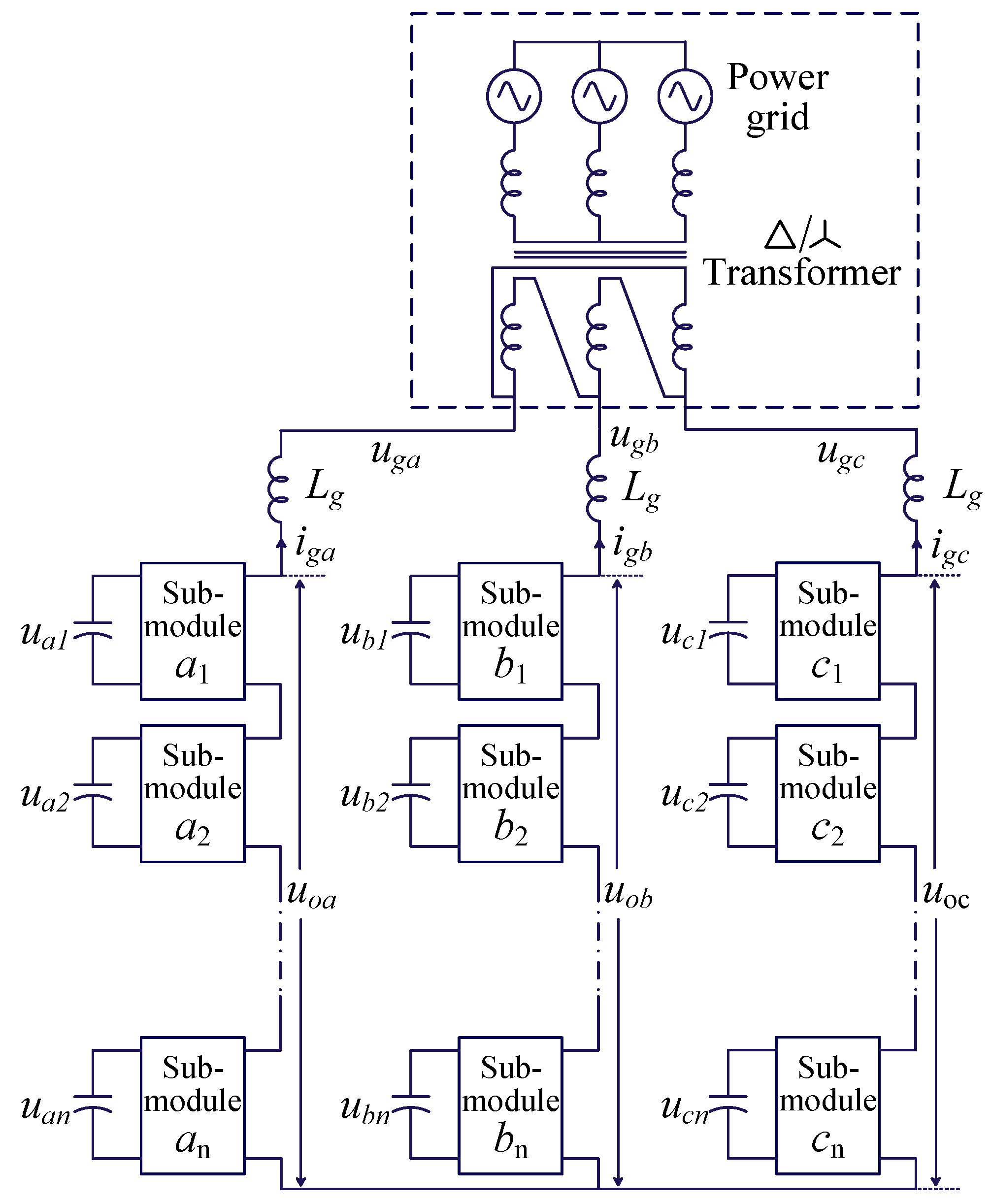
The basic topology of the cascaded H-bridge converter is shown in
Figure 1 [
18]. In this figure,
ugj and
igj represent the grid voltage and current of phase
j,
ujk presents the input voltage of the k submodule of phase
j,
uoj represents the output voltage of the phase
j cascaded converter branch, and
Lg is the filter inductor (
j = A, B, C;
k = 1, 2, …,
n).
Figure 1 shows that the cascaded H-bridge converter mainly consists of multiple submodules. Submodules are connected in series to form a single-phase cascade branch, and three such single-phase branches form a three-phase cascaded converter. Each submodule is connected to a supercapacitor, whose rapid charging and discharging capabilities can enhance the dynamic response of the energy storage converter.
Due to the low capacity of single energy storage modules, numerous modules are required for high-power systems, which means the system itself is capable of outputting numerous voltage levels. To reduce system costs, the minimum number of H-bridges can be derived as follows.
The total energy constraint for supercapacitors is
where
ntot denotes the total type of supercapacitors,
xi,
yi, and
Esc0 are the series number, parallel number, and rated capacity of type
i, respectively,
Tdis is the discharge duration,
Pgref is the active power reference value, and
km1 represents the capacity margin.
Define the phasor form of uoj as uo, ugj as ug, and igj as ig, respectively. The phasor relationships on the AC side can be expressed as:
The amplitude of (2) is
where
Vo is the amplitude of
uo.
Given the modulation ratio margin
km2, (3) can be simplified to
where
Vdcmin is the minimum total DC voltage,
Vg is the amplitude of
ug, and
ω is the angular velocity of the grid voltage.
According to (4), the voltage constraint for series-connected supercapacitors can be expressed as
where
Usc0 denotes the rated voltage of supercapacitor
i.
Combining (1), (4), and (5), the basic constraints for the above-mentioned cascaded H-bridge converter are as follows:
It is worth noting that the three arms of the cascaded H-bridge converter shown in
Figure 1 are parallel-connected, implying that the minimum number of submodules is 3∑
xi, which will significantly increase the cost of the energy storage converter.
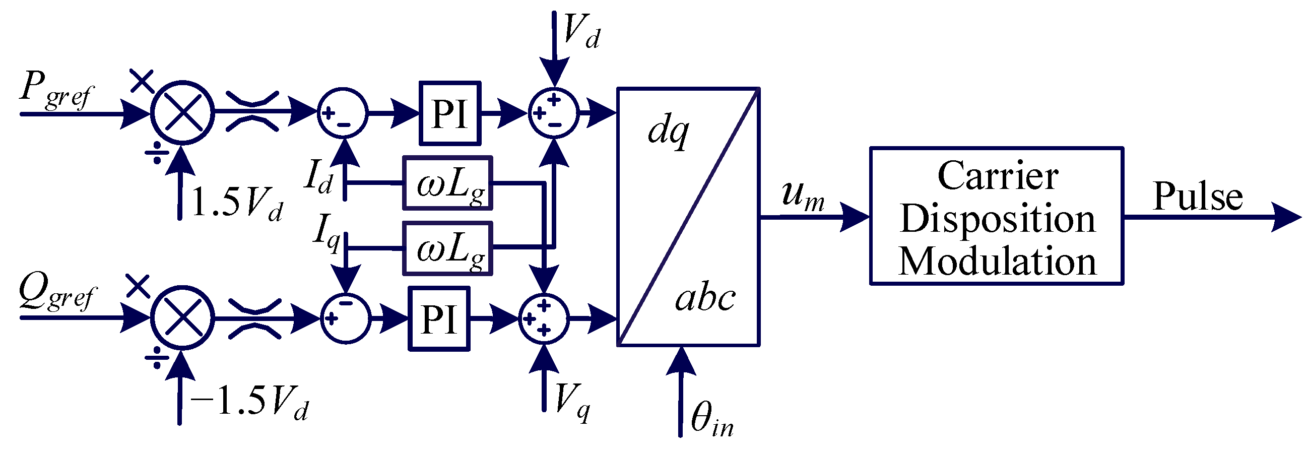
On the other hand, the vector current control method shown in
Figure 2 is generally used for energy storage converters, where
Qgref is the reference value for the output reactive power,
θin is the phase angle of
ug, and
um is the modulation wave output by the vector current control.
3. Dynamic Analysis of Classic Energy Storage Devices
3.1. Losses of Classic Energy Storage Converters
The losses in energy storage systems primarily originate from the equivalent internal resistance of the batteries or supercapacitors. The specifications for real supercapacitor products can be found in
Table 1, served as an example for the loss analysis of energy storage devices in this section.
In
Table 1,
Vg is the voltage amplitude on the low-voltage side of the transformer shown in
Figure 1, while
Csc0 and
Rsc0 denote the capacitance and internal resistance of a specific supercapacitor.
Combining (6) and
Table 1, 10 submodules are required per arm when employing the cascaded H-bridge converter shown in
Figure 1, with each sub-module connected to a supercapacitor. Under this scenario, the magnitude of the output current from the energy storage converter can be calculated using the following equation:
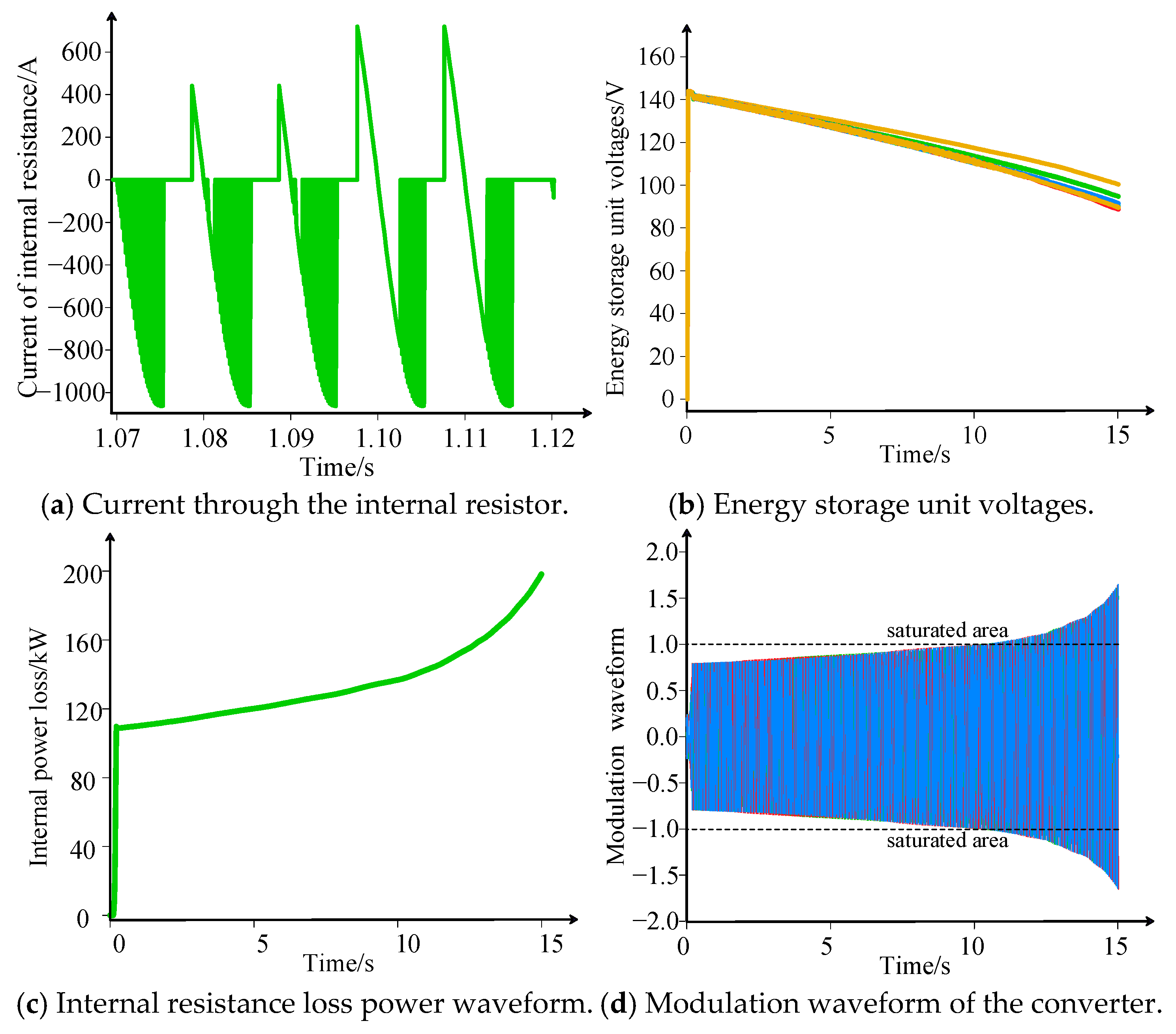
Based on (7), it can be calculated that the amplitude of output current from the energy storage converter during steady-state operation reaches 1.07 kA. Under these operating conditions, large currents will flow through the internal resistance of the energy storage module, as shown in
Figure 3a, resulting in high losses. Combined with
Figure 3b, the terminal voltage of the energy storage modules drops as they discharge continuously; their output current will further increase to maintain a constant power supply, which will consequently increase power losses.
The losses across the internal resistor of energy storage modules are measured and plotted in
Figure 3c, indicating that losses rise from the initial 20% to 39.62%, resulting in significant power wastage and heat dissipation requirements. Moreover, it shows that losses rise rapidly in the final stage, attributable to the saturation of the modulating waveform caused by the excessively low voltage of the energy storage module, as depicted in
Figure 3d, where the converter outputs distorted current with an ever-increasing amplitude, resulting in further losses.
Therefore, the classic cascaded H-bridge-based energy storage converter suffers from significant losses and heat dissipation issues in low-voltage, high-current applications, primarily due to the excessive current flowing through the energy storage modules and the absence of DC voltage regulation capability.
3.2. Bidirectional Voltage Regulation of Energy Storage Modules
The second equation in (6) shows that a sufficient DC voltage is required to modulate an AC voltage. However, as the supercapacitor continues to discharge, its terminal voltage decreases continuously, which would violate (6). Therefore, a DC converter is recommended to be incorporated into the sub-module of the cascaded H-bridge converter.
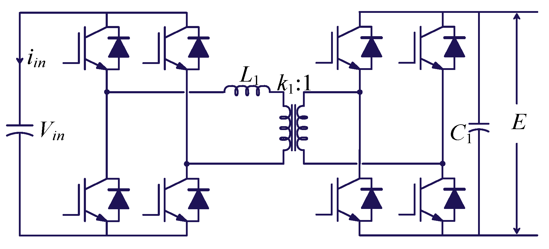
The dual active bridge (DAB) converter is a commonly used DC converter, with its block diagram shown in
Figure 4 [
19]. In this diagram,
iin is the input current to the energy storage module, whilst
L1,
k1 and C
1 represent the leakage inductance, turns ratio, and filter capacitor of the DAB, respectively, and
Vin and
E are the input and output voltages of the DAB converter, respectively.
The output power of the DAB converter can be expressed as
where
Pdab denotes the DAB output power, and
f1 and
φ1 denote the DAB switching frequency and phase-shift angle, respectively.
When the energy storage module continues to deliver power,
Vin continues to decrease. Combined with (8),
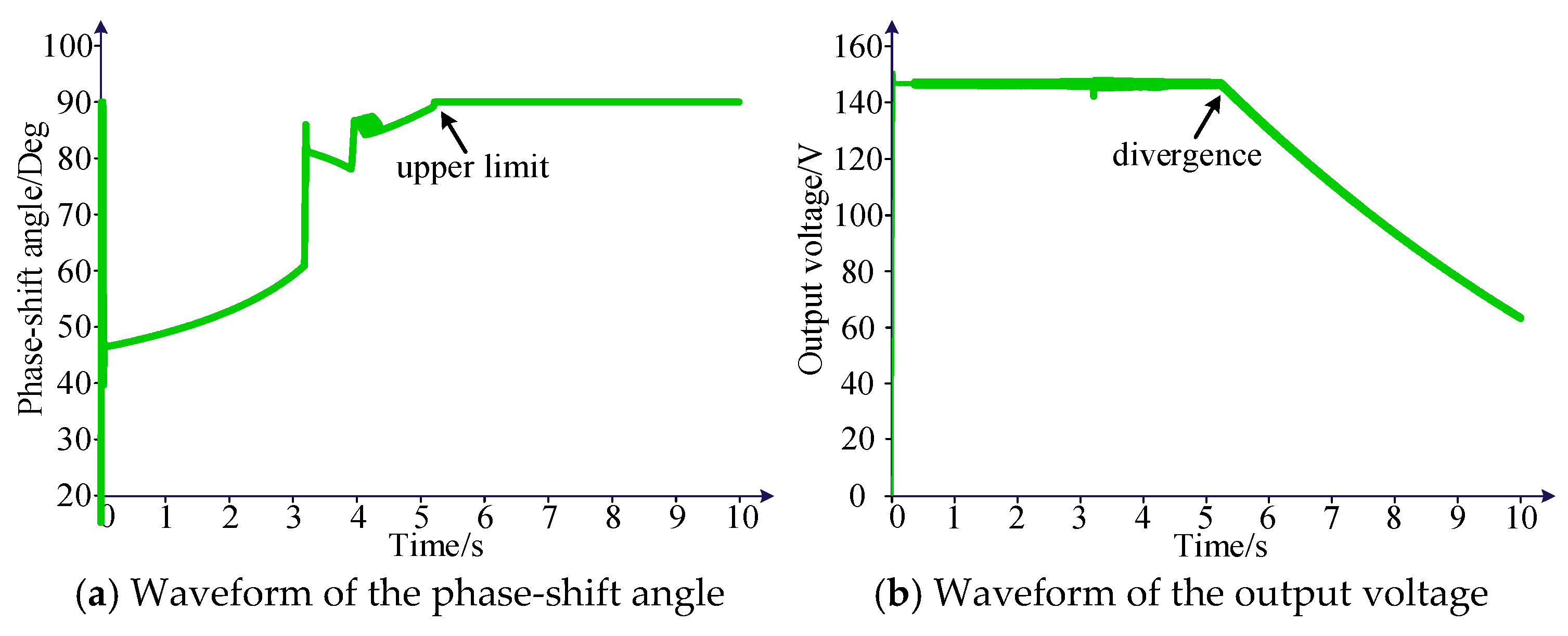
φ1 of the DAB must continue to increase for constant power output, as shown in
Figure 5. When
φ1 increases to π/2,
φ1(π −
φ1) begins to decrease [
20], where the power balance cannot be sustained, and the DAB moves beyond the controllable range. Under these conditions, large current surges will occur at the leakage inductor, which may trigger shutdown protection. Therefore, the maximum operating time of the DAB converter is still limited due to its maximum external phase-shifting angle, even though the operating time of the energy storage converter incorporating it has been extended.
Similar issues also exist in commonly used z-source DC converters. As the supercapacitor continues to discharge, its terminal voltage gradually decreases, resulting in an increasingly higher amplitude of the modulating wave. This reduces the controllability of the z-source converter [
21], eventually making it incapable of generating the modulating signal. As a result, classic energy storage converters still lack sufficient bidirectional voltage regulation capabilities, which limits their continuous power supply duration.
3.3. Overmodulation Operation of the Cascaded H-Bridge Converter
As the supercapacitor continues to discharge, its terminal voltage gradually decreases, causing the amplitude of the modulation wave in the classic energy storage converter shown in
Figure 1 to rise continuously until it reaches saturation. Under these operating conditions, the energy storage converter will operate in the overmodulation region, resulting in distorted output current waveforms.
Considering that the cascaded H-bridge converter shown in
Figure 1 is formed by three parallel arms, double-frequency power fluctuations occur within each arm, which, in turn, affects the voltage of supercapacitors and alters the amplitude of the modulation waveform, making the modulation stage more prone to entering the saturation region. Therefore, the saturated modulation issue in parallel arm-based converters will become more challenging.
4. Proposed Energy Storage Converter Based on Controllable DC Bus
To address the above issues, a novel energy storage converter based on the controllable DC bus is proposed in this section, whose advantages over the classic cascaded H-bridge converter in terms of losses, bidirectional voltage regulation, and saturated modulation are demonstrated in detail.
4.1. Proposed Controllable DC Bus Topology
Regarding the issue of high internal resistance losses, the main reason is the excessive current flowing through the energy storage modules, which results in large voltage drops across the internal resistance of the energy storage batteries or supercapacitors, leading to losses and heat dissipation issues. Considering the double-frequency power fluctuations within single bridge arms, loss reduction over the internal resistance becomes more complex and could exacerbate overmodulation issues.
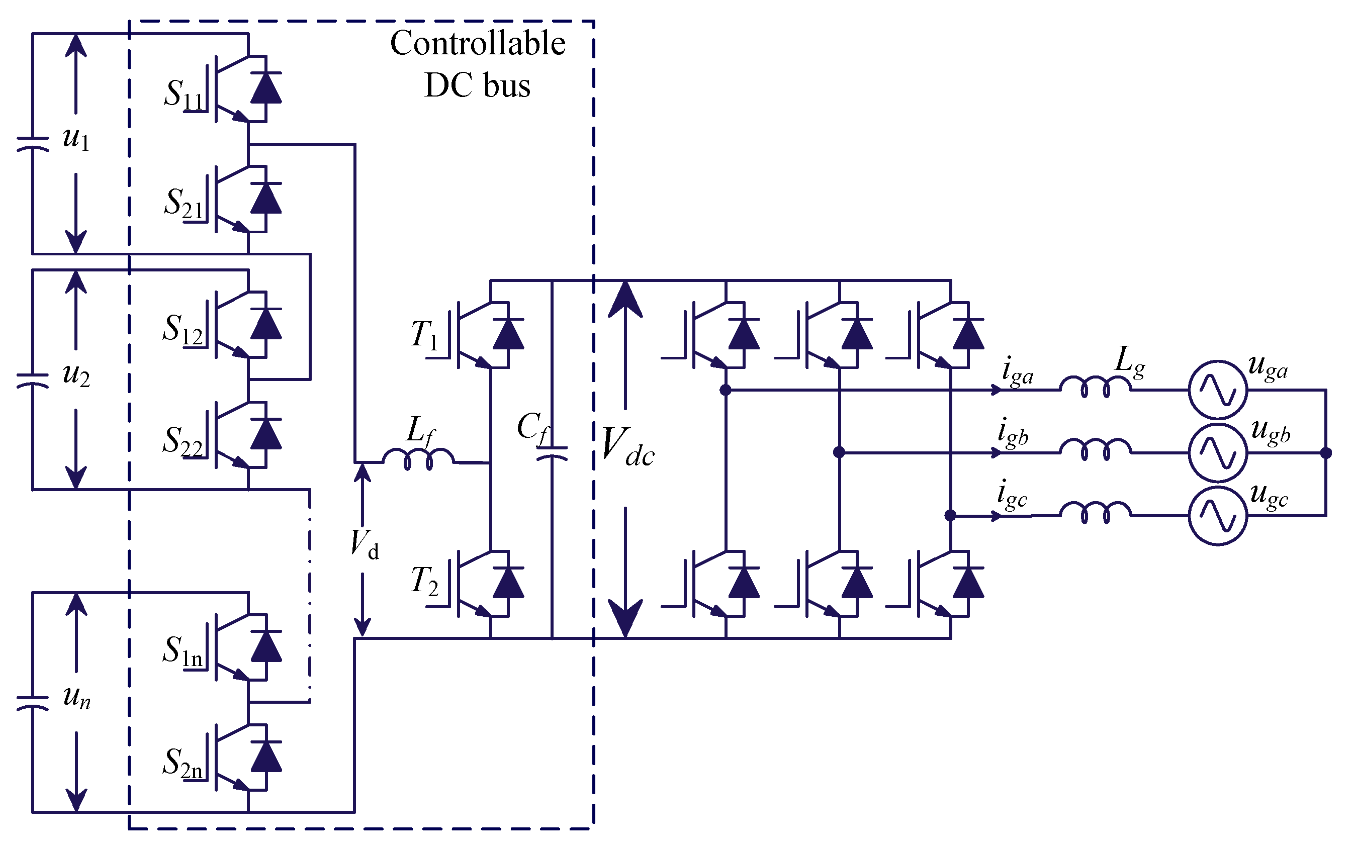
To address this issue, cascaded half-bridges are employed to integrate supercapacitors, which are then connected in parallel with a bidirectional DC converter to form the proposed controlled DC bus. The proposed method not only can significantly increase the DC line voltage—thereby reducing the current flowing through the internal resistance and substantially lowering resistance losses and heat dissipation requirements—but also eliminates frequency-doubling power fluctuations in the cascaded half-bridge submodules, allowing for greatly simplified and improved bidirectional voltage regulation design. Then, the proposed controllable DC bus is connected in parallel with a classic two-level converter to enable grid-connected power transmission and fault ride-through.
The specific structure is shown in
Figure 6, where
Vd is the output voltage of the cascaded structure,
Lf and
Cf are the inductor and capacitor of the bidirectional DC voltage regulation converter,
Vdc is the DC bus voltage,
S1k is the upper switch of the cascaded structure submodule,
S2k is the lower switch of the cascaded structure submodule,
T1 is the upper switch of the bidirectional voltage regulation circuit, and
T2 is the lower switch of the bidirectional voltage regulation circuit.
In the above controllable DC bus, cascaded half-bridges can effectively reduce the output DC voltage Vdc by adjusting the duty cycle, but the absence of energy storage components prevents them from performing a voltage boost. The bidirectional DC converter can effectively boost Vdc through the charging and discharging of the energy storage inductor in boost mode, but the current only flows through the anti-parallel diode T1 in buck mode, making it difficult to enable rapid DC voltage control. Therefore, the proposed controllable DC bus combines the step-down capability of cascaded half-bridges with the step-up capability of bidirectional DC converters. This not only contributes to significantly reducing internal resistance losses, as mentioned earlier, but also enables flexible adjustment of the DC voltage, thereby enhancing the continuous discharge duration of the energy storage system.
Combining (6) with the parameters shown in
Table 1, only 20 supercapacitors are required for the proposed energy storage converter, which is 33% fewer than in the classic scheme shown in
Figure 1. Furthermore, the proposed converter requires only a single bidirectional DC converter, which can save numerous IGBT switchings compared to the classic distributed DC converter-cascaded H-bridge topology [
22].
4.2. Control Method for the Proposed Controllable DC Bus
This paper regards the controllable DC bus shown in
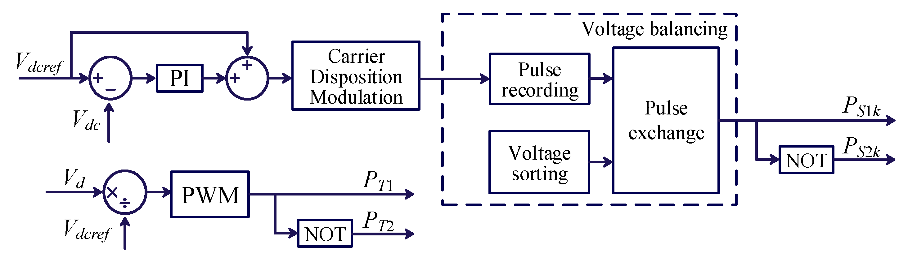
Figure 6 as an entire converter, with its objective being to maintain DC bus voltage across the entire operating range. The detailed control method of the controllable DC bus is as follows, where
Vdcref is the rated value of
Vdc,
PS1k,
PS2k,
PT1 and
PT2 are the pulse signals for
S1k,
S2k,
T1,
PT1 and
T2, respectively, in
Figure 6.
Define the duty cycle of the switching tube
T1 in the bidirectional DC converter in
Figure 6 as
dv. Since the average voltage drop across
Lf is 0 in each switching cycle, the relation between the input and output voltages can be described as:
To control Vdc to Vdcref, (9) can be changed to:
Equation (10) is precisely the pulse generation method for the bidirectional DC converter shown in
Figure 7, which is remarkably simple yet highly effective. On this basis, the DC voltage loop is applied to the cascaded half-bridge, thereby enabling flexible regulation of the DC bus voltage.
4.3. Modulation with Submodule Voltage Balancing
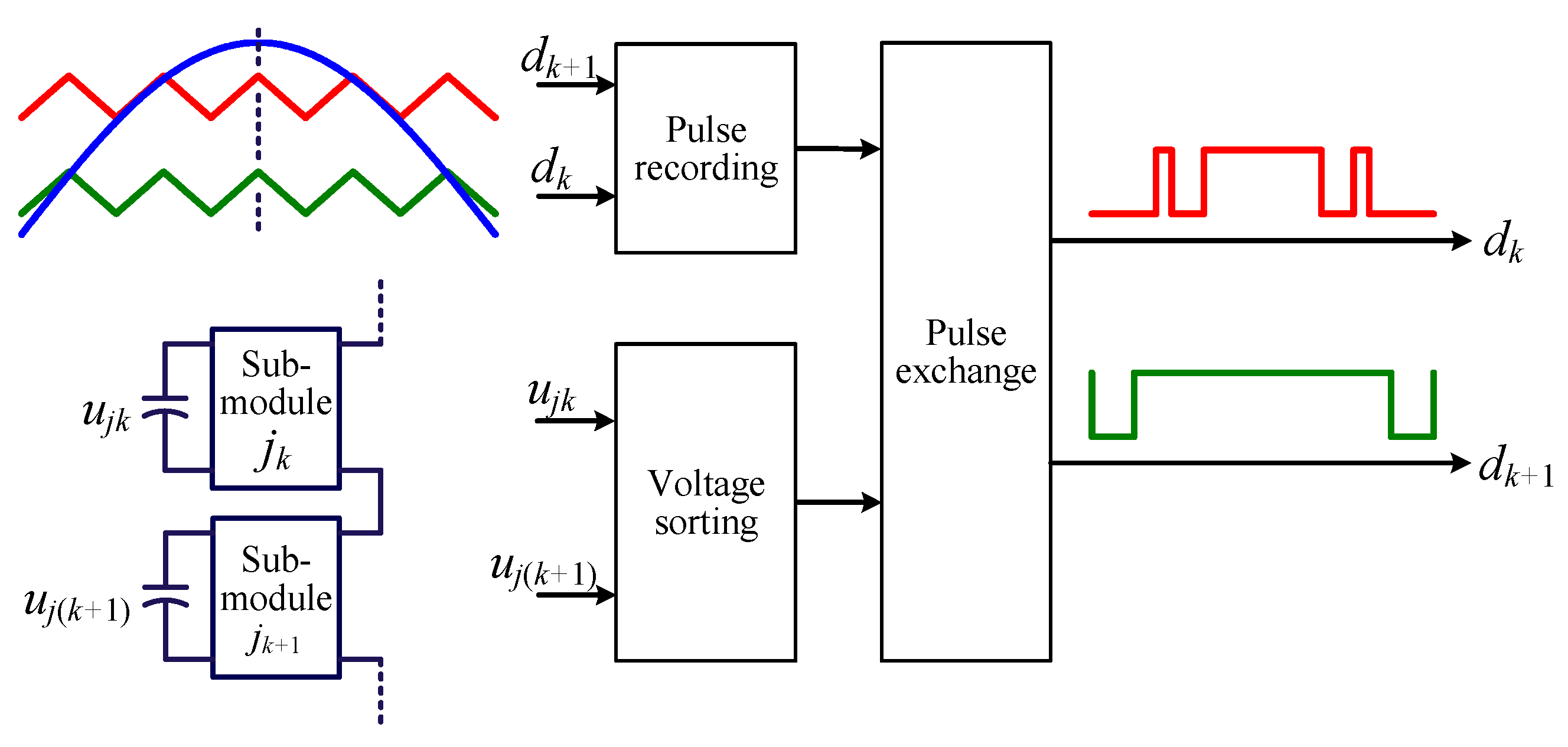
Regarding the voltage balancing of supercapacitors, a simpler but efficient method is proposed based on carrier disposition modulation and voltage sorting [
23]. The details are as follows.
As shown above, the pulse signals of each sub-module generated by carrier-stacked modulation vary significantly, with lower-numbered sub-modules having a higher duty ratio and higher-numbered sub-modules having a lower duty ratio. Under these operating conditions, the bottom-most energy storage modules will exhaust their discharge capacity earlier than others, resulting in a significant imbalance in the charging and discharging depths across the modules, and accelerating the aging of certain modules. After employing the voltage balancing method in
Figure 8, if the magnitude of
ujk is less than that of
uj(k+1), the priority of
ujk in the voltage sorting decreases, while the corresponding carrier layer number increases. Consequently, the duty ratio of sub-module
jk decreases, reducing the reduced discharge of this energy storage module and facilitating its voltage recovery. Similarly, if the amplitude of
ujk is less than that of
uj(k+1) during charging, its priority in the voltage sorting decreases, resulting in a lower carrier layer being used. This increases the duty ratio of sub-module
jk, thereby boosting the charging of that sub-module and promoting its voltage recovery. Therefore, adjusting the carrier layers in which each submodule operates in the carrier disposition modulation provides a convenient way to balance output power among energy storage modules.
5. Discussion and Comparisons
This section compares the energy storage converter based on the proposed controllable DC bus shown in
Figure 6 with the energy storage converter based on the classic cascaded H-bridge shown in
Figure 1, and the results are summarized in
Table 2, where the parameters required for the calculation are also taken from
Table 1.
The classic scheme is formed by cascaded H-bridges, with each submodule requiring four IGBTs. Based on (6) and
Table 1, the number of cascades under this scheme is 10, thereby 30 supercapacitors are required. Therefore, the classic scheme requires a total of 30 × 4 = 120 IGBTs, which significantly increases the cost of the device. Similarly, the proposed scheme requires only 20 half-bridge submodules, combined with a bidirectional DC converter and a two-level converter, for a total of 20 × 2 + 2 + 6 = 48 IGBTs—just 40% of the number used in the previous scheme.
Combining actual IGBT device specifications and the parameters in
Table 1, the total cost analysis is further elaborated with the 500 kW energy storage converter as an example. Under this scenario, the classic topology requires 120 IGBT units rated at 144 V 1071 A, whereas the proposed topology requires 40 IGBT units rated at 144 V 300 A, 2 IGBT units rated at 2.7 kV 300 A, and 6 IGBT units rated at 2.7 kV 1.1 kA. To ensure a fair comparison, the selected IGBT devices are the most cost-effective options available within the specified voltage and current ratings.
Table 3 shows that the total cost of the proposed topology is only 18.18% of that of the classic topology, owing to the replacement of high-current IGBTs with low-current IGBTs. For example, replacing the expensive 1071 A IBGTs with cheaper 300 A IBGTs. Therefore, the cost benefits of the proposed solution are feasible.
Moreover, the maximum loss of the classic scheme, as shown in
Figure 3b above, reaches 39.62%, due to excessively high current flowing through supercapacitors. This current can be greatly reduced by the proposed controllable DC bus, so the proposed scheme exhibits low losses—a notable advantage of the proposed scheme.
In addition, the classic method requires extra voltage balancing methods, such as the SOC balancing algorithm [
7] and the auxiliary voltage balancing loop [
8], but the proposed scheme does not. As shown in
Figure 8, the voltage balancing in the proposed scheme can be integrated into the modulation process, which is very easy to implement and offers faster response capabilities.
Finally, the proposed topology offers similar fault tolerance and short-circuit protection to the classic topology, as both integrate energy storage units through submodules, enabling rapid failure recovery by replacing the submodules. Their output power quality is comparable, and both are capable of four-quadrant power control, since these issues can be easily addressed in low-voltage, high-current applications. Therefore, the cost and loss advantages of the proposed topology will not compromise its performance.
6. Verification of the Proposed Scheme
Based on the topology shown in
Figure 6, the control shown in
Figure 7, the modulation shown in
Figure 8, and the parameters listed in
Table 1, this section validates the effectiveness and performance of the proposed energy storage converter through PLECS.
6.1. Simulation Results of Controllable DC Bus
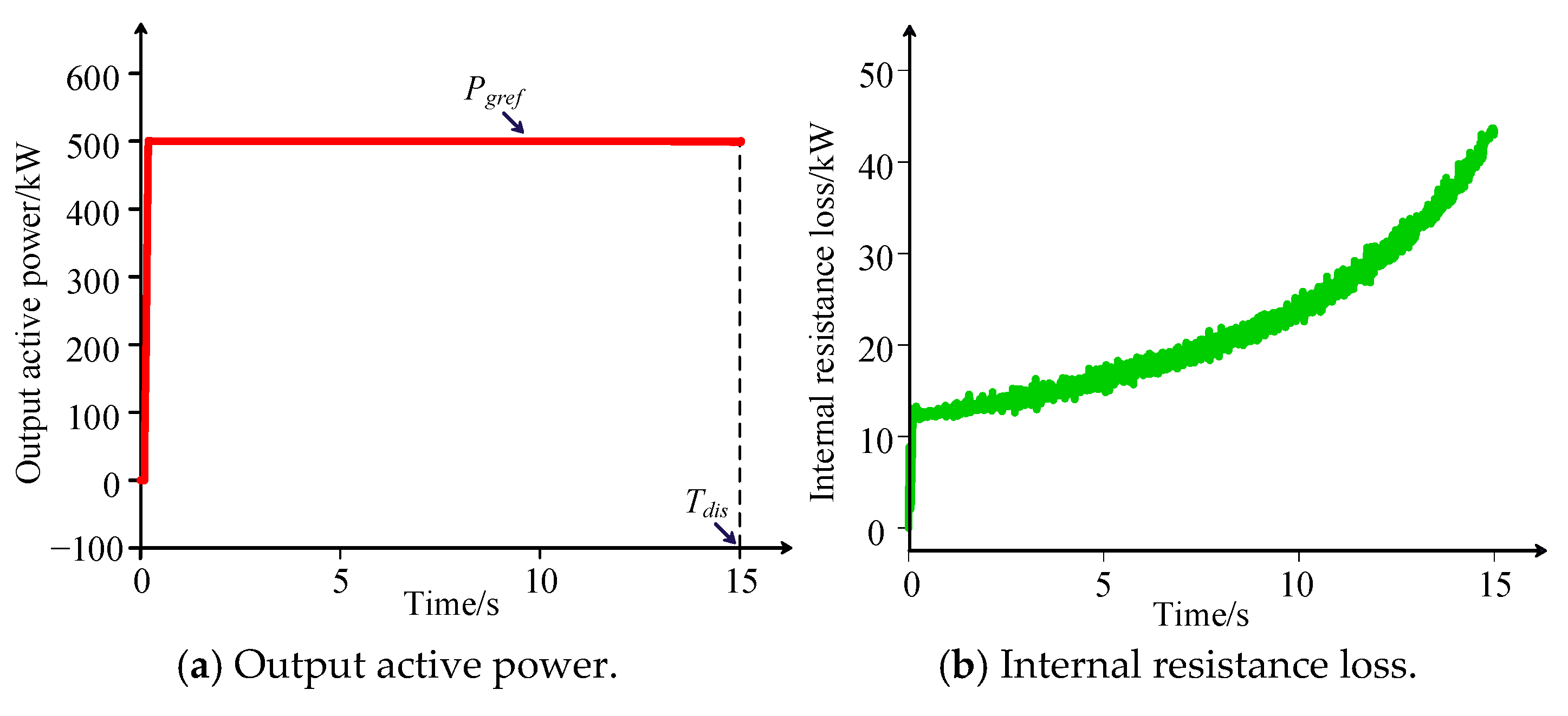
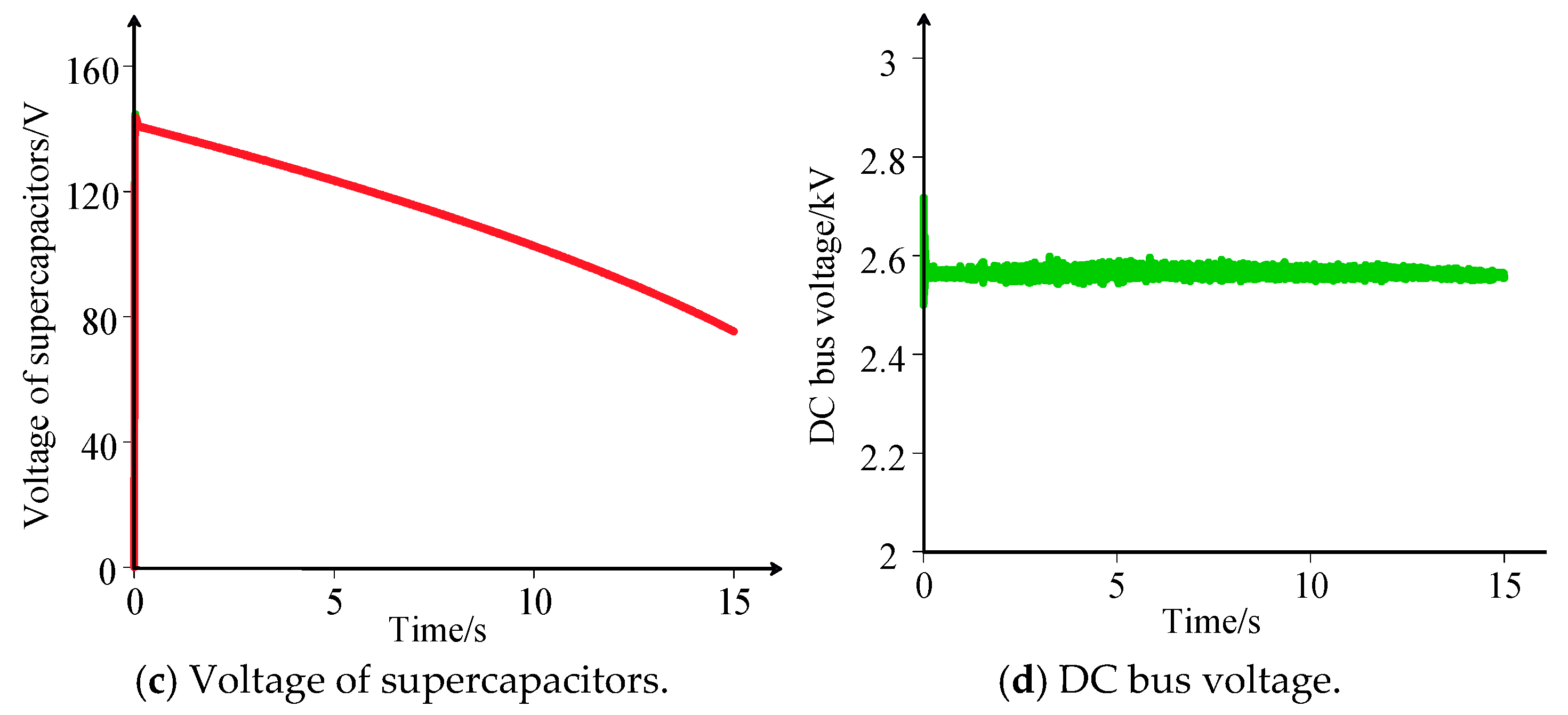
The simulation results for the proposed controllable DC bus are shown in
Figure 9. Among them,
Figure 9a shows that the output active power of the proposed energy storage converter stabilizes at the rated value
Pgref during the rated discharge duration
Tdis, which validates the effectiveness of the energy storage battery selection method presented in (6). Combined with
Table 2, the proposed scheme can reduce 33% supercapacitors and 60% IGBT switchings, exhibiting excellent cost-effectiveness.
From
Figure 9b, internal resistance losses account for only 2.4% to 8.67% of the rated power, which is significantly lower than the 21.74% to 39.62% reported in
Figure 3; thus, the proposed scheme exhibits superior efficiency compared to the classic scheme. In addition,
Figure 9c shows that the voltage waveforms of the supercapacitors overlap throughout the entire discharge process, demonstrating the effectiveness of the modulation with voltage balancing capability described in
Figure 8. Combined with
Figure 9d, although supercapacitor voltages gradually decrease, the DC bus voltage remains stable at its rated value throughout the entire discharge process, which proves the excellent voltage regulation capability of the proposed controllable DC bus.
6.2. Simulation Results Under Abrupt Power Surge Conditions
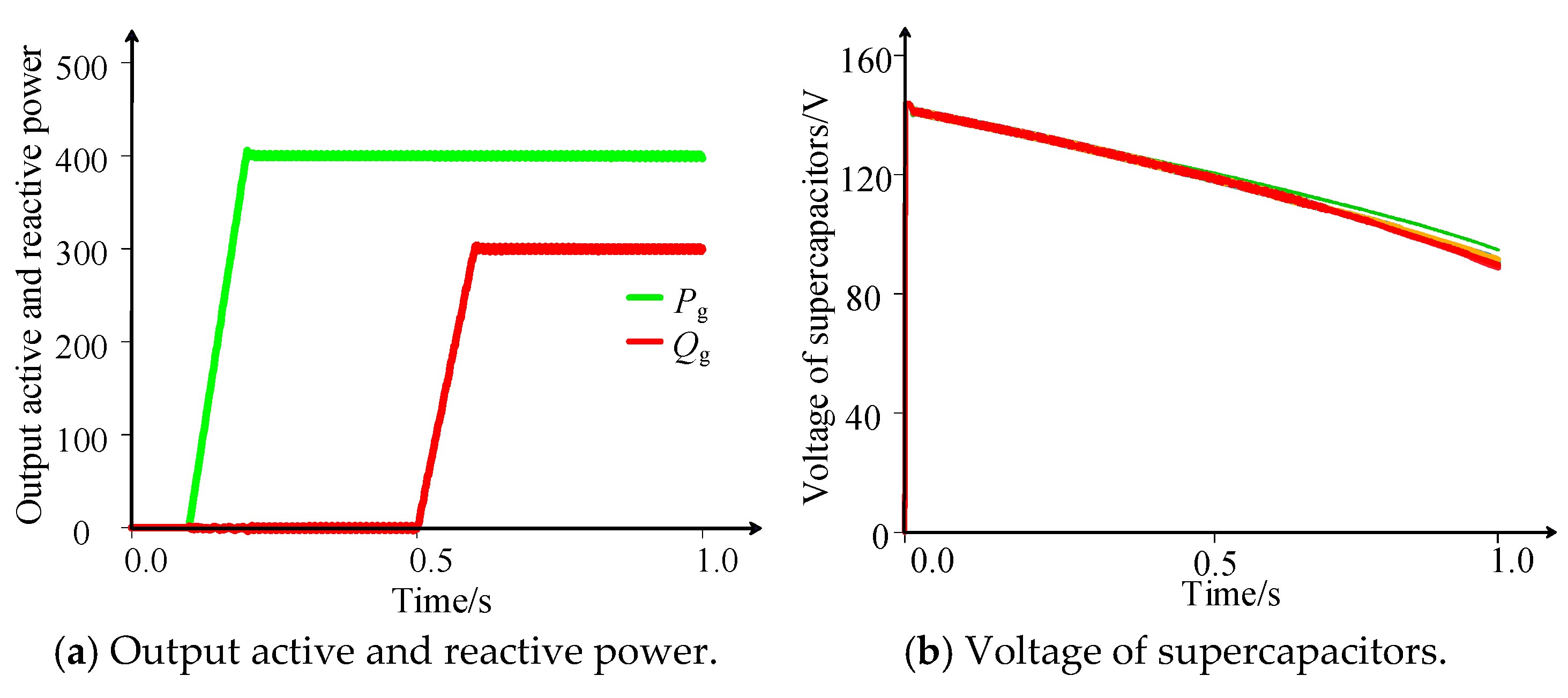
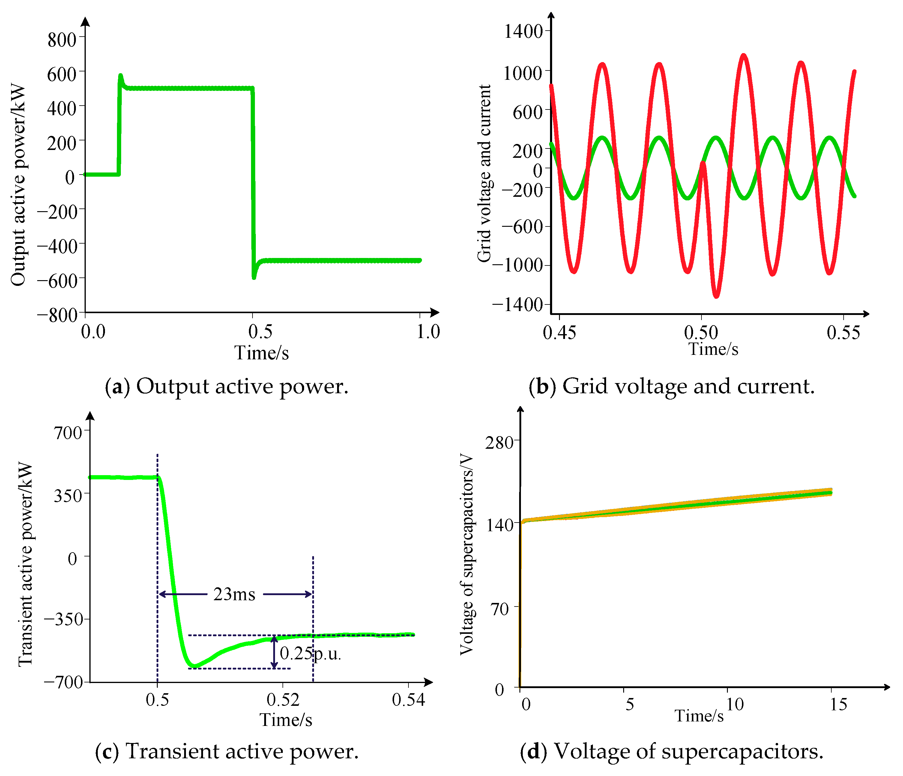
When the active power increases at 0.1 s,
Figure 10a shows that the output active power increases rapidly and enters steady-state operation, during which
Figure 10b shows that the voltages of the supercapacitors remain balanced. Similarly, the same result can be observed when the reactive power increases at 0.5 s, which demonstrates the rapid response of the proposed scheme.
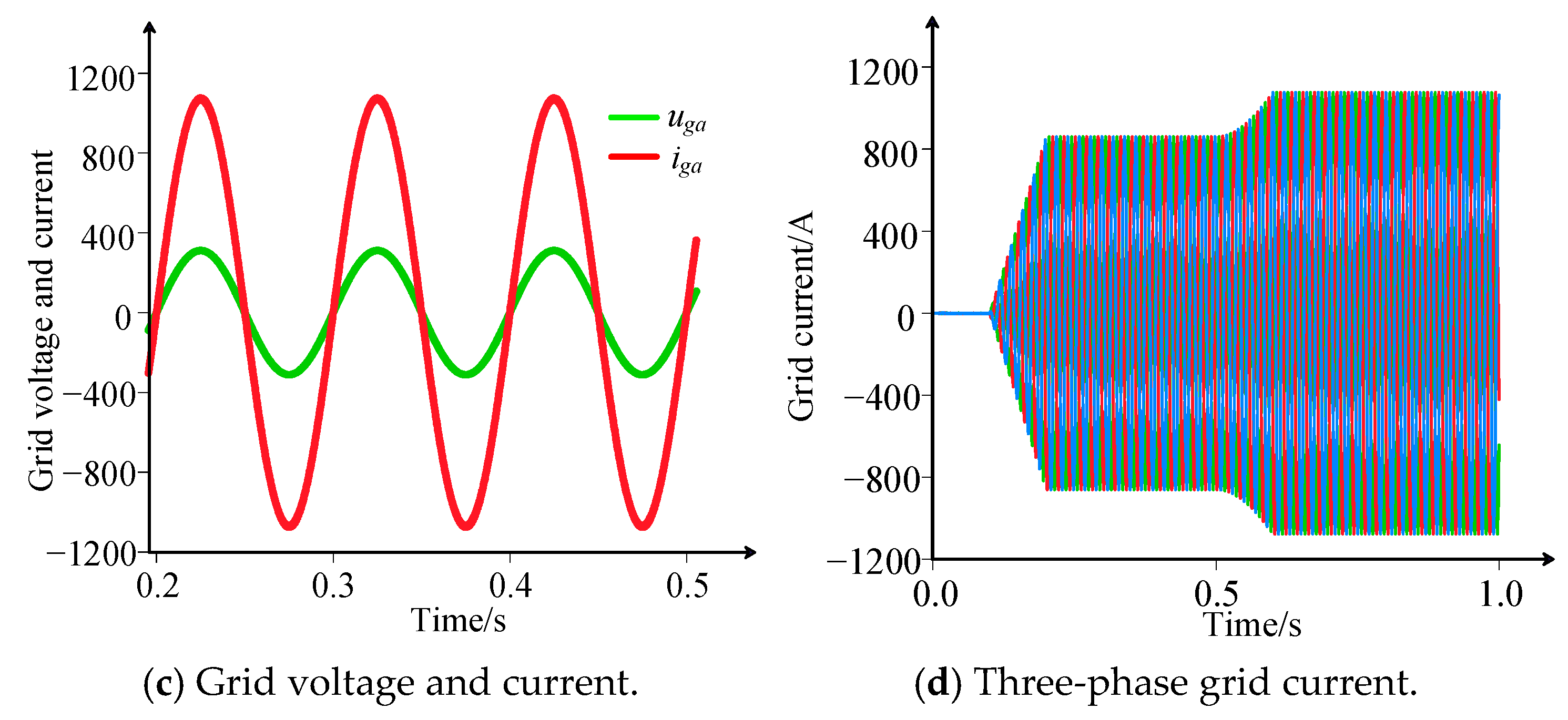
Figure 10c shows that both the single-phase voltage and current waveforms are sinusoidal and in phase with each other, which matches the unit power factor operation of the energy storage converter during the 0.1 to 0.5 s shown in
Figure 10a. Furthermore,
Figure 10d shows that the three-phase current waveforms are symmetrical, and no impact occurs during the transient process, which demonstrates the effectiveness of the power control in the proposed scheme.
6.3. Simulation Results Under Abrupt Power Drop Conditions
As shown in
Figure 11a, the energy storage converter exhibits good transient response and experiences minimal impact when the rated power is suddenly increased from no-load operation, or when the rated forward power is suddenly switched to negative rated power operation. During this process,
Figure 11b shows that the current stabilizes rapidly, and unit power factor operation is also achieved when the power is reversed. Furthermore,
Figure 11c shows that when the active power suddenly changes from positive full load to negative full load operation, the power surge is 0.25 p.u. and the settling time is 23 ms, whose rapid response is evident during sudden full-power changes. Meanwhile,
Figure 11d shows that the voltage difference in all supercapacitors does not exceed 0.07 p.u., so the voltage balancing can also be achieved during negative-rated operation.
6.4. Experimental Validations of the Proposed Method
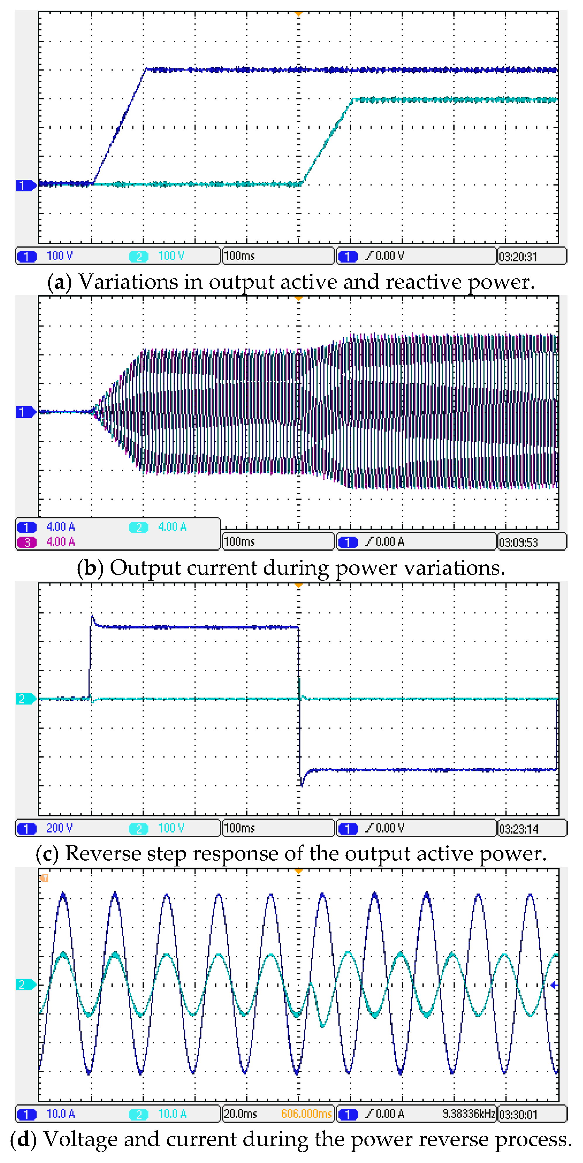
A scaled-down 500 W experiment has been conducted through hardware-in-loop devices and DSP control boards, with the results depicted in
Figure 12. In this figure, the blue and green curves in
Figure 12a and
Figure 12c denote the output active power and output reactive power, respectively, and the blue and green curves in
Figure 12d represent the voltage and current waveforms of phase A, respectively.
Figure 12a shows the dynamic responses of output active and reactive power under step changes. When the active power reference increases from 0 to 500 W and the reactive power reference steps from 0 to 200 Var, the actual power waveforms rise smoothly without observable overshoot, which is consistent with the simulation results in
Figure 10a.
Figure 12b demonstrates that the three-phase output currents remain sinusoidal and well-balanced during the transients, with no visible waveform distortion.
Figure 12c presents the active power reversal from +500 W to −500 W. The transition is rapid, and no significant impact or overshoot is observed, confirming the effective bidirectional regulation capability of the proposed controllable DC bus.
Figure 12d provides a detailed view during the power reversal: before the reversal, the phase current is in phase with the grid voltage (discharging mode); after the reversal, the current becomes exactly anti-phase (charging mode). The phase relationship switches seamlessly, demonstrating robust phase-locked performance. Therefore, the experimental results validate that the proposed energy storage converter based on the controllable DC bus achieves fast dynamic response, stable current quality, and reliable bidirectional power control, thereby confirming its correctness and feasibility.
7. Conclusions
This paper proposes a novel energy storage converter based on the controllable DC bus. The main conclusions are summarized as follows:
(1) The internal resistance loss and bidirectional voltage regulation issues in the cascaded H-bridge-based energy storage converter are analyzed. It is shown that although the internal resistance of energy storage modules in a low-voltage high-power environment does not affect the selection of energy storage products, it causes significant losses, resulting in excessively low device efficiency.
(2) Due to the presence of single-phase double-frequency power fluctuation and the over-modulation during deep charge/discharge state, commonly used bidirectional DC voltage regulation methods are difficult to implement, and the total DC voltage constraint increases, leading to higher energy storage costs.
(3) The proposed topology not only significantly reduces internal resistance losses and improves device efficiency, but also possesses bidirectional DC voltage regulation capability, enabling 33% cost savings and 8.67% maximum loss.
(4) As double-frequency power fluctuations are eliminated, the proposed control offers superior voltage balancing performance and simpler implementation complexity.
Author Contributions
Conceptualization, X.G. and J.Z.; investigation, X.G.; methodology, H.Y.; validation, H.Y. and J.Z.; writing—original draft preparation, H.Y.; writing—review and editing, F.Y. and K.S.; project administration, F.Y.; supervision, K.S. and J.Z. All authors have read and agreed to the published version of the manuscript.
Funding
This research was funded by the 333 Project of Jiangsu Province under Grant (2022) 3-16-854, the 2020 Qing Lan Project of Jiangsu Province, the 2023 University Science and Technology Innovation Team Support Program of Jiangsu Province, the China Postdoctoral Science Foundation under Grant 2025M780480, the Natural Science Foundation of Jiangsu Province under Grant BK20250326, and the Natural Science Foundation of the Jiangsu Higher Education Institutions of China under Grant 25KJB470002.
Data Availability Statement
Data are contained within the article.
Conflicts of Interest
Author J.Z. was employed by the company Wanbang Digital Energy Co., Ltd. The remaining authors declare that the research was conducted in the absence of any commercial or financial relationships that could be construed as a potential conflict of interest.
References
- Sun, B.; Yang, S.; Liu, Z.; Li, T. Analysis on present application of megawatt scale energy storage in frequency regulation and its enlightenment. Autom. Electr. Power Syst. 2017, 41, 8–16+38. [Google Scholar]
- Zhang, M.; Yan, T.; Lai, X.; Chen, J.; Niu, M.; Xu, S. Technology Vision and Route of Energy Storage Under New Power Grid Function Configuration. Power Syst. Technol. 2018, 42, 1370–1377. [Google Scholar]
- Chen, W.; Jiang, X.; Cao, W.; Zhao, J.; Jiang, W.; Jiang, L. A fully modular control strategy for input-series output-parallel (isop) inverter system based on positive output-voltage-amplitude gradient. IEEE Trans. Power Electron. 2018, 33, 2878–2887. [Google Scholar] [CrossRef] [Scilit]
- Xu, J.; Chen, Z.; Xia, J.; Xiang, J.; Wang, T. Research on multi-target power quality control of parallel modular cascaded super-capacitors. J. Power Supply 2019, 18, 157–164. [Google Scholar]
- Xiong, L.; Gui, Y.; Liu, H.; Gong, J. Control strategy of a cascaded inverter for grid-connected photovoltaic system with supercapacitor. Power Syst. Prot. Control 2019, 47, 108–114. [Google Scholar]
- Maharjan, L.; Inoue, S.; Akagi, H. A transformerless energy storage system based on a cascade multilevel pwm converter with star configuration. IEEE Trans. Ind. Appl. 2008, 44, 1621–1630. [Google Scholar] [CrossRef] [Scilit]
- Bi, K.; Sun, L.; An, Q.; Duan, J. Active soc balancing control strategy for modular multilevel super capacitor energy storage system. IEEE Trans. Power Electron. 2019, 34, 4981–4992. [Google Scholar] [CrossRef] [Scilit]
- Jiang, W.; Huang, L.; Zhang, L.; Zhao, H.; Wang, L.; Chen, W. Control of active power exchange with auxiliary power loop in a single-phase cascaded multilevel converter-based energy storage system. IEEE Trans. Power Electron. 2017, 32, 1518–1532. [Google Scholar] [CrossRef] [Scilit]
- Wu, L.; Tu, C.-C.; Jiang, F.; Guo, Q.; Liu, Z. Characteristic analysis of carrier phase-shifted SPWM output voltage of cascaded h-bridge converters. Power Syst. Technol. 2016, 40, 2155–2161. [Google Scholar]
- Miao, Q. Hybrid Cascade Power Conversion System Based on Battery Energy Storage. Master’s Thesis, Beijing Jiaotong University, Beijing, China, 2014. [Google Scholar]
- Gao, Z.; Lu, Q. A hybrid cascaded multilevel converter based on three-level cells for battery energy management applied in electric vehicles. IEEE Trans. Power Electron. 2019, 34, 7326–7349. [Google Scholar] [CrossRef] [Scilit]
- Siwakoti, Y.P. A new six-switch five-level boost-active neutral point clamped (5L-Boost-ANPC) inverter. In Proceedings of the 2018 IEEE Applied Power Electronics Conference and Exposition (APEC), San Antonio, TX, USA, 4–8 March 2018; pp. 2424–2430. [Google Scholar]
- Bi, K.; An, Q.; Duan, J.; Fan, S.; Sun, L. Self-balancing control strategy for super capacitor energy storage system based on cascaded multilevel dc-dc converter. Trans. China Electrotech. Soc. 2018, 33, 1919–1928. [Google Scholar]
- Ma, H.; Lei, J.; Qin, G.; Zhang, Y.; Hao, C. A high-efficiency and low-cost battery energy storage system based on cascaded hybrid h-bridge. In Proceedings of the 2024 IEEE International Conference on Energy Internet (ICEI), Zhuhai, China, 1–3 November 2024; pp. 163–168. [Google Scholar]
- Wang, K.; Shen, Z.; Qu, Y.; Yang, Y.; Tan, W. Topology and control of current-fed quadruple active bridge dc–dc converters for smart transformers with integrated battery energy storage systems. Energies 2025, 18, 5381. [Google Scholar] [CrossRef] [Scilit]
- Kim, M.; Ko, Y. Novel overmodulation strategy for unequal power sharing in a cascaded h-bridge converter. J. Power Electron. 2026, 26, 482–493. [Google Scholar] [CrossRef] [Scilit]
- Poblete, P.; Cuzmar, R.H.; Aguilera, R.P.; Pereda, J.; Alcaide, A.M.; Lu, D.D.-C.; Siwakoti, Y.P.; Konstantinou, G. Dual-stage mpc for soc balancing in second-life battery energy storage systems based on delta-connected cascaded h-bridge converters. IEEE Trans. Power Electron. 2025, 40, 500–515. [Google Scholar] [CrossRef] [Scilit]
- Rocabert, J.; Capó-Misut, R.; Muñoz-Aguilar, R.S.; Candela, J.I.; Rodriguez, P. Control of energy storage system integrating electrochemical batteries and supercapacitors for grid-connected applications. IEEE Trans. Ind. Appl. 2019, 55, 1853–1862. [Google Scholar] [CrossRef] [Scilit]
- Yan, Y. Phase-shift-controlled bidirectional DC converter. In Bidirectional DC Converter; Jiangsu Science and Technology Press: Nanjing, China, 2004; pp. 159–165. [Google Scholar]
- Zhao, B.; Song, Q.; Liu, W. Power characterization of isolated bidirectional dual-active-bridge dc–dc converter with dual-phase-shift control. IEEE Trans. Power Electron. 2012, 27, 4172–4176. [Google Scholar] [CrossRef] [Scilit]
- Fu, W. Research on Pulse Width Modulation and Application for Multilevel Z-Source Inverter. Master’s Thesis, China University of Mining and Technology, Xuzhou, China, 2015. [Google Scholar]
- Mukherjee, N.; Strickland, D. Control of second-life hybrid battery energy storage system based on modular boost-multilevel buck converter. IEEE Trans. Ind. Electron. 2015, 62, 1034–1046. [Google Scholar] [CrossRef] [Scilit]
- Liu, Z.; Liu, Z.; Li, C.; Fu, C. Improved voltage balancing method based on MMC nearest level modulation. Electr. Meas. Instrum. 2017, 54, 87–93. [Google Scholar]
| Disclaimer/Publisher’s Note: The statements, opinions and data contained in all publications are solely those of the individual author(s) and contributor(s) and not of MDPI and/or the editor(s). MDPI and/or the editor(s) disclaim responsibility for any injury to people or property resulting from any ideas, methods, instructions or products referred to in the content. |