


Abstract
A large number of grid-connected inverters have been connected to distribution networks and can be used to mitigate harmonics at the system level. Deploying distributed power electronic devices for harmonic mitigation is a cost-effective solution for distribution networks. However, existing coordination methods typically depend on highly reliable, low-latency communications. Communication delays or interruptions can significantly degrade coordination performance and even exacerbate harmonic distortion. This paper presents a hierarchical, coordinated harmonic compensation method for multiple multifunctional grid-tied inverters (MFGTIs). At the primary control level, harmonic domain virtual admittance is incorporated, enabling each device to adaptively inject harmonic compensation currents using only local measurements, maintaining baseline compensation capability when communication is limited or interrupted. At the secondary control level, a distributed model predictive control (DMPC) scheme is derived from the harmonic steady-state equivalent circuit. The virtual admittance parameters are updated iteratively using measurements exchanged only among neighboring nodes, enabling coordinated sharing of compensation currents without requiring global information or frequent harmonic power flow calculations. Case studies demonstrate that the proposed method reduces nodal harmonic voltages under communication constrained conditions while significantly lowering the computational burden.
1. Introduction
With the large-scale integration of renewable energy sources and nonlinear loads, harmonic disturbances occur more frequently and are present at almost every node [1,2,3], which markedly increases the complexity of harmonic mitigation [4]. Consequently, passive or active filters are becoming insufficient to meet the requirements for fast response and system-level coordination in the presence of widely distributed, dynamically varying harmonic sources. It is difficult to identify suitable current detection points for dispersed background harmonics; therefore, local point-to-point harmonic elimination is no longer applicable [5,6,7].
In modern distribution systems, harmonic sources are widely distributed, and their emission levels vary over time. This leads to an increased need for measurement and compensation devices, resulting in high installation costs and additional operational losses, while the equipment’s overall utilization efficiency remains low [8]. A large number of distributed energy resources (DERs), such as photovoltaic and energy storage systems, are connected to distribution networks and can be exploited for harmonic mitigation, since their grid-connected inverters share similar topologies with power control devices [9,10], leading to the concept of the multifunctional grid-tied inverter (MFGTI). To address the complex harmonic distortion in modern distribution systems, coordinated mitigation among multiple devices is essential.
Existing control approaches can be broadly categorized as centralized control [11] or distributed control [12]. Centralized control relies on a central controller that collects network-wide measurement data, computes control setpoints in a unified manner, and dispatches them to individual mitigation devices [13]. To enable coordinated operation among multiple devices, Refs. [14,15] propose a centralized power-sharing mode in which the compensation capacity is allocated based on rated capacities and adjusted by a central coordinator. Beyond capacity allocation, Ref. [16] reports a deployment strategy that places shunt active power filters (SAPFs) near a limited number of nonlinear loads to curb harmonic injection and improve system-level harmonic performance. To achieve optimal suppression of harmonic distortion across the network, Refs. [17,18,19] pursue centralized optimization-based scheduling under network-wide information aggregation. Specifically, Ref. [17] aggregates network-wide harmonic information at a central unit and issues compensation commands for coordinated suppression; Ref. [18] develops a two-level optimization model to centrally and optimally allocate harmonic compensation capacity to each inverter; and Ref. [19] formulates a multi-resource centralized optimization model that combines network-wide harmonic disturbances with distributed energy resource (DER) operating states and minimizes the sum of nodal voltage THD. Further, considering network coupling characteristics, Ref. [20] develops a coordination method based on the relative gain matrix for MFGTIs, which jointly optimizes compensation resource allocation and monitoring node selection under capacity constraints. Despite their effectiveness, centralized strategies can impose considerable computational burden and stringent communication requirements in distribution networks, particularly under high harmonic penetration. Under industrial operating conditions, communication failures may compromise capacity allocation and degrade harmonic mitigation, potentially aggravating harmonic distortion.
Distributed control enables local computation through coordination among multiple control units [21]. Relative to centralized schemes, it typically reduces communication overhead and computational complexity while still delivering satisfactory control performance. Among existing distributed harmonic-mitigation studies, some methods mainly rely on consensus-based coordination, some emphasize distributed optimization, and some combine predictive control with partitioned coordination. For example, Ref. [12] coordinates the sharing of harmonic-mitigation tasks among multiple grid-tied inverters through a distributed consensus strategy, thereby improving both compensation sharing and overall system performance. Ref. [22] also employs cooperative multi-agent coordination and tunes the parameters of a voltage detection active power filter (VDAPF) within a distributed harmonic-mitigation framework. Beyond consensus-based approaches, Ref. [23] formulates APF configuration as a distributed primal-dual subgradient optimization problem, while Ref. [24] introduces a blockchain-based incentive mechanism that enables regional VDAPFs to self-organize for distributed harmonic compensation without a centralized controller. In addition, some studies incorporate predictive coordination into distributed harmonic control. Ref. [25] addresses voltage-distortion mitigation through a partitioned optimization model based on the alternating direction method of multipliers (ADMM). By integrating model predictive control with a rolling correction mechanism, regional autonomy is achieved. Although these studies have demonstrated the effectiveness of distributed coordination, many of them still rely on global reference quantities, iterative consensus updates, or intensive information exchange within each control interval. When communication is interrupted, these iterations may stall, thereby degrading control performance.
In contrast to the above studies, the proposed method does not rely on repeated consensus iterations or network-wide coordination within each control interval. Instead, it combines local harmonic domain virtual admittance control with neighbor-based distributed model predictive control (DMPC) coordination. Within this hierarchical framework, each MFGTI preserves baseline local harmonic-compensation capability using only locally measured PCC harmonic voltages when communication is limited. The secondary layer coordinates multiple MFGTIs through a prediction model derived from the harmonic steady-state equivalent circuit and neighboring node measurements. Based on this model, a receding-horizon optimization is performed to coordinate harmonic mitigation without repeated network-wide harmonic power flow calculations, thereby reducing online computational and communication overhead. The main contributions of this paper are summarized as follows:
- (1)
- A phase tunable virtual admittance in the harmonic domain is introduced to enhance the harmonic compensation capability of MFGTIs. By regulating its phase angle, the phase of the injected harmonic current can be controlled, thereby providing an additional degree of freedom for harmonic suppression. The relationship between the virtual admittance phase angle and the PCC harmonic voltage magnitude is also analyzed.
- (2)
- A hierarchical harmonic compensation framework is proposed to reduce the reliance on highly reliable system-wide communication. At the primary level, virtual admittance control maintains local compensation capability. At the secondary level, the proposed DMPC scheme determines the virtual admittance parameters using only neighboring node information, without requiring global reference quantities or repeated consensus iterations.
- (3)
- A low dimensional predictive optimization model is established for the proposed DMPC scheme. Using the harmonic steady-state equivalent circuit and the neighboring node harmonic voltage information from the previous control interval, the model predicts the harmonic voltage and compensation current in the current interval. This avoids repeated network-wide harmonic power flow calculations and reduces the computational burden.
The remainder of this paper is organized as follows. Section 2 introduces the harmonic domain virtual admittance control principle for the MFGTI. Section 3 presents the DMPC method based on the distribution network’s harmonic steady-state equivalent circuit. Section 4 provides case studies to validate the proposed method. Section 5 concludes the paper and outlines future work.
2. Virtual Admittance-Based Control of MFGTI for Harmonic Compensation
This section introduces a virtual admittance control strategy that compensates for harmonics in MFGTIs by enabling the adaptive injection of harmonic currents based on the harmonic voltage at the point of common coupling (PCC). It then derives the voltage suppression mechanism of the virtual admittance using a harmonic equivalent circuit, laying the groundwork for coordinating multiple MFGTIs.
2.1. Virtual Admittance-Based Control Strategy for Harmonic Compensation Using MFGTI
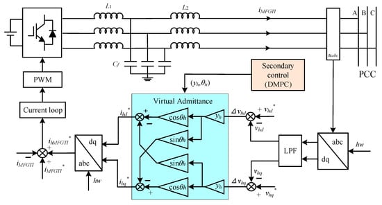
When the MFGTI participates in harmonic compensation, its primary control structure is shown in Figure 1. The primary control loop operates as follows. First, the three-phase PCC voltage is measured and transformed into the harmonic synchronous dq frame at the selected harmonic frequency, so that the target harmonic components can be represented by the DC quantities vhd and vhq. These components are then filtered by a low-pass filter to suppress non-target frequency components and transient disturbances. Based on the filtered harmonic voltage, the virtual admittance block generates the harmonic current reference according to the admittance magnitude and phase angle provided by the secondary controller. Finally, the reference harmonic current is tracked by the inner current loop through PWM, so that the MFGTI injects the required harmonic compensation current into the grid.
Figure 1.
Primary control scheme of the virtual admittance for harmonic compensation in MFGTI.
Here, L1, L2, and Cf denote the inverter-side inductance, grid-side inductance, and filter capacitance of the LCL filter, respectively. The variable iMFGTI denotes the three-phase current injected into the grid, and uabc denotes the three-phase PCC voltage. hω is the angular frequency of the hth harmonic. The quantities vhd and vhq are the d- and q-axis components of the hth harmonic voltage, and vhd* and vhq* are their corresponding reference values. Similarly, and denote the d- and q-axis reference components of the hth harmonic current. yh and θh are the magnitude and phase angle of the hth virtual admittance. ihMFGTI* is the three-phase reference harmonic compensation current of the MFGTI, and iMFGTI* is the reference value for the MFGTI’s fundamental current. The secondary control uses the proposed DMPC scheme, whose operating principle will be detailed in the next section.
The three-phase voltage at the PCC, vabc, is measured and transformed into the synchronous rotating dq frame at the target harmonic angular frequency, hω, to obtain the harmonic voltage components, vhd and vhq. To reduce non-target frequency components and transient disturbances, a first-order low-pass filter is used to isolate the steady-state harmonic components. The harmonic compensation current reference is then generated based on the virtual admittance’s magnitude and phase angle, which are calculated by the secondary control system. The virtual admittance for the hth harmonic is defined as:
In the synchronous reference frame, the admittance Yh is represented as a complex quantity, yh∠θh. Here, yh is the magnitude of the admittance, which controls the amplitude of the harmonic compensation current, and θh is the phase angle, which determines the phase of the current.
To suppress harmonic voltage with a zero reference, the harmonic voltage regulation term is defined as Δvh = −[vhd, vhq]T. Accordingly, the compensation current command for the hth harmonic can be written as:
Substituting Δvh = −[vhd, vhq]T into (2) and expanding the matrix multiplication yields the component-wise form in (3).
The harmonic compensation current command is passed to the inner current loop, which produces the modulation signal, which is then applied to the inverter’s power stage via PWM, resulting in an AC grid current that includes the harmonic compensation components.
Once the virtual admittance parameters are configured, each unit injects harmonic compensation currents based on local PCC harmonic voltage measurements, ensuring consistent compensation performance even in the absence of communication or under impaired communication conditions. Additionally, device virtual admittance settings enable coordinated sharing of harmonic compensation efforts across multiple units.
2.2. Mechanism of Harmonic Voltage Suppression via Harmonic Domain Virtual Admittance
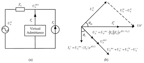
Based on the harmonic equivalent circuit in Figure 2a, this paper analyzes the role of the MFGTI harmonic domain virtual admittance in harmonic suppression. The corresponding phasor diagram in Figure 2b further illustrates how the phase angle of the virtual admittance affects the direction of the injected compensation current and the resulting PCC harmonic voltage.
Figure 2.
(a) Equivalent circuit of harmonics under MFGTI integration; (b) Phasor diagram of harmonic voltages and currents.
At the harmonic frequency, the MFGTI can be modeled using the equivalent circuit shown in Figure 2, where and are the background and PCC harmonic voltages, ZL is the line impedance, is the compensation current injected by the MFGTI, and is the harmonic source current. Applying Kirchhoff’s voltage law (KVL), we obtain:
Substituting = Yh into (4) gives
which leads to the PCC harmonic voltage expression in (6):
Given the background harmonic voltage, the harmonic source current, and the line impedance, the magnitude of the PCC harmonic voltage, ||, is primarily influenced by |1 + YhZL|. To better understand its impact, Yh and ZL are expressed in polar form, and their product can be written as:
where ϕh = θY + θZL is the composite phase angle.
By writing YhZL = |YhZL| and using the identity |1 + a|2 = 1+|a|2 + 2Re(a), the magnitude term can be expanded as in (8).
When ϕh = 0, cos(ϕh) reaches its maximum value, causing Equation (8) to attain its peak value, which results in the minimum harmonic voltage at the PCC. Thus, the optimal control condition is given by:
Figure 2b depicts the phasor relationships among the harmonic voltages and currents discussed above. The harmonic voltage associated with , together with , constitutes a vector sum that is equal to the vector difference between and the harmonic voltage corresponding to . For identical admittance magnitudes, becomes collinear with when θY = −θZL, in which case the magnitude of || is minimized.
Thus, by fixing |Yh| and adjusting the phase angle of the virtual admittance to meet the optimal phase condition for the injected compensation current, the PCC harmonic voltage can be further reduced. In contrast to tuning only the conductance, the proposed complex-admittance tuning provides an additional degree of freedom, thereby enhancing harmonic compensation.
3. DMPC for Coordinated Operation of Multiple MFGTIs
To reduce communication and computational overhead, this paper proposes a DMPC scheme to coordinate multiple MFGTIs by dynamically adjusting their harmonic domain virtual admittance setpoints.
3.1. Harmonic Steady-State Equivalent Circuit of Distribution Networks
To develop a virtual harmonic admittance based on the DMPC scheme, the distribution network’s harmonic steady-state model is formulated in the synchronous reference frame. By applying a reference transformation at the harmonic frequency hω, the harmonic voltages and currents are converted into DC quantities. As a result, the network is represented by a harmonic steady-state equivalent circuit.
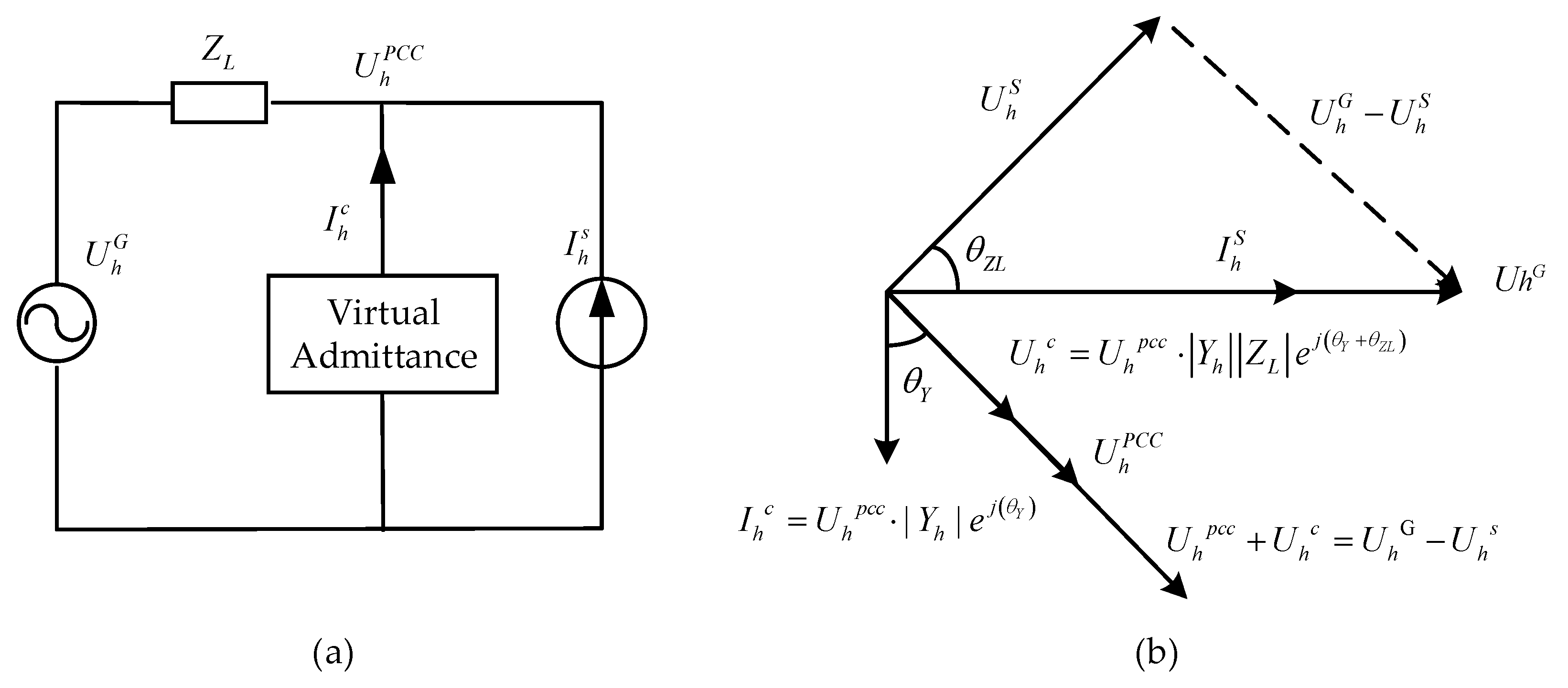
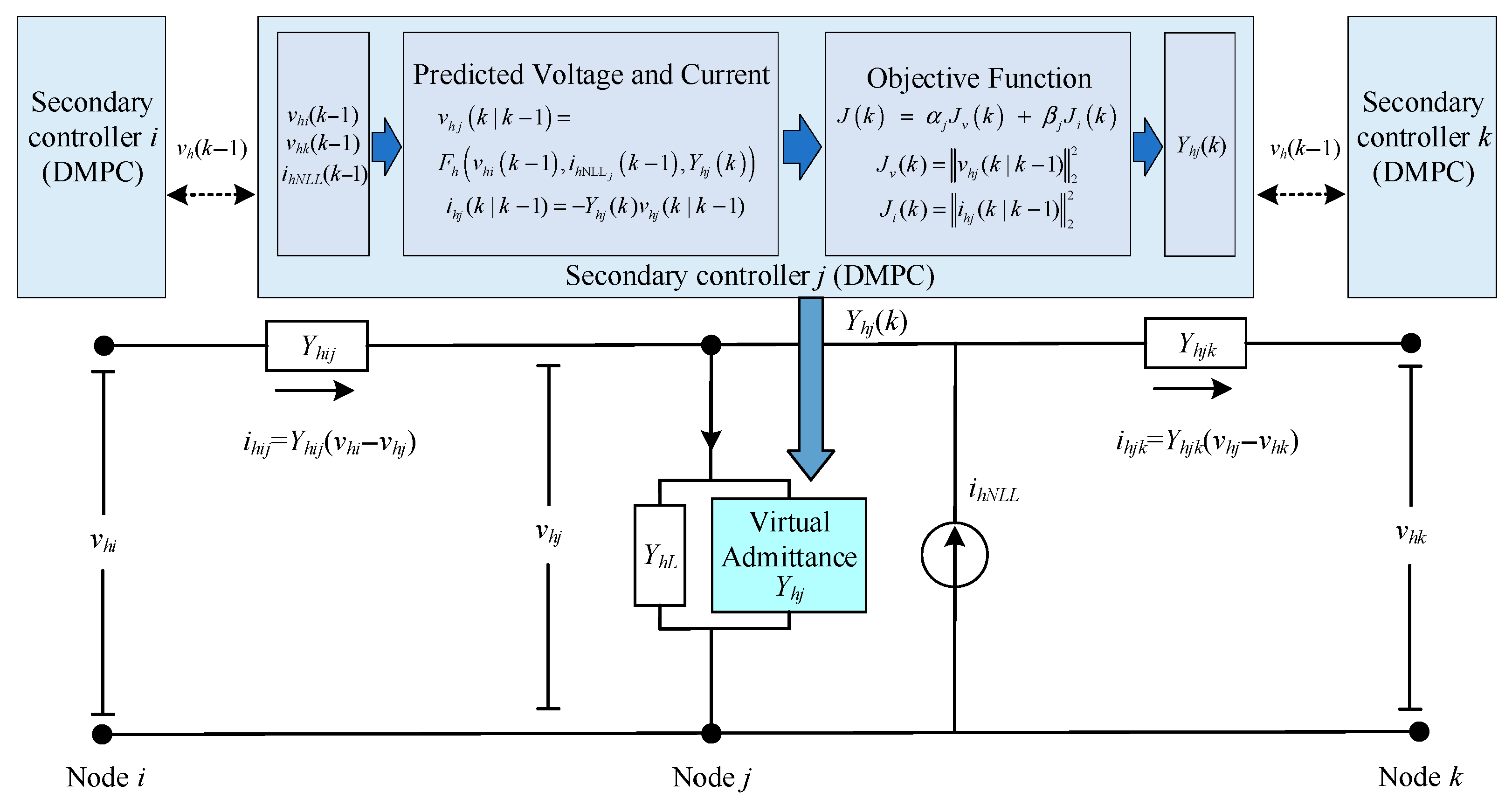
As illustrated in Figure 3, the distribution network at harmonic order h is represented by a Norton-equivalent network, with nodal self-admittances and mutual admittances between nodes. In the following formulation, harmonic voltages and currents are treated as 2 × 1 vectors, while admittance quantities are treated as 2 × 2 matrices. The harmonic voltage and current at node j for the hth harmonic are denoted by:
Figure 3.
Harmonic steady-state equivalent circuit of a distribution network.
At the hth harmonic frequency, the self-admittance YhL and the mutual admittance matrix Yhij between nodes i and j are given by:
where GhL and BhL are the conductance and susceptance of node j at the hth harmonic, respectively, Ghij and Bhij are the conductance and susceptance between nodes i and j at the hth harmonic. The virtual admittance of the MFGTI at node j, Yh, is given by (1) and is determined by the parameters yh and θh.
The branch current at the hth harmonic between nodes i and j is given by:
where ihij = [ihijd, ihijq]T is the harmonic current vector flowing from node i to node j.
Let Kj denote the set of neighboring nodes of node j. By applying Kirchhoff’s Current Law (KCL) and considering the network topology along with the harmonic current injection from the MFGTI, the current at any node j is given by:
where ihNLLj is the harmonic current injected at node j by the nonlinear load.
Rearranging (13) by collecting the terms associated with vhj gives the nodal harmonic voltage expression in (14).
where “−1” is the matrix inverse.
3.2. Predictive Model
Performing a network-wide harmonic power flow calculation at every sampling instant would incur significant communication and computational overhead. Because the harmonic admittances of lines and loads remain approximately constant between adjacent sampling intervals, this paper proposes a DMPC that relies on neighborhood measurements. At the kth control period, the harmonic voltages of neighboring nodes and the nonlinear load harmonic current at node j are predicted using the measurements taken at the end of the previous period, i.e., vhi(k − 1) and ihNLLj(k − 1), respectively. Substituting these held measurements into (14), while keeping the current-interval harmonic domain virtual admittance Yhj(k) as the control input, yields the predicted hth harmonic voltage at node j, as given in (15).
Thus, the relationship for predicting the harmonic voltage can be written as:
Given the slow variation in harmonic voltages and loads over multiple fundamental cycles, this paper adopts a DMPC structure with a prediction horizon Np = 1 and a control horizon Nc = 1.
3.3. Objective Function and Constraints
3.3.1. Objective Function
Based on the above prediction model, a multi-objective optimization function is constructed to account for both harmonic voltage suppression and compensation current allocation. In the kth control cycle, the harmonic voltage at node j is denoted as vhj(k), and the corresponding objective function for harmonic voltage suppression is formulated as:
To promote a balanced sharing of the harmonic compensation effort among participating units, the objective function includes a weighted norm of the injected harmonic current. The compensation current injected by the MFGTI at node j for the hth harmonic is expressed as:
With this definition, the harmonic compensation current index is written as:
Therefore, the local DMPC objective is constructed from two terms: the predicted harmonic-voltage magnitude at the controlled node and the predicted compensation-current effort of the local MFGTI. The optimization in (20) thus explicitly balances voltage suppression against converter current usage. The overall objective is defined as a weighted sum of the two terms:
where αj and βj are weighting coefficients chosen according to the capacity and operating priority of each MFGTI. This weighting strategy enforces a coordinated trade-off between suppressing the hth harmonic voltage and allocating the compensation effort, thereby preventing sustained overloading of any single MFGTI.
3.3.2. Harmonic Current Constraints
To keep each MFGTI within its safe operating limits during harmonic compensation, the injected hth harmonic current is subject to a magnitude constraint. Let be the maximum allowable current magnitude of the MFGTI at node j. The constraint is given by:
This constraint does not bound the d- and q-axis components separately; it limits only the magnitude of the resultant harmonic current. As a result, each MFGTI remains within its safe operating range even in the presence of local harmonic variations.
3.4. DMPC Framework
At each control cycle, the neighboring node measurements from the previous cycle are treated as known quantities, so that the network states are decoupled from the decision variables. Under this approximation, the harmonic network equations can be reformulated as an optimization problem in the virtual admittance magnitude yh and phase angle θh. Since only the local virtual admittance parameters are updated online, the resulting problem remains low-dimensional and suitable for efficient implementation at each control interval.
To compensate for the approximation introduced by using held measurements, the proposed method adopts a receding-horizon update mechanism. At interval k, the optimization is solved using the measurements acquired at the end of interval k − 1, and the updated virtual admittance parameters are then applied to the system. New measurements collected in the next interval are subsequently used for re-optimization. By repeatedly executing this closed-loop procedure, the operating point is iteratively corrected from one control interval to the next, so that the harmonic compensation performance can be progressively improved under slowly varying harmonic conditions.
The proposed framework is also well-suited for distributed implementation. Each MFGTI relies only on local measurements and measurements from neighboring nodes, without requiring a centralized coordinator to collect network-wide information. In this way, the harmonic coupling among adjacent nodes can still be reflected in the local optimization problem, while the communication burden is significantly reduced compared with methods that depend on repeated network-wide data exchange or repeated harmonic power flow calculations.
To further clarify the practical properties of the proposed DMPC formulation, feasibility, computational burden, and convergence are briefly discussed here. Feasibility is supported by the harmonic-current magnitude constraint in (21) and by restricting the virtual admittance variables to bounded admissible ranges. If the optimization at interval k becomes infeasible due to measurement disturbance or prediction mismatch, the controller retains the previously feasible admittance setting, i.e., Yh(k) = Yh(k − 1). The online computational burden is therefore dominated by a local low-dimensional optimization rather than repeated network-wide harmonic power flow calculations. Regarding convergence, this work does not claim a formal global stability proof for the full nonlinear closed-loop system. Instead, under practical conditions including a stable inner current-control loop, bounded optimization variables and compensation currents, and relatively slow variation in harmonic quantities between adjacent control intervals, the receding-horizon update acts as an iterative correction mechanism, and the simulated trajectories evolve toward a steady operating regime in the studied cases.
3.5. DMPC Procedure
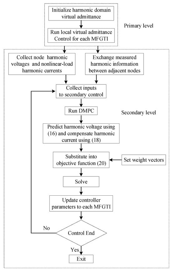
The proposed control strategy updates the virtual admittance parameters for harmonic compensation using measurements collected periodically at each node. The DMPC flowchart is shown in Figure 4.
Figure 4.
DMPC Flowchart.
Let the magnitude and phase angle of the virtual admittance Yh for each MFGTI be the optimization variables, and define xh = [yh, θh]T. The DMPC procedure is then formulated as follows:
Step 1: Set the DMPC period and the maximum allowable harmonic compensation current. Specify the admissible range of the virtual admittance parameters and choose the weighting coefficients αj and βj in the objective function.
Step 2: Initialize and assign the harmonic domain virtual admittance parameters for each MFGTI as xh0 = [yh0, θh0]T.
Step 3: At the end of control cycle k − 1, measure the nodal harmonic voltage vector vh(k − 1) and the nonlinear-load harmonic current ihNLL(k − 1). Exchange the measured harmonic voltage information with adjacent nodes.
Step 4: Substitute the neighbor measurements from cycle k − 1 into (16) to predict the harmonic voltage for cycle k and compute the predicted harmonic compensation current according to (18).
Step 5: Substitute the predicted harmonic voltage and compensation current into the objective function (20), and formulate the resulting local constrained optimization problem subject to all constraints.
Step 6: Each MFGTI solves its local optimization problem numerically to obtain the updated virtual admittance parameters xh*(k). If the problem becomes infeasible, the previously feasible admittance setting is retained for the current interval.
Step 7: Dispatch the updated xh*(k) to each MFGTI to update its local virtual harmonic admittance. If the control task is not completed, return to Step 3 for the next cycle; otherwise, exit.
From a practical implementation perspective, measurement noise may introduce prediction errors in the DMPC update, but its influence is limited by the receding-horizon correction mechanism, bounded parameter ranges, and the fallback strategy. Moreover, because each MFGTI solves only a local low-dimensional optimization problem at each control interval, the real-time computational burden remains much lower than that of repeated network-wide harmonic power flow calculations.
4. Results and Analysis
To validate the proposed method, two case studies are carried out in MATLAB/Simulink R2024a: (i) a grid-connected MFGTI under harmonic domain virtual admittance control, and (ii) a distribution network with multiple MFGTIs under DMPC.
4.1. Simulation Results for a Grid-Connected MFGTI System Under Harmonic Domain Virtual Admittance Control
A grid-connected MFGTI system is modeled to evaluate the proposed virtual admittance control for harmonic mitigation. The seventh-order harmonic (h = 7) is selected as a representative case. For comparison, a VDAPF-based baseline that tunes only the virtual conductance is considered. Both methods are implemented on the same converter plant and evaluated under the same grid impedance, harmonic disturbance, and connection instant. The VDAPF baseline is restricted to conductance tuning, whereas the proposed method uses both admittance magnitude and phase angle, so the comparison is intended to highlight the benefit of the additional phase angle tuning degree of freedom under the same operating conditions. The key simulation parameters are summarized in Table 1.
Table 1.
Key Parameters of the MFGTI Virtual Admittance Grid-Connected System.
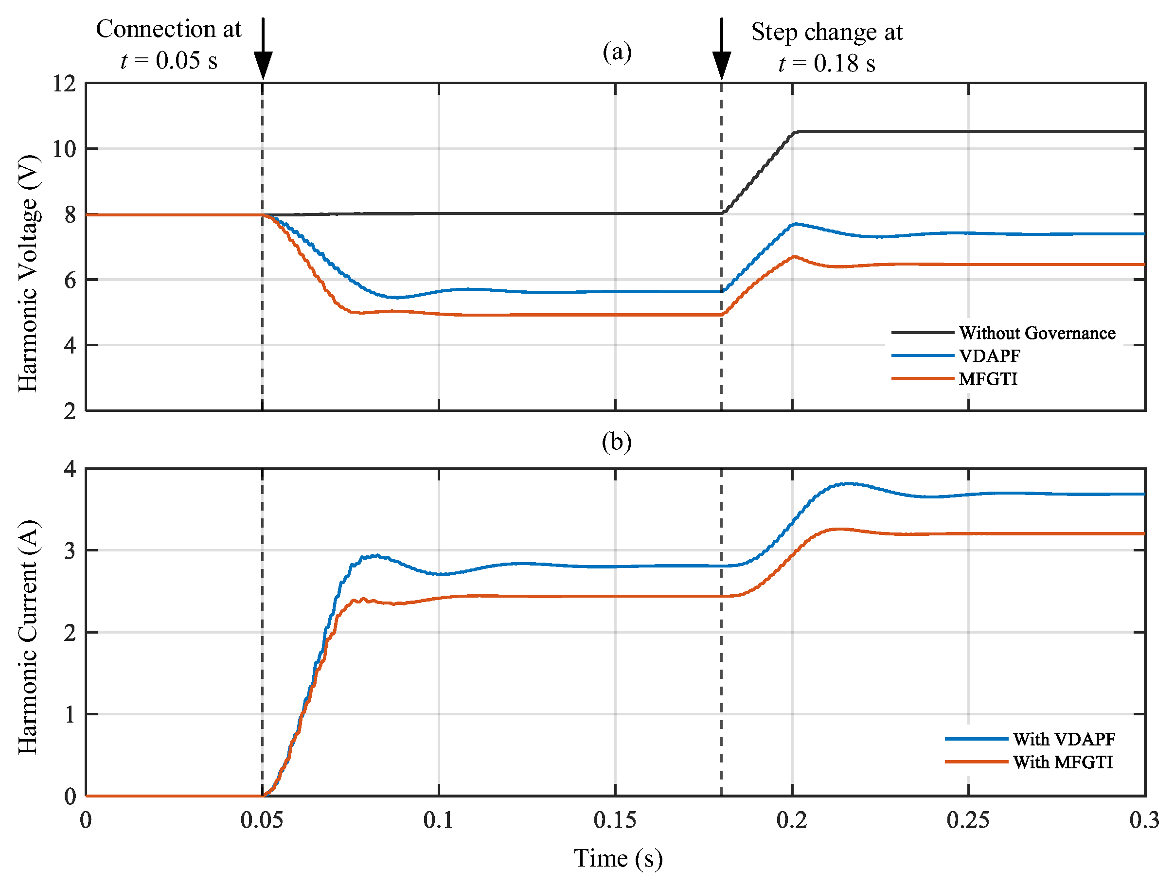
To emulate upstream harmonic penetration, a 7th harmonic background voltage source with an amplitude of 3 V and a ±10% variation is superimposed in the simulation. The injected 7th harmonic current is initialized at 4 A (±10%) and is stepped to 6 A at t = 0.18 s to emulate time-varying harmonic conditions.
For the base case in Figure 5, the virtual admittance phase angle is selected according to the impedance-alignment condition derived in Section 2.2, yielding θh = −1.071 rad, while the admittance magnitude is set to yh = 0.5 as a representative compromise between harmonic voltage suppression and compensation-current requirement. The VDAPF baseline uses conductance tuning with the same nominal magnitude. Both methods are implemented on the same converter plant and evaluated under the same grid impedance and harmonic source conditions, and both are connected to the grid at t = 0.05 s.
Figure 5.
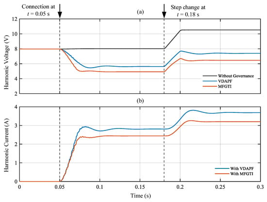
Simulation results of the grid-connected MFGTI system: (a) 7th harmonic voltage magnitude before and after compensation; (b) compensating harmonic currents of the VDAPF and MFGTI.
Figure 5a compares the 7th harmonic PCC voltage under the uncompensated case, the VDAPF case, and the proposed MFGTI case. As marked in the figure, both the MFGTI and the VDAPF are connected at t = 0.05 s, after which the harmonic voltage decreases significantly in both compensated cases. The proposed MFGTI achieves a lower steady-state voltage than the VDAPF, reducing the voltage magnitude to about 4.8 V, compared with about 5.7 V for the VDAPF. The harmonic current step change is applied at t = 0.18 s, as also indicated in Figure 5a. After this disturbance, the proposed method still maintains a lower steady-state harmonic voltage with smaller fluctuations. Under the same nominal tuning magnitude, the lower steady-state voltage of the proposed MFGTI reflects the benefit of the additional phase angle tuning capability of the virtual admittance.
To further relate Figure 5a to the theoretical analysis, a sample calculation is given for the 7th harmonic case. From Table 1, the harmonic line impedance is ZL = Rg + jωhLg = 0.6 + j1.10 Ω, with |ZL| = 1.253 Ω and ∠ZL = 1.071 rad. Before compensation, with a background harmonic voltage of 3 V and a harmonic source current of 4 A, according to (6), the PCC harmonic voltage is approximately 8.01 V, which explains the initial level in Figure 5a. For the proposed MFGTI, the virtual admittance phase angle is selected according to (9), i.e., θh = −θZL = −1.071 rad. With yh = 0.5, the corresponding steady-state PCC harmonic voltage is approximately 4.93 V. By comparison, for the VDAPF case with the same nominal magnitude, the corresponding value is 5.73 V. These calculated values are in good agreement with the simulated steady-state voltages in Figure 5a and also explain the lower compensation current of the proposed method shown in Figure 5b.
Figure 5b shows the injected 7th harmonic compensation currents of the proposed MFGTI and the VDAPF. As marked in the figure, both devices are connected at t = 0.05 s, at which point the compensation currents rise rapidly from zero. The harmonic current step change occurs at t = 0.18 s and causes a further increase in the injected compensation current for both methods. Over the entire compensation interval, the proposed MFGTI requires a smaller current magnitude than the VDAPF. Moreover, its transient response is smoother both at the connection instant and after the step change, with less abrupt current variation. Combined with the voltage results in Figure 5a, these observations show that the proposed method achieves improved harmonic suppression with a lower compensation current requirement.
To illustrate the effect of the virtual admittance setting, Table 2 summarizes the steady-state and transient responses under representative parameter combinations. Here, M1–M4 correspond to magnitude variation with θh = θh*, whereas P1–P5 correspond to phase angle variation for yh = 0.5.
Table 2.
Effect of virtual admittance settings on harmonic-compensation performance.
Table 2 shows that increasing yh improves harmonic voltage suppression but also increases the compensation current. For a fixed magnitude, the best suppression is achieved when θh remains close to the condition derived in Section 2.2. These results indicate that the base-case setting adopted in Figure 5 provides a balanced performance in the studied case.
4.2. DMPC of Multiple MFGTIs
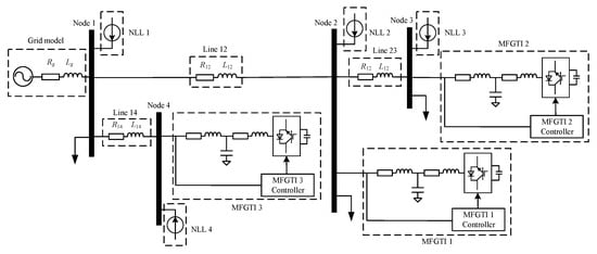
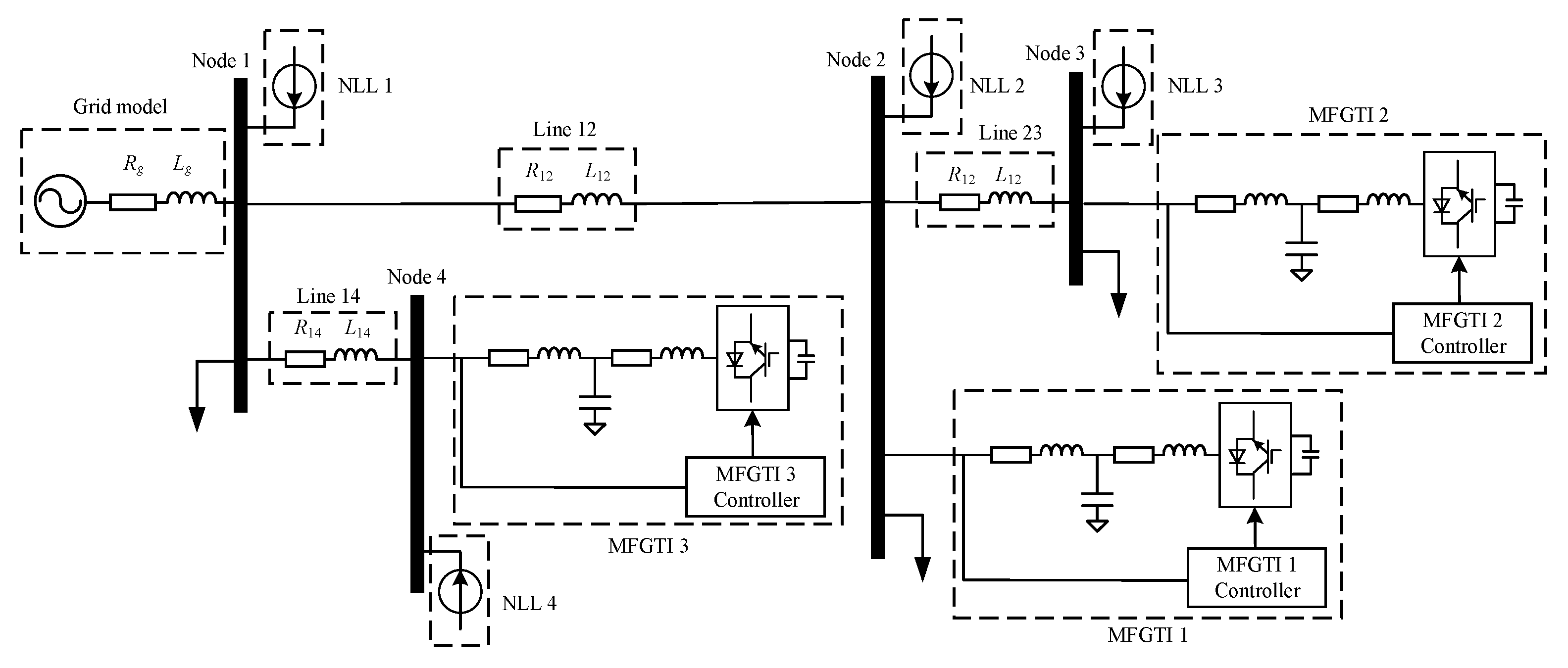
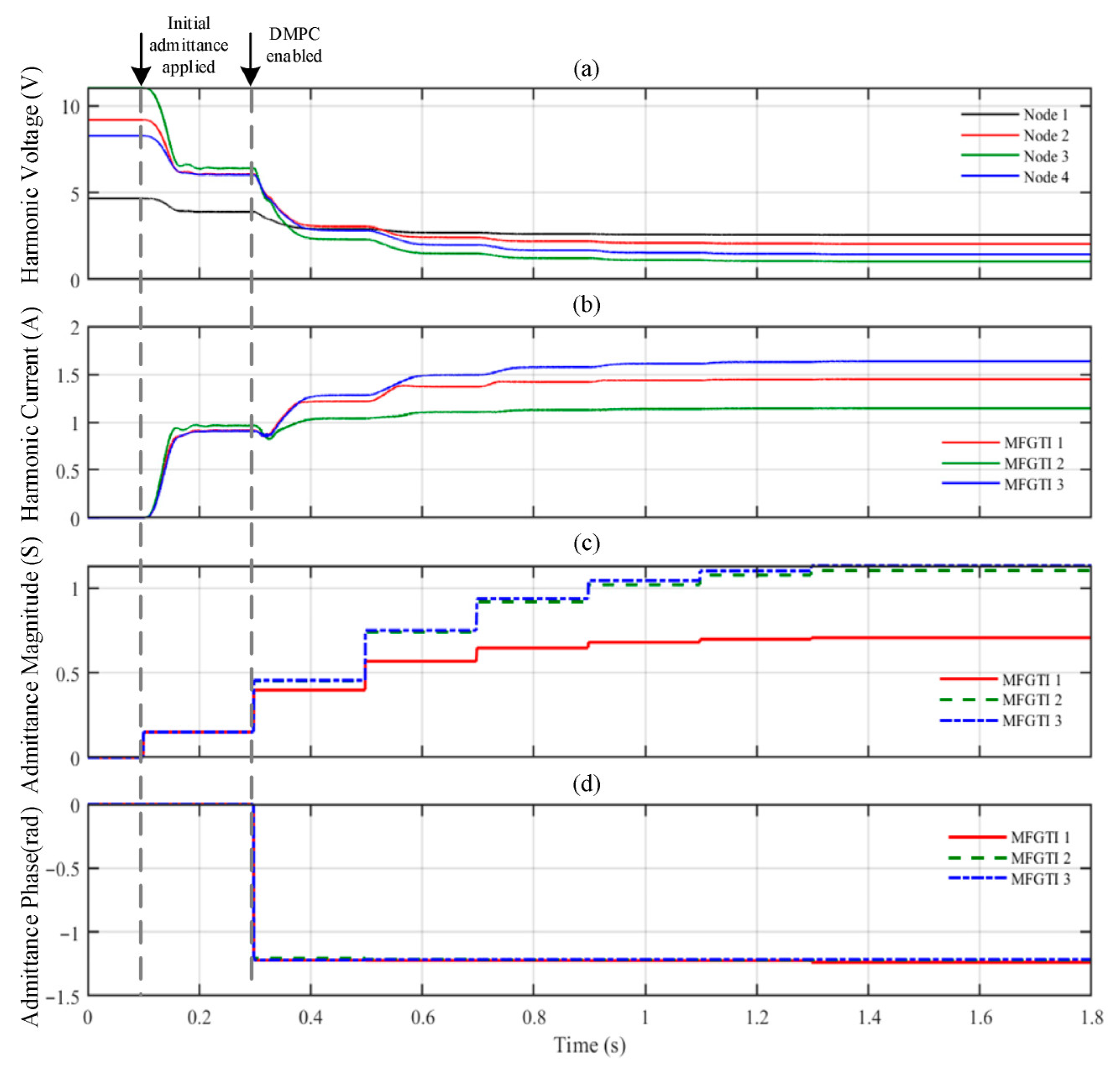
To evaluate the proposed DMPC scheme for coordinated harmonic mitigation with multiple MFGTIs, a typical radial distribution network is considered, as shown in Figure 6. A medium voltage feeder supplies the network. Three MFGTIs with harmonic domain virtual admittance control are connected to different buses, forming a distributed compensation architecture. In the simulations, a 7th harmonic current source and a 7th harmonic voltage source are superimposed to emulate nonlinear load harmonic injection and upstream harmonic penetration, respectively. To reflect the dependence of harmonic magnitudes on the fundamental current and time-varying operating conditions, the harmonic injections at each bus are randomly generated within 5–10% of the corresponding fundamental current magnitude. The line parameters, bus loads, and harmonic source settings are summarized in Table 3.
Figure 6.
Simulation architecture of the distribution network with multiple MFGTIs.
Table 3.
Distribution network parameters.
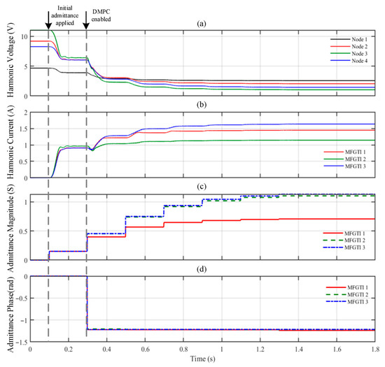
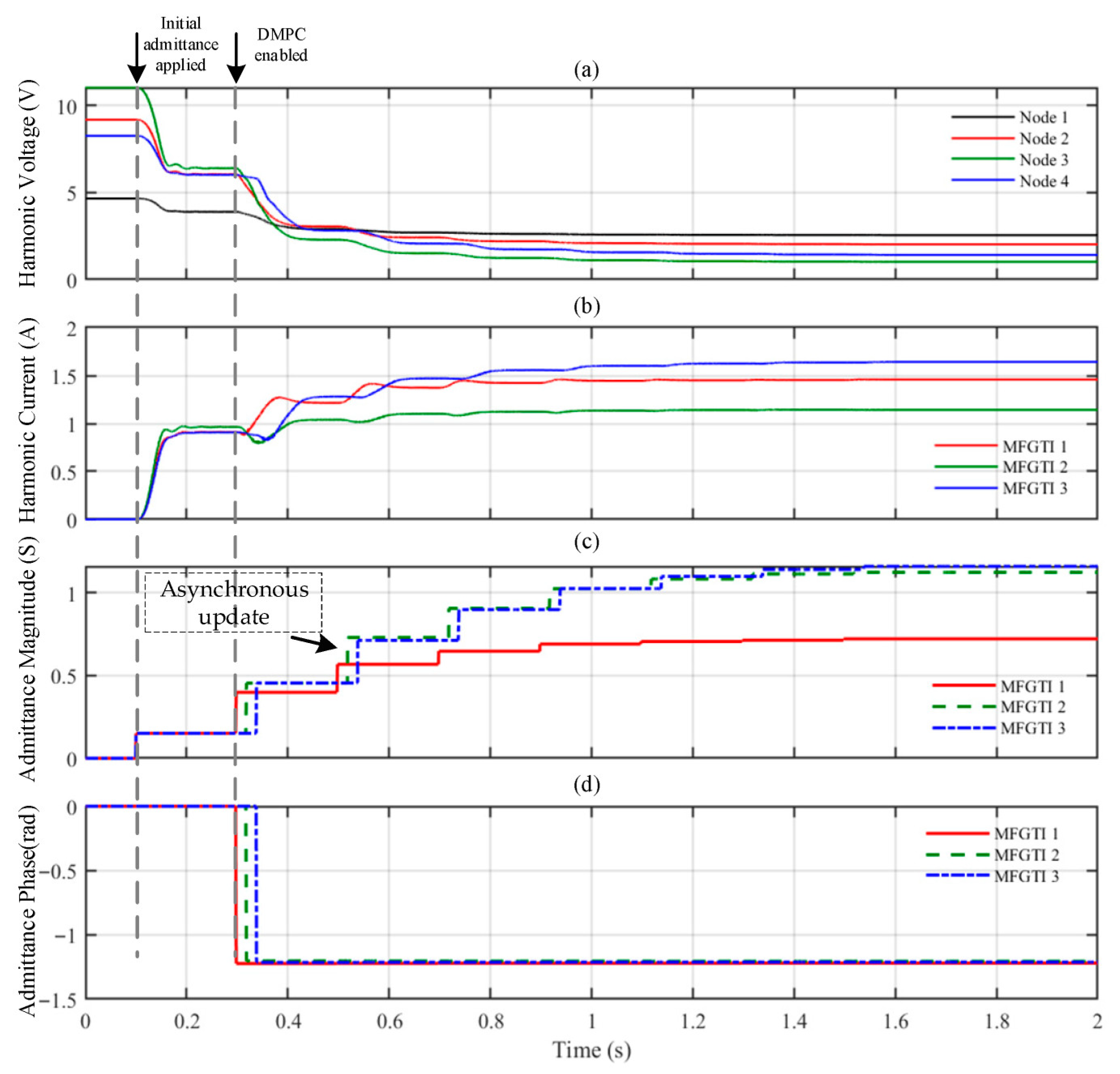
At t = 0.1 s, all MFGTIs are initialized with yh = 0 and θh = 0. The DMPC controller is enabled at t = 0.3 s and updated every 0.2 s. The weighting factors in the cost function are set to αj = [1, 1, 1] and βj = [1, 1, 1].
Figure 7a shows the time profiles of the 7th harmonic voltage magnitudes at all nodes in the distribution network. Before the control is initialized (t < 0.1 s), the network exhibits pronounced harmonic distortion; for instance, the 7th harmonic voltage magnitude at node 3 exceeds 11 V. After the initial virtual admittance parameters are applied at t = 0.1 s, the harmonic voltages decrease markedly across all nodes. When the DMPC is enabled at t = 0.3 s, the virtual admittance parameters are updated every 0.2 s, producing a stepwise reduction in harmonic voltage levels. By t = 1.2 s, the nodal voltages converge to steady values, showing that the proposed strategy suppresses harmonic voltages effectively and yields fast closed-loop convergence.
Figure 7.
Simulation results of the multi-MFGTI DMPC case: (a) 7th harmonic voltage magnitude at each bus; (b) injected harmonic compensation currents of the MFGTIs; (c) evolution of the virtual admittance magnitude yh; (d) evolution of the virtual admittance phase θh.
Figure 7b presents the injected harmonic-compensation current profiles of the MFGTI units. After the units are connected and initialized at t = 0.1 s, they begin injecting compensation currents. When the DMPC controller is enabled at t = 0.3 s, the injected currents are updated via receding-horizon optimization, thereby redistributing the compensation effort among the MFGTIs based on local measurements. Overall, the results show that the proposed strategy enables distributed, cooperative compensation under time-varying harmonic conditions.
Figure 7c,d show the time trajectories of the virtual harmonic-admittance magnitude yh and phase angle θh, respectively. The magnitude yh increases from its initial value via stepwise updates with diminishing step sizes and becomes nearly constant after t = 1.2 s, indicating convergence of the admittance magnitude to a steady operating point. By contrast, after the controller is enabled at t = 0.3 s, the phase angle θh undergoes a rapid adjustment and then remains nearly constant during the subsequent control intervals. This behavior is consistent with the result in Section 2.2 that the near-optimal compensation phase is mainly determined by the local harmonic impedance angle, whereas the admittance magnitude continues to be iteratively updated for coordinated compensation. Consequently, the harmonic voltages and injected compensation currents at all nodes approach steady values under closed-loop operation.
4.3. Performance Under Representative Communication Degradation Scenarios
Since the secondary DMPC layer relies on communication among neighboring MFGTIs, this section further considers representative communication degradation scenarios to evaluate the communication resilience of the proposed method, namely, packet loss in neighboring node measurements and asynchronous updates among local controllers.
4.3.1. Effect of Packet Loss
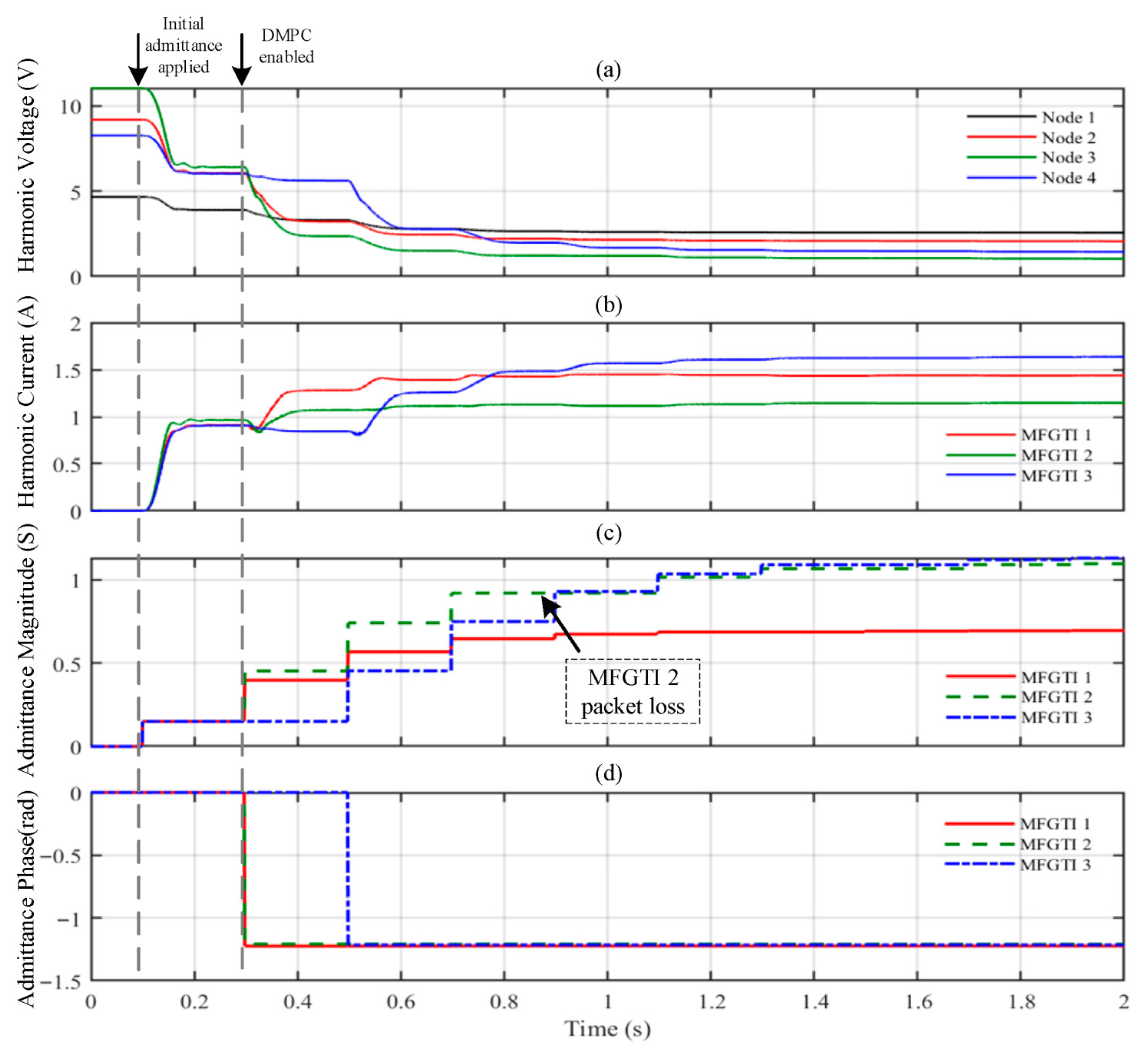
To evaluate the effect of packet loss, an additional simulation is carried out by imposing packet loss on the neighboring node measurements used by the secondary controller. The packet loss rate is set to 20%. When packet loss occurs, the affected MFGTI retains its previous virtual admittance value for the current update interval. The remaining conditions are kept the same as those in Section 4.2.
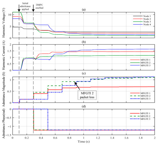
Figure 8 shows that, after the initial virtual admittance is applied, the 7th-harmonic voltages at all buses decrease and are further suppressed after the DMPC layer is enabled. When packet loss occurs, the affected MFGTI temporarily holds its previous virtual admittance value; the label in Figure 8c marks only one representative event for illustration. Although packet loss affects the coordination process to some extent, the harmonic voltages and compensation currents still converge to steady values. This indicates that the proposed method remains effective under packet loss conditions.
Figure 8.
Simulation results of the multi-MFGTI DMPC case under packet loss conditions: (a) 7th harmonic voltage magnitude at each bus; (b) injected harmonic compensation currents of the MFGTIs; (c) evolution of the virtual admittance magnitude yh; (d) evolution of the virtual admittance phase θh.
4.3.2. Effect of Asynchronous Updates
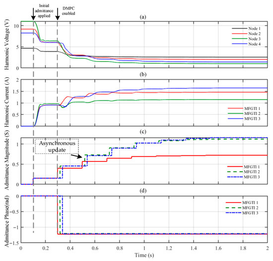
To evaluate the effect of asynchronous updates, an additional simulation is performed in which the local controllers operate with the same update period, while the three MFGTIs are updated with 0.02 s offsets. In this case, the three local controllers start their updates at t = 0.30 s, t = 0.32 s, and t = 0.34 s, respectively. The remaining conditions are kept the same as those in Section 4.2.
Figure 9 shows the simulation results under asynchronous update conditions. As shown in Figure 9a, the 7th harmonic voltages at all buses decrease after the initial virtual admittance is applied and are further suppressed after the DMPC layer is enabled. Due to the different initial update instants of the local controllers, the virtual admittance magnitudes evolve in a staggered manner, as shown in Figure 9c. Although asynchronous updates affect the consistency of the coordination process, the harmonic voltages and compensation currents still converge to steady values, as shown in Figure 9a,b. This indicates that the proposed method can still maintain effective harmonic mitigation under asynchronous update conditions.
Figure 9.
Simulation results of the multi-MFGTI DMPC case under asynchronous update conditions: (a) 7th harmonic voltage magnitude at each bus; (b) injected harmonic compensation currents of the MFGTIs; (c) evolution of the virtual admittance magnitude yh; (d) evolution of the virtual admittance phase θh.
4.3.3. Discussion
For quantitative comparison, the average steady-state harmonic voltage, the maximum steady-state bus harmonic voltage, and the convergence time are extracted for each tested case.
As summarized in Table 4, typical communication degradation causes some variation in coordination performance compared with the nominal case, as reflected in the steady-state harmonic voltage and convergence time. Nevertheless, the proposed method still maintains effective harmonic mitigation under representative communication degradation scenarios.
Table 4.
Performance comparison under communication degradation.
5. Conclusions
Driven by the aggravated harmonic pollution in power-electronics-dominated distribution networks and by the heavy dependence of existing mitigation methods on system-wide information, highly reliable communications, and substantial online computation, this paper proposes a DMPC scheme that leverages the harmonic domain virtual admittance of MFGTIs to coordinate harmonic mitigation across multiple units. The main conclusions are as follows:
- (1)
- The role of harmonic domain virtual admittance in harmonic compensation is examined, and a simulation model of the virtual admittance-based MFGTI harmonic control scheme is developed. The results show that, for a prescribed admittance magnitude, the PCC harmonic voltage is minimized when the admittance phase satisfies θY = −θZL.
- (2)
- The proposed hierarchical harmonic compensation architecture relies only on local and neighborhood information and does not require a central controller to perform power flow calculations, which reduces communication and computational burdens. In addition, it preserves harmonic suppression capability under representative communication degradation conditions.
- (3)
- In the MATLAB/Simulink distribution-network case studies, the proposed DMPC drives the nodal harmonic voltages and compensation currents toward steady values within a small number of update intervals, demonstrating effective coordinated harmonic mitigation under neighborhood information exchange.
In summary, the proposed DMPC-based harmonic domain virtual admittance strategy enables coordinated control of multiple MFGTIs using only neighborhood information exchange, while reducing communication and computational requirements and maintaining stable harmonic suppression in the studied cases. The present study is intended as a first validation step for the proposed control framework. The MATLAB/Simulink case studies provide a direct and repeatable means of verifying the harmonic domain model, the hierarchical control mechanism, and the coordinated closed-loop response under representative operating and communication conditions. However, hardware experiments and real-time emulation are still needed to further assess implementation-related issues.
Author Contributions
Conceptualization, F.C. and W.S.; Methodology, F.C.; Software, Z.W. and F.C.; Validation, M.L. and Z.W.; Formal analysis, J.S. and M.L.; Investigation, H.Y. and Y.F.; Data curation, M.Y. and H.Y.; Writing—original draft preparation, Y.F., J.S. and M.Y.; Writing—review and editing, F.C., W.S. and Y.P.; Visualization, Y.P.; Supervision, W.S. All authors have read and agreed to the published version of the manuscript.
Funding
This project was completed with the support of the State Grid Hunan Electric Power Co., Ltd.’s technology project “Research on Harmonic Source Tracing and Distributed Collaborative Control Technology for High-Penetration Distributed New Energy Distribution Networks” (No. 5216AP250002).
Data Availability Statement
The original contributions presented in this study are included in the article. Further inquiries can be directed to the corresponding author.
Conflicts of Interest
Authors Fang Chen, Zhengyu Wang, Meng Liu, Han Yang, Ming Yang, and Yanyi Fu were employed by State Grid Hunan Electric Power Company Limited Technical Training Center. The remaining authors declare that the research was conducted in the absence of any commercial or financial relationships that could be construed as a potential conflict of interest. The authors declare that this study received funding from State Grid Hunan Electric Power Co., Ltd. The funder was not involved in the study design, collection, analysis, interpretation of data, the writing of this article or the decision to submit it for publication.
References
- Malamaki, K.-N.D.; Christofis, D.-A.; Kryonidis, G.C.; Demoulias, C.S. Voltage harmonic mitigation by distributed renewable energy sources in low-voltage distribution networks: Sensitivity analysis. IEEE Trans. Ind. Appl. 2024, 60, 7656–7671. [Google Scholar] [CrossRef] [Scilit]
- Dan, Y.; Sun, K.; Wang, J.; Fei, Y.; Yu, L.; Sun, L. Novel Distributed Power Flow Controller Topology and Its Coordinated Output Optimization in Distribution Networks. Energies 2025, 18, 2148. [Google Scholar] [CrossRef] [Scilit]
- Shuai, W.; Li, Y.; Zhou, Q.; Peng, Y.; Rong, F.; Shuai, Z. An Optimized Control Strategy for Mitigating Three-Phase Imbalance and Dynamic Economic Operation in Flexible Interconnected Distribution Stations. IEEE Trans. Ind. Appl. 2026, in press. [Google Scholar] [CrossRef] [Scilit]
- Tian, S.; Jia, Q.; Xue, S.; Yu, H.; Qu, Z.; Gu, T. Collaborative optimization allocation of VDAPFs and SVGs for simultaneous mitigation of voltage harmonic and deviation in distribution networks. Int. J. Electr. Power Energy Syst. 2020, 120, 106034. [Google Scholar] [CrossRef] [Scilit]
- Shi, L.L.; Jia, Q.Q.; Lin, L.J.; Wang, N.; Tian, G. Distributed global optimization strategy for harmonic mitigation in power-electronic distribution networks. Proc. CSEE 2020, 40, 2914–2924. [Google Scholar] [CrossRef]
- Zhang, Z.; Yi, H.; Li, Y.; Jiang, X.; Wang, Z.; Zhuo, F. A novel decentralized droop control scheme for multiparalleled APFs with grid current detected. IEEE Trans. Power Electron. 2025, 40, 5922–5938. [Google Scholar] [CrossRef] [Scilit]
- Shuai, W.; Bai, H.; Peng, Y.; Yao, R.; Liu, Y.; Shuai, Z. A DGCRN-based harmonic source localization method for distribution systems with network uncertainty. Int. J. Electr. Power Energy Syst. 2025, 173, 111404. [Google Scholar] [CrossRef] [Scilit]
- Yang, Y.; Yang, P.; Tang, Y.F. Unified control strategy for an interlinking converter with power quality compensation capability. Autom. Electr. Power Syst. 2021, 45, 132–140. [Google Scholar]
- Hoang, T.V.; Lee, H.-H. Virtual impedance control scheme to compensate for voltage harmonics with accurate harmonic power sharing in islanded microgrids. IEEE J. Emerg. Sel. Top. Power Electron. 2021, 9, 1682–1695. [Google Scholar] [CrossRef] [Scilit]
- Acker, T.V.; Ergun, H. Exact Lower Bound for Equitable Harmonic Hosting Capacity. IEEE Trans. Power Deliv. 2025, in press. [Google Scholar] [CrossRef] [Scilit]
- Morales-Paredes, H.K.; Bonaldo, J.P.; Pomilio, J.A. Centralized control center implementation for synergistic operation of distributed multifunctional single-phase grid-tie inverters in a microgrid. IEEE Trans. Ind. Electron. 2018, 65, 8018–8029. [Google Scholar] [CrossRef] [Scilit]
- Chen, J.; Yue, D.; Dou, C.; Li, Y.; Hancke, G.P.; Weng, S. Distributed control of multi-functional grid-tied inverters for power quality improvement. IEEE Trans. Circuits Syst. I Regul. Pap. 2021, 68, 918–928. [Google Scholar] [CrossRef] [Scilit]
- Kim, Y.-J.; Ahn, S.-J.; Hwang, P.-I.; Pyo, G.-C.; Moon, S.-I. Coordinated control of a DG and voltage control devices using a dynamic programming algorithm. IEEE Trans. Power Syst. 2013, 28, 42–51. [Google Scholar] [CrossRef] [Scilit]
- Chiang, S.J.; Chang, J.M. Design and implementation of the parallelable active power filter. In Proceedings of the 30th Annual IEEE Power Electronics Specialists Conference (PESC), Charleston, SC, USA, 27 June–1 July 1999; pp. 406–411. [Google Scholar] [CrossRef] [Scilit]
- Nien, H.-S.; Wu, T.-F.; Hsieh, H.-M.; Shen, C.-L. A parallel-APF system with current sharing controller and load-path control center to improve dynamic response and achieve weighting current distribution. In Proceedings of the 2006 37th IEEE Power Electronics Specialists Conference (PESC), Jeju, Republic of Korea, 18–22 June 2006; pp. 1–7. [Google Scholar] [CrossRef] [Scilit]
- Zhai, H.; Zhuo, F.; Zhu, C.; Yi, H.; Wang, Z.; Tao, R. An optimal compensation method of shunt active power filters for system-wide voltage quality improvement. IEEE Trans. Ind. Electron. 2020, 67, 1270–1281. [Google Scholar] [CrossRef]
- Yang, Z.; Yi, H.; Zhuo, F.; Yin, X.; Wei, W.; Zhang, Y. Optimal siting, sizing and outputting of multiple SAPFs under intelligent nonlinear loads partitioning for system-level harmonic mitigation. IEEE J. Emerg. Sel. Top. Power Electron. 2023, 11, 2600–2617. [Google Scholar] [CrossRef] [Scilit]
- Wang, N.; Zheng, S.; Gao, W. Microgrid Harmonic Mitigation Strategy Based on the Optimal Allocation of Active Power and Harmonic Mitigation Capacities of Multi-Functional Grid-Connected Inverters. Energies 2022, 15, 6109. [Google Scholar] [CrossRef] [Scilit]
- Wang, X.; Wang, Y.; Dai, S. Harmonic mitigation method with multi-resource participation in power distribution networks. IEEE Trans. Ind. Appl. 2025, 61, 5549–5559. [Google Scholar] [CrossRef] [Scilit]
- Peng, X.; Li, Q.; Deng, W.; Dai, S.; Huo, Q.; Han, L. Coordinated harmonic-compensation optimization method for multifunctional grid-connected inverters based on the relative gain array. High Volt. Eng. 2025, 51, 3606–3616. [Google Scholar] [CrossRef]
- Gerdroodbari, Y.Z.; Razzaghi, R.; Shahnia, F. Decentralized control strategy to improve fairness in active power curtailment of PV inverters in low-voltage distribution networks. IEEE Trans. Sustain. Energy 2021, 12, 2282–2292. [Google Scholar] [CrossRef] [Scilit]
- Lin, L.J.; Jia, Q.Q.; Tian, S.Y.; Liang, J.F.; Li, T.C.; Cheng, Z.W. Distributed harmonic mitigation strategy for distribution networks based on a consensus algorithm. Autom. Electr. Power Syst. 2022, 46, 109–117. [Google Scholar]
- Gong, C.; Cheng, Z.; Sou, W.-K.; Lam, C.-S.; Chow, M.-Y. Collaborative distributed optimal control of pure and hybrid active power filters in active distribution network. IEEE Trans. Power Deliv. 2023, 38, 2326–2337. [Google Scholar] [CrossRef] [Scilit]
- Wang, L.; Zhou, W.; Su, C.; Fan, J.; Kong, W.; Li, P. A Distributed Harmonic Mitigation Strategy Based on Dynamic Points Incentive of Blockchain Communities. Energies 2024, 17, 2683. [Google Scholar] [CrossRef] [Scilit]
- Lin, L.; Jia, Q.; Lv, C.; Liang, J.; Luo, P. Partitional collaborative mitigation strategy of distribution network harmonics based on distributed model predictive control. IEEE Trans. Smart Grid 2023, 14, 1998–2009. [Google Scholar] [CrossRef] [Scilit]


Disclaimer/Publisher’s Note: The statements, opinions and data contained in all publications are solely those of the individual author(s) and contributor(s) and not of MDPI and/or the editor(s). MDPI and/or the editor(s) disclaim responsibility for any injury to people or property resulting from any ideas, methods, instructions or products referred to in the content. |
© 2026 by the authors. Licensee MDPI, Basel, Switzerland. This article is an open access article distributed under the terms and conditions of the Creative Commons Attribution (CC BY) license.