


Abstract
The radiant heating and cooling (RHC) system is one of the important air-conditioning methods that simultaneously achieves indoor thermal comfort and building energy efficiency. It is characterized by utilizing low-grade energy sources to provide low-temperature heating and high-temperature cooling, playing a significant role in promoting the development of green and low-carbon buildings. This study firstly introduces the typical heat transfer calculation methods of the RHC system and analyzes the surface heat transfer coefficients of radiant heating and cooling. Subsequently, the factors affecting the thermal performance of the RHC system are discussed from two aspects: relevant physical property parameters and flow channel structures. Finally, the control strategies of RHC systems are summarized to address issues such as condensation, overheating, and long response times. And several conclusive findings are presented that are worthy of further investigation in the future.
1. Introduction
With the development of urbanization and economic growth, energy consumption during the construction and operation of buildings has become the largest portion of global final energy consumption. According to the International Energy Agency (IEA) [1], building operations were responsible for 30% of the world’s final energy consumption and 26% of global energy-related emissions in 2022. Within this total, direct emissions from buildings represented 8%, while indirect emissions from generating electricity and heat for building use accounted for the remaining 18%. Compared to the previous year, energy consumption in the buildings sector increased by approximately 1%. Furthermore, the proportion of building energy consumption in China’s total national energy consumption is expected to continue to grow until 2030 [2]. To achieve energy savings and carbon reduction goals for buildings, heating and cooling systems with higher energy efficiency and lower carbon emissions should receive more attention.
Radiant heating and cooling (RHC) systems utilize the surfaces of environmental objects as heating and cooling sources, exchanging heat through radiant and convective heat transfer. According to the ASHRAE Handbook, the RHC system can be defined as a system where radiant heat transfer accounts for more than 50% of heat exchange within a conditioned space [3]. Since the RHC system only needs to heat or cool the surface of radiant panels rather than the air in the entire room, compared to traditional air systems, the temperature settings for RHC systems are less stringent [4,5]. Additionally, the RHC system can use low-grade energy sources for high-temperature cooling and low-temperature heating [6,7], which demonstrates significant energy-saving potential. Meanwhile, numerous studies have proven that using the RHC system can achieve better temperature uniformity and higher overall satisfaction [8].
According to different standards, the RHC system may have different classifications. From the perspective of radiant surface position, traditional RHC systems include radiant floor and radiant ceiling. However, the increasing amount of research shows that the radiant wall can also provide a viable heating and cooling solution, and in some cases, may even outperform the radiant floor and ceiling [9,10]. Secondly, based on the heat transfer medium, RHC systems can be divided into water-based radiant system, electric-based radiant system, and air-based radiant system [11]. The electric-based radiant system achieves heating and cooling through electric heating elements [12] (such as electric heating films, heating cables, etc.) and thermoelectric modules (TEMs) [13,14]. The air-based radiant system is typically suitable for cases that require a fast temperature response. However, the heat capacity of air is relatively small, which is prone to heat loss. Thus, it is generally less efficient than water-based systems in terms of heat transfer. Thirdly, based on the piping position, RHC systems can be classified into suspended radiant panel system, surface-embedded radiant systems, and thermally activated building systems (TABSs) [15,16], as seen in Figure 1. The most common type is the embedded radiant surface system, where the pipes are installed within the surface of floors, walls, or ceilings, and they are isolated from the building structure thermal mass. Therefore, the insulation layer of this system plays a crucial role in reducing heat loss [17] and shortening the system response time. In the suspended radiant panel system, the water pipes are integrated into lightweight panels, and it is primarily used for ceilings. Since both the top and bottom of the radiant panels serve as heat transfer surfaces, the suspended radiant panel system has a higher total heating and cooling capacity compared to the embedded surface system. Additionally, due to its flexibility in installation, the suspended radiant panel system is an excellent choice for house renovation or retrofit. When the piping is integrated into building structural components, the RHC system is referred to as the thermally activated building system (TABS). The main feature of TABS is its large thermal inertia. But if the thermal storage characteristics of the building mass are properly utilized, the TABS can achieve shorter response time, lower energy consumption [18,19,20,21,22], and shift energy use to off-peak time [23,24], thereby reducing related costs. Furthermore, as the TABS does not require an additional filling layer, it can save more usable space [25].
Figure 1.
Schematic of suspended radiant panel system (a), radiant embedded surface system (b), and thermally activated building system (c) [15,16].
Due to the advantages of the RHC system, it has been widely applied in various buildings, such as office buildings, residential buildings, and airport terminals [26,27,28,29,30]. However, based on its heat transfer principles and inherent characteristics, there are some shortcoming issues, such as high initial investment costs, surface condensation, overheating, long response time, and thermal discomfort in certain scenarios for the RHC system. Therefore, in order to address the challenges and gain a comprehensive and an in-depth understanding of the current research status and trends in the RHC system, this study analyzes and summarizes its heat transfer calculation methods. The analysis reveals that semi-analytical methods provide fast and accurate results, and simplified methods are more suitable for engineering applications. The surface heat transfer coefficient is also examined, which varies significantly with surface position, temperature, and air velocity. A systematic analysis on factors affecting the thermal performance of the RHC system is given, indicating that the significance of various factors varies greatly. In addition, the flow channel structures of radiant terminals are summarized and compared, and some unconventional structural designs are worth further exploration. Finally, control strategies for the RHC system are discussed, confirming that water temperature control is superior to water flow rate control in preventing condensation and reducing temperature fluctuations.
2. Heat Transfer Calculation Method
With the development of the RHC system, its different heat transfer computational methods have emerged. Based on the descriptions and assumptions of heat transfer process in RHC systems, these methods can be mainly divided into analytical method, semi-analytical method, numerical method, and simplified method [31]. For the analytical method, the aim is to derive the critical parameters, namely, the surface temperature of the radiant panel and the heat transfer flux. The heat transfer equations of the radiant panel can be solved using the separation of variables method, the Fourier decomposition method, or the Laplace transformation method [32]. However, due to the requirement for detailed mathematical descriptions and solution process complexity, this method has very stringent application conditions and generally only solves one-dimensional problems, so it will not be elaborated in this study. The comparison of characteristics of different calculation methods is shown in Table 1.
Table 1.
Characteristics of different calculation methods.
2.1. Semi-Analytical Method
To address the drawbacks of the analytical method, some researchers have proposed the semi-analytical method, which involves decomposing the problem into known analytical solutions and using numerical methods to solve the more complex aspects. Tye-Gingras and Gosselin [33] proposed a semi-analytical modeling method for low thermal mass serpentine radiant panels. Their approach accounts for the temperature gradient along the flow direction and the thermal asymmetry between the tubes, while neglecting the influence of the semi-circular tube endings, as seen in Figure 2. And the method introduces a temperature asymmetry function δ and solves it iteratively with the forward finite difference method (FDM). Thereby, they obtained the panel surface temperature distribution and heat transfer rate. They compared this semi-analytical model with the analytical model recommended by ASHRAE, which assumes thermal symmetry, and investigated the effects of neglecting temperature gradient and semi-circular tube endings using a two-dimensional finite volume method (2D FVM). The results demonstrated that for panels with various geometries and operating parameters, the errors on heat transfer introduced by these assumptions were negligible, and the performance difference between serpentine and parallel layout panels was insignificant (typically less than 1%).
Figure 2.
Schematic diagram of introducing a temperature-asymmetry function and neglecting the semi-circular tube endings [33].
On the other hand, Merabtine et al. [32] focused on the surface temperature of heating floors under transient conditions and introduced a novel simplified semi-analytical method. The method incorporates the logarithmic time profile applied to the heat exchangers. In the function, the steady-state average surface temperature is obtained directly through the analytical method. And the response factors, namely, τ and td, are obtained by the design of experiments method and a validated two-dimensional finite difference method (2D FDM). The numerical values were in close agreement with experimental data. Compared to experimental results, the maximum relative deviation on the computed surface temperature was within 4% for the semi-analytical method.
2.2. Numerical Method
The numerical method refers to the process of discretizing continuous heat transfer equations into algebraic equations. Commonly, numerical methods include the finite difference method (FDM), the finite volume method (FVM), and the finite element method (FEM). To analyze the impact of design and physical control factors and their interactions on the average surface temperature and thermal time constant, Merabtine et al. [34] constructed polynomial meta-models based on a 2D FDM full factorial design. The computational results showed that the 2D FDM exhibited good concordance with experimental results compared to both the 3D FVM and the Modelica model. The maximum error in the surface temperature (Ts) of radiant slab was within 3.4%, while the errors at the center and bottom (Td8 and Td11) were within 6.4% and 8.2%, respectively. Additionally, the 2D FDM was 1200 times faster than the 3D FVM. Secondly, to better simulate heat transfer within the pipes, Jin et al. [35] proposed a two-dimensional numerical method based on the FVM that utilized a composite grid. In this method, a rectangular coordinate system is used in the floor structure layers (regions I, II, and III in Figure 3), and polar coordinate is used in the pipe sections (regions IV and V in Figure 3). Under varying temperature and flow velocity conditions, the absolute errors between measured and numerical values of the floor surface temperatures were less than 0.3 °C and 0.56 °C, respectively.
Figure 3.
Schematic diagram of the two-dimensional numerical method with a composite grid [35].
In addition, Xing et al. [36] developed a numerical program based on FEM to calculate view factors and radiation temperature fields and used the Monte Carlo method to correct the singular solution problems generated by FEM. The program successfully predicted the mean radiant temperature (MRT) of radiant cooling indoor environments. The root mean square error (RMSE) and mean absolute percentage error (MAPE) compared to experimental results were 0.24 °C and 0.93%, respectively.
2.3. Simplified Method
Due to the relatively large computational load required by these numerical methods, which will lead to long solution time in some cases, researchers have proposed several simplified methods. The methods employ reasonable assumptions for the computational model, focusing on the aspects of primary concern and thereby enabling direct solutions through straightforward mathematical approaches. Two models are introduced here: the thermal resistance model, proposed by Ren and Wright [37], and the fin model.
For determining the temperature distribution on the floor surface, Li et al. [38] proposed an equivalent thermal resistance method (ETRM) for analyzing heat transfer process in multilayer floor structure (Figure 4a). The method assumes a virtual layer with even temperature distribution at the level of the pipes. Then the floor heat transfer process is simplified into a one-dimensional series thermal resistance model. Due to the property of thermal resistances in series, the thermal resistance should be equal under the same temperature difference. The floor is thus homogenized by adjusting the thickness of structural layers with different thermal conductivities. This allows an analytical solution to the heat transfer equation to be derived, specifically the temperature function. Finally, the respective thermal resistances are determined based on the temperature solution. And the simplified calculation of the floor surface temperature exhibited an absolute error of less than 0.4 °C compared to the experimental results. Furthermore, Ding et al. [29] used a similar simplified method to construct a thermal resistance model for radiant multilayer floor (Figure 4c). In addition to the upward heat transfer from the water flow, the model also accounts for heat transfer to the insulation layer, the floor slab, and the air in the space below. They analyzed the heating capacity, heat loss, and surface temperature of the floor. The comparison results under four different operating conditions demonstrated that the calculated data agree well with the measured data. The relative errors between the measured and calculated upper surface heat flux are within 5%. The errors between the measured and calculated values are within ±0.5 °C for the upper surface temperature and within ±3.5 W/m2 for the lower surface heat flux. Meanwhile, to study the two-dimensional dynamic heat transfer process of the concrete radiant cooling slab, Tian et al. [39] introduced a core temperature layer (Figure 4b), similar to the virtual layer mentioned above, and proposed an unsteady-state heat transfer model based on the reaction coefficient method. They validated the model under four different steady-state conditions and six different unsteady-state conditions, with the relative errors between the calculated and experimental values being within 1.5% and 7%, respectively.
Figure 4.
(a) Schematic diagram of the equivalent thermal resistance of multilayer floor structure [38]. (b) Schematic diagram of heat transfer process with the core temperature layer [39]. (c) Schematic diagram of the thermal resistance model of the radiant multilayer floor [29].
Secondly, Kilkis proposed a composite-fin model (Figure 5a), which treats the floor surface temperature above the tube as the fin base temperature, and calculates the horizontal temperature distribution of the floor surface based on fin heat dissipation. After that, considering the horizontal thermal conduction within the structural layer gives rise to a temperature decrease in the pipe top floor surface. Liu et al. [40] introduced a fin base temperature coefficient k based on Kilkis’ model, thereby proposing a revised composite-fin model. Based on the revised composite-fin model and the equivalent thermal resistance model, computational results exhibit deviations of less than 10% compared to those from numerical simulations. Specifically, for the floor structure commonly employed in practice, the error remains within 5%. In contrast, the original Kilkis model yields an error of around 20% under the same conditions. Moreover, Yu et al. [41], building upon the work in [33], introduced a heat transfer calculation method for the absorber plate in flat-plate-type solar collectors and proposed a simplified model for serpentine-tube ceiling radiant cooling panels (CRCP-s). The model divides the panels into N sections. The tubes are unrolled and attached on a single strip plate, which is treated as a straight fin with a length of N × L (Figure 5b,c). Here, the junction in contact with the tube can be regarded as the fin base, while the centerline between two adjacent tubes can be considered as the fin end. Experimental tests were performed on two types of CRCP-s. A comparison revealed that the model predictions agreed well with the experimental measurements within the temperature range relevant for space cooling, demonstrating deviations acceptable for most engineering applications.
Figure 5.
(a) Schematic diagram of the composite fin model based on Kilkis [40]. (b) Schematic diagram of the fin slice [41]. (c) Schematic diagram of the unrolled and connected CRCP-s [41].
3. Surface Heat Transfer Coefficient
In the calculation methods discussed in Section 2, heat transfer coefficients are predominantly specified as known parameters. They play a critical role in simulation analysis and preliminary design. Moreover, for the RHC system, the most important and intuitive quantity representing its thermal performance is the heat transfer coefficient between the radiant surface and indoor environment [42]. A summary of the surface heat transfer coefficients is given in Table 2.
Table 2.
Surface heat transfer coefficients with slight modifications.
The heat transfer coefficients provided in Table 2 are predominantly measured in the experiments. Most of these tests are conducted in climate chambers with volumes ranging from 5 to 50 m3 [43,45,52,53,54,56,62], while others are in full-scale experiments [55,60]. The general procedure for calculating the heat transfer coefficient involves first measuring and calculating the total heat flux and the radiant heat flux. The convective heat flux is then obtained by subtracting the radiant heat flux from the total heat flux. Finally, the heat transfer coefficient is derived by dividing each respective heat flux by its corresponding temperature difference. Specifically, the reference temperature for the radiant heat transfer coefficient is the average unconditioned surface temperature; for the convective heat transfer coefficient, it is the air temperature; and for the total heat transfer coefficient, it is the operative temperature. The common calculation approach for the heat transfer coefficients is summarized in Table 3.
Table 3.
The common calculation approach for heat transfer coefficients.
3.1. Total Heat Transfer Coefficient
Determining the convective and radiant heat transfer coefficients of radiant surface is crucial for accurately analyzing the heating/cooling capacity of the RHC system, as well as its thermal comfort and energy consumption characteristics. To facilitate engineering applications and system-scale calculations, some standards, such as REHVA [47], EN1264-5 [48], EN15377-1 [49], and ISO 11855-2 [50], have introduced the total heat transfer coefficient, which combines both convective and radiant heat transfer coefficients. These standards either provide a specific value or offer a formula related to the difference between the average radiant surface temperature and the operative temperature.
As shown in Table 1, the total heat transfer coefficient for wall heating and cooling is mostly around 8 W/m2 · K [47,48,49,50,54,60,61,62]. Corresponding studies show that the total heat transfer coefficient for ceiling cooling ranges from 8.4 to 13.2 W/m2 · K [47,48,52,55,56], which is significantly higher than that for ceiling heating, which averages around 7 W/m2 · K [47,48,49,50,52,53,54,55]. However, when using floor heating, the total heat transfer coefficient ranges from 9.9 to 11 W/m2 · K [44,47,48], while for cooling, it ranges from 5.7 to 7.0 W/m2 · K [43,47,48,49,50,51]. These studies indicate that ceiling cooling and floor heating are more suitable. However, this is not always the case. In recent years, floor radiant cooling systems have become increasingly popular in buildings with large glass areas, such as airports and train stations [26,27,63]. This is because the short-wave solar radiation can be immediately absorbed by the cooled floor before heating the space, removing the heat directly from the area, thereby achieving better cooling performance [28,64].
Although the total heat transfer coefficient is convenient for calculation, the values obtained by Andrés-Chicote et al. [56] indicate that, depending on particular characteristics of insulation and outdoor environment, different combinations of TAUST and Ta can result in the same operative temperature but lead to quite distinct total heat fluxes. Therefore, for the accurate assessment of heat transfer in practical applications, the use of a single operative temperature and a combined total coefficient is not sufficiently reliable. It is essential to analyze radiant and convective heat transfer processes independently.
3.2. Radiant Heat Transfer Coefficient
The radiant heat transfer coefficient primarily depends on the intrinsic material properties, surface characteristics, temperature, and view factors. When the material is specified, temperature variation is minimal, and room dimensions are similar, both the emissivity and view factors tend to be comparable. Consequently, the radiant heat transfer coefficients are likely to show little variation. This is indeed the case. The radiant heat transfer coefficient is often considered constant in many studies [43,44,51,52,53,54,55,56,57,60,61,62], typically around 5.5 W/m2 · K. This simplifies the original Stefan–Boltzmann law into a formula, where the heat flux varies linearly with the temperature difference, providing great convenience for engineering applications and simulation calculations.
However, the value of 5.5 W/m2 · K is mostly proposed when the material emissivity is between 0.9 and 0.95, and the radiant heat transfer coefficient cannot be considered as such in all cases. Zhao et al. [26] studied the effect of material emissivity on indoor long-wave radiation in large spaces, pointing out that the radiant heat transfer coefficient decreases as the emissivity of the indoor surfaces decreases, i.e., from a baseline of 5.2–5.5 W/m2 · K to 3.8 W/m2 · K when the emissivity of the ceiling is 0.4. That is, when the emissivity of many commonly used metals and advanced materials (e.g., low-emissivity coatings) is between 0.2 and 0.9, the effect of material surface emissivity should be considered when calculating radiant heat transfer.
3.3. Convective Heat Transfer Coefficient
Compared to the relatively stable radiant heat transfer coefficient, the convective heat transfer coefficient varies more significantly with surface position, temperature, and air velocity. In other words, the differences in the total surface heat transfer coefficients of various RHC systems are largely due to differences in convective heat transfer coefficients.
This provides us with an idea: if we want to improve the performance of RHC systems, we may take measures to enhance the system convective heat transfer effect. For example, Zhang et al. [55] attempted to use inclined fins to increase the convective heat exchange area, thereby improving the heating/cooling performance of the suspended ceiling radiant panel. The results showed that the cooling capacity of test panel was 19% larger than that of the regular suspended panel, but the improvement in heating capacity was limited. Jeong and Mumma [65] estimated the cooling capacity of one suspended metal ceiling radiant cooling panel after adding mechanical ventilation by using a simplified model. The results showed that mixed convection (i.e., natural convection plus forced convection) could enhance the cooling capacity of radiant panels, with a potential enhancement of over 17%.
It can be seen that there are still many differences between studies regarding the heat transfer coefficient. This may be due to the use of different measurement conditions and methods (i.e., calculation approach for heat transfer, reference temperature, temperature stratification, ventilation mode, room and surface dimensions, and load type) [42]. To determine the appropriate heat transfer coefficient, its purpose and application must first be identified, and then conditions that match those purposes should be selected.
4. Factors Affecting the Thermal Performance of RHC System
When analyzing the thermal performance of RHC systems, there are two main aspects worth considering. One is the heating/cooling capacity of the RHC system, which determines the working ability of the radiant system. The other is the uniformity of the radiant surface temperature distribution, which affects the thermal comfort of indoor occupants. Meanwhile, a smaller temperature difference can provide more favorable operative temperature and avoid overheating in the heating system and condensation in the cooling system, due to local high or low temperature. The factors affecting the thermal performance of the RHC system are shown in Table 4.
Table 4.
Factors affecting the thermal performance of the RHC system.
4.1. Pipe Diameter and Thermal Conductivity
The influence of the pipes on thermal performance is primarily reflected in the magnitude of their thermal resistance. According to the calculation formula for the thermal resistance of a cylindrical wall to heat conduction, the thermal resistance is proportional to the logarithm of the ratio between the outer and inner diameters, while being directly inversely proportional to the thermal conductivity. Theoretical analysis therefore indicates that the impact of thermal conductivity outweighs that of variations in pipe diameter and wall thickness. However, in practical applications, the impact of limited changes in pipe wall thickness on thermal resistance is not significant. The research on pipe thermal parameters mainly focuses on pipe diameter and thermal conductivity.
Regarding pipe diameter, Sattari and Farhanieh [73] used the finite element method to study the effects of design parameters on the performance of a typical radiant floor heating system. The results showed that pipe type and diameter had minimal effects on the thermal performance of heating floor system. Tang et al. [70] established a simplified model to predict the surface temperature distribution of a prefabricated ceiling radiant panel. The results indicated that the pipe diameter had a negligible effect on the maximum and minimum surface temperatures and the uniformity of surface temperature. Yang’s study pointed out that the pipe diameter did not affect the thermal performance of the pipe-embedded wall [78]. Xie et al. [67] conducted numerical analysis of the capillary ceiling radiant cooling panel and noted that the temperature non-uniformity coefficient was negatively correlated with the pipe diameter, while the cooling capacity was positively correlated with pipe diameter. However, the influence of pipe spacing was greater than that of pipe diameter.
With respect to thermal conductivity, Zhang et al. [72] provided a simplified calculation for the parameters of radiant floor, pointing out that when the thermal conductivity of the pipe was 0.4 W/(m · K), even with very thin pipes, their impact on the total thermal resistance remained around 5%. Jin et al. [35] conducted numerical simulation of the radiant floor cooling system using the finite volume method. The results showed that if the thermal resistance of the pipe was neglected, the floor surface temperature error was 0.4 °C. When the thermal conductivity was 0.22 W/(m · K), the temperature error was 0.74 °C. If the pipes were made of copper or aluminum with a thermal conductivity more than 100 W/(m · K), the error was very small. Yu et al. established a simplified model for ceiling radiant cooling panels (CRCPs) and conducted the thermal performance analysis by using the model [41]. The results indicated that the cooling capacity rose sharply (approximately 4 W) with increasing tube thermal conductivity up to a value of 1.0 W/(m · K). Beyond this threshold, the rate of increase slowed noticeably. Once the thermal conductivity exceeded 10 W/(m · K), its influence became marginal and could be disregarded. Therefore, metallic tubes such as those made of copper, iron, or steel, which typically exhibit thermal conductivity above 50 W/(m · K), had a negligible impact on the cooling capacity of the CRCP system. In contrast, polymer-based tubes such as PE-X, with a thermal conductivity of around 0.38 W/(m · K), significantly affected cooling performance.
From the above studies, it can be found that pipe diameter is not the main focus for optimizing the thermal performance of the RHC system. Secondly, the thermal conductivity of pipes affects the magnitude of the pipe thermal resistance, which in turn significantly affects the thermal performance of the RHC system, especially for materials with low thermal conductivity. However, materials with high thermal conductivity have almost no effect.
4.2. Pipe Spacing
When the room dimensions are fixed, the pipe spacing affects both the total pipe length and the cooling/heating source density, which in turn directly influences the heat flux and the temperature distribution of the radiant surface.
As for radiant cooling systems, Yu et al. [41] found that for ceiling radiant cooling panels, the cooling capacity decreased linearly with the increase in tube spacing within the applicable range of 0.05–0.3 m. When the tube spacing increased by 0.05 m, the cooling capacity decreased by approximately 3 W. Similarly, the research by Xie et al. [67] showed that the temperature non-uniformity coefficient of capillary ceiling radiant cooling panel was positively linearly correlated with pipe spacing, while the cooling capacity was negatively linearly correlated with pipe spacing. Tian et al. [69] proposed a computational model for optimizing and designing the air-layer radiant cooling panel. The study demonstrated that as the pipe spacing increased from 0.05 m to 0.3 m, the minimum surface temperature rose by approximately 2 °C, the surface temperature difference increased by about 0.7 °C, and the cooling capacity decreased by nearly 25 W. Considering both cooling capacity and cost, the most recommended pipe spacing values are 0.15 m and 0.2 m.
For radiant heating systems, Gao et al. [74] compared five kinds of underfloor heating pipe layouts with supply water temperature at 50 °C and return water temperature at 40 °C. They found that the floor temperature field became less homogeneous as the pipe spacing increased, while overheating occurs at a spacing of 300 mm. Therefore, the optimal layout was the underfloor heating pipe uniformly laid at 400 mm center spacing. Similarly, Fu et al. [75] analyzed the heat transfer characteristics of capillary and traditional pipe radiant heating floors under different operating conditions and pointed out that pipe spacing had a significant impact on the variation in surface temperature difference. The unevenness of floor surface temperature distribution increased as the pipe spacing grew, and when the pipe spacing was 300 mm with a filling layer of fly ash ceramsite concrete, the maximum temperature difference reached 4.2 °C. However, the research by Sattari and Farhanieh [73] showed that the number of pipes had no significant effect on the performance of the floor radiant heating system. The pipe counts configured in their study were 13, 14, and 15, respectively. Given the relatively small differences between these values, this may have led to the conclusion. The global sensitivity analysis (GSA) by Yang et al. [78] showed that the optimal range for pipe spacing (PS) in pipe-embedded heating walls was 100–250 mm. Meanwhile, Yang et al. [23] utilized the thermal mass of building structures to comparatively analyze the impact of 100–500 mm pipe spacing on the thermal performance of pipe-embedded heating floors at four different supply water temperatures. The results indicated that the pipe spacing of 300 mm could ensure thermal comfort without causing overheating and does not require long heating times.
As evidenced by the aforementioned studies, there is no universally optimal value for pipe spacing. The most suitable spacing varies depending on the system configuration, room dimensions, and load types. Excessively large pipe spacing may result in poor temperature uniformity across the radiant panel surface, whereas overly small spacing may cause issues such as overheating, increased pumping power, and higher material costs. Therefore, the reasonable pipe spacing plays a crucial role in enhancing both surface temperature uniformity and heat transfer performance.
4.3. Flow Velocity
From the perspective of convective heat transfer between the working fluid and the pipe wall, flow velocity affects the convective heat transfer coefficient, which in turn affects the thermal performance of the RHC system. Wang et al. [71] established simplified and numerical models to calculate the heat transfer and surface temperature of RHC systems. The results showed that as the water flow velocity increased, there was a dramatic change in both heat transfer and surface temperature during the transition from laminar flow to transitional flow. For prefabricated ceiling RHC systems, a larger water flow velocity was required for the transition from laminar flow to transitional flow compared to prefabricated floor RHC systems. In the simplified model calculation by Yu et al. [41], 15 different water flow values were used. The results showed that as the flow rate increased from 0.016 kg/s to 0.017 kg/s, corresponding to the transition from laminar to turbulent flow, the cooling capacity surged by approximately 2 W. In the turbulent region, the cooling capacity increased slowly with the increase in flow rate. In the laminar region, the cooling capacity decreased with a reduction in flow rate, and when the flow rate was less than 0.01 kg/s, the cooling capacity dropped sharply. Hence, for practical applications, the flow velocity should be large enough to keep the flow in the turbulent regime.
In addition, Yin et al. [68] conducted experimental studies on the heat transfer performance of capillary radiant cooling panels. The results showed that as the water velocity increased from 0.25 m/s to 0.45 m/s, the heat transfer rate of the radiant panel rose significantly from 30 W/m2 to 62 W/m2. For certain capillaries, the optimal flow velocity for achieving the best heat transfer performance was 0.45 m/s. The research by Xie et al. [67] indicated that the temperature non-uniformity coefficient of the capillary ceiling radiant cooling panel was negatively correlated with water flow velocity. When the inlet water flow velocity varied in the range of 0.05–0.10 m/s, the heat transfer between the ceiling surface and the indoor environment significantly increased by 12%. Ye et al. [66] conducted experimental analysis on the thermal performance of the ceiling radiant cooling panel (CRCP) with a segmented and concave surface. The results showed that when the inlet water temperature increased from 15 °C to 24 °C, the cooling capacity decreased by 45%, 50%, 42%, and 40% at the flow rates of 2 L/min, 4 L/min, 6 L/min, and 8 L/min, respectively. The cooling capacity did not exhibit a simple linear relationship with flow rate, such as the relationship with inlet water temperature. When the inlet water temperature was less than or equal to 21 °C, the flow rate significantly affected the cooling capacity. However, when the inlet water temperature was greater than 21 °C, the cooling capacity remained the same.
From the above studies, it can be found that there are two aspects of effect caused by flow velocity on the thermal performance of the RHC system. Firstly, from the perspective of convective heat transfer within the pipe, turbulent flow provides better performance than laminar flow. The other is the heat exchange time of the working fluid inside the pipe, which is related to both the pipe length and flow velocity. When analyzing the impact of flow velocity on heat transfer rate, temperature is also a crucial factor that cannot be ignored. If the temperature difference between the supply water and the indoor environment is small, increasing the flow velocity may not be of much significance to improve the heat transfer rate. Instead, when the temperature difference between the supply water and the indoor environment is large, increasing the flow velocity will have a very significant effect.
4.4. Water Temperature
According to the second law of thermodynamics, the temperature of working fluid directly affects the heat transfer rate in the RHC system. Based on the principles and settings of simplified models and numerical simulations, heat flux should inherently vary linearly with water temperature. And in the assumptions of many calculation models [33,69,70,71], the average supply and return water temperature of radiant system is employed for analysis, rather than only the supply water temperature. For example, the results from Wang et al. [71] showed that under both heating and cooling conditions, the heat transfer rate and surface temperature of RHC systems changed linearly with the average water temperature.
As the working fluid flows inside the pipe, the difference between the fluid temperature and the initial temperature becomes more pronounced, which in turn affects the uniformity of the temperature distribution on the radiant surface. The research by Xie et al. [67] indicated that the cooling capacity and temperature non-uniformity coefficient of the capillary ceiling radiant cooling panel were negatively linearly correlated with the temperature of the chilled inlet water. However, the study by Tang et al. [70] on the surface temperature distribution of the prefabricated ceiling radiant panel showed that the supply water temperature had a significant impact on the maximum/minimum surface temperature, but no effect on surface temperature uniformity. This discrepancy may be related to their different definitions of temperature uniformity. Tang et al. [70] defined surface temperature uniformity (γ) from the perspective of the radiation system operating performance as the ratio of the difference between the average surface temperature of radiant panel and the indoor temperature to the difference between the maximum/minimum surface temperatures (corresponding to heating and cooling) and the indoor temperature. In contrast, Xie et al. [67] defined the temperature non-uniformity coefficient (TNC) index as the ratio of root mean square deviation of the temperatures at various test points to the average surface temperature. Nevertheless, they both reached the same conclusion that the flow velocity had a greater impact on the temperature uniformity of the radiant panel surface than the supply water temperature.
The influence of water temperature on the surface temperature uniformity primarily depends on the temperature difference between the supply water and the indoor environment, as well as the heat exchange duration of water within the pipes. Regarding the heat transfer rate, due to the low-temperature heating and high-temperature cooling characteristics of the RHC system, and considering energy consumption, the setting of the supply water temperature is also constrained. The heating temperature range is typically 25–40 °C, while the cooling range is 16–20 °C [15,79]. However, the supply water temperature remains the most direct factor affecting the heat transfer rate.
4.5. Structural Layer Thickness and Thermal Conductivity
From the perspective of heat conduction among structural layers, the thickness and thermal conductivity of structural layers can affect their thermal resistance, thereby influencing the thermal performance of the RHC system.
For different structural layers, the thermal performance analysis of the ceiling radiant cooling panels by Yu et al. [41] showed that when the surface plate thickness was below 0.5 mm, the cooling capacity decreased markedly as the thickness was reduced. Beyond 0.5 mm, further increases in thickness resulted in diminishing improvements in cooling capacity. Once the thickness exceeded 2 mm, its effect became negligible. Therefore, it was advisable to maintain a plate thickness of at least 0.5 mm, with 1 mm being the recommended value. Lu et al. [76] conducted simulation experiments on prefabricated lightweight radiant floor heating (FRH) under intermittent operation. They argued that the uniform heating layer and surface layer played crucial roles in enhancing the dynamic performance of FRH. The thermal conductivity and the thickness of uniform heating layer should be greater than 200 W/(m · K) and 0.4 mm, respectively. And the thickness of the surface layer should be less than 0.015 m. Jing et al. [77] established numerical models for different floor structures of the proposed new type of the radiant floor heating system and verified by experiments. The results showed that under the same conditions, the surface temperature of the wooden floor was approximately 2 °C lower than that of the cement tile due to the lower thermal conductivity of its material. However, the wooden surface demonstrated a more uniform temperature distribution. When the surface layer was ceramic tile, for every 10 mm increasing in the filling layer thickness, the floor surface temperature above the heat pipes dropped by about 0.5 °C. As the thickness of the filling layer increased, the temperature unevenness of the floor surface decreased, and the comfort of the floor could be enhanced. The appropriate thickness of the filling layer was 60 mm.
From the above studies, it can be seen that increasing the thermal conductivity of the structural layer is beneficial for heat transfer. Increasing the thickness of the structural layer helps improve the temperature uniformity of the radiant panel surface, but it also increases the structural layer thermal resistance and the response time. Moreover, increasing the filling layer thickness will raise the construction costs and occupy more indoor space. Consequently, the selection of structural layer thickness needs to balance the impacts on both thermal performance and costs.
5. Flow Channel Structure
Within hydronic networks, the serpentine flow arrangement is a commonly adopted design. In this configuration, the working fluid flows through a continuous circuit that covers the entire panel area, composed of linear segments connected by return bends arranged in series [80]. Common flow channel configurations also include spiral and parallel arrangements. And beyond these designs, some researchers have departed from traditional concepts to restructure conventional flow channels and investigate novel configurations, with detailed information summarized in Table 5.
Table 5.
Flow channel structures.
For the serpentine flow channel, Radzai et al. [81] conducted numerical simulations on three pipe configurations of the radiant cooling panel by varying the number of inlets and outlets in the serpentine flow channel structure. The results showed that the two-inlet-two-outlet counterflow serpentine flow configuration exhibited better temperature uniformity. The conventional serpentine flow configuration showed the lowest cooling performance, with a pressure drop of 129.4225 Pa. Increasing the number of inlets and outlets in the serpentine flow structure might not have a significant impact on cooling performance, but the location of the pipe inlets and outlets, as well as the compactness of the pipe arrangement, might affect the cooling performance of the radiant panel. Furthermore, Ye et al. [82] designed radiant cooling panels with three different pipe spacings and analyzed their heat transfer performance after combining them with seven modules with variable pipe spacing (VPS). The results showed that, compared to traditional modules with equal pipe spacing (EPS), the VPS modules exhibited better total heat transfer performance, more uniform surface temperature distribution, and lower average surface temperature under various water supply and return temperature differences.
With respect to the spiral configuration, Okamoto et al. [57] proposed a simplified calculation method for estimating the heat flux of ceiling radiant panels and compared the thermal performance of serpentine and spiral pipe radiant panels. In the case of spiral piping, in regions with higher pipe density, the temperature distribution was more uniform, and the heat flux was larger than that of the serpentine pipe. However, the surface temperature difference between areas with higher and lower pipe densities in the spiral pipe was larger than in the serpentine pipe. In the case of serpentine piping, the lower the pipe density, the smaller the temperature difference on the panel surface, and the more uniform the temperature distribution during heating. Moreover, Oubenmoh et al. [83] studied the thermal behavior of serpentine, counterflow spiral, and modulated spiral floor heating systems with specific pipe spacing using a two-dimensional finite volume method. The results showed that a better thermal homogeneity of the floor was obtained for the modulated spiral configuration. Additionally, compared to other configurations, the modulated spiral configuration had the lowest pressure loss.
Regarding parallel arrangement, Mosa et al. [84] investigated the influence of the aspect ratio (W/L) on the thermal performance of serpentine and parallel flow channel radiant cooling panels. For serpentine channels, an aspect ratio of 0.24 resulted in better temperature uniformity. While higher aspect ratios could slightly enhance the cooling capacity of the radiant panel, this improvement was accompanied by a significant increase in pressure loss. Regardless of the aspect ratio, parallel flow channels exhibited a superior ratio of cooling capacity to pumping power compared to serpentine configurations. Furthermore, when the variable-diameter design was applied to the main and branch pipes, the nearly square configuration (with an aspect ratio of 1.05) outperformed all other structural designs and featured the shortest fluid path. In addition, Xing et al. [85] modified both serpentine (S-type) and parallel (P-type) flow channels to reduce the impact of contact thermal resistance. The flow channels were engraved into an insulating cover, and a metal panel serving as the cooling surface was embedded within it. Numerical simulations indicated that, under identical cooling capacity of 80.1 W/m2, the modified panels allowed an inlet water temperature approximately 4 °C higher than that of conventional pipe–plate systems. Hydraulically, the pressure drop of the S-type panel was 726.9 Pa, while that of the P-type panel was only 55.7 Pa. Regarding the effect of geometric dimensions, for a P-type panel with a fixed width, increasing its length helped reduce the ratio of pressure drop to cooling capacity. If the area of the P-type panel was fixed, the optimal performance was achieved at an aspect ratio of 1.0. To mitigate the impact of uneven chilled water distribution on cooling capacity, they developed P1- and P2-type flow channels. Comparison results showed that for surface materials of aluminum and polymer, the cooling capacity of the panels with the new flow channels increased by approximately 6% and 8%, respectively.
In the case of some novel channel configurations, based on previous studies, Mosa et al. [80] further investigated the impact of six structures with higher degrees of freedom on the performance of the suspended radiant cooling panels. The results indicated that the counterflow configuration led to superior temperature uniformity. The branched design yielded a significantly lower pressure drop. All structural designs demonstrated higher overall efficiency compared to the standard serpentine configuration, with the canopy-to-canopy (parallel) design exhibiting the best performance. On the other hand, Jing et al. [77] developed a novel radiant floor heating system incorporating micro heat pipe arrays (MHPAs). In this design, the piping section was composed of multiple MHPAs intersecting at one end with micro-channel flat tubes oriented in opposing directions. Wood blocks were installed at the opposite end of the arrays to establish an inclination angle exceeding 2°, ensuring efficient operation of the MHPAs. Under identical operating conditions, the new system achieved a heat flux of 175.7 W/m2, outperforming conventional circular water pipe radiant floors by 31.9%. Furthermore, when compared at the same heat transfer rate, the average heat flux of the MHPA-based system was 19.9% higher than that of the traditional floor heating system. The supply water temperature required by the MHPA floor was also approximately 5 °C lower than that of conventional systems. As flow rate increased, the flow resistance rise in the novel system remained consistently lower than that in the conventional round pipes, with this advantage becoming more pronounced at higher flow rates. Moreover, Hassan and Kaood [86] proposed a passive enhancement approach by internally finning the copper tubes. By means of a validated computational model, they conducted a comprehensive performance evaluation of the finned ceiling radiant cooling panels (RCPs). The results showed that finning the copper tubes of RCPs had a significant and consistent positive impact on their cooling capacity. Using triangular fins, the cooling capacity and temperature uniformity were improved by 4.64% and 45.2%, respectively. Using rectangular fins, the cooling rate could be enhanced by 27.1%. And the smallest rise in pressure drop (43.2%) was observed with the use of circular fins. When all factors were treated as equally weighted performance indicators, the balanced design improved cooling capacity and cooling rate by 1.54% and 17.7%, respectively, while increasing the temperature non-uniformity by 3.7% and the pressure lost by 3.4 folds.
In summary, from the perspectives of temperature uniformity, pressure drop, heat transfer rate, and pumping power, the serpentine flow channel structure does not constitute the most efficient design. The performance improvement of other conventional flow channels is also limited. Therefore, radiant panels should undergo further modifications or explore alternative configurations to enhance overall performance. The multi-degree-of-freedom design based on the Constructal law provides valuable insights in this regard. This approach has also been demonstrated in other fields, such as the cooling of electronic components and photovoltaic modules, and the thermal energy storage [80]. On the other hand, from a practical application perspective, complex structures pose challenges to both manufacturing costs and production processes. For instance, new structural designs require new molds, which incur additional expenses. If monolithic manufacturing is adopted for flow channels, it increases the complexity of the production process. Using segmented assembly complicates installation and introduces potential leakage risks at numerous joints, which may adversely affect durability. Therefore, when optimizing flow channel structures, the costs and process complexity also need to be taken into account.
6. Control Strategies
After parameter optimization of the RHC system, implementing corresponding control strategies becomes necessary to achieve further performance enhancement. However, a simple constant temperature control strategy cannot be adopted to ensure indoor environmental stability, comfort, and better operational cost savings [87]. This is particularly true in the situation such as preventing surface condensation in the radiant cooling system, overheating in the radiant heating system, and longe response time due to the large thermal inertia of the building. Therefore, scientific control strategies are of great significance for the RHC system.
6.1. Control Methods
In the context of controlling radiant heating and cooling (RHC) systems, parameters are categorized into input variables, controlled variables, and manipulated variables. Input variables—including indoor air temperature, operative temperature, outdoor air temperature, floor surface temperature, and indoor air humidity—are typically monitored using temperature and humidity sensors. Given that air temperature serves as the most frequently used control criterion in radiant floor systems, either indoor air temperature or operative temperature is generally selected as the controlled variable. Manipulated variables, which induce adjustments in the controlled variable, commonly include the water flow rate or water temperature. Based on the choice of manipulated variables, control methods for RHC systems are broadly divided into two types: the water flow rate control method and the water temperature control method.
Firstly, through computer simulations and experiments on control methods of the floor radiant cooling system, Lim et al. [88] analyzed the control performance and applicability of various control methods with regard to floor surface condensation and comfort. The results of computer simulations and experiments showed that when controlling indoor air temperature, water temperature control was superior to water flow control with respect to temperature fluctuation. To prevent condensation on the floor surface, the supply water temperature should be regulated based on the dew point temperature of the most humid space, while individual room control can be achieved through the on/off valve adjustment of the water flow rate. Furthermore, experimental results from the radiant cooling application demonstrated that under the following conditions—the floor surface temperature maintained above 21 °C, the temperature variation across the surface limited to 6 °C, and the vertical air temperature difference kept within 1.9 °C—the system conformed well to comfort standards. Hassan and Abdelaziz [89] pointed out that for hydronic radiant cooling systems, controlling the surface temperature of the radiant surface or the average water temperature (the average of the supply and return water temperatures) was more reliable. Jin et al. [90,91] studied the dynamic effects of supply water flow regulation and supply water temperature regulation on the surface temperature variation in radiant ceiling cooling panels. The experimental results indicated that under reduced supply water flow rates, the surface temperature of the radiant ceiling panel increased more rapidly and reached higher values. However, varying the flow rate did not sufficiently prevent surface condensation under the tested conditions, demonstrating that flow regulation alone is an ineffective control strategy for avoiding condensation. However, shutting off the cold water supply could effectively prevent surface condensation of the radiant cooling panel. For supply water temperature regulation, when there was a risk of condensation on the radiant panel surface, the surface temperature of the radiant ceiling panel changed exponentially with the supply water temperature. Raising the supply water temperature resulted in an increase in the radiant ceiling surface temperature, thereby effectively inhibiting condensation. Under these conditions, variations in the supply water temperature exerted the most substantial influence on the surface temperature of the radiant panel. Conversely, a reduction in supply water temperature shifted the dominant influencing factor to the indoor air temperature. Secondly, Arghand et al. [92] studied the effect of supply water temperature control and flow rate control on the performance of office cooling with ground-coupled ceiling cooling panels by adjusting the flow rates of intermediate loop and building loop. They compared the effectiveness of an on/off controller, an on/off controllers with a deadband of ±0.5 °C, and a proportional (P) controller. The results showed that using the supply water temperature control method resulted in a lower mean absolute error between the setpoint and the actual temperature, as well as a lower supply–return water temperature difference. The supply water temperature control was a direct and linear method for controlling the cooling capacity of the panels and could effectively prevent the risk of condensation. Modulating controllers could decrease the pump energy use substantially, with the possible penalty of reducing the system control accuracy and increasing the condensation risk due to the low flow rate. Two-position controllers, by adjusting the maximum flow rate limit in the on-state of the pump, could achieve the same pump energy use as modulating controllers. Finally, Tang et al. [93] presented a novel pulsed flow control method (PFM), using a two-position valve to regulate the capacity of radiant slab systems, and compared its performance with variable temperature control method (VTM) and variable flow rate control method (VFM). The results showed that the PFM was able to control the capacity of the radiant slab with a high accuracy over a large range of part loads from 10 to 90%, which avoided overcooling or overheating in part-load. The PFM also demonstrated a large temperature difference between supply and return water while operating at a low average flow rate. Owing to the significant thermal mass of the radiant slab, the PFM was able to maintain a nearly stable surface temperature under periodic steady-state conditions. In comparison to the commonly employed variable temperature control strategy, the PFM reduced the average water flow rate by 24% and achieved a greater temperature difference between supply and return water at 50% part-load conditions. This approach also improved the operating efficiency of heating and cooling plants by allowing operation at more moderate temperature ranges. Relative to variable flow control, the PFM delivered equivalent capacity using the same average flow rate, but with more precise capacity modulation and a more even surface temperature distribution during partial load operation.
6.2. Control Logic
For control logic, model predictive control (MPC), also known as moving horizon control (MHC) or dynamic matrix control (DMC), is a feedback control strategy that has been widely discussed and applied in recent years. Zhang et al. [94] experimentally investigated the performance of model predictive control (MPC) and proportional–integral–derivative (PID) control for the radiant ceiling cooling integrated with underfloor ventilation (RCCUV) system and the radiant floor cooling combined with underfloor ventilation (RFCUV) system [95]. Experimental results indicated that in response to step changes in setpoints, the MPC strategy enabled the controlled variables to stabilize more rapidly than those under the PID control. Specifically, the MPC controller achieved the recommended thermal comfort range within 3 min, whereas the PID controller required 13 min to reach the same conditions. For the RFCUV system, the adjustment time for indoor air temperature (IAT) or operative temperature (OT) was only 12 min with the MPC controller, and 30 min with the PID controller. It took only 1 min to reach the recommended thermal comfort range with the MPC controller, and 17 min with the PID controller. Meanwhile, during 2 h of experimental period, the MPC controller yielded energy saving of 13.2% and 14.81% for the RCCUV and RFCUV systems, respectively, compared to the PID controller. Additionally, for the RFCUV system, from 9:00 to 17:00 on a typical design day of Nanjing city, the MPC controller yielded 17.5% energy savings while maintaining equal or better indoor comfort compared to the PID controller. Therefore, the control performance of the MPC controller was superior to that of the PID controller in all aspects. Chen et al. [96] proposed a novel model predictive control (MPC) for radiant ceiling cooling systems and evaluated its performance in terms of accurate zone air temperature tracking and energy efficiency. The results showed that this control method was more robust and adaptive to external thermal disturbances such as solar radiation and ambient temperature. Compared to conventional PID control and bang–bang control, the proposed MPC could achieve 21–27% and 6% energy saving efficiency under continuous and intermittent operation, respectively, for the radiant ceiling cooling system. And there was rarely any overshoot or steady-state error presence for the zone air temperature. In addition, Joe and Karava [97] introduced a smart building operation strategy for hydronic radiant floor systems based on model predictive control (MPC). It included data-driven building models estimated and validated by using data from an actual building, and deployed an optimizer based on constraint linear or quadratic programming with hard comfort bounds. The proposed strategy was deployed within the building management system of a real-world facility. Its performance was assessed through multiple experimental test windows under realistic weather and occupancy scenarios and benchmarked against conventional baseline methods via both experimental testing and simulation. Findings revealed that during the cooling season, the radiant floor system under MPC achieved approximately 34% cost savings compared to its simulated feedback-controlled counterpart. When compared to a feedback-controlled air-based system, the MPC-guided radiant and air systems demonstrated cost reduction potentials of 50% and 10%, respectively. In the heating season, the MPC-operated radiant system yielded around 16% energy savings relative to feedback control. Moreover, in a side-by-side operational comparison with adjacent zones using air-based systems with feedback control, the radiant floor system with MPC registered energy savings of 50% in cooling mode and 29% in heating mode.
6.3. Strategies for TABS
The response delay caused by the large thermal inertia of TABS poses challenges to corresponding control strategies. Firstly, He et al. [18] proposed a floor-by-floor return water temperature control approach. This methodology incorporated both topology optimization and flow regulation for TABS. The bypass piping configuration that connects the TABS to individual floors was optimized using genetic algorithms with the objective of minimizing total cost. An investigation into a high-rise building located in Beijing demonstrated that the proposed approach could improve the system energy efficiency compared to the conventional TABS without optimization. The reduction in energy cost could be up to 11.21% with 13.53% annual emission reduction. Qu et al. [19] evaluated and compared three different control strategies applicable to the operation of TABS in Beijing, namely, the baseline method with outdoor temperature-compensated supply water temperature, the precooling strategy during weekend nighttime, and the optimized supply water temperature control—all assessed using metrics of thermal comfort and total energy consumption. Results indicated that the baseline control led to a high rate of thermal discomfort. In contrast, the weekend nighttime precooling strategy significantly improved thermal comfort across all zones, with some areas fully meeting comfort criteria. However, the first optimized strategy increased overall energy use by 10.9% due to additional precooling. The second optimized strategy, which further adjusted the supply water temperature downward, increased refrigeration energy consumption by 14.6% compared to the baseline. From a peak load perspective, both optimized strategies reduced peak load demand and enabled a reduction in unit capacity of up to 35%. Secondly, Freund and Schmitz [20] studied the implementation and operation of MPC using fourth-order gray-box models in a large-sized, low-energy office building. They used an MPC controller to control the supply temperature of heating circuits for TABS and compared its performance with the default rule-based control (RBC). The results indicated that the building zone managed by MPC consumed 30% less energy for heating compared to those using RBC, without compromising the high level of thermal comfort. The advantage of MPC was particularly evident during transition seasons—such as late winter and early spring—where it outperformed conventional heating-curve control, achieving a 75% reduction in heating energy use. Yang et al. [21] developed three optimal control strategies for TABS based on the white-box, gray-box, and black-box models (referred to as W-MPC, G-MPC, and B-MPC). Given the notable thermal flexibility and inertia inherent in TABSs, a comparison was conducted between multiple MPC strategies and a baseline control method in terms of control accuracy, economic benefits, and flexibility utilization. In addition to standard operating conditions, uncertainty scenarios—including control failures, extreme weather, and high occupancy—were designed to evaluate controller robustness. Results demonstrated that both gray-box and black-box models, when supplied with adequate data, accurately captured the dynamic thermal response of TABS, with root mean square error (RMSE) values of 0.18 °C and 0.21 °C, respectively—each deemed suitable for integration with the optimal control strategy. All three MPC approaches outperformed RBC under both normal and uncertain conditions. Predictive control effectively prevented temperature exceedances and maintained more stable indoor temperatures over extended periods, irrespective of external climate variations. The optimization framework facilitated energy cost reductions of 30–50% and improved flexibility utilization by 14–29%. Among the MPC strategies, W-MPC achieved the most precise room temperature regulation, while G-MPC excelled in minimizing energy costs and enhancing energy flexibility. Finally, Schmelas et al. [22] proposed a novel adaptive and predictive calculation method based on a multiple linear regression (AMLR) for the control of TABSs. By comparing the measurement results with the standard TABS strategy, the results showed that, without adjustment for heating-degree day, a reduction in more than 44% in thermal energy consumption was achieved. Simultaneously, electrical energy use by pumps decreased by over 86%. Even after incorporating heating-degree day correction, thermal energy savings exceeding 41% were still observed. In addition, thermal comfort could be greatly improved due to the possibility of specifying mean room setpoint temperatures. With the AMLR, comfort category I of the comfort norms ISO 7730 [98] and DIN EN 15251 [99] were observed in about 95% of occasions. Whereas an overheating took place with the standard strategy, with which only about 24% were within category I.
6.4. Integrated with Outdoor Air System
To prevent condensation, the minimum surface temperature of the radiant cooling panels is kept above the dew point temperature, which makes the use of radiant cooling system alone inefficient in hot and humid climate. To enhance the cooling capacity, outdoor air system is typically used as an auxiliary cooling method, combined with the radiant system. The integrated system helps maximize cooling efficiency and allows the radiant system to adapt to different climates. On the one hand, Jin et al. [100] studied the condensation features of radiant panels by means of experiment and simulation. The results showed that during the initial 40 min of operation, the surface temperature declined while the dew point temperature rose steadily. Condensation began to form on the surface as early as 6 min after system start-up. Moreover, the radiant surface exhibited a rapid temperature drop during this period. Consequently, particular emphasis should be placed on monitoring surface temperature in the start-up phase, and effective control measures must be implemented to prevent condensation. In this regard, Rhee et al. [87] and Hassan and Abdelaziz [89] suggested that the ventilation system should be started as early as possible (at least one hour in advance) and that the radiant system should be gradually activated. On the other hand, Gu et al. [101] studied a hybrid non-centralized radiant floor cooling system that integrated fan coil units and an outdoor air dehumidifier. Their research showed that the fan coil units helped to provide cooling for the radiant floor system and adapt to different environmental zones. Meanwhile, the outdoor air dehumidifier was capable of controlling the indoor air humidity to maintain air quality. Seo et al. [102] proposed a control strategy for a radiant floor cooling system integrated with a dehumidification ventilation unit operating in outdoor air cooling mode. When condensation risk was detected, the system activated dehumidification by recirculating indoor air and removing humidity, while simultaneously supplying chilled water to the cooling coil within the ventilator. Experimental results demonstrated that this approach yielded cooling energy savings exceeding 20% relative to conventional radiant floor cooling systems under the hot and humid climatic conditions of Korea. Kim and Leibundgut [103] introduced an innovative Airbox device connected in series to a ceiling cooling panel. This unit incorporated a fan and two heat exchangers and was designed to cool and dehumidify indoor air during ventilation treatment, thereby minimizing the risk of condensation on the chilled surface. Compared to conventional systems that required indoor air to be dehumidified to 8 g/kg humidity ratio, using this novel system, the supply indoor air could be less dehumidified to ratios of 9.5 g/kg, saving approximately 14–18% of the supply air cooling load. Due to both increasing convective heat transfer in the heat exchangers and enhancing mixed convection effects between indoor air and the chilled ceiling panel, the novel system could generate around 25% more cooling capacity without requiring an additional cooling source.
7. Conclusions
The main conflict in optimizing the RHC system is balancing the improvement of heat transfer efficiency and thermal comfort, reducing energy consumption, and controlling production and usage costs. For example, pursuing higher heat transfer efficiency may compromise surface temperature uniformity and lead to higher pumping energy consumption. Moreover, complex structural design often requires more intricate and expensive manufacturing process. Therefore, practical engineering applications need to balance these factors and consider their impact on production costs and improvements in heat transfer performance. This study summarizes and analyzes the heat transfer calculation methods and heat transfer coefficient of RHC systems, with a focus on discussing the factors affecting the thermal performance of the RHC system and control strategies. Based on this, the following conclusions are drawn:
- (1)
- Compared to the complex mathematical expressions and solution processes of analytical methods as well as the large computational load of numerical simulation methods, semi-analytical methods provide fast and accurate results, and simplified methods are more favored in engineering applications and calculations.
- (2)
- In the RHC systems, the radiant heat transfer coefficient is typically taken as 5.5 W/m2 · K, but the impact of material emissivity should be considered. The convective heat transfer coefficient varies significantly with surface position, temperature, and air velocity. And improving the convective effect can enhance the total heat transfer coefficient.
- (3)
- When the thermal conductivity of the pipe material is high, the pipe diameter and pipe wall thickness have little impact on the thermal performance of the RHC system. A reasonable pipe spacing design has a significant impact on improving surface temperature uniformity and heat transfer efficiency. Flow velocity affects the heat transfer performance of the RHC system, and when the supply water temperature has a significant difference from the indoor environment temperature, increasing the flow velocity will have a very noticeable effect. The supply water temperature is the most direct factor affecting thermal performance. The heat transfer rate and surface temperature of the RHC system change linearly with the average water temperature. Increasing the thermal conductivity of the structural layer is beneficial for heat transfer. Increasing the thickness of the structural layer helps improve the temperature uniformity of radiant panel surface, but it also brings to the rising of the structural layer thermal resistance and the response time. The selection of structural layer thickness needs to balance the impacts on both thermal performance and costs.
- (4)
- The traditional serpentine flow channel structure does not form the most efficient configuration. The multi-degree-of-freedom design based on the Constructal law (such as variable diameter, variable spacing, and multi-branch design), along with some unconventional structural designs, is worth further exploration.
- (5)
- From the perspective of preventing condensation and reducing temperature fluctuations, water temperature control is superior to water flow rate control. Water temperature control is a direct and linear method for regulating the heat transfer rate of the radiant system, making it more convenient during adjustments. Compared to traditional control methods, MPC offers higher energy-saving efficiency, shorter response time, and a lower risk of overshoot. For TABSs, a reasonable optimization strategy can reduce energy consumption and enhance comfort. Combining the RHC system with the outdoor air system can reduce the cooling load and effectively prevent condensation on the surface of the radiant panels.
In the future, the following research areas are worth further exploration: Developing intelligent prediction and adaptive anti-condensation control strategies for the RHC system. The key objectives include transitioning from “passive response” to “active prediction”, reducing the loss of cooling capacity caused by conservative control, and enhancing the system’s performance under variable operating conditions. Investigating efficient integration methods of the RHC system with novel dehumidification technologies. This includes exploring dehumidification techniques driven by low-grade heat sources (such as solar energy and heat pump unit exhaust heat) and establishing a “radiant cooling + heat-driven dehumidification” zero-carbon or low-carbon system. Studying new comprehensive performance evaluation indicators for the RHC system. The indicators should fully reflect the characteristics of radiant systems to provide a scientific basis for system selection and design in different climate zones.
Author Contributions
Writing—original draft preparation, Z.L.; writing—review and editing, J.W.; visualization, C.J.; formal analysis, X.W.; resources, D.L.; funding acquisition, J.W. All authors have read and agreed to the published version of the manuscript.
Funding
This research was funded by the Key Research and Development Program of Sichuan Province, Grant No. 2022YFG0138 and No. 2020YFN0016.
Data Availability Statement
No new data were created or analyzed in this study.
Conflicts of Interest
The authors declare no conflict of interest.
References
- Paris: IEA. IEA Tracking Buildings. 2022. Available online: https://www.iea.org/energy-system/buildings (accessed on 30 July 2025).
- Zhang, S.; Fu, Y.; Yang, X.; Xu, W. Assessment of mid-to-long term energy saving impacts of nearly zero energy building incentive policies in cold region of China. Energy Build. 2021, 241, 110938. [Google Scholar] [CrossRef] [Scilit]
- ASHRAE. ASHRAE Handbook-HVAC Syfstems and Equipment; American Society of Heating, Refrigerating, and Air Conditioning Engineers: Atlanta, GA, USA, 2012. [Google Scholar]
- Fang, Z.; Guo, Z.; Chen, W.; Wu, H.; Zheng, Z. Experimental investigation of indoor thermal comfort under different heating conditions in winter. Buildings 2022, 12, 2232. [Google Scholar] [CrossRef] [Scilit]
- Zhuang, L.; Huang, J.; Li, F.; Zhong, K. Comparison of thermal comfort between different heating systems and adaptation to different indoor climates in winter. Int. J. Biometeorol. 2024, 68, 1615–1624. [Google Scholar] [CrossRef] [Scilit]
- Self, S.J.; Reddy, B.V.; Rosen, M.A. Geothermal heat pump systems: Status review and comparison with other heating options. Appl. Energy 2013, 101, 341–348. [Google Scholar] [CrossRef] [Scilit]
- Ren, J.; Zhu, L.; Wang, Y.; Wang, C.; Xiong, W. Very low temperature radiant heating/cooling indoor end system for efficient use of renewable energies. Sol. Energy 2010, 84, 1072–1083. [Google Scholar] [CrossRef] [Scilit]
- Bae, S.; Nam, Y.; Choi, J.H. Comparative analysis of system performance and thermal comfort for an integrated system with PVT and GSHP considering two load systems: Convective heating and radiant floor heating. Energies 2020, 13, 5524. [Google Scholar] [CrossRef] [Scilit]
- Krajčík, M.; Šikula, O. The possibilities and limitations of using radiant wall cooling in new and retrofitted existing buildings. Appl. Therm. Eng. 2020, 164, 114490. [Google Scholar] [CrossRef] [Scilit]
- Oravec, J.; Šikula, O.; Krajčík, M.; Arıcı, M.; Mohapl, M. A comparative study on the applicability of six radiant floor, wall, and ceiling heating systems based on thermal performance analysis. J. Build. Eng. 2021, 36, 102133. [Google Scholar] [CrossRef] [Scilit]
- Bozkır, O.; Canbazoğlu, S. Unsteady thermal performance analysis of a room with serial and parallel duct radiant floor heating system using hot airflow. Energy Build. 2004, 36, 579–586. [Google Scholar] [CrossRef] [Scilit]
- Lodi, C.; Magli, S.; Contini, F.M.; Muscio, A.; Tartarini, P. Improvement of thermal comfort and energy efficiency in historical and monumental buildings by means of localized heating based on non-invasive electric radiant panels. Appl. Therm. Eng. 2017, 126, 276–289. [Google Scholar] [CrossRef] [Scilit]
- Shen, L.; Tu, Z.; Hu, Q.; Tao, C.; Chen, H. The optimization design and parametric study of thermoelectric radiant cooling and heating panel. Appl. Therm. Eng. 2017, 112, 688–697. [Google Scholar] [CrossRef] [Scilit]
- Luo, Y.; Zhang, L.; Liu, Z.; Wang, Y.; Wu, J.; Wang, X. Dynamic heat transfer modeling and parametric study of thermoelectric radiant cooling and heating panel system. Energy Convers. Manag. 2016, 124, 504–516. [Google Scholar] [CrossRef] [Scilit]
- Hesaraki, A.; Huda, N. A comparative review on the application of radiant low-temperature heating and high-temperature cooling for energy, thermal comfort, indoor air quality, design and control. Sustain. Energy Technol. Assess. 2022, 49, 101661. [Google Scholar] [CrossRef] [Scilit]
- Feng, J.; Schiavon, S.; Bauman, F. Cooling load differences between radiant and air systems. Energy Build. 2013, 65, 310–321. [Google Scholar] [CrossRef] [Scilit]
- Li, R.; Yoshidomi, T.; Ooka, R.; Olesen, B.W. Field evaluation of performance of radiant heating/cooling ceiling panel system. Energy Build. 2015, 86, 58–65. [Google Scholar] [CrossRef] [Scilit]
- He, X.; Huang, J.; Liu, Z.; Lin, J.; Jing, R.; Zhao, Y. Topology optimization of thermally activated building system in high-rise building. Energy 2023, 284, 128637. [Google Scholar] [CrossRef] [Scilit]
- Qu, S.; Su, S.; Li, H.; Hu, W. Optimized control of the supply water temperature in the thermally activated building system for cold climate in China. Sustain. Cities Soc. 2019, 51, 101742. [Google Scholar] [CrossRef] [Scilit]
- Freund, S.; Schmitz, G. Implementation of model predictive control in a large-sized, low-energy office building. Build. Environ. 2021, 197, 107830. [Google Scholar] [CrossRef] [Scilit]
- Yang, X.; Liu, D.; Tian, Z.; Deng, N.; Wang, R.; Jiang, Y.; Tang, R.; Zong, Y. Comparison of different control methods on the thermally activated building system (TABS) with large energy flexibility. Appl. Therm. Eng. 2024, 254, 123863. [Google Scholar] [CrossRef] [Scilit]
- Schmelas, M.; Feldmann, T.; Wellnitz, P.; Bollin, E. Adaptive predictive control of thermo-active building systems (TABS) based on a multiple regression algorithm: First practical test. Energy Build. 2016, 129, 367–377. [Google Scholar] [CrossRef] [Scilit]
- Yang, X.; Pan, L.; Guan, W.; Tian, Z.; Wang, J.; Zhang, C. Optimization of the configuration and flexible operation of the pipe-embedded floor heating with low-temperature district heating. Energy Build. 2022, 269, 112245. [Google Scholar] [CrossRef] [Scilit]
- Hu, R.; Sun, S.; Liang, J.; Zhou, Z.; Yin, Y. A review of studies on heat transfer in buildings with radiant cooling systems. Buildings 2023, 13, 1994. [Google Scholar] [CrossRef] [Scilit]
- Kim, K.W.; Olesen, B.W. Radiant Heating and Cooling Systems. Part one. ASHRAE J. 2015, 57, 28–37. [Google Scholar]
- Zhao, K.; Liu, X.H.; Jiang, Y. Cooling capacity prediction of radiant floors in large spaces of an airport. Sol. Energy 2015, 113, 221–235. [Google Scholar] [CrossRef] [Scilit]
- Zhao, K.; Liu, X.H.; Jiang, Y. Application of radiant floor cooling in a large open space building with high-intensity solar radiation. Energy Build. 2013, 66, 246–257. [Google Scholar] [CrossRef] [Scilit]
- Zhao, K.; Liu, X.H.; Jiang, Y. On-site measured performance of a radiant floor cooling/heating system in xi’an xianyang international airport. Sol. Energy 2014, 108, 274–286. [Google Scholar] [CrossRef] [Scilit]
- Ding, P.; Li, Y.; Long, E.; Zhang, Y.; Liu, Q. Study on heating capacity and heat loss of capillary radiant floor heating systems. Appl. Therm. Eng. 2020, 165, 114618. [Google Scholar] [CrossRef] [Scilit]
- Hu, R.; Niu, J.L. A review of the application of radiant cooling & heating systems in mainland China. Energy Build. 2012, 52, 11–19. [Google Scholar] [CrossRef] [Scilit]
- Wu, X.; Zhao, J.; Olesen, B.W.; Fang, L.; Wang, F. A new simplified model to calculate surface temperature and heat transfer of radiant floor heating and cooling systems. Energy Build. 2015, 105, 285–293. [Google Scholar] [CrossRef] [Scilit]
- Merabtine, A.; Kheiri, A.; Mokraoui, S.; Belmerabet, A. Semi-analytical model for thermal response of anhydrite radiant slab. Build. Environ. 2019, 153, 253–266. [Google Scholar] [CrossRef] [Scilit]
- Tye-Gingras, M.; Gosselin, L. Investigation on heat transfer modeling assumptions for radiant panels with serpentine layout. Energy Build. 2011, 43, 1598–1608. [Google Scholar] [CrossRef] [Scilit]
- Merabtine, A.; Mokraoui, S.; Kheiri, A.; Dars, A.; Hawila, A.A. Experimental and multidimensional numerical analysis of the thermal behavior of an anhydrite radiant slab floor heating system: A multi-objective sensitivity study. Energy Build. 2018, 174, 619–634. [Google Scholar] [CrossRef] [Scilit]
- Jin, X.; Zhang, X.; Luo, Y.; Cao, R. Numerical simulation of radiant floor cooling system: The effects of thermal resistance of pipe and water velocity on the performance. Build. Environ. 2010, 45, 2545–2552. [Google Scholar] [CrossRef] [Scilit]
- Xing, D.; Li, N. Numerical prediction of mean radiant temperature in radiant cooling indoor environments. J. Therm. Sci. 2022, 31, 359–369. [Google Scholar] [CrossRef] [Scilit]
- Ren, M.J.; Wright, J.A. A ventilated slab thermal storage system model. Build. Environ. 1998, 33, 43–52. [Google Scholar] [CrossRef] [Scilit]
- Li Qqing Chen, C.; Zhang, Y.; Lin, J.; Ling, H. Simplified thermal calculation method for floor structure in radiant floor cooling system. Energy Build. 2014, 74, 182–190. [Google Scholar] [CrossRef] [Scilit]
- Tian, Z.; Duan, B.; Niu, X.; Hu, Q.; Niu, J. Establishment and experimental validation of a dynamic heat transfer model for concrete radiant cooling slab based on reaction coefficient method. Energy Build. 2014, 82, 330–340. [Google Scholar] [CrossRef] [Scilit]
- Liu, Y.; Wang, D.; Liu, J. Study on heat transfer process for in-slab heating floor. Build. Environ. 2012, 54, 77–85. [Google Scholar] [CrossRef] [Scilit]
- Yu, G.; Xiong, L.; Du, C.; Chen, H. Simplified model and performance analysis for top insulated metal ceiling radiant cooling panels with serpentine tube arrangement. Case Stud. Therm. Eng. 2018, 11, 35–42. [Google Scholar] [CrossRef] [Scilit]
- Shinoda, J.; Kazanci, O.B.; Tanabe, S.I.; Olesen, B.W. A review of the surface heat transfer coefficients of radiant heating and cooling systems. Build. Environ. 2019, 159, 106156. [Google Scholar] [CrossRef] [Scilit]
- Cholewa, T.; Rosiński, M.; Spik, Z.; Dudzińska, M.R.; Siuta-Olcha, A. On the heat transfer coefficients between heated/cooled radiant floor and room. Energy Build. 2013, 66, 599–606. [Google Scholar] [CrossRef] [Scilit]
- Evren, M.F.; Özsunar, A.; Biyikoglu, A.; Kilkis, B. Determination of heat transfer coefficient between heated floor and space using the principles of ANSI/ASHRAE standard 138 test chamber. ASHRAE Transact. 2017, 123, 71–81. [Google Scholar]
- Awbi, H.B.; Hatton, A. Natural convection from heated room surfaces. Energy Build. 1999, 30, 233–244. [Google Scholar] [CrossRef] [Scilit]
- Khalifa, A.J.N. Natural convective heat transfer coefficient—A review: II. Surfaces in two- and three-dimensional enclosures. Energy Convers. Manag. 2001, 42, 505–517. [Google Scholar] [CrossRef] [Scilit]
- Babiak, J.; Olesen, B.W.; Petráš, D. Low temperature heating and high temperature cooling. In REHVA Guidebook no. 7; REHVA: Ixelles, Belgium, 2009. [Google Scholar]
- EN1264-5; Water Based Surface Embedded Heating and Cooling Systems—Part 5: Heating and Cooling Surfaces Embedded in Floors, Ceilings and Walls—Determination of the Thermal Output. CEN: Brussels, Belgium, 2008.
- EN15377-1; Heating Systems in Buildings—Design of Embedded Water Based Surface Heating and Cooling Systems—Part 1: Determination of the Design Heating and Cooling Capacity. CEN: Brussels, Belgium, 2008.
- ISO11855-2; Building Environment Design—Design, Dimensioning, Installation and Control of Embedded Radiant Heating and Cooling Systems—Part 2: Determination of the Design Heating and Cooling Capacity. International Organization for Standardization: Geneva, Switzerland, 2012.
- Olesen, B.W.; Michel, E.; Bonnefoi, F.; Carli De, M. Heat exchange coefficient between floor surface and space by floor cooling—Theory or a question of definition. ASHRAE Transact. 2000, 106, 684–694. [Google Scholar]
- Causone, F.; Corgnati, S.P.; Filippi, M.; Olesen, B.W. Experimental evaluation of heat transfer coefficients between radiant ceiling and room. Energy Build. 2009, 41, 622–628. [Google Scholar] [CrossRef] [Scilit]
- Cholewa, T.; Anasiewicz, R.; Siuta-Olcha, A.; Skwarczynski, M.A. On the heat transfer coefficients between heated/cooled radiant ceiling and room. Appl. Therm. Eng. 2017, 117, 76–84. [Google Scholar] [CrossRef] [Scilit]
- Koca, A.; Çetin, G. Experimental investigation on the heat transfer coefficients of radiant heating systems: Wall, ceiling and wall-ceiling integration. Energy Build. 2017, 148, 311–326. [Google Scholar] [CrossRef] [Scilit]
- Zhang, L.; Liu, X.H.; Jiang, Y. Experimental evaluation of a suspended metal ceiling radiant panel with inclined fins. Energy Build. 2013, 62, 522–529. [Google Scholar] [CrossRef] [Scilit]
- Andrés-Chicote, M.; Tejero-González, A.; Velasco-Gómez, E.; Rey-Martínez, F.J. Experimental study on the cooling capacity of a radiant cooled ceiling system. Energy Build. 2012, 54, 207–214. [Google Scholar] [CrossRef] [Scilit]
- Okamoto, S.; Kitora, H.; Yamaguchi, H. A simplified calculation method for estimating heat flux from ceiling radiant panels. Energy Build. 2010, 42, 29–33. [Google Scholar] [CrossRef] [Scilit]
- Karadağ, R. New approach relevant to total heat transfer coefficient including the effect of radiation and convection at the ceiling in a cooled ceiling room. Appl. Therm. Eng. 2009, 29, 1561–1565. [Google Scholar] [CrossRef] [Scilit]
- Karadağ, R. The investigation of relation between radiative and convective heat transfer coefficients at the ceiling in a cooled ceiling room. Energy Convers. Manag. 2009, 50, 1–5. [Google Scholar] [CrossRef] [Scilit]
- Koca, A.; Gemici, Z.; Topacoglu, Y.; Cetin, G.; Acet, R.C.; Kanbur, B.B. Experimental investigation of heat transfer coefficients between hydronic radiant heated wall and room. Energy Build. 2014, 82, 211–221. [Google Scholar] [CrossRef] [Scilit]
- Acikgoz, O. A novel evaluation regarding the influence of surface emissivity on radiative and total heat transfer coefficients in radiant heating systems by means of theoretical and numerical methods. Energy Build. 2015, 102, 105–116. [Google Scholar] [CrossRef] [Scilit]
- Acikgoz, O.; Kincay, O. Experimental and numerical investigation of the correlation between radiative and convective heat-transfer coefficients at the cooled wall of a real-sized room. Energy Build. 2015, 108, 257–266. [Google Scholar] [CrossRef] [Scilit]
- Zhang, L.; Liu, X.; Zhao, K.; Jiang, Y. Entransy analysis and application of a novel indoor cooling system in a large space building. Int. J. Heat Mass Transf. 2015, 85, 228–238. [Google Scholar] [CrossRef] [Scilit]
- Feng, J.; Bauman, F.; Schiavon, S. Experimental comparison of zone cooling load between radiant and air systems. Energy Build. 2014, 84, 152–159. [Google Scholar] [CrossRef] [Scilit]
- Jeong, J.W.; Mumma, S.A. Practical cooling capacity estimation model for a suspended metal ceiling radiant cooling panel. Build. Environ. 2007, 42, 3176–3185. [Google Scholar] [CrossRef] [Scilit]
- Ye, M.; Serageldin, A.A.; Radwan, A.; Sato, H.; Nagano, K. Thermal performance of ceiling radiant cooling panel with a segmented and concave surface: Laboratory analysis. Appl. Therm. Eng. 2021, 196, 117280. [Google Scholar] [CrossRef] [Scilit]
- Xie, D.; Wang, Y.; Wang, H.; Mo, S.; Liao, M. Numerical analysis of temperature non-uniformity and cooling capacity for capillary ceiling radiant cooling panel. Renew. Energy 2016, 87, 1154–1161. [Google Scholar] [CrossRef] [Scilit]
- Yin, Y.L.; Wang, R.Z.; Zhai, X.Q.; Ishugah, T.F. Experimental investigation on the heat transfer performance and water condensation phenomenon of radiant cooling panels. Build. Environ. 2014, 71, 15–23. [Google Scholar] [CrossRef] [Scilit]
- Tan, Y.; Tu, M.; Li, C.; Song, X.; Fang, J. A computational model of an air-layer radiant cooling panel for optimizing and design. Appl. Therm. Eng. 2024, 248, 123131. [Google Scholar] [CrossRef] [Scilit]
- Tang, M.; Wu, X.; Wang, Y.; Liu, D.; Wang, J.; Li, Z.; Feng, A.; Li, X. Surface temperature distribution prediction model for prefabricated ceiling radiant panel. Energy Build. 2025, 328, 115200. [Google Scholar] [CrossRef] [Scilit]
- Wang, Y.; Wu, X.; Gao, J.; Feng, A.; Wang, J.; Liu, D.; Zhou, X. Simplified model for heat transfer and surface temperature of prefabricated radiant heating and cooling system. Energy Build. 2022, 276, 112522. [Google Scholar] [CrossRef] [Scilit]
- Zhang, L.; Liu, X.H.; Jiang, Y. Simplified calculation for cooling/heating capacity, surface temperature distribution of radiant floor. Energy Build. 2012, 55, 397–404. [Google Scholar] [CrossRef] [Scilit]
- Sattari, S.; Farhanieh, B. A parametric study on radiant floor heating system performance. Renew. Energy 2006, 31, 1617–1626. [Google Scholar] [CrossRef] [Scilit]
- Gao, R.; Li, A.; Zhang, O.; Zhang, H. Comparison of indoor air temperatures of different under-floor heating pipe layouts. Energy Convers. Manag. 2011, 52, 1295–1304. [Google Scholar] [CrossRef] [Scilit]
- Fu, S.; Pan, Y.; Wan, X.; Wang, J.; Jia, X.; Luo, X.; Ma, H. Numerical simulation of heat transfer characteristics of capillary radiant heating floor. KSCE J. Civ. Eng. 2024, 28, 546–556. [Google Scholar] [CrossRef] [Scilit]
- Lu, L.; Wen, J.; Chen, J.; Liu, X. Study on material parameter optimization for improving the heat transfer performance of lightweight floor radiant heating. J. Build. Eng. 2024, 86, 108698. [Google Scholar] [CrossRef] [Scilit]
- Jing, H.; Quan, Z.; Dong, R.; Hao, L.; Liu, Y.; Zhao, Y. Performance simulation and optimization of new radiant floor heating based on micro heat pipe array. Build. Simul. 2022, 15, 1295–1308. [Google Scholar] [CrossRef] [Scilit]
- Yang, Y.; Chen, S.; Chang, T.; Ma, J.; Sun, Y. Uncertainty and global sensitivity analysis on thermal performances of pipe-embedded building envelope in the heating season. Energy Convers. Manag. 2021, 244, 114509. [Google Scholar] [CrossRef] [Scilit]
- Novoselac, A.; Srebric, J. A critical review on the performance and design of combined cooled ceiling and displacement ventilation systems. Energy Build. 2002, 34, 497–509. [Google Scholar] [CrossRef] [Scilit]
- Mosa, M.; Labat, M.; Lorente, S. Constructal design of flow channels for radiant cooling panels. Int. J. Therm. Sci. 2019, 145, 106052. [Google Scholar] [CrossRef] [Scilit]
- Radzai, M.H.M.; Yaw, C.T.; Lim, C.W.; Koh, S.P.; Ahmad, N.A. Numerical analysis on the performance of a radiant cooling panel with serpentine-based design. Energies 2021, 14, 4744. [Google Scholar] [CrossRef] [Scilit]
- Ye, L.; Ding, Y.; Zhou, C.; Li, J. Heat exchange pipe spacing for optimal temperature uniformity on cold radiant ceiling surfaces. Energy Build. 2023, 282, 112788. [Google Scholar] [CrossRef] [Scilit]
- Oubenmoh, S.; Allouhi, A.; Ait Mssad, A.; Saadani, R.; Kousksou, T.; Rahmoune, M.; Bentaleb, M. Some particular design considerations for optimum utilization of under floor heating systems. Case Stud. Therm. Eng. 2018, 12, 423–432. [Google Scholar] [CrossRef] [Scilit]
- Mosa, M.; Labat, M.; Lorente, S. Role of flow architectures on the design of radiant cooling panels, a constructal approach. Appl. Therm. Eng. 2019, 150, 1345–1352. [Google Scholar] [CrossRef] [Scilit]
- Xing, D.; Li, N. Reconstruction of hydronic radiant cooling panels: Conceptual design and numerical simulation. Therm. Sci. Eng. Prog. 2022, 30, 101272. [Google Scholar] [CrossRef] [Scilit]
- Hassan, M.A.; Kaood, A. Multi-criteria assessment of enhanced radiant ceiling panels using internal longitudinal fins. Build. Environ. 2022, 224, 109554. [Google Scholar] [CrossRef] [Scilit]
- Rhee, K.N.; Kim, K.W. A 50 year review of basic and applied research in radiant heating and cooling systems for the built environment. Build. Environ. 2015, 91, 166–190. [Google Scholar] [CrossRef] [Scilit]
- Lim, J.H.; Jo, J.H.; Kim, Y.Y.; Yeo, M.S.; Kim, K.W. Application of the control methods for radiant floor cooling system in residential buildings. Build. Environ. 2006, 41, 60–73. [Google Scholar] [CrossRef] [Scilit]
- Hassan, M.A.; Abdelaziz, O. Best practices and recent advances in hydronic radiant cooling systems—Part II: Simulation, control, and integration. Energy Build. 2020, 224, 110263. [Google Scholar] [CrossRef] [Scilit]
- Jin, W.; Jing, J.; Jia, L.; Wang, Z. The dynamic effect of supply water flow regulation on surface temperature changes of radiant ceiling panel for cooling operation. Sustain. Cities Soc. 2020, 52, 101765. [Google Scholar] [CrossRef] [Scilit]
- Jin, W.; Ma, J.; Jia, L.; Wang, Z. Dynamic variation of surface temperatures on the radiant ceiling cooling panel based on the different supply water temperature adjustments. Sustain. Cities Soc. 2020, 52, 101805. [Google Scholar] [CrossRef] [Scilit]
- Arghand, T.; Javed, S.; Trüschel, A.; Dalenbäck, J.O. Control methods for a direct-ground cooling system: An experimental study on office cooling with ground-coupled ceiling cooling panels. Energy Build. 2019, 197, 47–56. [Google Scholar] [CrossRef] [Scilit]
- Tang, H.; Raftery, P.; Liu, X.; Schiavon, S.; Woolley, J.; Bauman, F.S. Performance analysis of pulsed flow control method for radiant slab system. Build. Environ. 2018, 127, 107–119. [Google Scholar] [CrossRef] [Scilit]
- Zhang, D.; Huang, X.; Gao, D.; Cui, X.; Cai, N. Experimental study on control performance comparison between model predictive control and proportion-integral-derivative control for radiant ceiling cooling integrated with underfloor ventilation system. Appl. Therm. Eng. 2018, 143, 130–136. [Google Scholar] [CrossRef] [Scilit]
- Zhang, D.; Cai, N.; Cui, X.; Xia, X.; Shi, J.; Huang, X. Experimental investigation on model predictive control of radiant floor cooling combined with underfloor ventilation system. Energy 2019, 176, 23–33. [Google Scholar] [CrossRef] [Scilit]
- Chen, Q.; Li, N. Model predictive control for energy-efficient optimization of radiant ceiling cooling systems. Build. Environ. 2021, 205, 108272. [Google Scholar] [CrossRef] [Scilit]
- Joe, J.; Karava, P. A model predictive control strategy to optimize the performance of radiant floor heating and cooling systems in office buildings. Appl. Energy 2019, 245, 65–77. [Google Scholar] [CrossRef] [Scilit]
- ISO 7730:2006; Ergonomie der thermischen Umgebung—Analytische Bestimmung und Interpretation der thermischen Behaglichkeit durch Berechnung des PMV- und des PPD-Indexes und Kriterien der lokalen thermischen Behaglichkeit. DIN: Berlin, Germany, 2006.
- DIN EN 15251:2012-12; Eingangsparameter für das Raumklima zur Auslegung und Bewertung der Energieeffizienz von Gebäuden—Raumluftqualität, Temperatur, Licht und Akustik; Deutsche Fassung EN 15251:2007. DIN: Berlin, Germany, 2012.
- Jin, W.; Jia, L.; Wang, Q.; Yu, Z. Study on condensation features of radiant cooling ceiling. Procedia Eng. 2015, 121, 1682–1688. [Google Scholar] [CrossRef] [Scilit]
- Gu, X.; Cheng, M.; Zhang, X.; Qi, Z.; Liu, J.; Li, Z. Performance analysis of a hybrid non-centralized radiant floor cooling system in hot and humid regions. Case Stud. Therm. Eng. 2021, 28, 101645. [Google Scholar] [CrossRef] [Scilit]
- Seo, J.M.; Song, D.; Lee, K.H. Possibility of coupling outdoor air cooling and radiant floor cooling under hot and humid climate conditions. Energy Build. 2014, 81, 219–226. [Google Scholar] [CrossRef] [Scilit]
- Kim, M.K.; Leibundgut, H. Advanced airbox cooling and dehumidification system connected with a chilled ceiling panel in series adapted to hot and humid climates. Energy Build. 2014, 85, 72–78. [Google Scholar] [CrossRef] [Scilit]


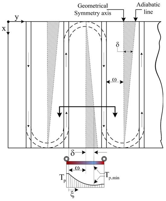
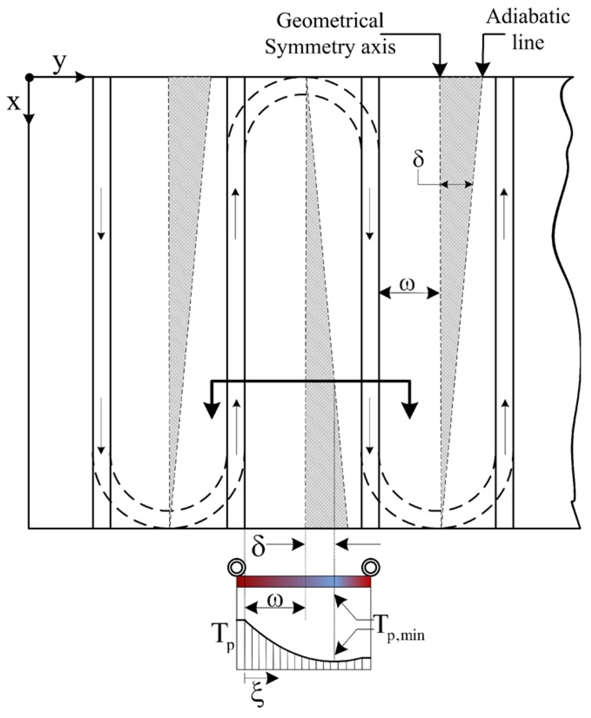
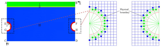
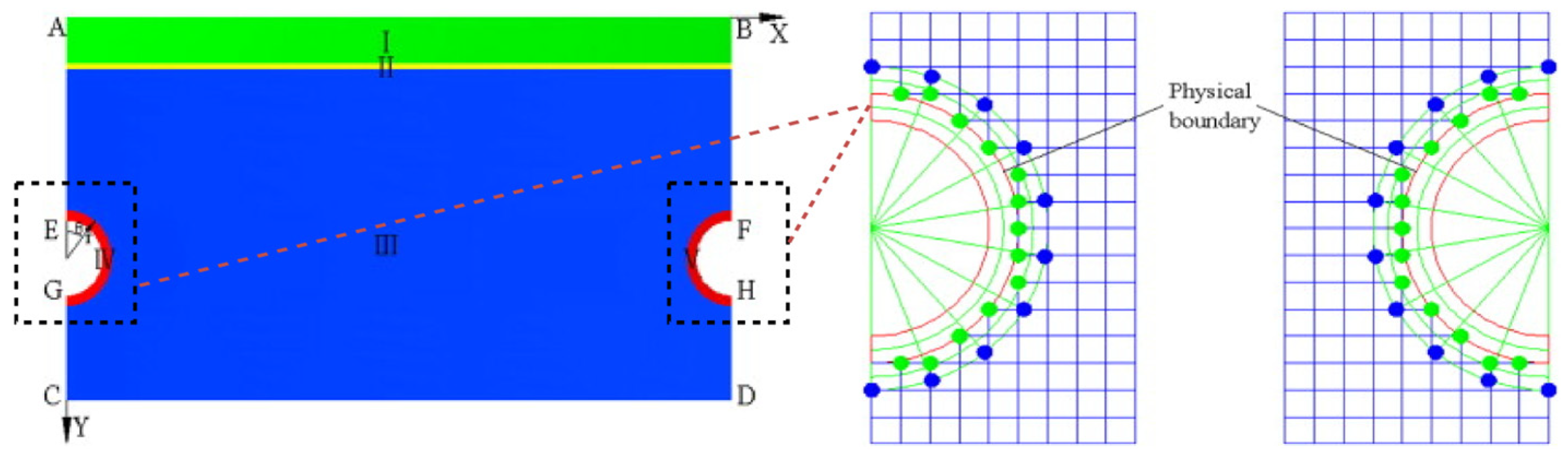
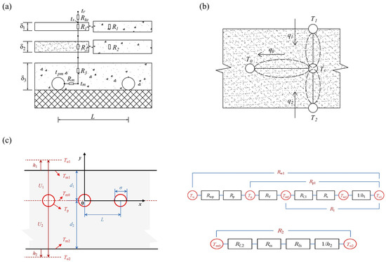
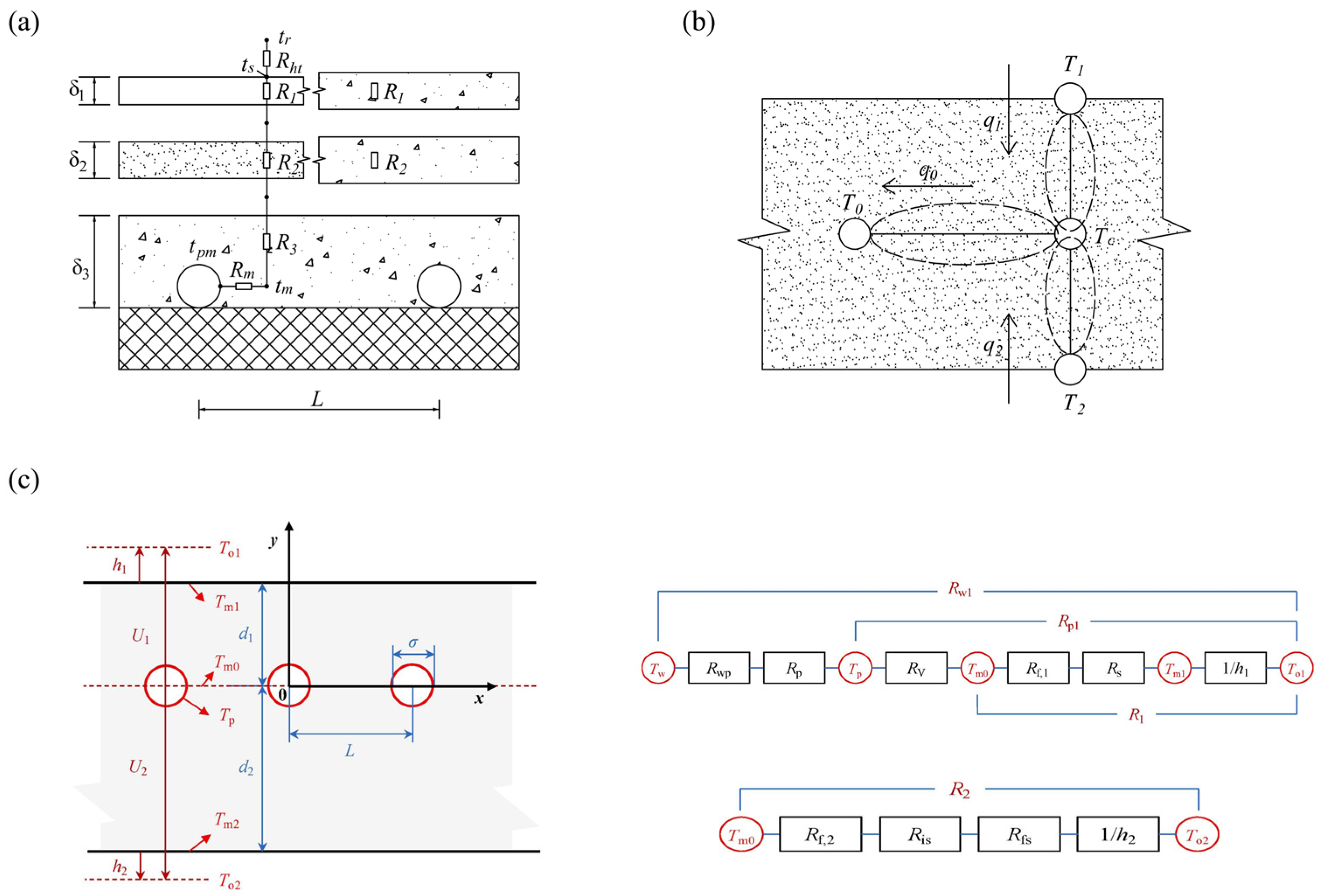
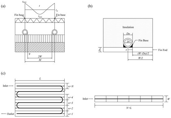
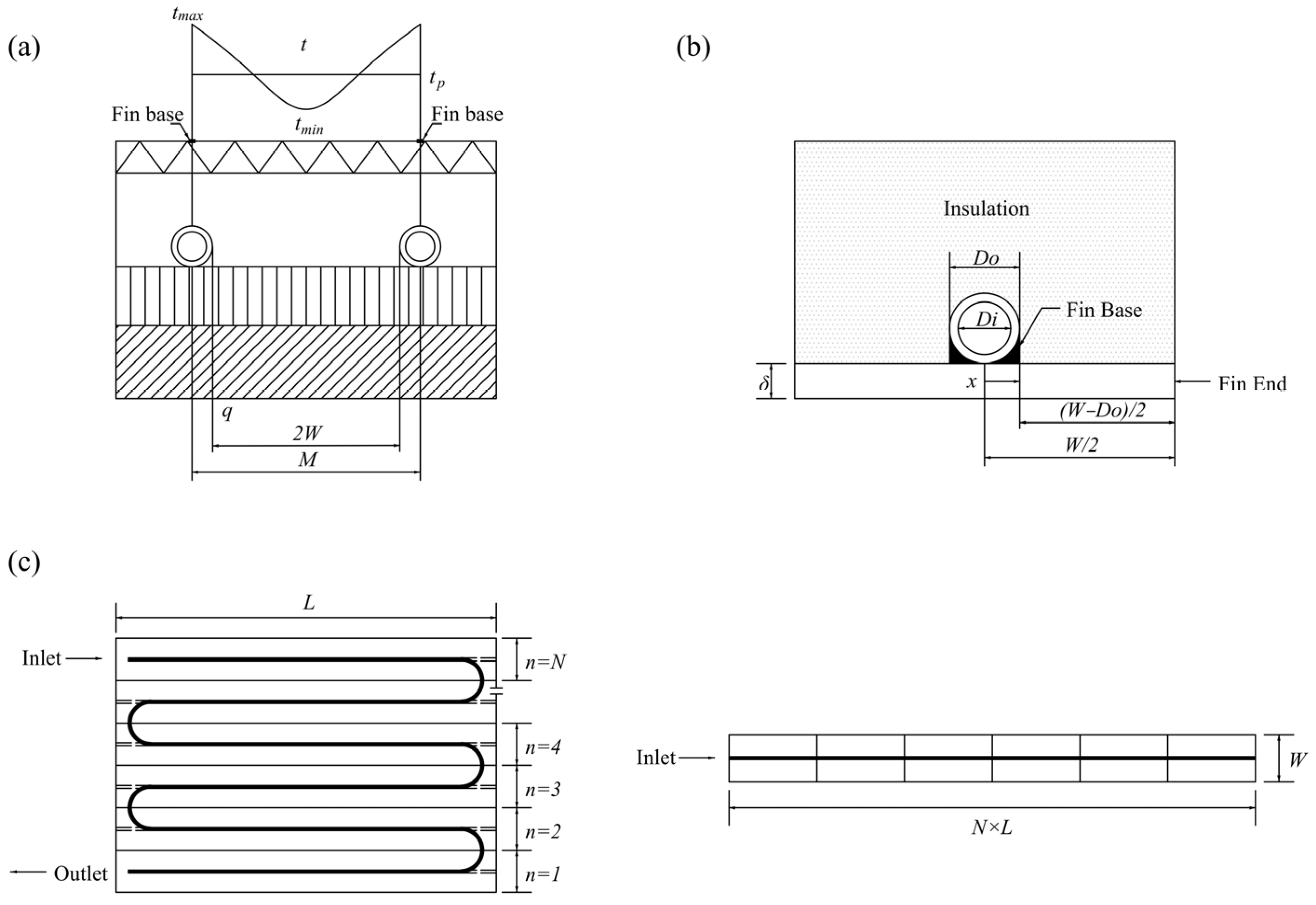

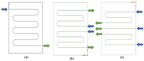
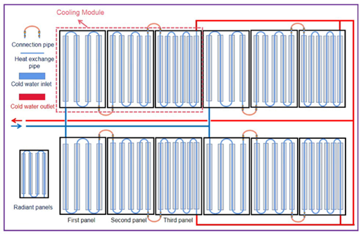
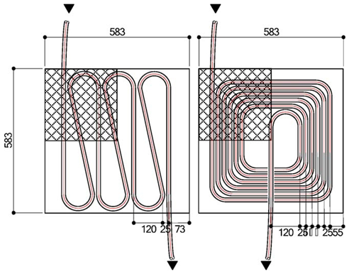
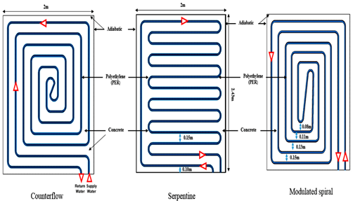
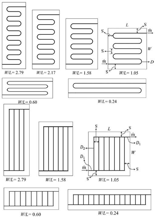
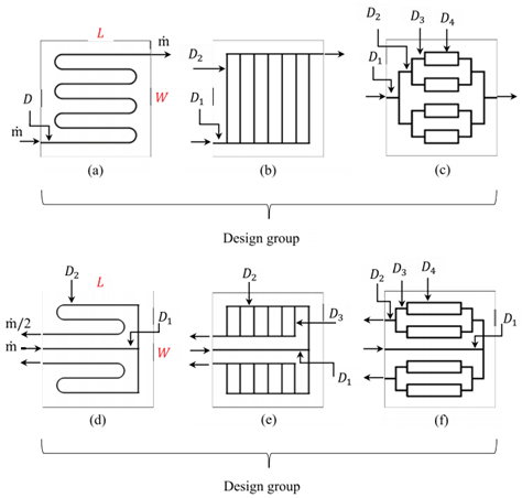
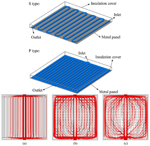
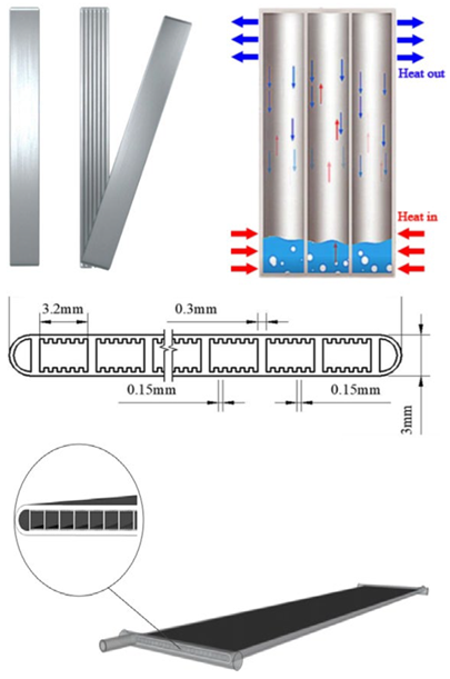
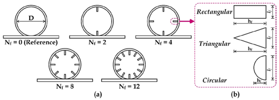
Disclaimer/Publisher’s Note: The statements, opinions and data contained in all publications are solely those of the individual author(s) and contributor(s) and not of MDPI and/or the editor(s). MDPI and/or the editor(s) disclaim responsibility for any injury to people or property resulting from any ideas, methods, instructions or products referred to in the content. |
© 2025 by the authors. Licensee MDPI, Basel, Switzerland. This article is an open access article distributed under the terms and conditions of the Creative Commons Attribution (CC BY) license (https://creativecommons.org/licenses/by/4.0/).