


Abstract
Cascaded H-bridge power quality improving device (PQID) has garnered extensive attention for its flexible electric energy conversion and fast voltage response. However, the failure rate of PQID is relatively high due to the use of large numbers of power electronic devices. This paper proposes a mechanical-switch based adaptive fault ride-through strategy for improving the operational stability and power supply reliability of PQID. According to the features of the topology and working principle of PQID, this paper summarized the types of internal faults and analyzed the characteristics of different types of faults. Based on the shortcomings of existing mechanical switches as a bypass method, corresponding adaptive fault ride-through strategies are proposed for different types of faults, and a comprehensive simulation test has been carried out. The results show that the proposed strategy can adaptively ride through unit faults and effectively improve the output waveform quality during the ride through time.
1. Introduction
As the proportion of renewable energy in the power system increases, many traditional distribution systems transfer towards cyber-physical multi-microgrids (MMGs) [1]. Line voltage stability is one of the key objectives for distribution systems [2]. The diversification trend of the distribution network load puts forward higher requirements for the reliability of the power supply [3]. From the perspective of the power supply company, prompt online assessment, Two-Stage Active and Reactive Power Coordinated Optimal dispatch can improve the line voltage quality of the power system [4]. From the perspective of load, power electronic device is a more appropriate solution. Especially in medium voltage and large capacity field, power quality improvement devices (PQID) with energy storage have become the high-priority solution in current industry [5]. The cascaded H-bridge (CHB) has the characteristics of modularity and redundancy [6]. It can output a medium-voltage voltage of 10 kV without a step-up transformer, suitable for medium-voltage large-capacity application scenarios.
Multiple H-bridge power units cascade the output of PQID. Due to the use of many power semiconductor devices, the failure rate is relatively high [7]. Due to the modularity of PQID, its main faults all occur inside the H-bridge power unit. According to statistics, the proportion of power semiconductor device failures accounts for 38% of the failure statistics of multilevel converters [8,9]. The faults of the power unit can be divided into two types: short-circuit and open-circuit faults. Short-circuit switch faults are fast-acting and destructive, as it commonly damages the switch [10]. Usually, the Insulated Gate Bipolar Transistor (IGBT) switch module integrates hardware short-circuit protection mechanism [11]. However, the characteristics of open circuit faults are complex and not obvious [12]. Most modular converters can operate with open-circuit faults, but the quality of the output waveforms during operation with faults will decrease [13]. In severe cases, it may lead to secondary faults or even a shutdown. Therefore, operation with faults should ensure stability and consider the quality of the output waveform.
The H-bridge power units of PQID are independent of each other due to their high degree of modularity. The research hotspots of cascaded H-bridge topology fault ride-through are mainly concentrated on the H-bridge unit [14]. An internal-switch based ride-through method without an additional contactor is proposed [15]. However, this method is only applicable to the failure condition of the H-bridge with a current bypass path. A fault-tolerant operation method based on redundant units is proposed [16]. After the failure occurs, the redundant unit is put into operation, and the faulty unit is removed. The original capacity of the system can be maintained, but the input of the cold-standby unit takes time and will cause transient waveform distortion [17]. The continuous operation of the hot standby unit will increase the conduction loss [18]. A general overview of fault-tolerant control for three-phase voltage-type converters is detailed in [19]. A fault-tolerant control method based on neutral point shift for cascaded H-bridges is proposed [20], which can maintain good waveform quality after a fault occurs. However, the capacity of the system and the average amplitude of the output voltage have decreased. A zero-sequence voltage injected based fault-tolerant control strategy has been proposed [21], which takes power balance into account, but harmonic distortion will increase during operation. A cascaded H-bridge fault-tolerant control scheme that simultaneously copes with open-circuit and short-circuit faults is proposed [22], increasing the balanced line voltage. However, its shortcomings are also apparent, and the fault scenarios that can be dealt with are minimal.
In order to overcome the shortcomings of the above technology, improve the operation stability and power supply reliability of PQID and improve the quality of the waveform during operation with faults, this paper proposed a mechanical switch based adaptive fault ride-through strategy for PQID. Compared with the previous fault response methods, the main advantages of the fault ride-through strategy proposed in this paper are as follows.
- (1)
- The proposed strategy uses mechanical switches as reliable bypass devices, which reduces the system cost.
- (2)
- The proposed voltage optimization method has the advantages of simplicity and self-adaptation. There is no need to change the control strategy after completing the fault ride-through process.
- (3)
- The best fault ride-through method can be selected according to the system operation and fault conditions. The proposed strategy is applicable to all voltage-controlled cascaded H-bridge topologies.
The rest of this paper is structured as follows. The topology of the PQID is described in Section 2. This paper analyzes the different fault characteristics of the H-bridge unit in Section 3. A mechanical-switches based adaptive fault ride-through strategy for multiple faults is presented in Section 4. Simulation results are presented in Section 5 to test the performances of the proposed strategies. The conclusions are drawn in Section 6.
2. PQID and Its Fault Ride-through
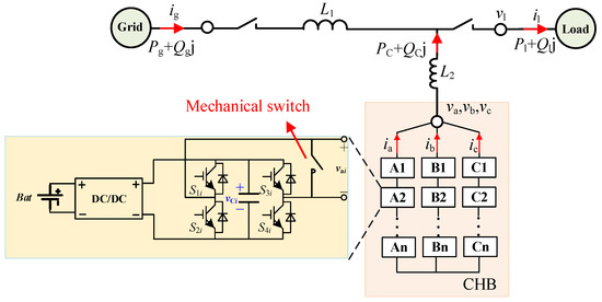
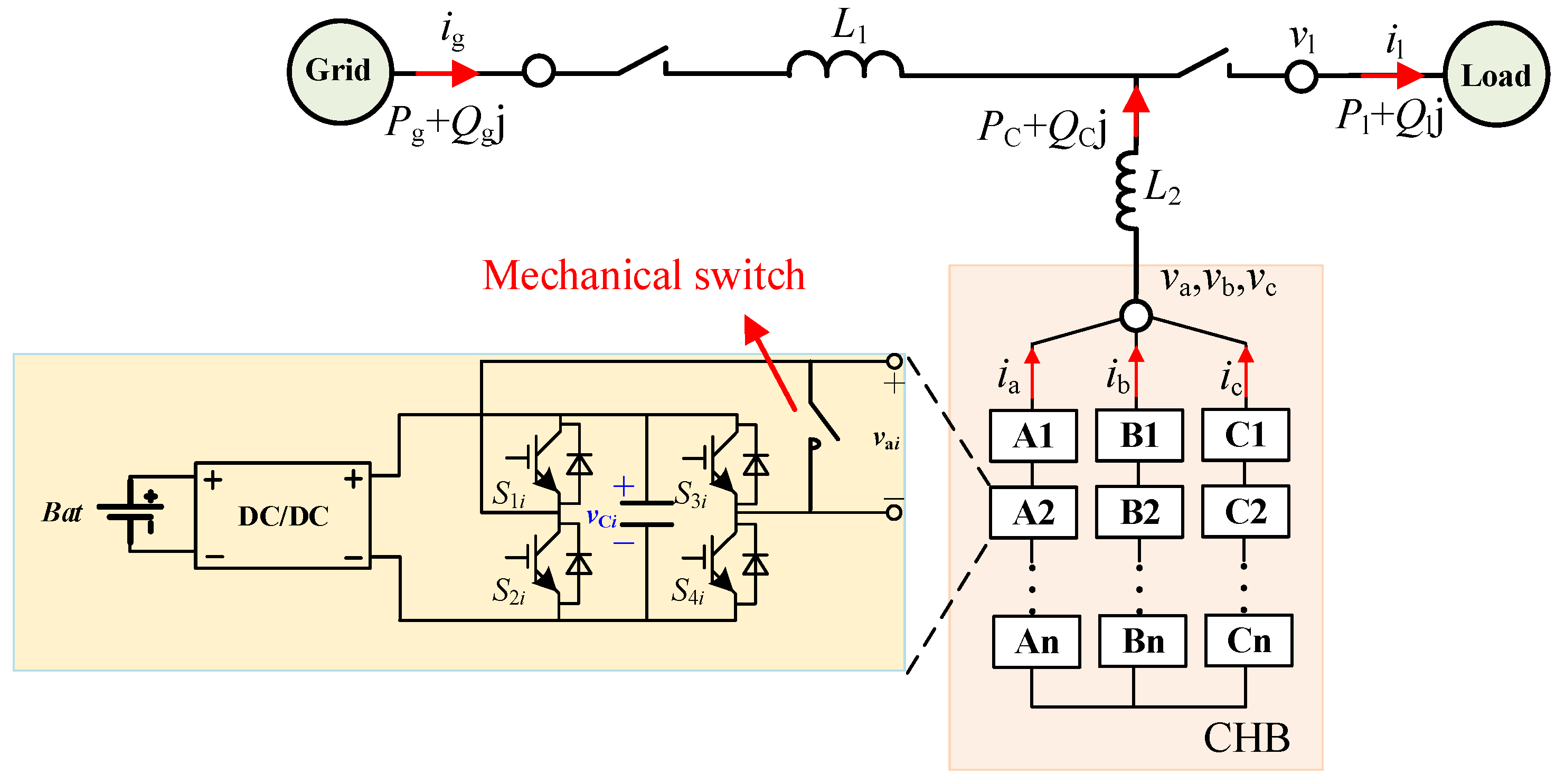
Figure 1 shows the topology of PQID. Each phase is cascaded by n H-bridge inverter units. The phase voltage vm is:
Figure 1.
The topology of PQID.
vmi is the output voltage of the power unit. Each unit in PQID has the same topology, and the Direct Current (DC) side of each unit is independent of the others, which makes it easy to achieve voltage balance. The cascaded H-bridge (CHB) can output medium voltage Alternating Current (AC) voltage without a transformer. If the modulation is reasonable, the operation of each power unit is symmetrical.
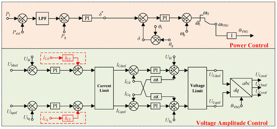
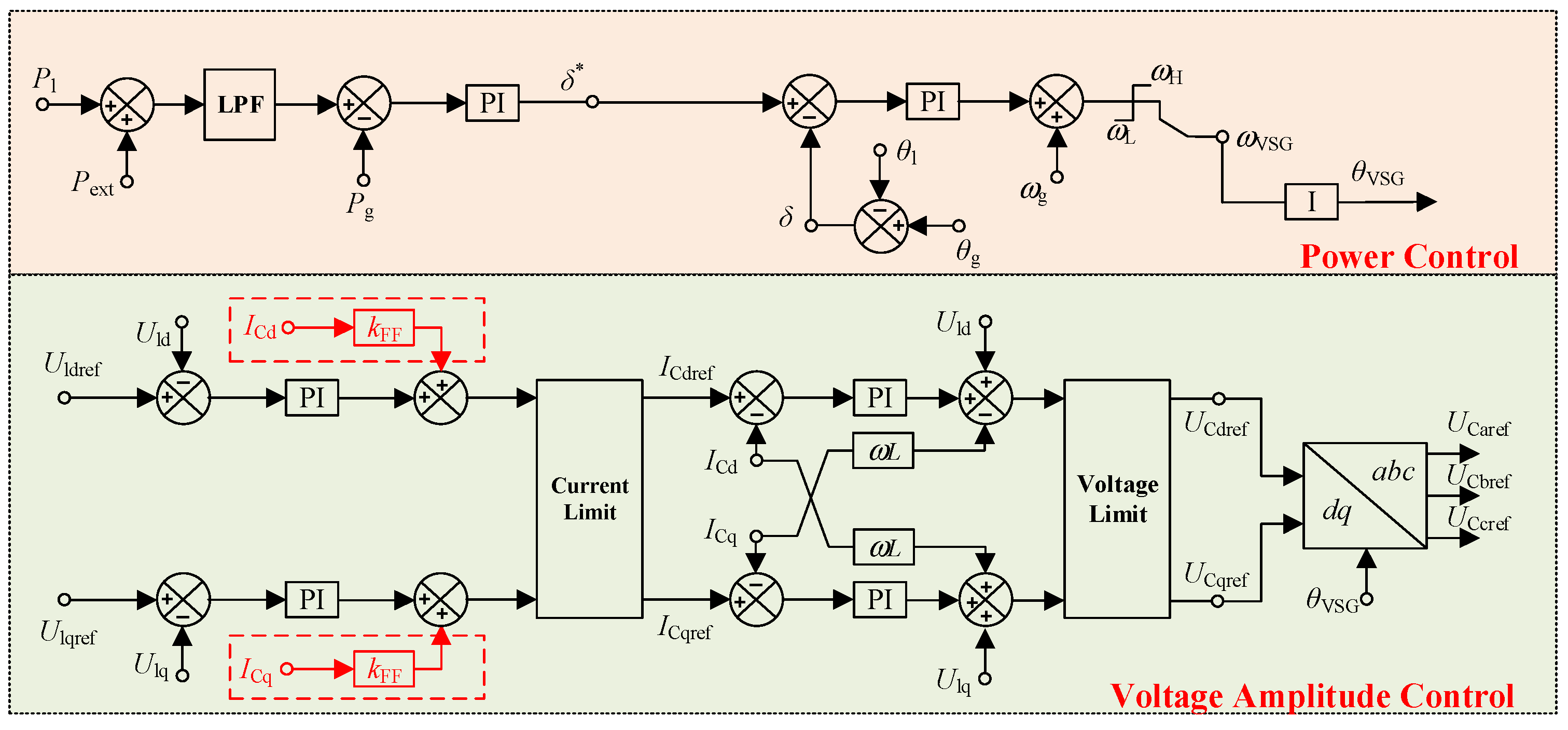
Figure 2 shows the voltage control strategy of PQID. This control strategy is divided into two parts: power control and voltage amplitude control.
Figure 2.
The topology of power unit.
(1) Power control is used to maintain the power balance of the system. Pl is the active power of the load, Pg is the active power of the grid side, and Pext is the output active power setting value of CHB (0 during normal operation). The relationship between Pg and phase angle difference of grid and load δ is:
where Ug is Root Mean Square (RMS) of grid voltage, Ul is RMS of load voltage, X1 is the impedance between grid and load. Based on the power difference between Pg and Pl, the reference value of δ∗ can be obtained through PI control. Adjusting the load voltage frequency can realize the tracking of δ to δ∗, and achieve the purpose of power control.
(2) The voltage amplitude control is used to maintain the stability of the load voltage Ul. Uldref = 1, Ulqref = 0. ICdref and ICqref are the reference value of the dq axis component of the CHBC output current. UCdref and UCqref are the reference value of the dq axis component of the CHBC output voltage. The CHBC three-phase modulation voltage is obtained through the inverse dq transformation.
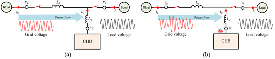
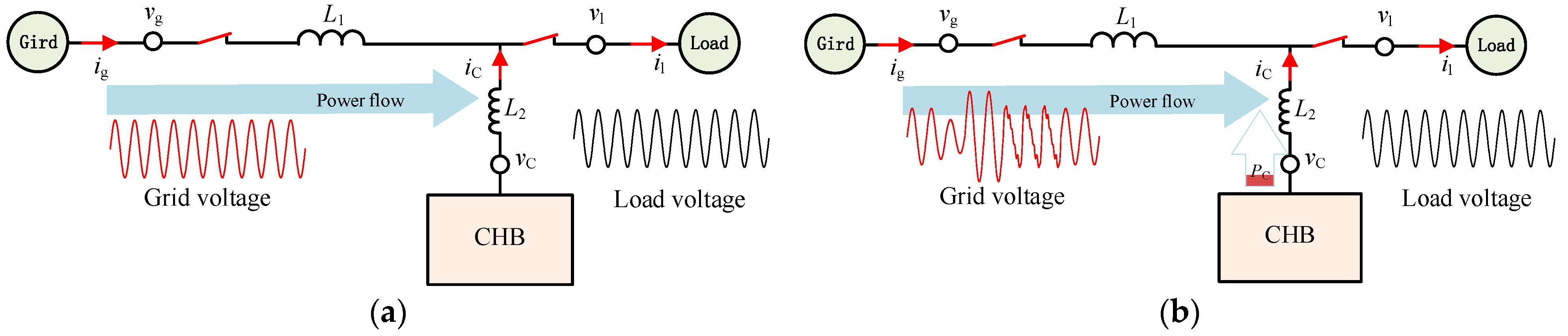
When vg is normal, the power flow is shown in Figure 3a. CHB does not output active power. When vg drops or is interrupted, the power flow is shown in Figure 3b. CHB output active power.
Figure 3.
Power flow of the PQID: the grid voltage is normal (a), the grid voltage is abnormal (b).
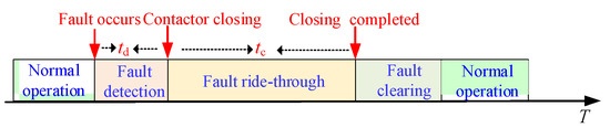
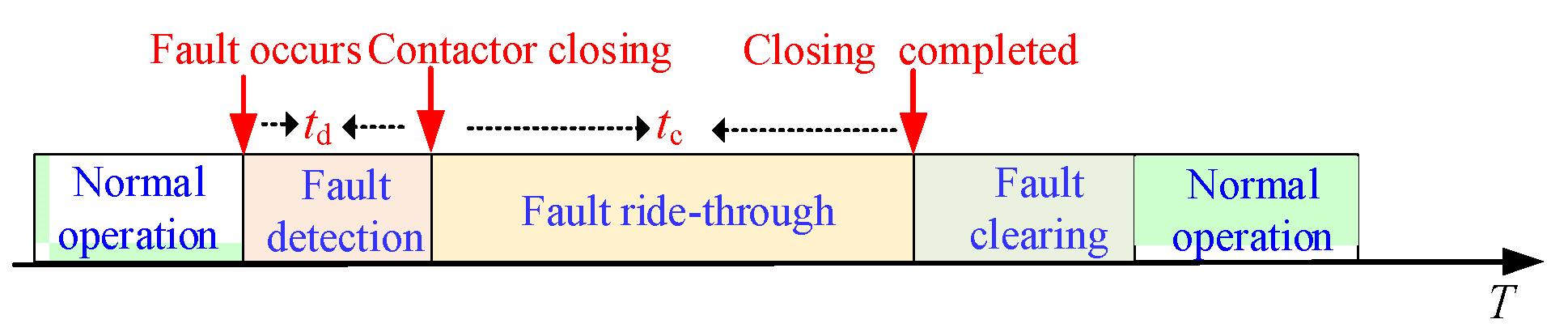
The stability of PQID is mainly affected by the power unit. The bypass switch of the power unit is a mechanical switch with a slow closing speed, and its closing time is 100–130 ms. The closing time is too long for the cascaded H-bridge system. Therefore, the system needs fault ride-through and voltage optimization during closing time. Figure 4 is the timeline.
Figure 4.
Timeline of expected PQID behavior during fault occurrence.
3. Power Unit Fault Analysis
Since the IGBT module integrates short-circuit protection, this article only discusses open-circuit faults. When the inverter unit is normal, the power unit can complete the fault ride-through process by internal bypass switches. Therefore, this section only analyzes the inverter unit fault. Inverter unit faults can be divided into controllable faults and uncontrollable faults.
3.1. Controllable Fault
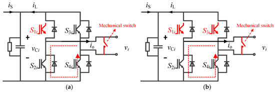
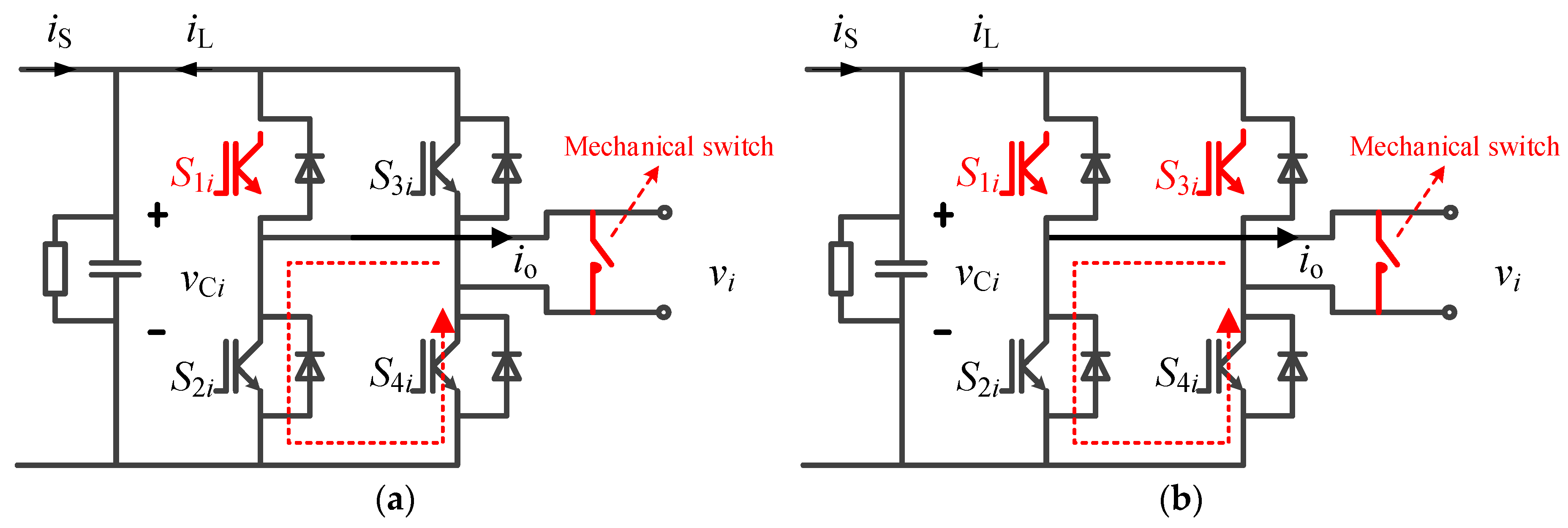
Figure 5 shows controllable faults, a common feature: a current bypass path shown by the dashed line. This article classifies this type of faults as controllable faults.
Figure 5.
Example of controllable faults: S1i open-circuit fault (a) and S1i, S3i open-circuit fault (b). There is an internal bypass current path.
The output voltage of the power unit during normal operation is:
where vCi is the capacitor voltage, S1i, S2i, S3i, S4i is the trigger signal state of switches. Figure 5a shows the open-circuit fault of S1i. io < 0, the current flows through the anti-parallel diode of S1i. io > 0, since the open circuit of S1i blocks the current path, the current will flow through the anti-parallel diode of S2i instead of the capacitor. The output voltage is:
where f1,i is the fault state of S1i. When an open circuit fault trigger in S1i, f1,i = 1. When S1i is normal, f1,i = 0. α is defined as:
According to Equation (4), it can be seen that IGBT open-circuit fault will destroy the symmetry of voltage and current. Because of the current bypass path existing, the method proposed in [12] can be used to isolate the faulty unit.
3.2. Uncontrollable Fault
When the power unit has multiple open-circuit switches, the current bypass path does not exist. This article classifies such faults as uncontrollable faults.
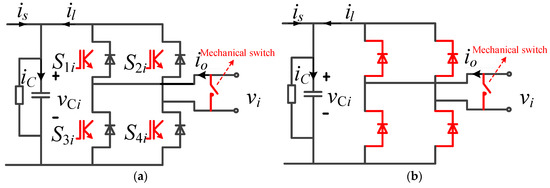
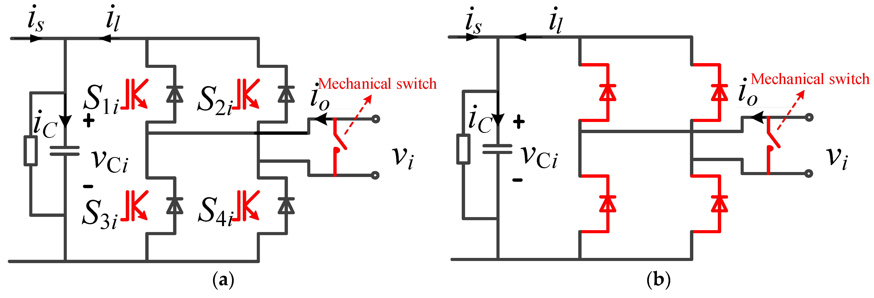
Figure 6 shows the most severe uncontrollable fault, all IGBTs in open-circuit condition. The current flows into the DC capacitor through the diode with the power transmitting in the reverse direction and capacitor charging. According to Equation (4) the unit output voltage of uncontrollable fault is obtained as:
where f2,i is the fault state of S2i, f3,i is the fault state of S3i, f4,i is the fault state of S4i.
Figure 6.
Example of uncontrollable faults: all IGBT open-circuit fault (a) and equivalent circuit (b). There is no internal bypass current path.
Power unit normal operation, the rectifier output current is > 0. An uncontrollable fault occurs, il > 0. The power is transferred from the inverter circuit to the capacitor in the reverse direction. Since the rectifier on the other side of the capacitor cannot transfer power in the reverse direction, is = 0. In a cycle, assuming that the average voltage of the capacitor is Uav, the active power consumed by the discharge resistor is U2av/R. Since the value of R is immense (typical value is 50–75 kΩ), the short-term power dissipation effect of the discharge resistance R on the power can be ignored. The voltage value ΔUC that rises in a cycle can be calculated.
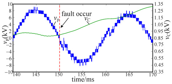
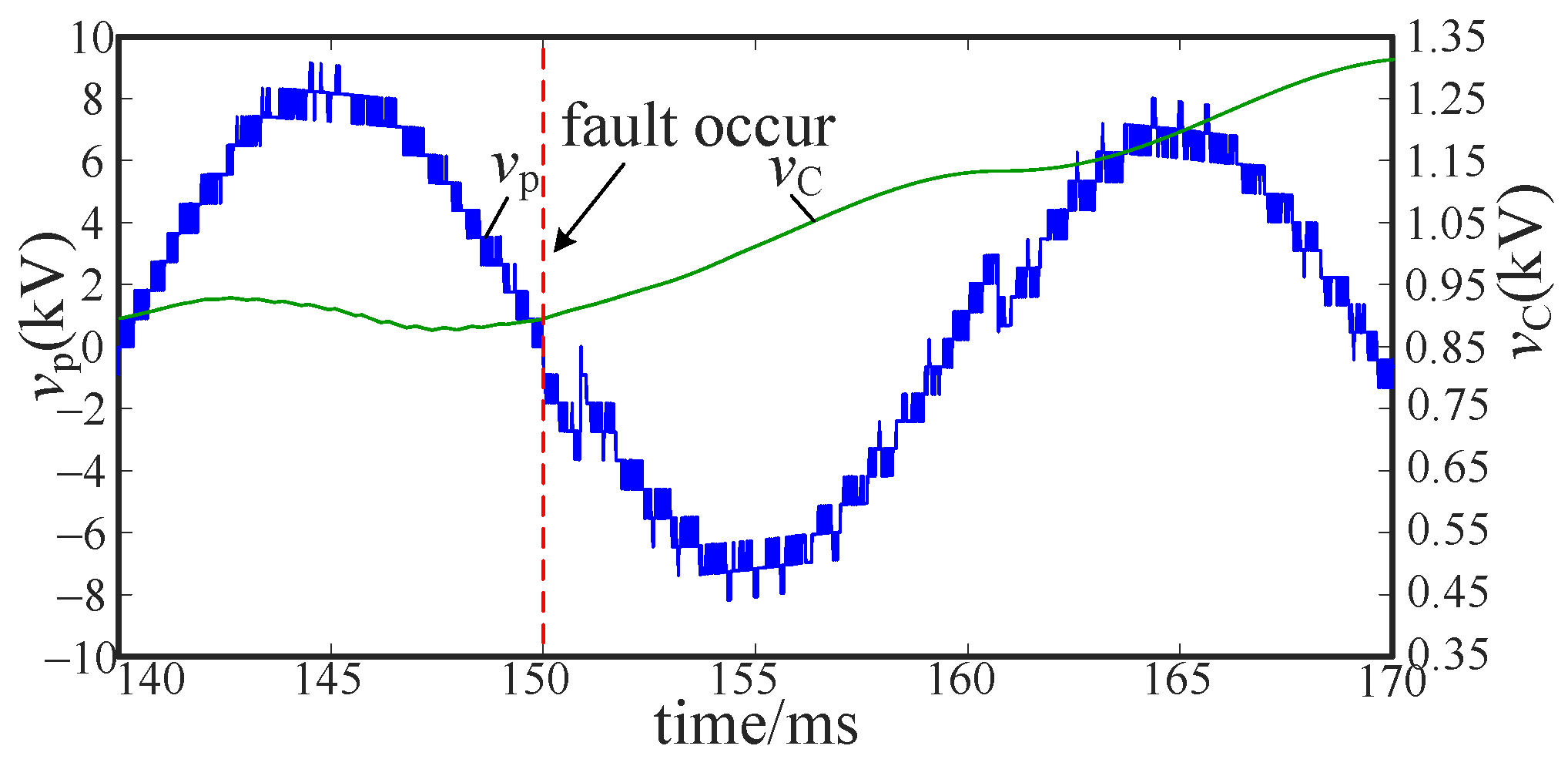
If C = 2520 µF, Im = 60 A, the rising voltage during a fault cycle is 0.152 kV, and the capacitor voltage reaches 0.758 kV in 50 ms after the fault occurs. Figure 7 shows the voltage and current changes in a cycle after the fault. Assuming the initial capacitor voltage UC0 is 0.9 kV. The capacitor voltage has reached 1.658 kV in 50 ms after the fault, which is very likely to exceed the withstand voltage of the IGBT. Therefore, when an uncontrollable fault occurs, bypass or other control strategies must be adopted to protect other normal switches and minimize the impact of the fault on the output voltage and current.
Figure 7.
Capacitor voltage and phase voltage in one cycle after the fault.
4. Fault Ride-through Strategy of PQID
4.1. Fault Ride-through Strategy under Controllable Faults
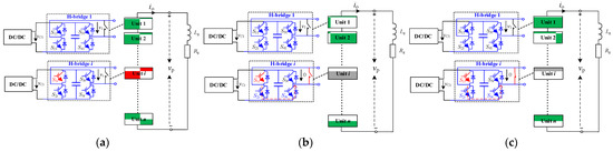
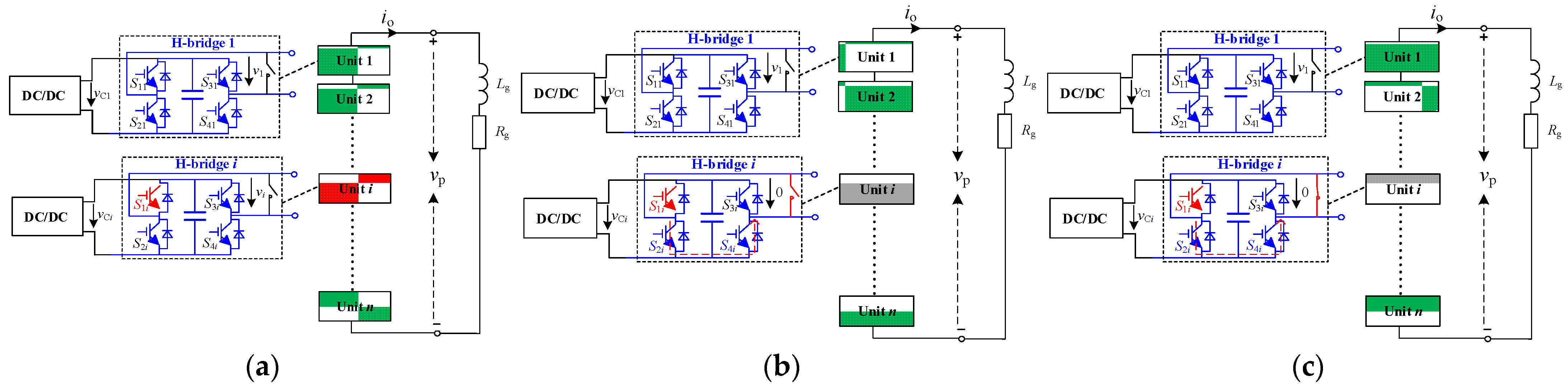
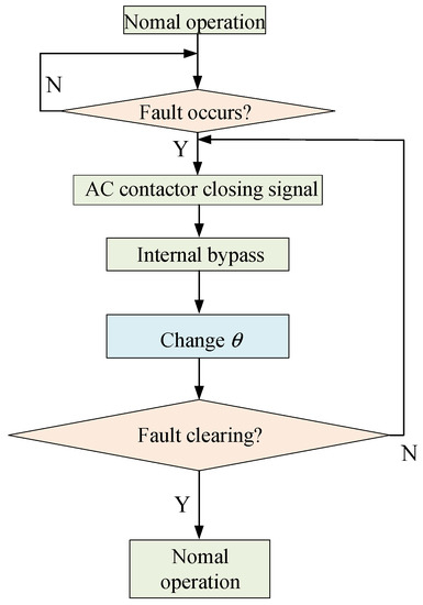
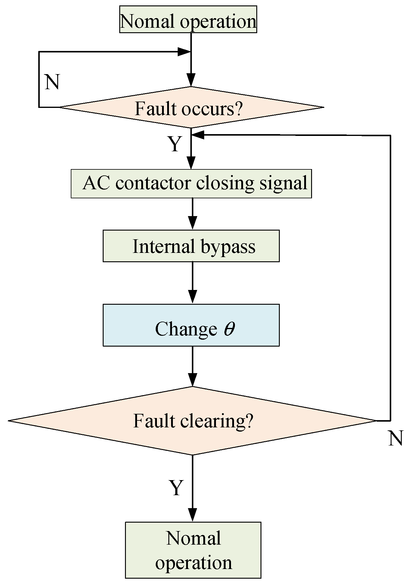
When a controllable fault occurs, the controllable IGBT in the unit is continuously turned on to form a current bypass path, and the unit output voltage decreases to 0. The phase shift angle is adjusted to compensate for the output voltage of the bypassed power unit. Figure 8 shows the state of the topology with a controllable failure. As shown in Figure 8a, the No. 1 IGBT of unit i has an open-circuit fault. After the fault detection, as shown in Figure 8b, the No. 3 and No. 4 IGBTs of the faulty unit are continuously turned on. The voltage of unit i remains at 0 in the fault ride-through state. After fault ride-through, as shown in Figure 8c, the mechanical switch of unit i is closed. Unit i enters the maintenance state. The systems of Figure 8b,c are kept running by the normal unit (green shaded). At this time, θ is calculated according to Equation (8).
Figure 8.
Example of controllable fault triggered in Unit i: fault triggered (a), self-bypass (b), mechanical switch closed (c).
Figure 9 shows the fault ride-through process of controllable faults.
Figure 9.
Flow chart of fault ride-through for controllable faults.
4.2. Fault Ride-through Strategy under Uncontrollable Faults
Due to the unavailable IGBT under the uncontrollable fault, it is necessary to use an external switch for fault ride-through. At present, some permanent magnet mechanisms can be closed within 3 ms, which are widely used in direct current transmission. The thyristor can be closed at the microsecond level. Generally, two thyristors are used in reverse parallel connection as a bypass device, but the power loss and requirements for the trigger power is relatively high. The above bypass scheme is high-cost when applied to CHBC with many units. In this section, an adaptive fault ride-through strategy based on mechanical switches under uncontrollable faults is proposed.
The output voltage of the power unit in Figure 6 is:
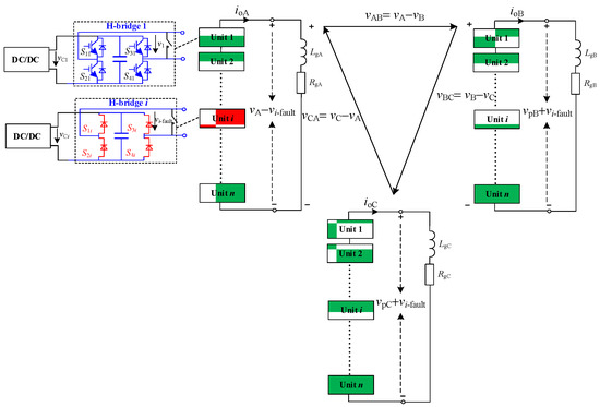
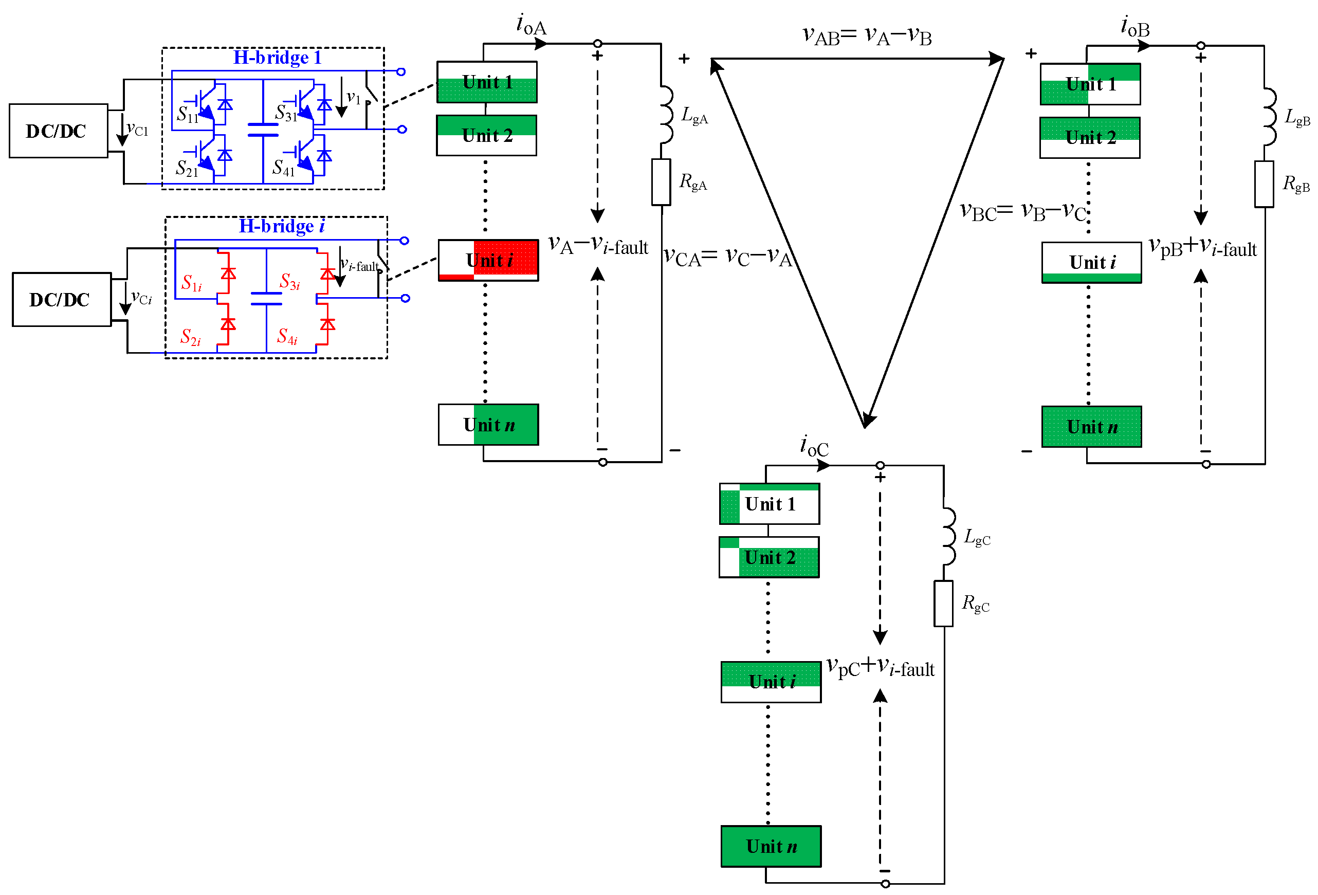
vi-fault is unrelated with Smi, which is mainly related to the current state.
Figure 10 shows the state of the topology with a controllable failure. As shown in Figure 10a, the most serious uncontrollable fault occurs in unit i: all IGBTs blocked. The equivalent circuit of the system is shown in Figure 10b. Unit i is already in an uncontrollable state.
Figure 10.
Example of uncontrollable fault triggered in Unit i: fault triggered (a), equivalent circuit (b).
The closing time tc of a mechanical contactor is generally 100–130 ms. After the contactor closing, vi-fault = 0, adjust the θ according to Equation (8). To allow PQID to pass the closing delay of tc, the control strategy needs to be adjusted to optimize the output voltage within tc.
Assuming that an uncontrollable fault occurs in unit x of phase A, the output voltage vA of phase A can be calculated.
There are two ways to optimize vA: intra-phase optimization and inter-phase optimization.
4.2.1. Intra-Phase Optimization
According to Equation (10), calculate the output voltage of the power unit vi-fault under an uncontrollable fault. The normal power units in phase are used to compensate vi-fault.
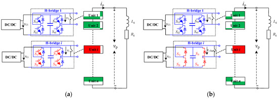
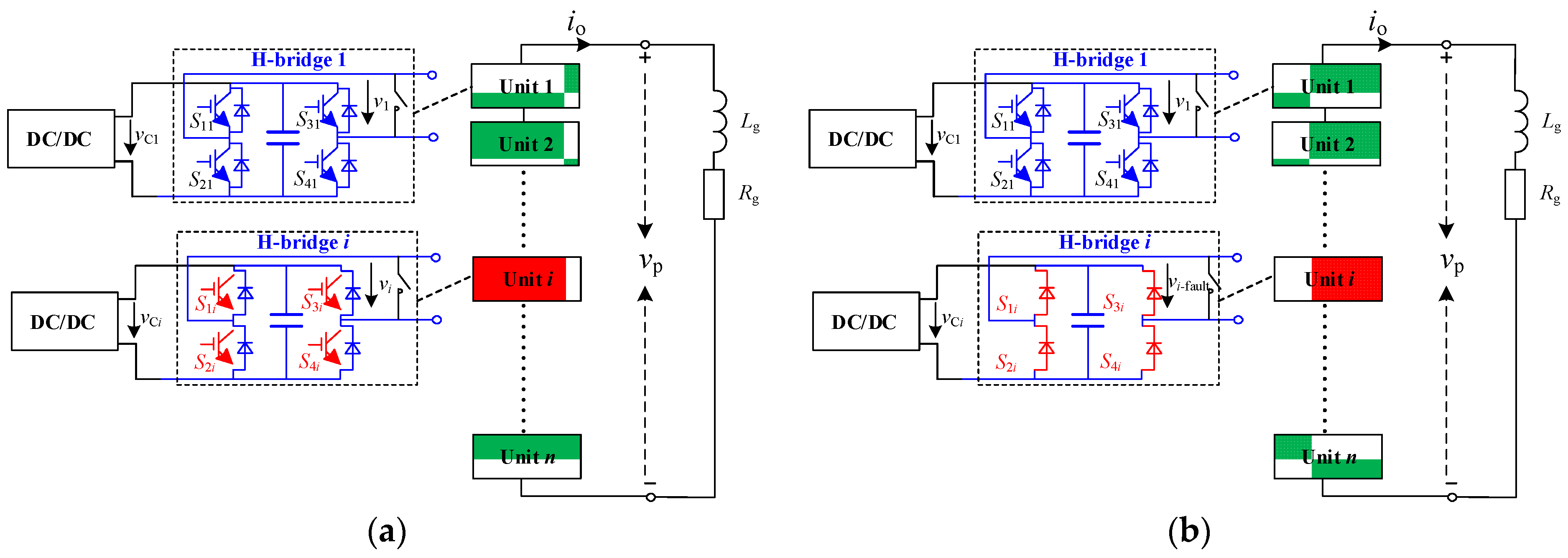
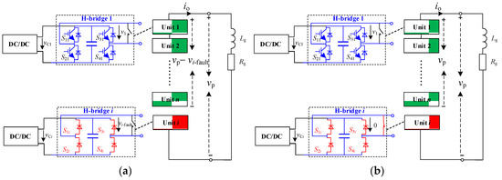
Figure 11 shows the topology state of the intra-phase optimization. As shown in Figure 11a, the mechanical switch is open during the closing time. The output voltage of normal units (shaded in green) is vp-vi-fault. The system output voltage is vp. As shown in Figure 11b, after the mechanical switch closed, vi-fault = 0. The output voltage of the system is equal to the sum of the output voltages of normal units.
Figure 11.
Intra-phase optimization: voltage optimization (a), mechanical switch closed (b).
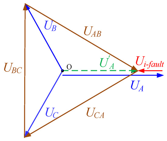
Figure 12 is the vector diagram of phase voltage optimization; U’A is the voltage of A phase before the fault occurs, which is modulated by all power units. UA is the voltage of A phase after the fault occurs, which is modulated by all normal units, and Ui-fault is the output voltage of the faulted unit. This method evenly distributes the task of compensating the voltage of the faulty unit to all normal power units in the phase, which is suitable for working conditions with low modulation.
Figure 12.
Intra-phase optimized voltage vector diagram.
4.2.2. Inter-Phase Optimization
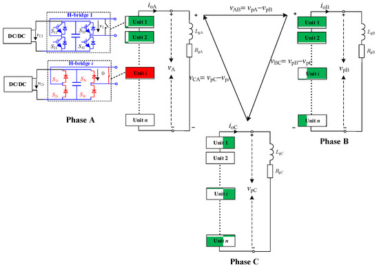
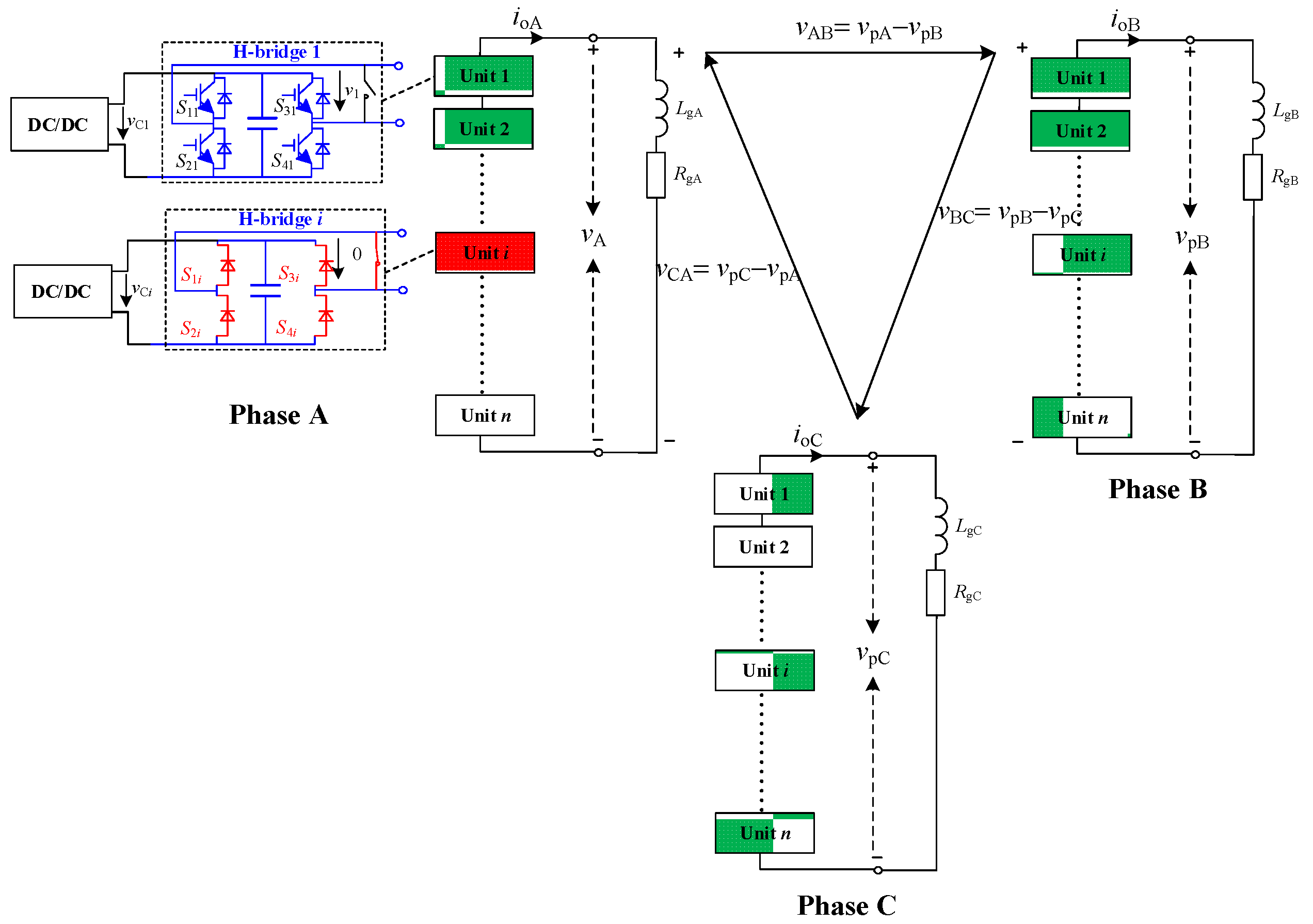
Unlike the intra-phase optimization, the inter-phase optimization does not optimize the phase voltage but directly optimizes the line voltage. Figure 13 shows the topology state of intra-phase optimization. The sum of the normal units’ output voltages of phase A is vpA. The output voltages of phase B and phase C are increased by vi-fault than normal. It can be seen from the figure that the line voltage can remain normal.
Figure 13.
Inter-phase optimization.
Figure 14 shows the topology state after the mechanical switch closed, vi-fault = 0. The system can keep the line voltage stable without adjusting the control strategy.
Figure 14.
Inter-phase optimization: mechanical switch closing.
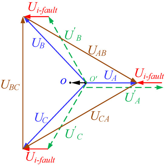
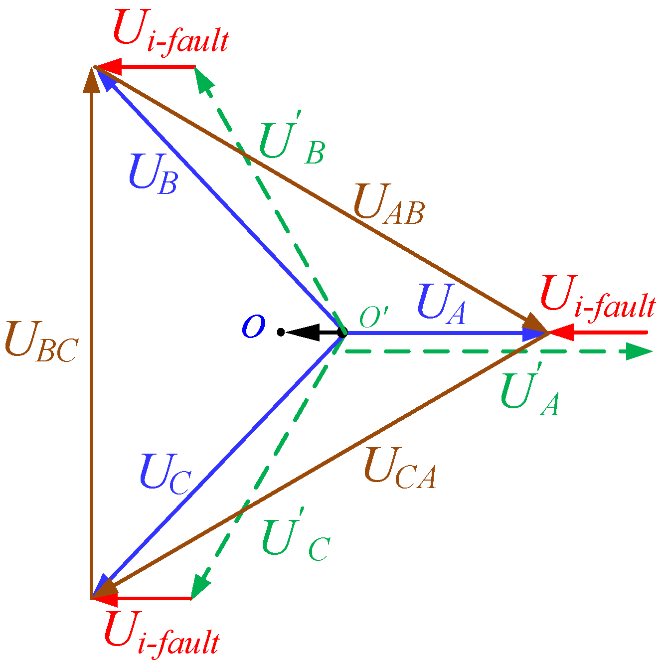
Figure 15 is the voltage vector diagram of the phase-to-phase voltage optimization. U’A, U’B, U’C are the three-phase voltages before the fault occurs. UA, UB, UC are the three-phase voltages after the fault occurs. Both UB and UC are superimposed with Ui-fault, and the neutral point is dynamically shifted from o’ to o. This method ensures the stability of the line voltage by superimposing the fault voltage on the phase voltage. Due to the angular difference between the fault voltage vector and the original phase voltage vector, the requirement on the system modulation ratio is lower.
Figure 15.
Inter-phase optimized voltage vector diagram.
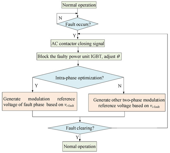
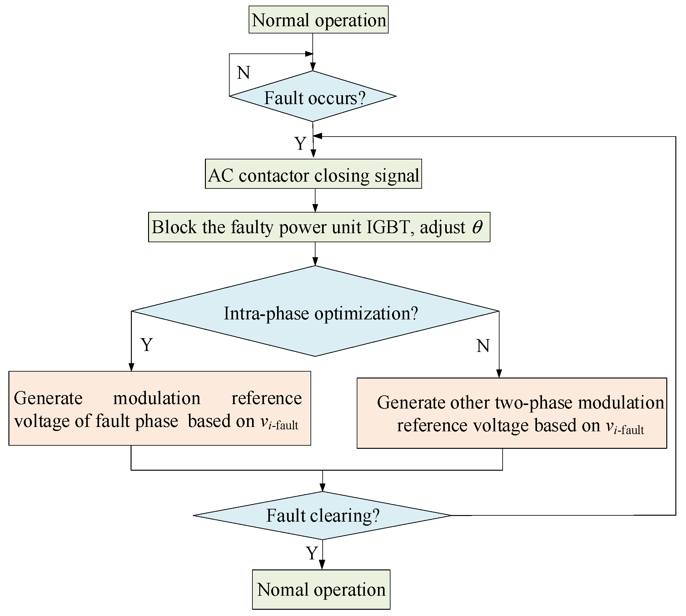
Comparing Figure 12 and Figure 15, it can be seen that the inter-phase optimization is equivalent to the neutral point shifted by vi-fault. The fault ride-through process under uncontrollable faults is shown in Figure 16.
Figure 16.
Flow chart of fault ride-through for uncontrollable faults.
5. Simulation and Verification
In this section, a PQID model is built in PSCAD/EMTDC (Manitoba Hydro International Ltd., Manitoba, Canada) to verify the proposed fault ride-through strategy. Table 1 shows the simulation parameters.
Table 1.
Simulation parameters.
5.1. Controllable Fault Simulation
The simulation conditions are set as follows. Figure 17 is the timeline of controllable fault simulation. The fault occurs in 150 ms. The fault detection time is 3 ms, and the mechanical switch closing time is 130 ms.
Figure 17.
Timeline of controllable fault simulation.
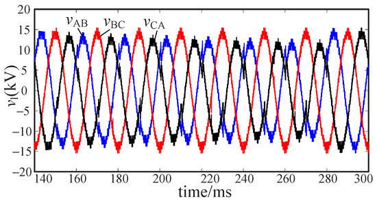
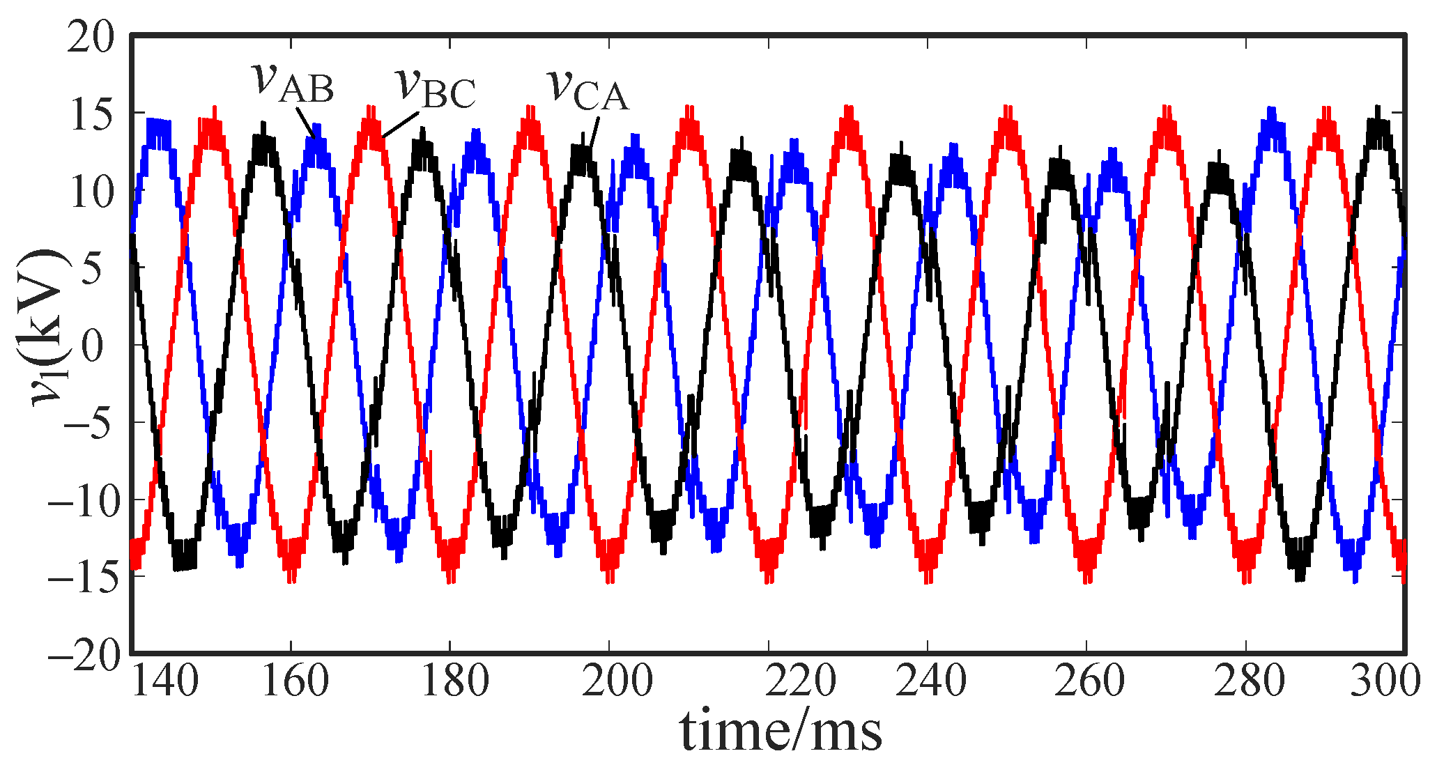
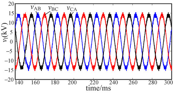
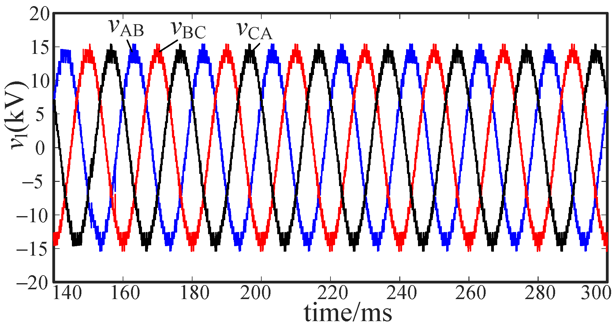
In medium voltage distribution networks, line voltage is usually used to assess voltage quality. Figure 18 shows the output line voltage without fault ride-through strategy. Figure 19 shows the output line voltage with fault ride-through strategy. The quality of the voltage waveform in Figure 19 is significantly better than that in Figure 18. The fault ride-through strategy proposed in this paper can significantly improve the voltage quality degradation caused by controllable faults.
Figure 18.
Line voltage without fault ride-through strategy.
Figure 19.
Line voltage with fault ride-through strategy.
5.2. Uncontrollable Fault Simulation
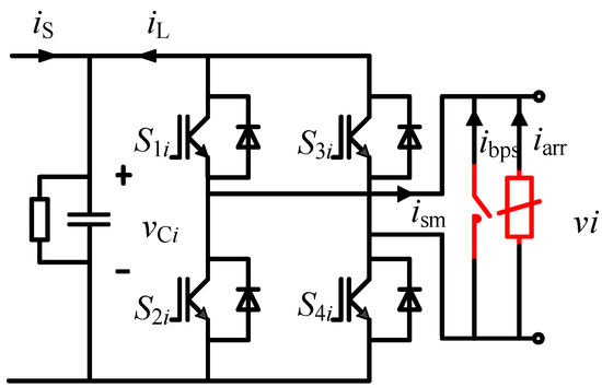
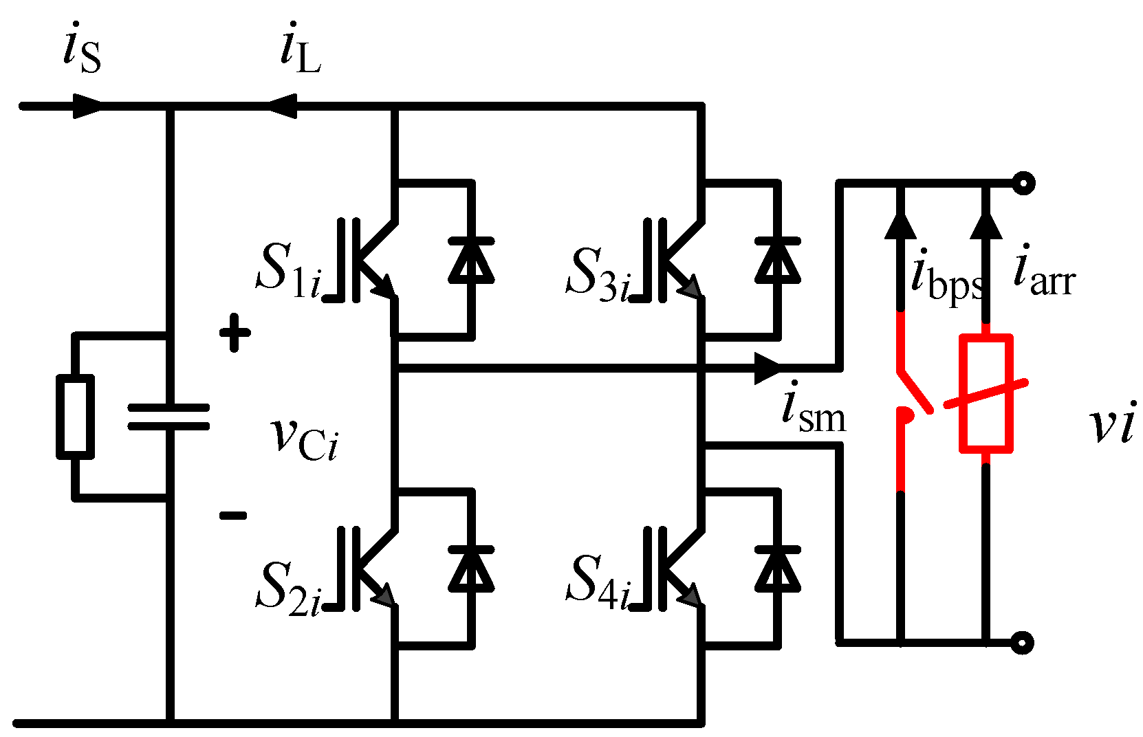
Figure 20 shows the H-bridge module topology of the simulation model. The H-bridge output port is connected in parallel with a lightning arrester and a mechanical switch. The mechanical switch performs as a reliable bypass. Lightning arresters are used to absorb excess energy. Figure 21 is the timeline of uncontrollable fault simulation. The fault occurs in 150 ms. The fault detection time is 3 ms, and the mechanical switch closing time is 130 ms.
Figure 20.
H-bridge topology of uncontrollable fault simulation.
Figure 21.
Timeline of uncontrollable fault simulation.
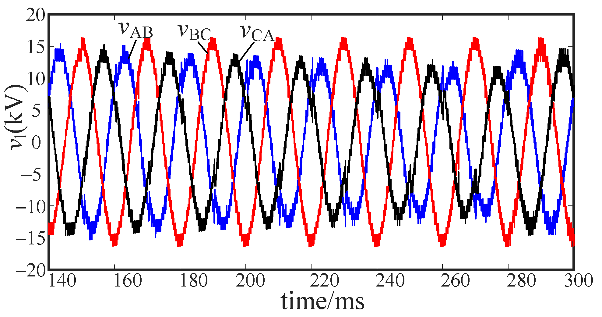
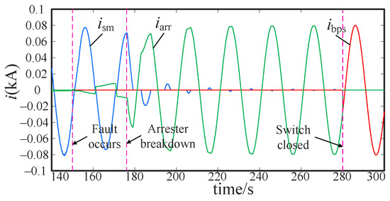
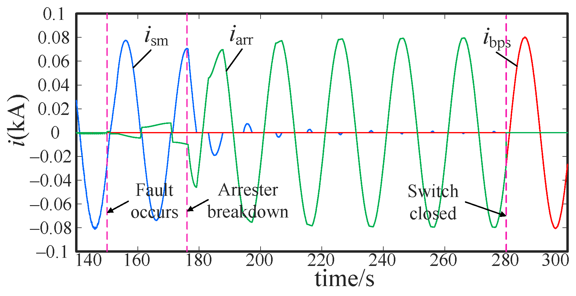
Figure 22 shows the output line voltage without fault ride-through strategy. It can be seen that the line voltage quality has dropped seriously. Figure 23 is the port current of the power unit. The lightning arrester breaks down before 180 ms to absorb the excess power of the power unit. The arrester actively breaks down to prevent overcurrent. The mechanical switch is closed at 280 ms, and the arrester current is 0.
Figure 22.
Line voltage without fault ride-through strategy.
Figure 23.
Current of power unit port.
5.2.1. Intra-Phase Optimization
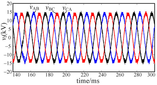
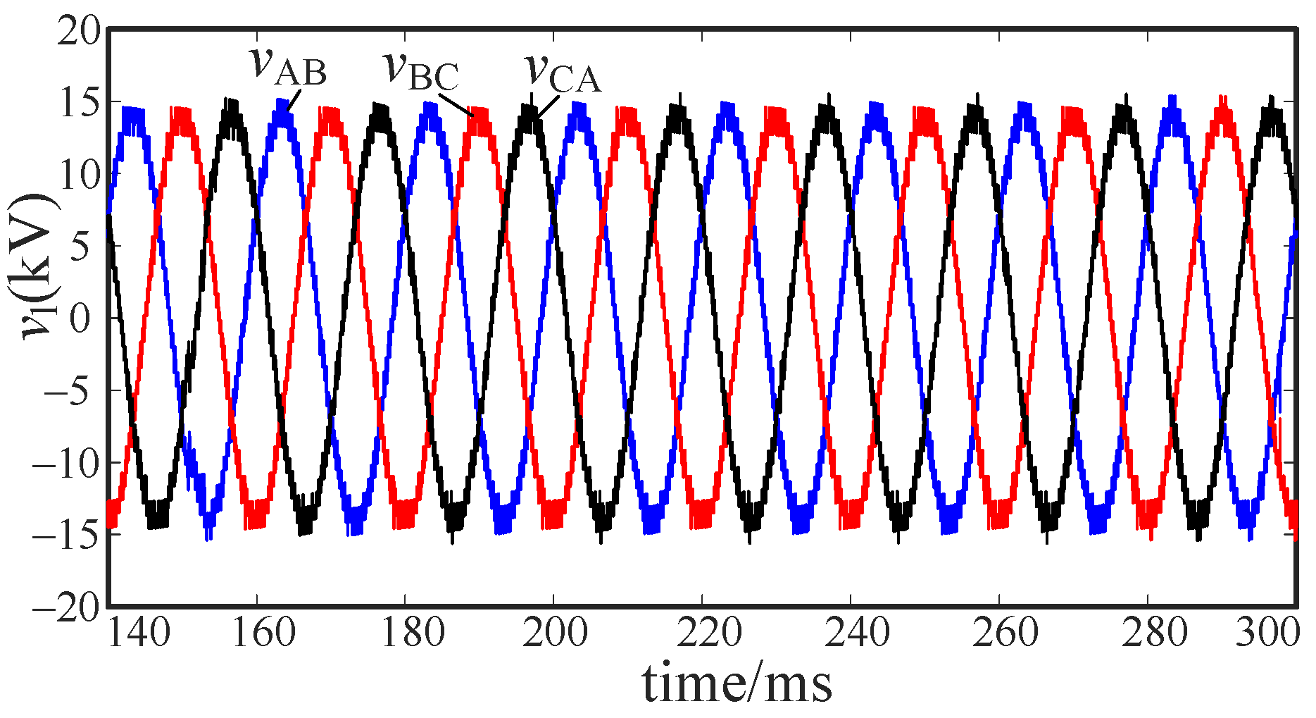
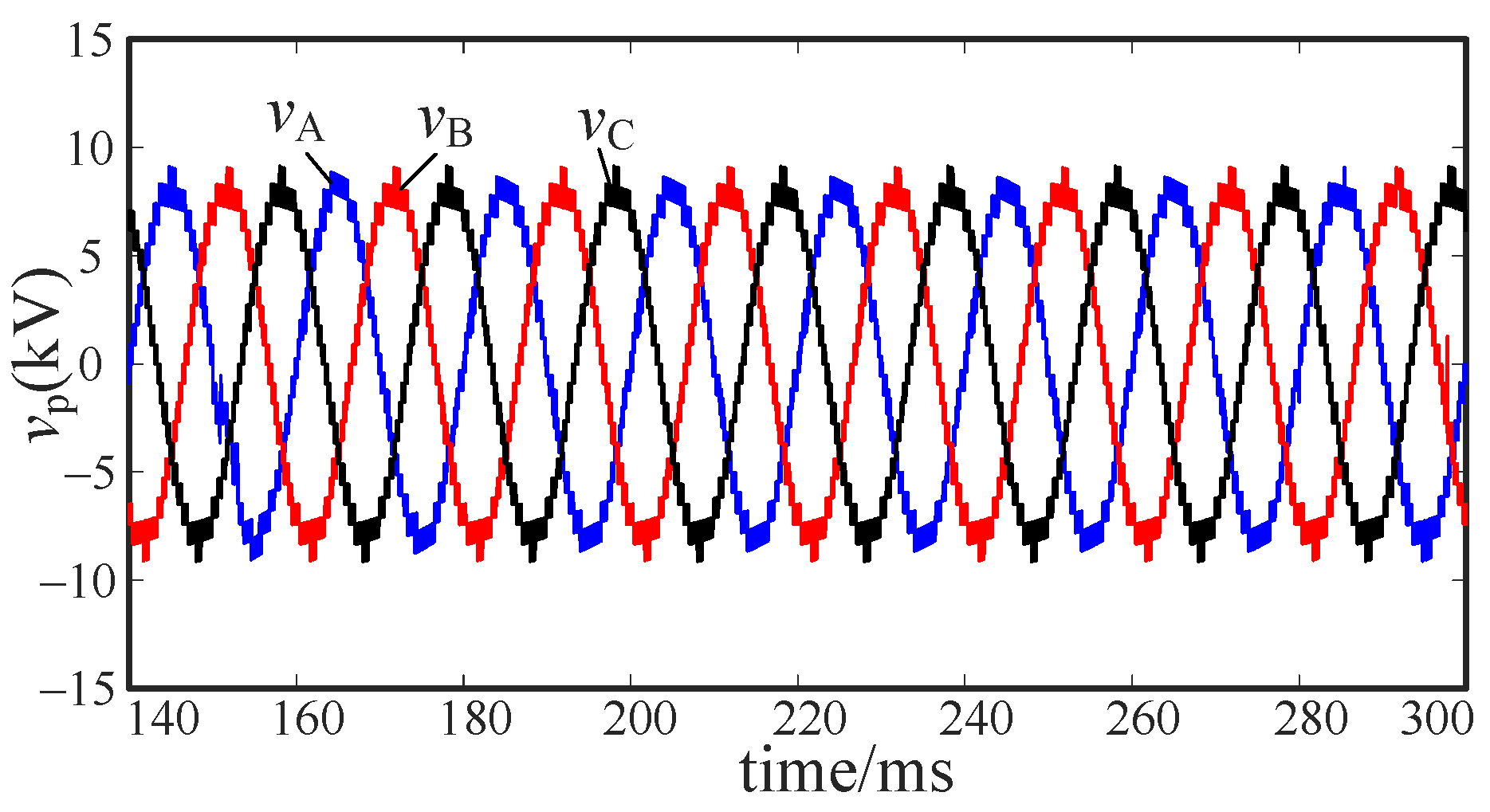
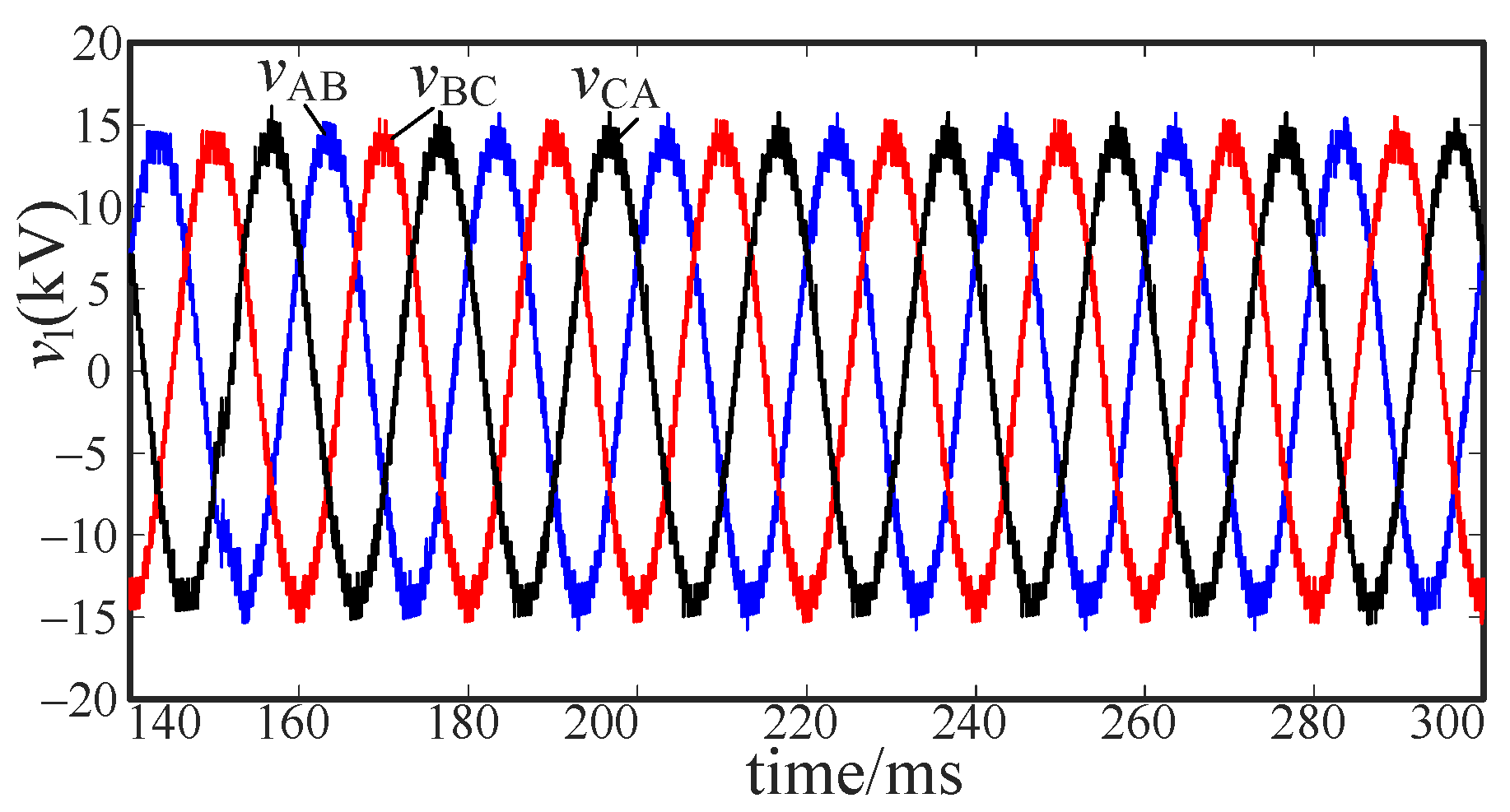
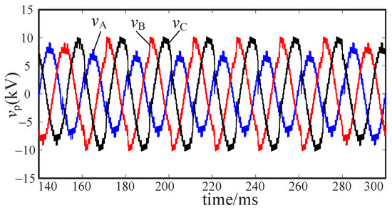
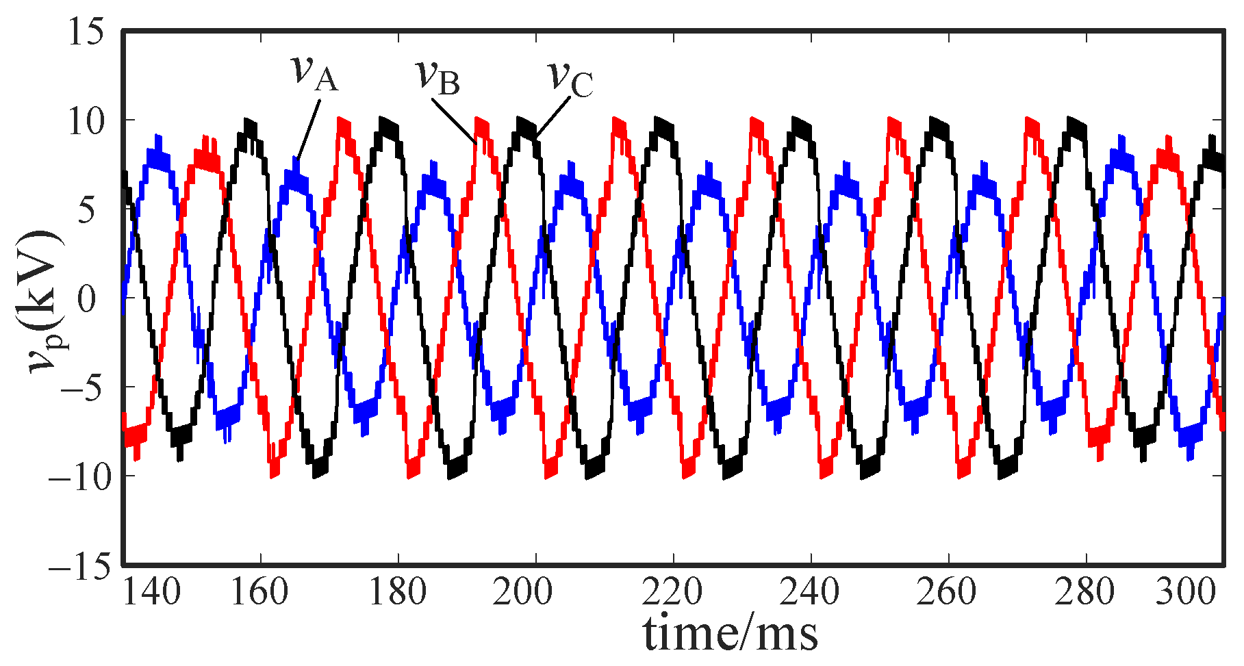
Figure 24 is the output line voltage with intra-phase optimization. The quality of the voltage waveform in Figure 24 is significantly better than that in Figure 22. Figure 25 is the phase voltage. As the figure shows, intra-phase optimization achieves voltage balance by compensating the phase voltage.
Figure 24.
Line voltage with fault ride-through strategy.
Figure 25.
Phase voltage with fault ride-through strategy.
5.2.2. Inter-Phase Optimization
Figure 26 is the output line voltage with inter-phase optimization. The quality of the voltage waveform in Figure 26 is significantly better than that in Figure 22. Figure 27 is the phase voltage. As the figure shows, inter-phase optimization achieves voltage balance by compensating the line voltage.
Figure 26.
Line voltage with fault ride-through strategy.
Figure 27.
Phase voltage with fault ride-through strategy.
5.3. Voltage Stability Analysis
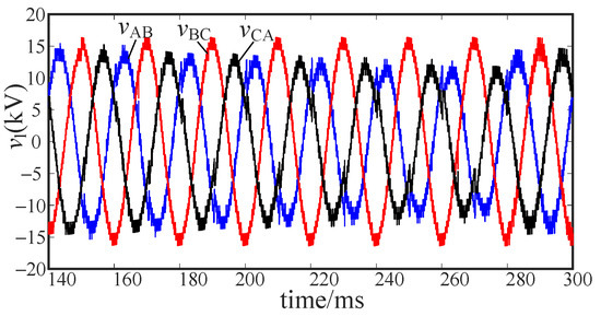
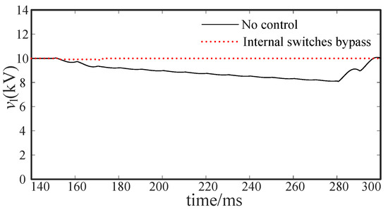
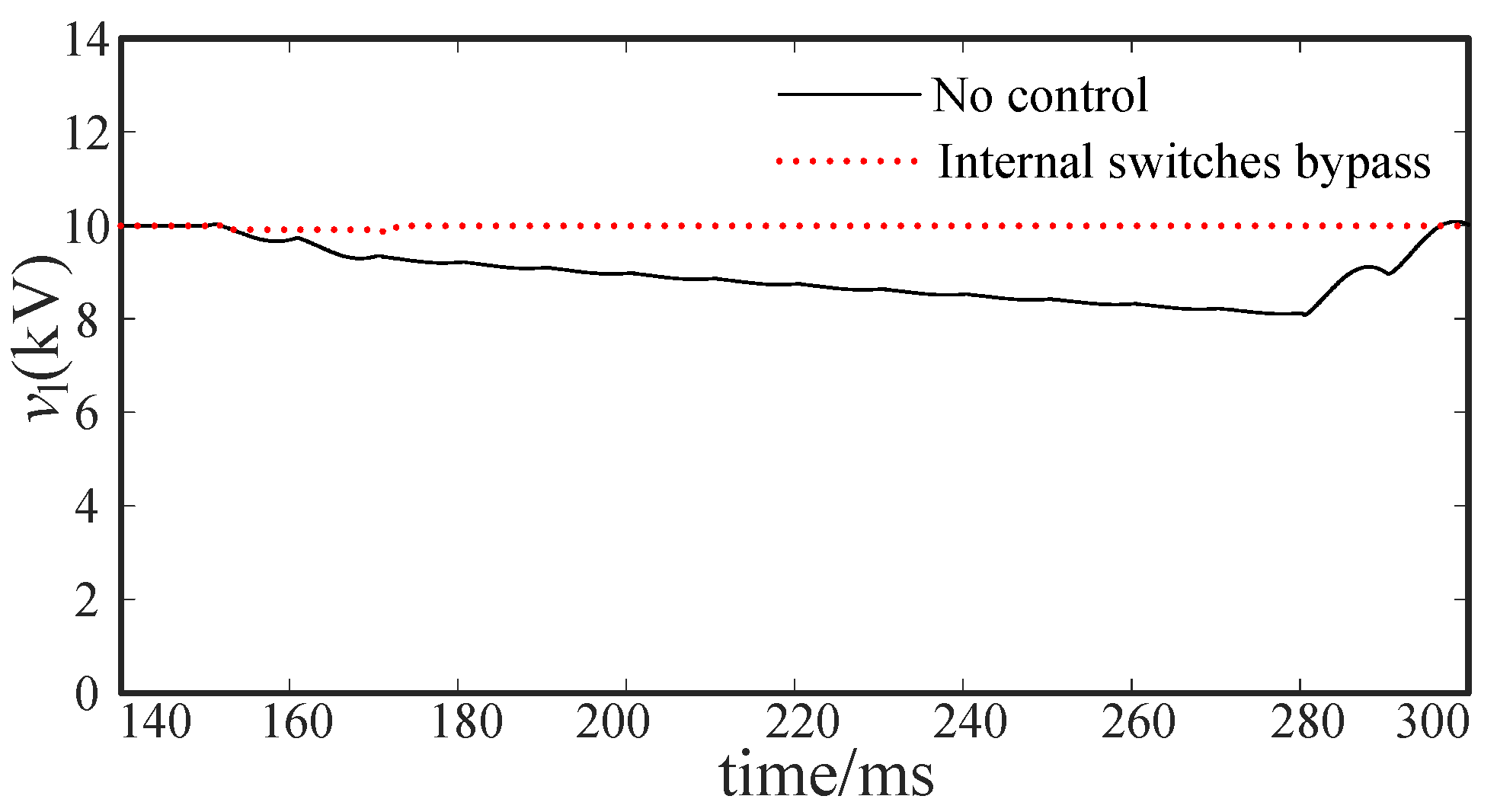
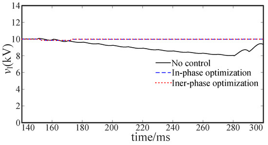
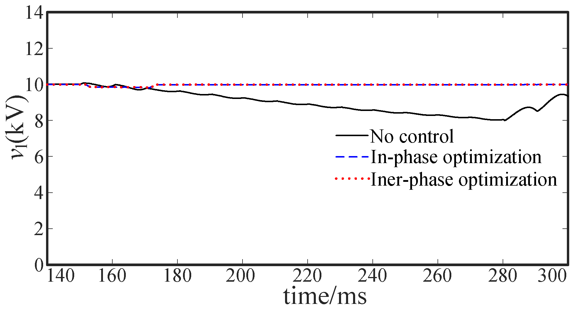
This section mainly analyzes the stability of the line voltage vAB, which is characterized by amplitude and harmonics. Figure 28 and Figure 29 are the voltage amplitude. Voltage amplitude voltage with the fault ride-through strategy is closer to 10 kV than that without fault ride-through strategy. As shown Figure 28 and Figure 29, The voltage amplitude represented by the solid line is close to 8 kV, which is already lower than the national standard. The fault ride-through strategy proposed in this paper can effectively maintain the line voltage amplitude during the fault.
Figure 28.
Amplitude of vAB of controllable failure.
Figure 29.
Amplitude of vAB of uncontrollable failure.
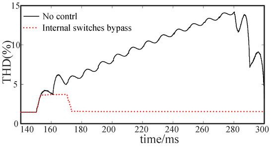
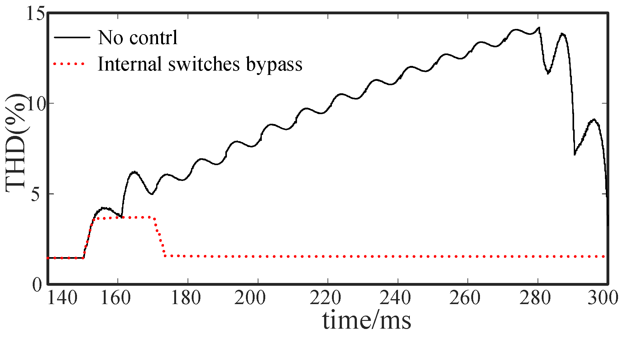
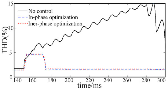
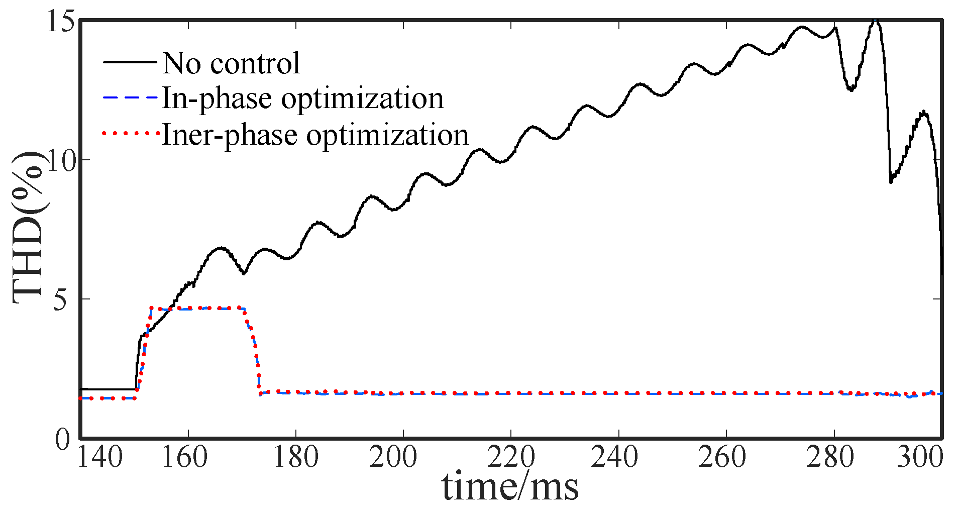
Figure 30 and Figure 31 are total harmonic distortion (THD). Due to the existence of the fault detection delay, the THD with the fault ride-through strategy will rise briefly, but the rise will not exceed 4%. However, THD without a fault ride-through strategy will continue to rise sharply. As shown in Figure 31, the THD represented by the solid line has exceeded the national standard. The fault ride-through strategy proposed in this paper can effectively prevent line voltage distortion.
Figure 30.
THD of vAB of controllable failure.
Figure 31.
THD of vAB of uncontrollable failure.
5.4. Reliability Analysis of Fault Ride-through Strategy
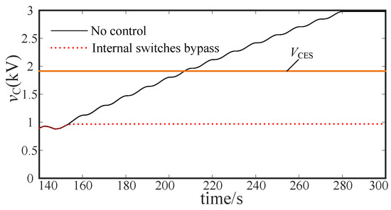
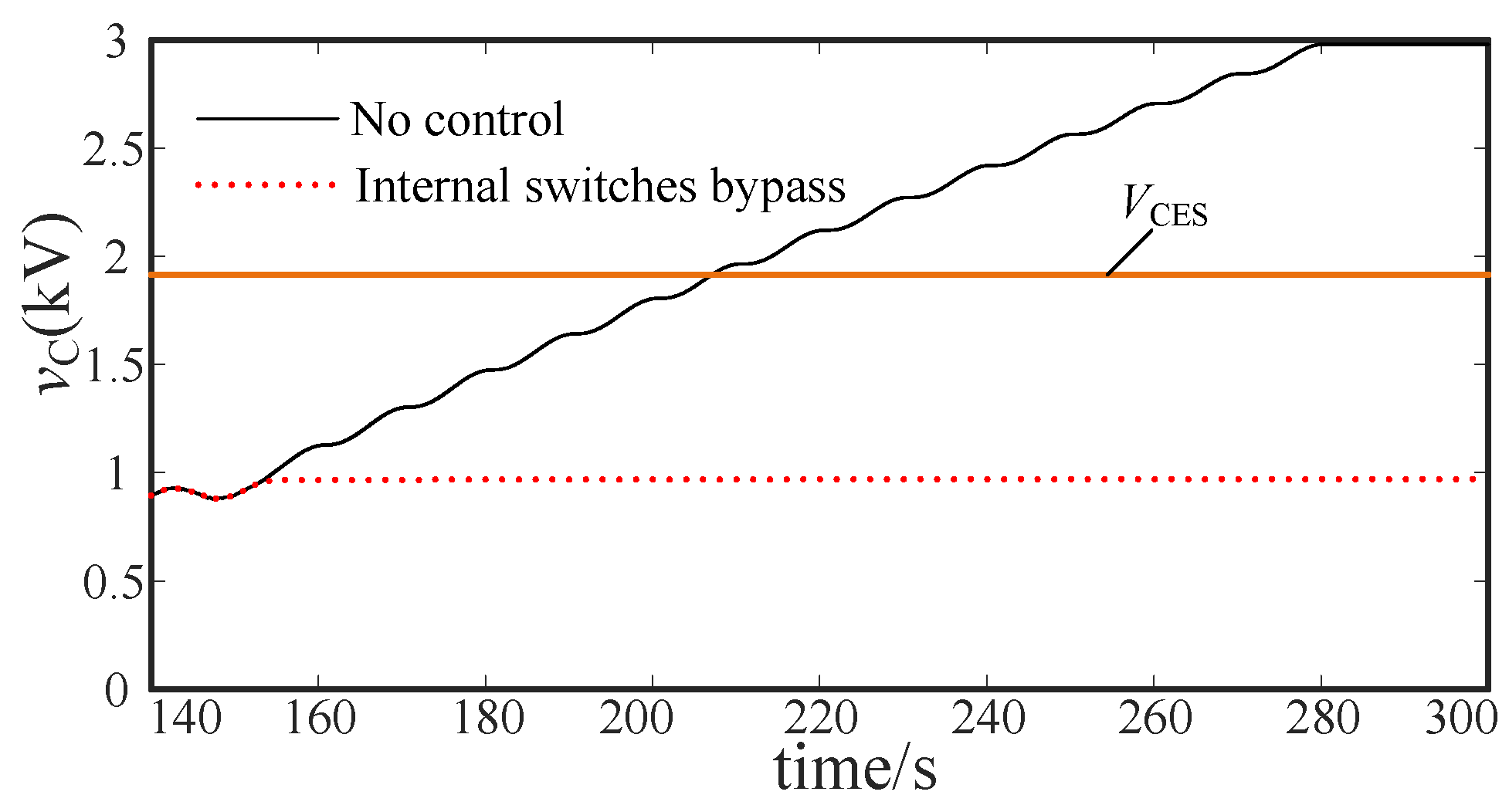
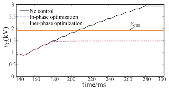
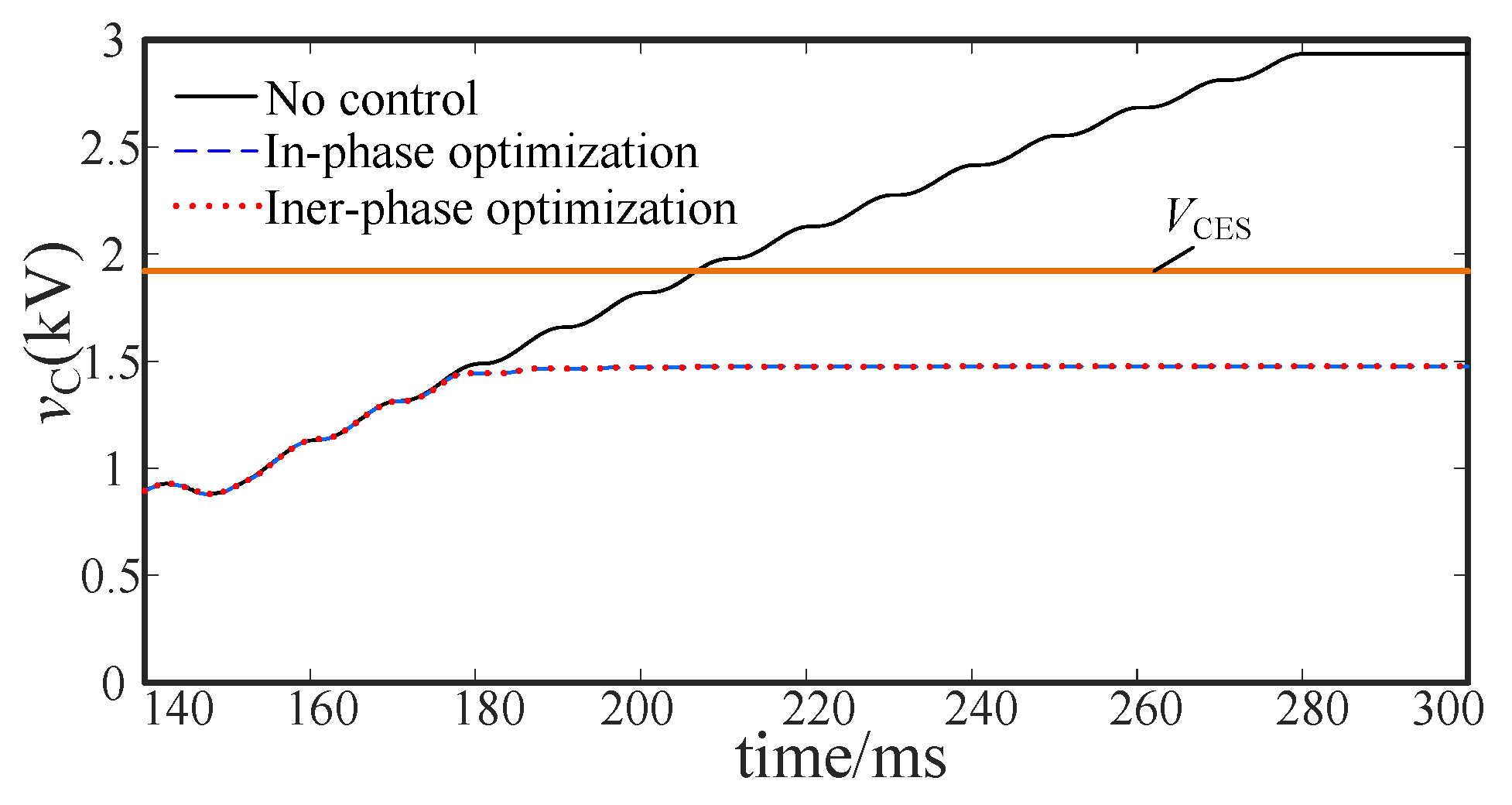
The safety of components in the power unit during a fault is also the focus of attention. Figure 32 shows the vC of controllable failure. Figure 33 shows the vC of uncontrollable failure. VCES is the saturation voltage of the IGBT. When the voltage across the IGBT is higher than VCES, IGBT may break down. The DC voltage of the power unit with fault ride-through will not continue to rise. It can be seen from the figure that the fault ride-through strategy can prevent IGBT overvoltage.
Figure 32.
vC of controllable failure.
Figure 33.
vC of uncontrollable failure.
5.5. Power Transmission Analysis
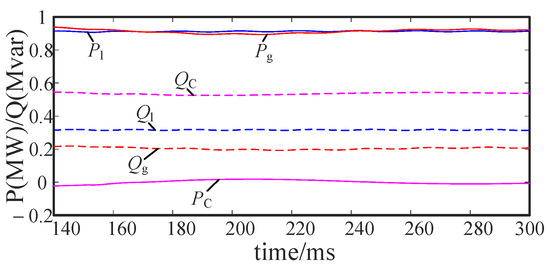
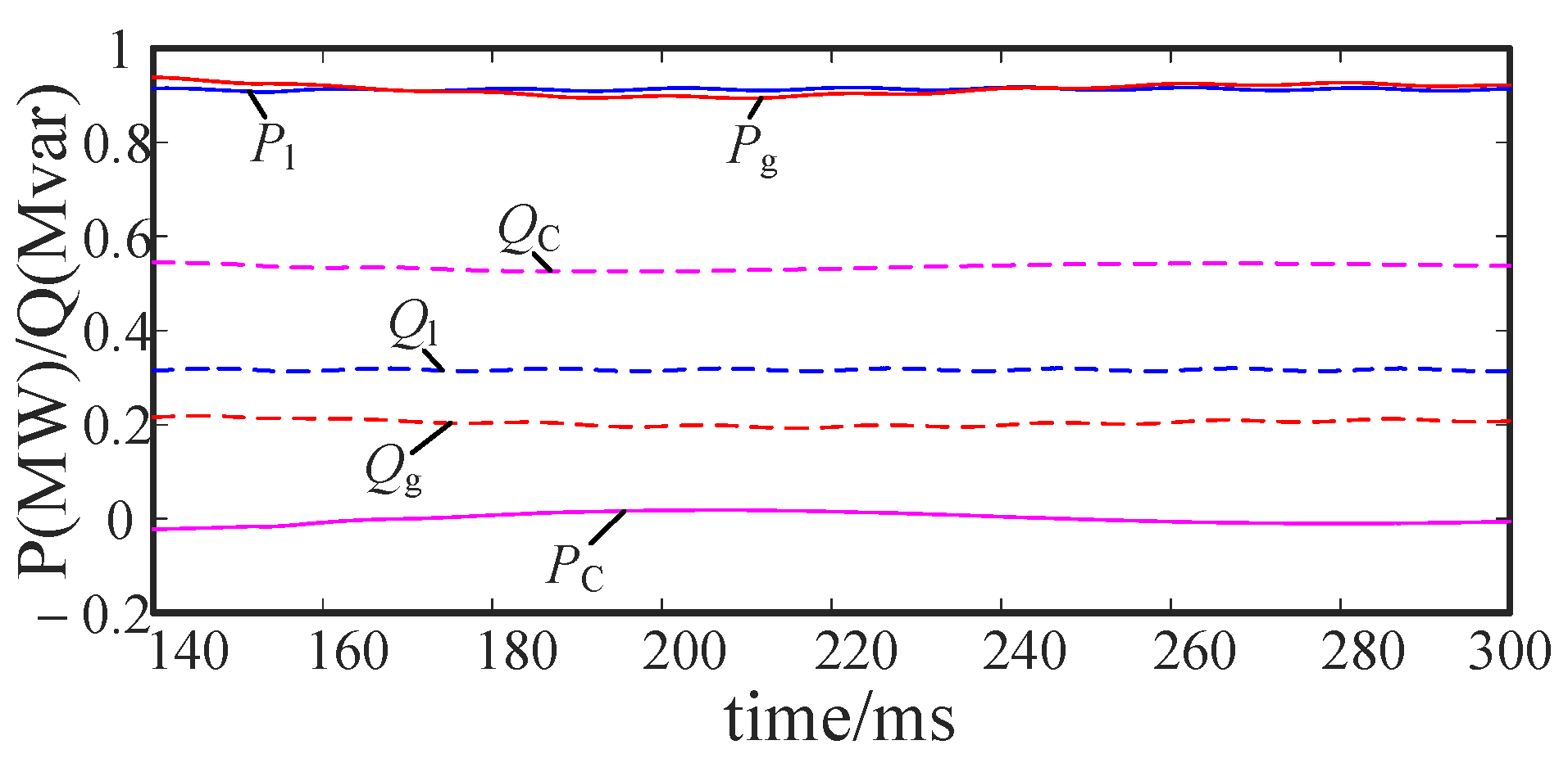
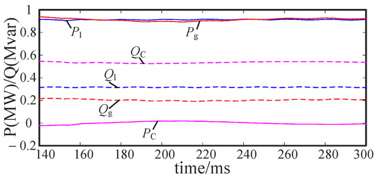
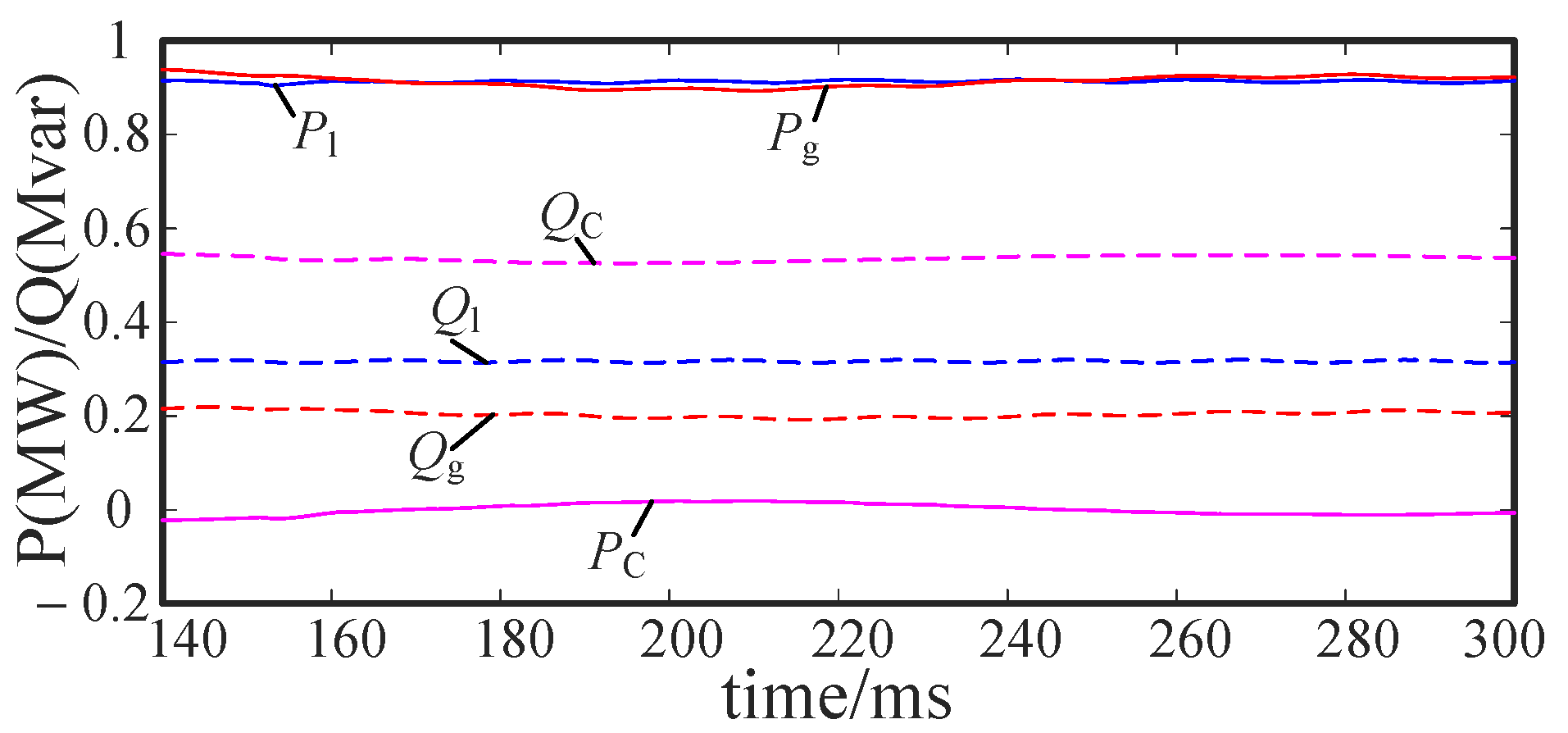
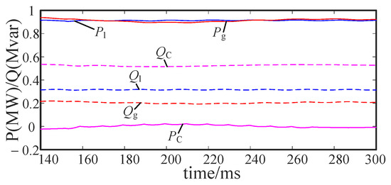
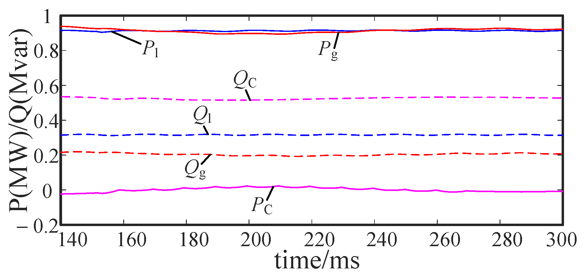
This section mainly focuses on the active and reactive power generated by the grid and CHB, the active and reactive power absorbed by the load. The efficiency of the device is mainly evaluated by active power transmission. Figure 34 shows the power transmission of the system under controllable fault. Figure 35 and Figure 36 are the power transmission of the system under uncontrollable faults. The power of the grid and the load are relatively stable. It can be seen that the fault ride-through strategy proposed in this paper has little effect on the power transmission of the device.
Figure 34.
Power transmission of controllable fault.
Figure 35.
Power transmission of intra-phase optimization under uncontrollable fault.
Figure 36.
Power transmission of inter-phase optimization under uncontrollable fault.
6. Conclusions
This paper studies the fault ride-through strategy for the H-bridge power unit failure of PQID and proposes a mechanical-switches based adaptive fault ride-through strategy. The conclusions are as follows:
- (1)
- Conventional mechanical switches cannot effectively bypass the failed power unit. Its slow closing speed will cause the output voltage quality to drop and the components to be damaged.
- (2)
- When a controllable fault occurs in the power unit, the internal switch bypass fault ride-through strategy is adopted. An intra-phase optimization or an inter-phase optimization fault ride-through strategy is adopted when an uncontrollable fault occurs in the power unit.
- (3)
- Compared with the no-fault ride-through strategy, the voltage stability and reliability are significantly improved, and the proposed fault ride-through strategy has economic advantages.
Author Contributions
Writing—original draft preparation, Y.S.; methodology, Y.X.; supervision, W.H., G.Z., M.H., F.Y. and W.Z. All authors have read and agreed to the published version of the manuscript.
Funding
This research was funded by State Grid Hubei Electric Power Co., Ltd. Project (52153220000J) and the Technology Innovation Project of Hubei Province (2019AAA015).
Institutional Review Board Statement
Not applicable.
Informed Consent Statement
Not applicable.
Data Availability Statement
Data sharing not applicable.
Conflicts of Interest
The authors declare no conflict of interest.
References
- Zhou, B.; Zou, J.; Chung, C.Y.; Wang, H.; Liu, N.; Voropai, N.; Xu, D. Multi-microgrid Energy Management Systems: Architecture, Communication, and Scheduling Strategies. J. Mod. Power Syst. Clean Energy 2021, 9, 463–476. [Google Scholar] [CrossRef] [Scilit]
- Tomin, N.; Zhukov, A.; Kurbatsky, V.; Sidorov, D.; Negnevitsky, M. Development of automatic intelligent system for on-line voltage security control of power systems. In Proceedings of the 2017 IEEE Manchester PowerTech, Manchester, UK, 18–22 June 2017; pp. 1–6. [Google Scholar]
- Hafezi, H.; D’Antona, G.; Dedè, A.; della Giustina, D.; Faranda, R.; Massa, G. Power Quality Conditioning in LV Distribution Networks: Results by Field Demonstration. IEEE Trans. Smart Grid 2017, 8, 418–427. [Google Scholar] [CrossRef] [Scilit]
- Zhang, Y.; Song, X.; Li, Y.; Zeng, Z.; Yong, C.; Sidorov, D.; Lv, X. Two-Stage Active and Reactive Power Coordinated Optimal Dispatch for Active Distribution Network Considering Load Flexibility. Energies 2020, 13, 5922. [Google Scholar] [CrossRef] [Scilit]
- Turner, R.; Elliott, N. A new UPS topology for multi-megawatt medium voltage power protection. In Proceedings of the 2018 IEEE International Conference on Industrial Electronics for Sustainable Energy Systems (IESES), Hamilton, New Zealand, 31 January–2 February 2018; pp. 245–249. [Google Scholar]
- Kouro, S.; Malinowski, M.; Gopakumar, K.; Pou, J.; Franquelo, L.G.; Wu, B.; Rodriguez, J.; Pérez, M.A.; Leon, J.I. Recent Advances and Industrial Applications of Multilevel Converters. IEEE Trans. Ind. Electron. 2010, 57, 2553–2580. [Google Scholar] [CrossRef] [Scilit]
- Xie, D.; Lin, C.; Deng, Q.; Ge, X.; Gou, B. Fast Diagnosis Scheme for Multiple Switch Faults in Cascaded H-Bridge Multilevel Converters. IEEE Trans. Transp. Electrif. 2021, 7, 1000–1015. [Google Scholar] [CrossRef] [Scilit]
- Lu, B.; Sharma, S.K. A Literature Review of IGBT Fault Diagnostic and Protection Methods for Power Inverters. IEEE Trans. Ind. Appl. 2009, 45, 1770–1777. [Google Scholar]
- Yang, S.; Bryant, A.; Mawby, P.; Xiang, D.; Ran, L.; Tavner, P. An Industry-Based Survey of Reliability in Power Electronic Converters. IEEE Trans. Ind. Appl. 2011, 47, 1441–1451. [Google Scholar] [CrossRef] [Scilit]
- Choi, U.; Blaabjerg, F.; Lee, K. Study and Handling Methods of Power IGBT Module Failures in Power Electronic Converter Systems. IEEE Trans. Power Electron. 2015, 30, 2517–2533. [Google Scholar] [CrossRef] [Scilit]
- Shao, S.; Yu, N.; Xu, X.; Bai, J.; Wu, X.; Zhang, J. Tunnel Magnetoresistance-Based Short-Circuit and Over-Current Protection for IGBT Module. IEEE Trans. Power Electron. 2020, 35, 10930–10944. [Google Scholar] [CrossRef] [Scilit]
- Neyshabouri, Y.; Iman-Eini, H. A New Fault-Tolerant Strategy for a Cascaded H-Bridge Based STATCOM. IEEE Trans. Ind. Electron. 2018, 65, 6436–6445. [Google Scholar] [CrossRef] [Scilit]
- Raj, N.; Anand, A.; Jagadanand, G.; George, S. Output voltage modeling of cascaded H-bridge multilevel inverters under open-transistor fault. In Proceedings of the 2016 IEEE Industrial Electronics and Applications Conference (IEACon), Kota Kinabalu, Malaysia, 20–22 November 2016; pp. 7–11. [Google Scholar]
- Zhao, T.; Zhang, X.; Wang, M.; Mao, W.; Li, F.; Wang, F.; Wang, X. Module Power Balance Control and Redundancy Design Analysis of Cascaded PV Solid-State Transformer Under Fault Conditions. IEEE J. Emerg. Sel. Top. Power Electron. 2021, 9, 677–688. [Google Scholar] [CrossRef] [Scilit]
- Song, W.; Huang, A.Q. Fault-Tolerant Design and Control Strategy for Cascaded H-Bridge Multilevel Converter-Based STATCOM. IEEE Trans. Ind. Electron. 2010, 57, 2700–2708. [Google Scholar] [CrossRef] [Scilit]
- Tian, J.; Mao, C.; Wang, D.; Nie, S.; Yang, Y. A Short-Time Transition and Cost Saving Redundancy Scheme for Medium-Voltage Three-Phase Cascaded H-Bridge Electronic Power Transformer. IEEE Trans. Power Electron. 2018, 33, 9242–9252. [Google Scholar] [CrossRef] [Scilit]
- Li, B.; Zhang, Y.; Yang, R.; Xu, R.; Xu, D.; Wang, W. Seamless Transition Control for Modular Multilevel Converters When Inserting a Cold-Reserve Redundant Submodule. IEEE Trans. Power Electron. 2015, 30, 4052–4057. [Google Scholar] [CrossRef] [Scilit]
- Tu, P.; Yang, S.; Wang, P. Reliability- and Cost-Based Redundancy Design for Modular Multilevel Converter. IEEE Trans. Ind. Electron. 2019, 66, 2333–2342. [Google Scholar] [CrossRef] [Scilit]
- Mirafzal, B. Survey of Fault-Tolerance Techniques for Three-Phase Voltage Source Inverters. IEEE Trans. Ind. Electron. 2014, 61, 5192–5202. [Google Scholar] [CrossRef] [Scilit]
- Dargahi, V.; Sadigh, A.K.; Corzine, K.A.; Enslin, J.H.; Rodriguez, J.; Blaabjerg, F. A New Control Technique for Improved Active-Neutral-Point-Clamped (I-ANPC) Multilevel Converters Using Logic-Equations Approach. IEEE Trans. Ind. Appl. 2020, 56, 488–497. [Google Scholar] [CrossRef] [Scilit]
- Yu, Y.; Konstantinou, G.; Hredzak, B.; Agelidis, V.G. Operation of Cascaded H-Bridge Multilevel Converters for Large-Scale Photovoltaic Power Plants Under Bridge Failures. IEEE Trans. Ind. Electron. 2015, 62, 7228–7236. [Google Scholar] [CrossRef] [Scilit]
- Ouni, S.; Narimani, M.; Cheng, Z.; Zargari, N.R. A New Postfault Control Method for CHB Inverter to Increase Maximum Output Voltage. IEEE Trans. Ind. Appl. 2020, 56, 5499–5510. [Google Scholar] [CrossRef] [Scilit]





Publisher’s Note: MDPI stays neutral with regard to jurisdictional claims in published maps and institutional affiliations. |
© 2021 by the authors. Licensee MDPI, Basel, Switzerland. This article is an open access article distributed under the terms and conditions of the Creative Commons Attribution (CC BY) license (https://creativecommons.org/licenses/by/4.0/).