1. Introduction
A significant increase of new heating and heating/cooling installations that is based on heat pumps and borehole heat exchangers (BHE) has been recently observed in many countries, including Switzerland [
1], Germany [
2], Sweden [
3], Canada [
4], and the United States [
5]. Borehole thermal energy storage (BTES) permits the extraction of heat from the ground for heating in winter and the extraction of cool (i.e., the input of heat) for air conditioning in summer [
6,
7]. A BTES is a type of geoenergetic system, which also includes energy systems that are based on geothermal waters. Geothermal energy utilisation is usually more problematic when it is connected with geothermal water rather than the ground.
The energy efficiency of a BHE mostly depends on the thermal conductivity of the underground rock mass. Other construction parameters also influence the energy efficiency. There are various types of BHEs, with the most typical being:
single U-tube;
multi U-tube;
BHEs can be vertically drilled. Alternatively, the BHE construction technology of Geothermal Radial Drilling (GRD) allows for directional (oblique) wells [
13]. GRD provides the possibility of using the ground under buildings for thermal energy storage by the placing of boreholes. The effectiveness for various BHEs of different constructions has been compared. For instance, the effective thermal conductivity and performance in closed-loop vertical ground heat exchangers have been compared [
14] and evaluated with TRTs [
15], while the performances of the U-tube, concentric tube, and standing column well ground heat exchangers have been compared while using simulation [
16]. Additionally, the thermal performances have been assessed for various types of underground heat exchangers [
17] and for borehole heat exchangers specifically using TRTs [
18]. The latter study included an analysis and comparison of interpretation methods.
BTES efficiencies in the literature consider such factors as borehole array geometry [
19], heat transfer from the surroundings [
20,
21], grout parameters [
22], freezing of underground water [
23], and underground water flow. Studies that account for underground water flow include examinations of the influence of groundwater on: pile geothermal heat exchanger with cast-in spiral coils [
24], closed-loop ground-source heat pump systems [
25], the heat transfer in ground heat exchangers [
26], the optimization of large-scale ground-coupled heat pump systems [
27] and vertical closed-loop geothermal systems [
28], the simulation of borehole heat exchangers [
29], and the performance of geothermal heat exchangers [
30]. Reference [
31] describes many factors concerning coaxial BHEs.
The thermal response test (TRT) is an accurate and conventional method for the determination of the thermal properties of different cases of borehole heat exchangers [
32]. A TRT is typically performed in large installations (over 100 kW) for an exploration BHE. According to [
33], the TRT is an economic test for a lower capacity limit of about 30 kW. When the thermal parameters of the analyzed borehole heat exchanger are known, it is possible to establish the number of boreholes that are needed to satisfy heating and/or cooling demands.
Much work is being carried out to improve TRTs. For instance, a distributed TRT approach is described in [
34]. The measuring process during a disturbed TRT (i.e., one with thermal sensors inside the BHE) affects the results. Sensors inside a BHE cause local turbulences and pressure losses, rendering the measuring unsettled/distorted. New methods for the interpretation of TRT results using statistics are described in [
35,
36]. The factors that are considered in a TRT are described in [
37], for example, outdoor air temperature. Error analysis for a TRT is described in [
38].
A TRT can be performed using various methods, e.g., the method that is described by Eskilson [
39] and the computer code Earth Energy Designer (EED), which was developed following that method. Additionally, the extent of an underground thermal energy storage, i.e., the number and distribution of borehole heat exchangers, can be determined with numerical modeling, e.g., [
40] or with commercial simulators [
41].
Thermal response tests and mathematical modeling can also be used for determining the energy efficiency for thermal purposes of oil and gas wells, which have the potential for conversion to borehole heat exchangers [
42]. This application has attracted increasing interest in recent years, especially for deep borehole heat exchangers, and it has correspondingly been subject to analysis by energy specialists in academe and industry.
BHE modeling also needs to account for thermal stresses. Doing so is essential for large installations that are connected with thermal waters and heat recovery from enhanced geothermal systems [
43,
44] and large BHE fields. The methods of thermal stress calculation that are used in the oil and gas industry can be applied for geothermal wells (and BHEs) [
13].
In this article, we propose and verify a new method of establishing effective thermal conductivity of BHEs and assessing the usefulness of this method for utilization with thermal response tests. Existing methods provide the BHE thermal resistivity (
Rb) as a function of the time of the TRT, whereas it should be constant in time. The method that is proposed here rectifies this shortcoming. That is, it is often possible to observe a change in
Rb with time during a TRT [
45]. Sometimes the change is an increase and at other times a decrease. Since the formula includes the effective thermal conductivity of the BHE (
λeff), the value of
λeff can be found, which yields a constant function
Rb with time.
The novelty of this article lies in it presenting a new enhancement to a methodology. The methodology is described in the paper and verified while using the analyses of two TRTs. The main contribution and scientific significance is that it assists efforts to interpret TRTs better, so as to avoid tests providing erroneous or problematic results. Problematic TRTs occur quite often in practice.
The proposed new approach is based on the equation for the thermal resistivity of a BHE Rb in the function of the thermal conductivity of a rock mass λ or effective thermal conductivity λeff, as determined on the basis of a TRT. The new methodology is based on the assumption that Rb does not depend on the duration of the TRT, an assumption that corresponds to reality.
The basic assumption of the new approach can be expressed by the formula Rb = f(t) = constant. The equation Rb = f(t) can be developed into the dependence of Rb = kt + b. According to the model assumption kt + b = constant, the equation is spilled if and only if k = 0. The determination of thermal conductivity λx and BHE thermal resistivity Rb is reduced in this methodology to determining such a value of λx, to obtain k = 0. Subsequently, we get Rb = b.
2. Thermal Response Test Mathematical Background
According to the well-established Kelvin infinite line source theory thermal response test was developed [
46]. The TRT methodology is based on the partial differential equation form of the Fourier thermal conductivity equation, which describes the dynamic dependence of temperature
T on the distance from heat exchanger
r and duration of the test
t, i.e., determines
. The equation has the following form:
One method of solving such a partial differential equation involves substitution. This transforms the partial differential Equation (1) to an ordinary differential equation. Perina [
47] has used this approach to describe the Theis equation in hydrogeology, which gives the pressure distribution
p =
p(
r,
t). To use this approach, we let
and
Subsequently, we can show that
and Equation (1) assumes the following form:
Returning to the Substitution (4), we finally obtain
In view of the substitution in Equation (4), and by substituting the integral in (6) with an approximate expression, we obtain
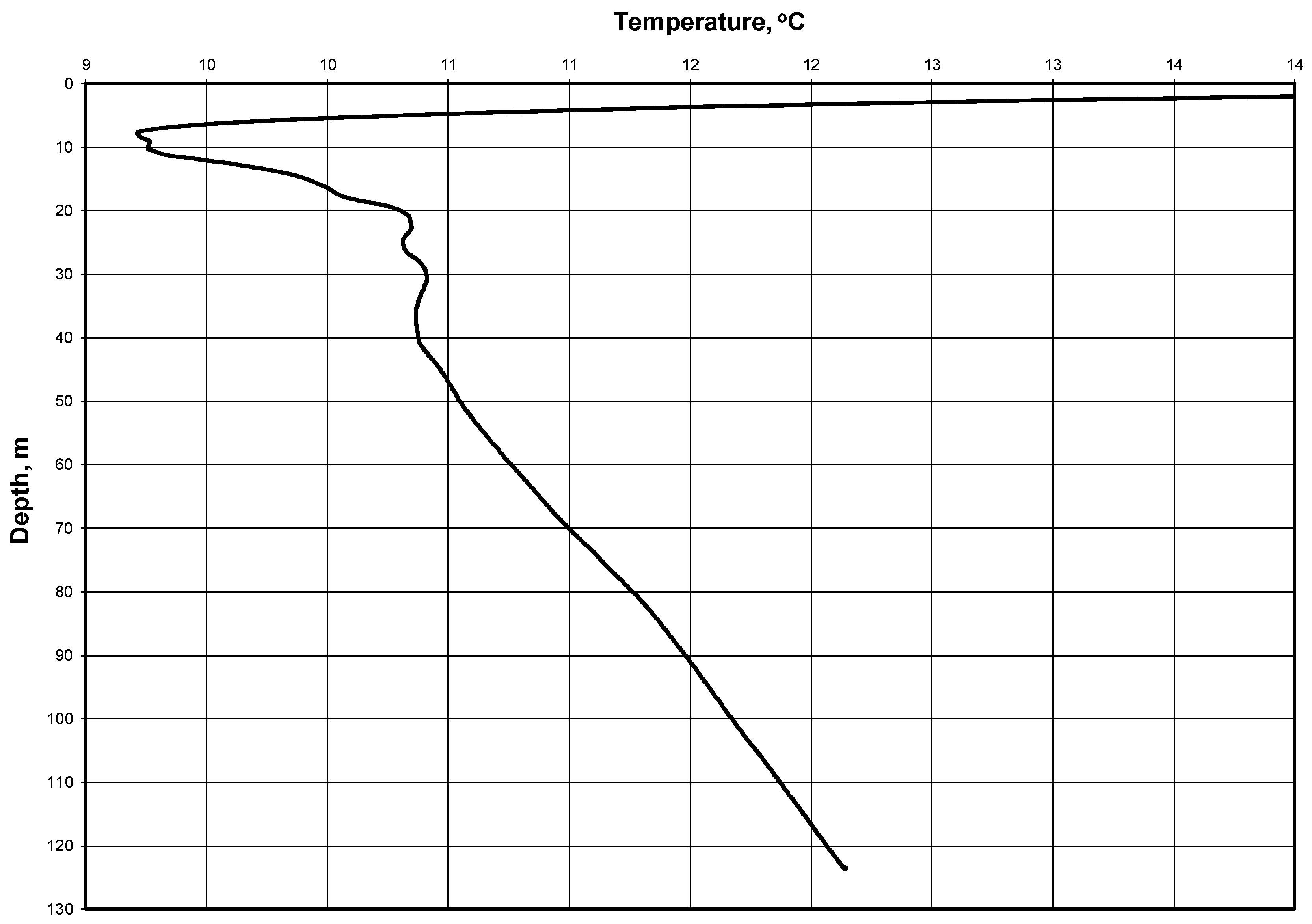
Regarding initial and boundary conditions, it is noted that the solution obtained is not numerical. Rather, it is analytical and the idea of the mathematical model of the TRT is based on an infinite linear heat source. Accordingly, we do not solve the differential equation in a finite region. The (linear) source has a length that corresponds to the borehole depth. The time of the TRT is limited (max. 100 h). The initial temperature corresponds to the natural temperature distribution, as seen in
Figure 1, but it is normally approximated with one initial temperature:
To.
3. Two Thermal Response Tests
The Thermal Response Test (TRT), which is sometimes called the Geothermal Response Test (GRT), is a suitable method in determining the effective thermal conductivity of the ground and the borehole thermal resistance (or the thermal conductivity of the borehole fill). A temperature curve is obtained, which can be evaluated by several methods. The resulting thermal conductivity is based on the total heat transport in the ground. Other effects, like convective heat transport (in permeable layers with groundwater), and further disturbances are automatically included, so it may be more correct to speak of an “effective” thermal conductivity
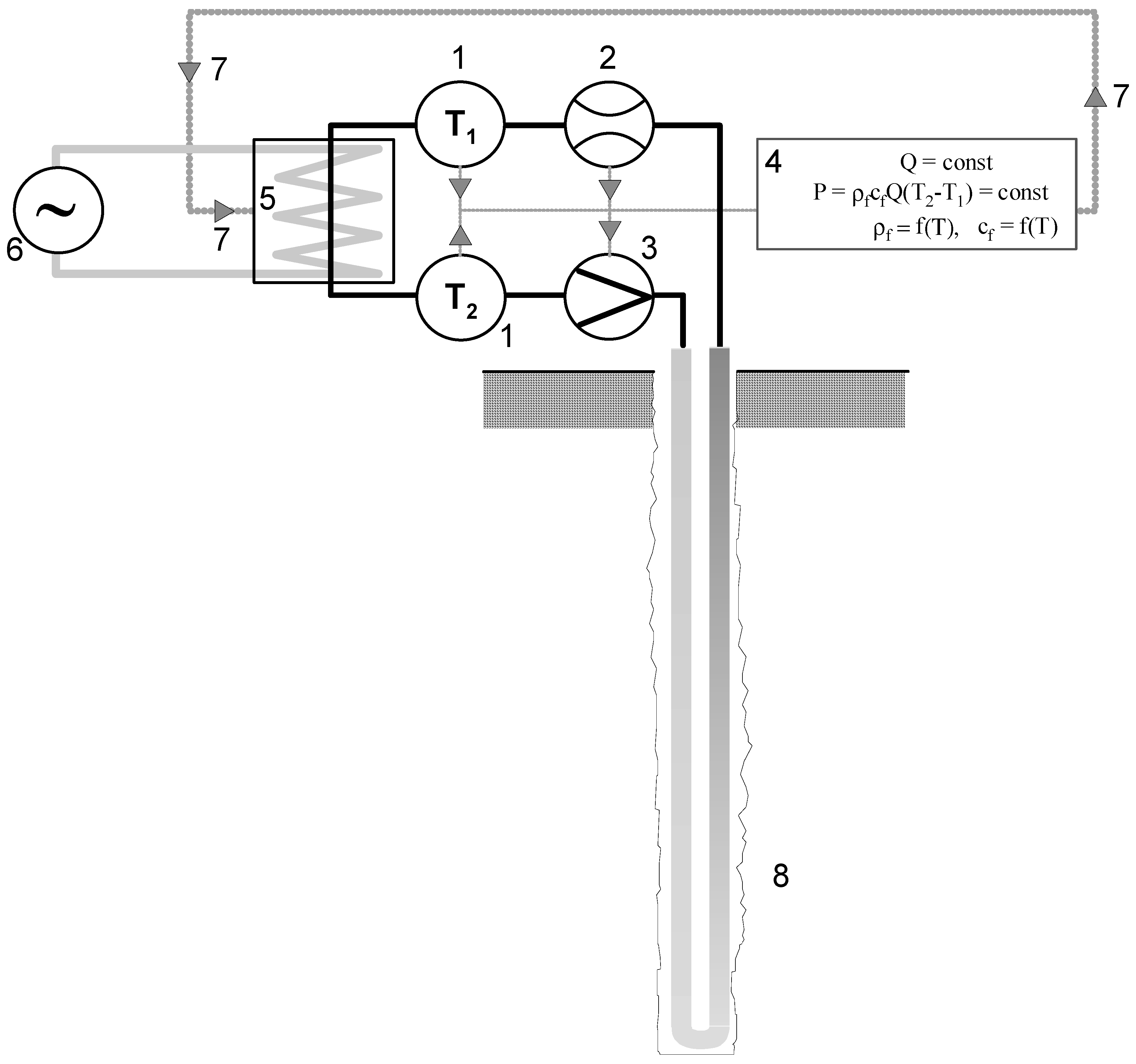
λeff. The test equipment can be made in such a way that it can be easily transported to the site, e.g., on a light trailer (
Figure 2) [
48]. In short, a TRT relies on forcing the closed circulation of a heat carrier that is heated with a constant heating power. The temperature change with time is analyzed.
The TRT involves introducing and collecting energy from a borehole heat exchanger (
Figure 2). During the tests, the heat carrier is most frequently heated at a constant heating power
P, which is measured, and the temperatures
T1 and
T2 are then recorded. The heating power is maintained by switching the heaters on and off. The automation system takes into account the variability with the temperature of the heat carrier density
ρ and the specific heat at constant pressure
cp.
This section describes two actual thermal response tests. The Laboratory of Geoenergetics, Faculty of Drilling, Oil, and Gas, AGH University of Science and Technology in Krakow, Poland performed the tests and analyses [
49,
50]. The tests were carried out to illustrate and compare the results from the old and new methods of TRT interpretation.
For the sake of interpretation, it is noted that the TRT was performed for a borehole heat exchanger, the geological profile of which is presented in
Table 1. The first test was performed in Żarów (Dolnośląskie Region, Poland) in 2011. The average heating power during the test was
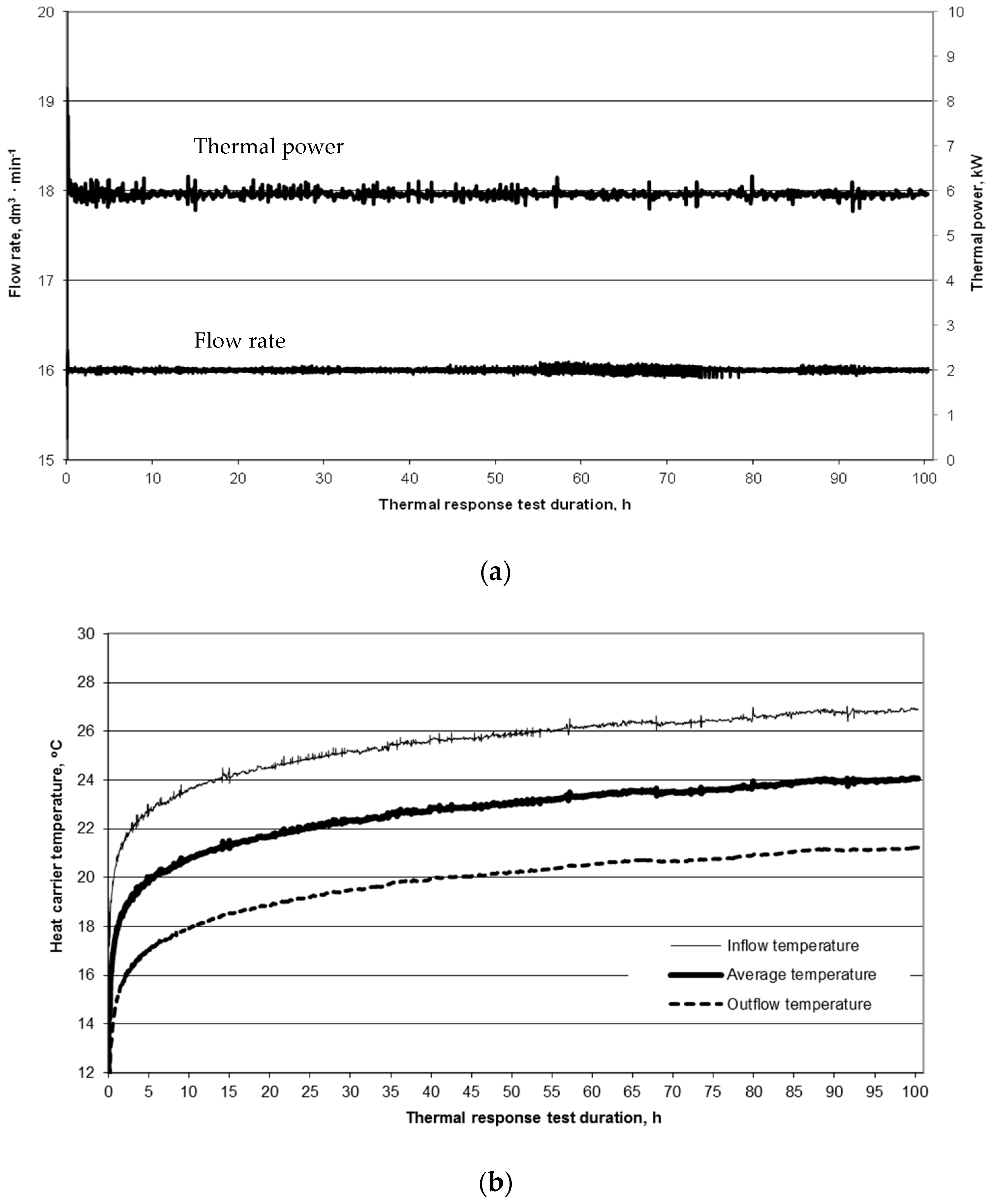
P = 5920 W and the volumetric flow rate of the carrier was 16 dm
3∙min
−1 (
Figure 3a). The control of the volume value of the heat carrier volumetric flow rate was carried out with a rotary (windmill) flowmeter with an accuracy of 0.25 dm
3 per one impulse. The flow measurements have the task of only visual control of the correctness of the TRT execution, where the relationship Q = const should be satisfied. Similarly, for the value of heating power P, which is calculated on the basis of temperature measurements from the dependence
P =
QρcΔ
T, the visual relationship (
Figure 3a) should be observed during the entire test to ensure
P = const.
The borehole heat exchanger is
H = 120 m deep, so the heat exchange per unit of depth is
q = 49.34 W·m
−1. In the linear heat source model, the unit heating power is assumed to be uniform. A constant temperature is also assumed in the model for the heat carrier and the ground.
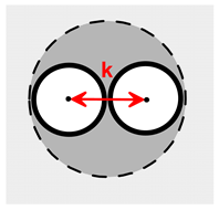
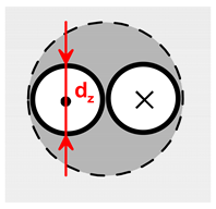
Table 2 presents the design of the borehole heat exchanger.
A second TRT was performed in the BHE at the Laboratory of Geoenergetics in the university, where the lithological profile is as described in
Table 3.
The values of
Do,
dz,
Hb,
b, and
H (in Equation (8)) in
Table 2 were provided by a company making a BHE without any data on measurement accuracy. The value of
λg comes from the literature [
51].
Figure 3b presents the curves illustrating the data during the TRT test, where the dependence on the duration of the test is observed. The average thermal conductivity that is assumed for rocks of 2.15 W·m
−1·K
−1 is based on data in the literature [
51], as is the average volumetric specific heat of rocks in the profile of 2.17 MJ·m
−3·K
−1 [
52,
53]. A 35% propylene glycol solution is used as the heat carrier. At 20 °C, the specific heat of the carrier is 3810 J∙kg
−1·K
−1 and its density is 1028 kg∙m
−³.
The average temperature of the rock mass is determined on the basis of the heat carrier circulation, without heating (i.e., before the TRT heating phase begins). The return flow temperature is 11.1 °C and the mean measured air temperature is 16.1 °C. The mean natural temperature in the borehole can also be determined on the basis of temperature logging [
54]. The mean temperature of the rock mass, based on the temperature profile (
Figure 1), is 11.00 °C. The NIMO-T (Non-wired Immersible Measuring Object for Temperature) was used for temperature profiling in BHE. The relative error of the temperature measurement was 0.0015 °C and the absolute error was 0.1 °C [
54].
The thermal diffusivity
α = 0.97·10
−6 m²·s
−1 is calculated using data from the literature [
51] and Equation (3).
The mean temperature of the heat carrier flowing into the BHE during the test is 25.48 °C and the mean return flow temperature is 19.82 °C. Thus, the mean temperature difference is 5.67 °C and the mean temperature of the heat carrier is 22.65 °C.
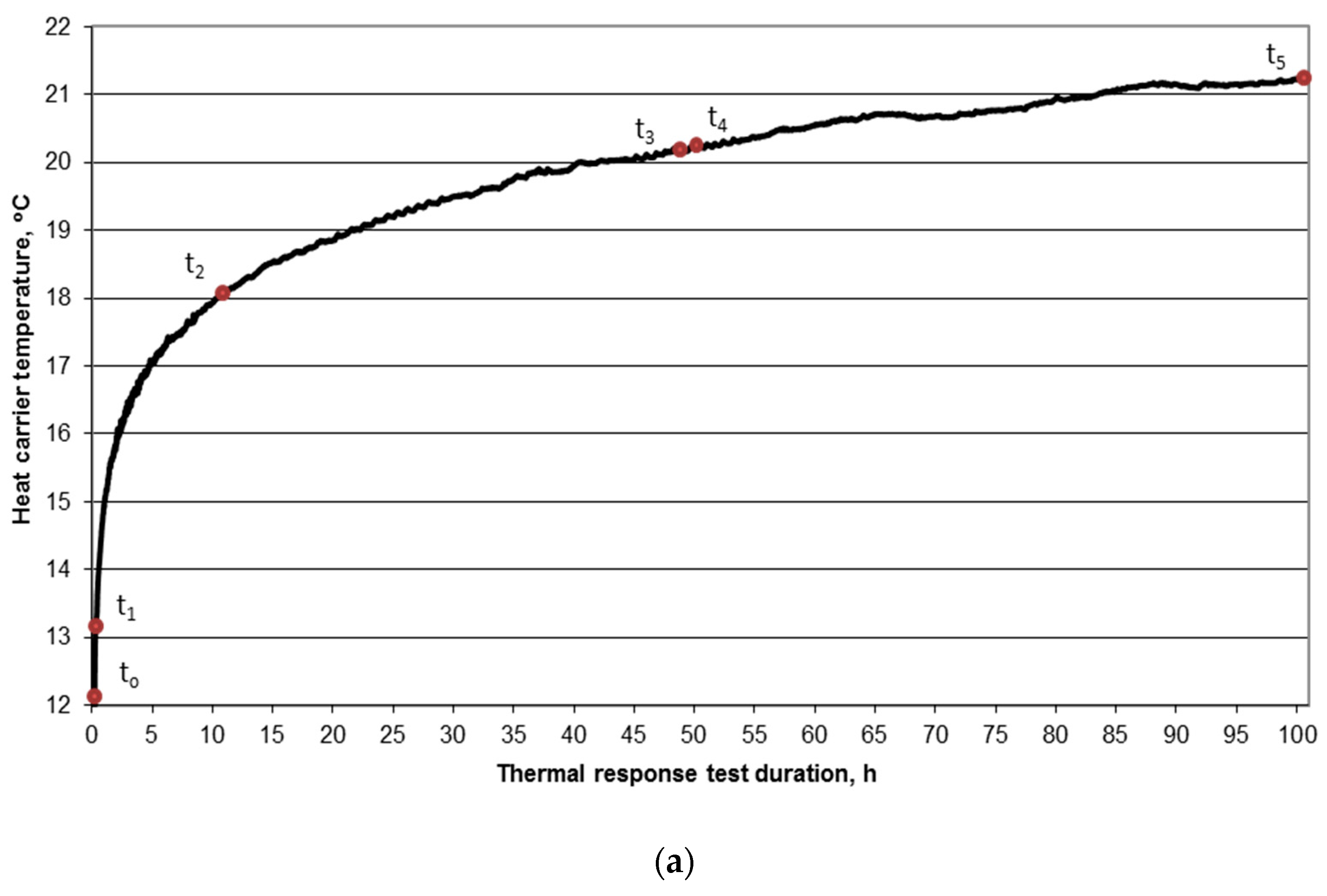
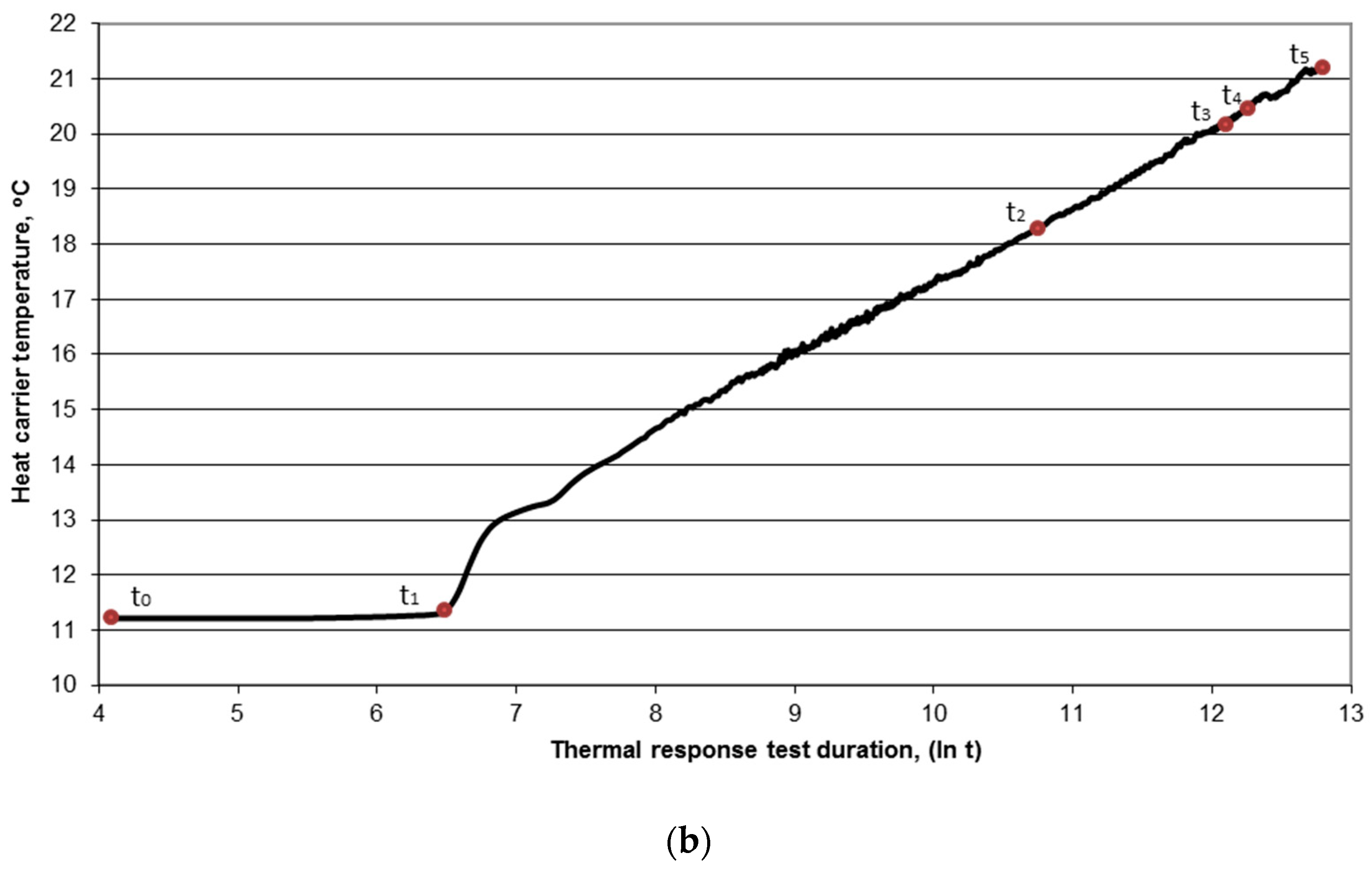
Figure 4 shows the characteristic times that are used for the interpretation of TRT results. There, the points are denoted, as follows:
t0 the beginning of heating phase of the test (heaters on),
t1 the slope point of the curve (time of the first complete circulation loop of the heat carrier),
t2 the time corresponding to t =
,
t3 the time corresponding to t =
,
t4 the half-time of the heating phase of the test, and
t5 the end of the heating phase of the test (heaters off).
The following values were obtained during the test: t0 = 0, t1 = 480 s (0.13 h), t2 = 46348 s (12.87 h), t3 = 185391 s (51.50 h), t4 = 180660 s (50.18 h), and t5 = 361320 s (100.37 h). Linear regression analysis is used for determining coefficients of line slope in the semi-logarithmic system (log t) for the following time intervals:
from t0 to t5
from t1 to t5
from t2 to t5
from t0 to t2
from t0 to t3
from t2 to t3
from t1 to t4
from t3 to t5.
The values of the slope coefficient
k and the effective thermal conductivity
λeff are calculated on the basis of Equation (7), as follows:
Table 4 lists the results, including the average values of the BHE thermal resistivity
Rb and values for various data intervals. The value of
Rb is calculated, as follows:
Here, values for
λ can be taken from the literature (
λ = 2.15 W∙m
−1∙K
−1 from
Table 1) or calculated with Equation (7).
In
Table 5, the TRT results are shown for a BHE belonging to the Laboratory of Geoenergetics, Faculty of Drilling, Oil, and Gas AGH–University of Science and Technology for a heat carrier volumetric flow rate of 12 dm
3·min
−1 and heating power
P = 4000 W. The lithological profile of the borehole was described earlier (
Table 5), as was the design of the borehole heat exchanger (
Table 2).
The correlation coefficient for two TRTs was calculated. It concerned the temperatures dependence of the heat carrier and the duration of TRT. In both cases, the correlation coefficient had a higher value than 0.925.
4. A New Way of Determining Parameters from TRTs
Although the test (
Figure 3b) was carried out almost ideally, there are discrepancies in the BHE thermal conductivity and thermal resistivity values. These discrepancies stem from the different ranges of data that are assumed for the analyses. Therefore, a new way of determining the parameters
λeff and
Rb is proposed.
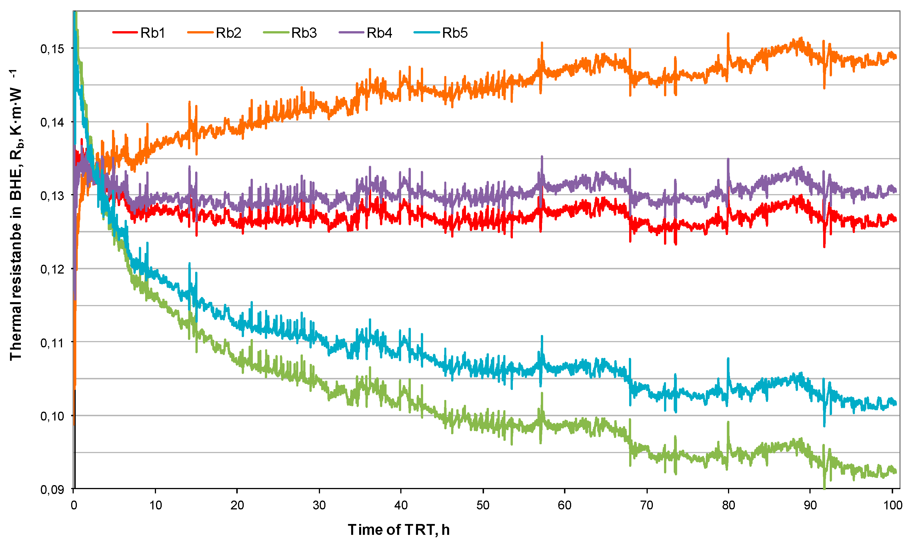
Figure 5 presents a graph showing the dependence of BHE thermal resistivity on test duration. The curves for
Rb1 and
Rb4 are more ‘linear’ in
Figure 5 than the curves for
Rb2,
Rb3, and
Rb5. Both of the curves only differ in the value of
λ from Equation (8).
The proposed approach involves determining a value of λ for which linear regression that is based on Rb = f(t) assumes the form of a function Rb = kt + b with a slope coefficient k of zero. The task of determining λ and Rb values reduces to finding a λ value, for which k = 0, after which we have Rb = b. For the TRT that was performed in Żarów, we determined the following pairs of values meeting this requirement: λeff = 2.77 W·m−1·K−1 and Rb = 0.129 m·K·W−1. This contrasts with the values obtained with the traditional method of λ = 2.81 W·m−1·K−1 and Rb = 0.130 m·K·W−1.
For the TRT performed at the BHE of the Laboratory of Geoenergetics, we find λ = 1.98 W·m−1·K−1 and Rb = 0.134 m·K·W−1 (whereas with the traditional method λ = 1.97 W·m−1·K−1 and Rb = 0.128 m·K·W−1).
Figure 5 shows the relation of
Rb with time from the TRT for the test in Żarów. The curves of
Rb = f(
t) only vary due to the value of
λ in Equation (9). The waveforms represent the following:
Rb1–graph of BHE thermal resistance vs. time for the conductivity λeff calculated for data from a time equal 5r02∙α−1 to the end of the heating phase of TRT (λeff = 2.70 W∙m−1∙K−1)
Rb2–graph of BHE thermal resistance vs. time for the conductivity λ = 125% λeff (λ = 3.37 W∙m−1∙K−1);
Rb3–graph of BHE thermal resistance vs. time for the conductivity λ = 75% λeff (λ = 2.03 W∙m−1∙K−1);
Rb4–graph of BHE thermal resistance vs. time for the conductivity when linear regression yields a constant function (for which k = 0 in the function Rb = kt + b), according to the new method described above (λ = 2.80 W∙m−1∙K−1); and,
Rb5–graph of BHE thermal resistance vs. time for the conductivity based on data in the literature, as in
Table 1 (
λ = 2.15 W∙m
−1∙K
−1).
The values of
Rb and
λeff for various time intervals calculated based on the new methodology are listed in the
Table 6 for the TRT at Żarów and in
Table 7 for the TRT at the Laboratory of Geoenergetics.
5. Results and Discussion
The thermal response test is the most favored way of determining the basic BHE parameters. The effective thermal conductivity λeff is the most important value for characterizing a BHE, and it is used for determining its energy efficiency. The effective thermal conductivity is mainly dependent on the thermal conductivity of rocks λ, especially when the BHE has been correctly performed. In reality, λeff is also dependent on the heat transfer resistivity between the heating agent circulating in the BHE and the rock mass. This heat transfer resistivity accounts for:
transfer of heat from the heating agent to the material (most frequently U-tubes), which depends on, among other factors, its viscosity;
heat conduction through the material (U-tube), which is affected by its thermal conductivity, e.g., for the case of a polyethylene tube λ = 0.42 W·m−1·K−1;
heat flow between the material of U-tube and the BHE filling/sealing material, where discontinuities may occur; and,
Heat flow between the BHE filling/sealing material and rock mass, where some discontinuities may be encountered.
An analysis of the experimental and analytical results reveals that, despite a correctly performed TRT, the values of
λeff are not constant with the time of test. This is caused by the assumed duration of the test. Such differences with respect to the value that was obtained for the full time of the test (100 h) may as great as 16.50%, relative to the traditional method (
Table 5), and 9.69% for the new method (
Table 7). The greatest percentage difference between the values of
λeff and
Rb are underlined in bold in
Table 4,
Table 5,
Table 6 and
Table 7. The relative change of
Rb or
λeff with respect to the full measurement range is calculated in %, relative to the values in the first time interval (
t0 to
t5). Accordingly, the percentage difference for this interval (i.e., the full range of data,
t0 to
t5) is always zero.
The new method is observed to be more accurate and stable in time for calculating the effective thermal conductivity
λeff in BHEs. However, when analyzing the BHE thermal resistivity
Rb, larger discrepancies can be observed for relative deviations from the basic value (for the full test duration). A maximum deviation of 1.80% for the traditional method (
Table 5) and 9.70% for the new method is observed (
Table 7). The greatest differences are observed for the TRT performed at the Laboratory of Geoenergetics, Faculty of Drilling, Oil, and Gas, AGH University of Science and Technology. For TRTs performed in Żarów, the corresponding deviations are much smaller. Therefore, more analyses of TRT data are needed while using the new methodology to assess these discrepancies, and that is the topic of ongoing research by the authors.
Many more analyses of TRT results are needed, along with the corresponding statistical analyses, to choose a better method for the interpretation of TRT results. In practice, there is no ideal TRT. The functional variation of temperature with time has many distortions. Simultaneously with improving TRT interpretations, the TRT measuring procedure also needs improvement. The inflow of material at the outside temperature should be reduced/eliminated, and a reliable automatic system is needed for maintaining a constant heating power when the variable voltages are present in the electrical network. Both of these requirements are being addressed at the Laboratory of Geoenergetics.
The accuracy of the calculation of the effective thermal conductivity coefficient and the thermal resistance has not been extensively examined in this article. That is because the target of this article is to describe the new methodology. Research by the present authors is ongoing to assess the precision of the results that were obtained with the new method, and it is expected to be reported soon.
6. Conclusions
The thermal response test is the most accurate way of determining parameter values of borehole heat exchangers. The effective thermal conductivity λeff and thermal resistivity of borehole Rb can be used in the design of an appropriate number of borehole exchangers for a given heating power demand and for a given time duration.
However, when interpreting the thermal response test, there are sometimes problems with the resulting values. That is, the values of thermal conductivity λeff and thermal resistivity Rb can differ depending on the assumed range of data, especially the time data. Various values of basic parameters are seen to be obtained, even for correctly performed tests, when analyzing various TRT time intervals.
The proposed method of determining basic TRT parameters is based on the BHE thermal resistivity Rb equation. This dependence (Equation (9)) is also observed to be a function of effective thermal conductivity λeff of the borehole heat exchanger. It is suggested that, a pair of the test results, i.e., effective thermal conductivity λeff and BHE thermal resistivity Rb, can predict the dependence of resistivity as a function of time, such that the slope coefficient of the regression line that is based on this approach is zero.
It is concluded from the analyses that the proposed new method of determining the values of the basic parameters of a BHE is more accurate and independent of thermal response test duration. The differences that were obtained for various TRT times with the proposed method for λeff are lower than with the traditional method. However, larger differences are obtained for Rb. Further work to assess the usefulness of this method in the interpretation of TRT data appears to be merited.




 ,
,