


Abstract
A new clinical device, the subtalar joint axis locator, was created to track the three-dimensional location of the subtalar joint axis during weightbearing movements of the foot. The assumption was that if the anterior exit point of the subtalar joint axis is stationary relative to the dorsal aspect of the talar neck, then, by performing radiographs of the feet with the subtalar joint axis locator in place on the foot, the ability of the locator to track rotations and translations of the talar neck and thus the subtalar joint axis in space could be approximated. In this preliminary study of two adults, the subtalar joint axis locator accurately tracked the talar neck position during weightbearing rotational motions of the subtalar joint. The device was also used in a series of subjects to determine its dynamic capabilities. It is possible, then, that the subtalar joint axis locator can reliably track the spatial location of the subtalar joint axis during weightbearing movements of the foot.
Kirby[1–4] suggested that the spatial location of the subtalar joint axis may have a profound effect on foot function and that it affects the moments produced around the subtalar joint and, ultimately, all of the joints of the foot. Fuller[5] advanced this work further by demonstrating how the interrelationship between the center of pressure on the plantar foot and the spatial location of the subtalar joint axis may lead to abnormal stresses in the tissues and how this information may be used to predict pathology. This work forms the basis of a new paradigm of podiatric medical biomechanics: the subtalar joint axis location and rotational equilibrium theory of foot function.[6]
It would seem reasonable, then, that knowledge of the spatial location of the subtalar joint axis during weightbearing activities would be clinically useful, offering invaluable insight into the normal and abnormal function of the foot. Indeed, Kirby (quoted by Menz[7]) stated that “accurate determination of the spatial location of the STJ axis in relationship to the plantar foot would help greatly in increasing our knowledge of foot and lower extremity biomechanics.” Recent research supports this contention that the subtalar joint spatial location may affect the biomechanics of the foot and lower extremity significantly enough to influence the anatomical location of mechanically related symptoms in the foot and lower extremity.[8]
Although researchers have tried for years, using simple and sophisticated methods, to determine the spatial location of the subtalar joint axis, the literature reveals no clinically viable method that would allow tracking of this location in three dimensions during weightbearing function.[8–18] With this in mind, we set out to develop an instrument that would allow this type of tracking: the subtalar joint axis locator (SJAL).
Materials and Methods
The SJAL is a device that consists of a clamping system that locks onto the calcaneus and two pointers that are attached to each other by means of a frame. The pointers may be aligned relative to the clamping system, in three dimensions, to correspond to the anterior exit point of the subtalar joint axis on the anterior talus and to the posterior exit point of the subtalar joint axis on the posterior calcaneus (Fig. 1). Two subjects participated in this preliminary study: one man (age, 31 years; height, 6 feet 2 inches; and weight, 186 pounds) and one woman (age, 34 years; height, 5 feet 4 inches; and weight, 119 pounds). The methods used during this research conformed to ethical principles, and both subjects gave written informed consent. Ethical approval was granted by the research and ethics committee of the Plymouth School of Podiatry.
Identifying the Exit Points of the Subtalar Joint Axis
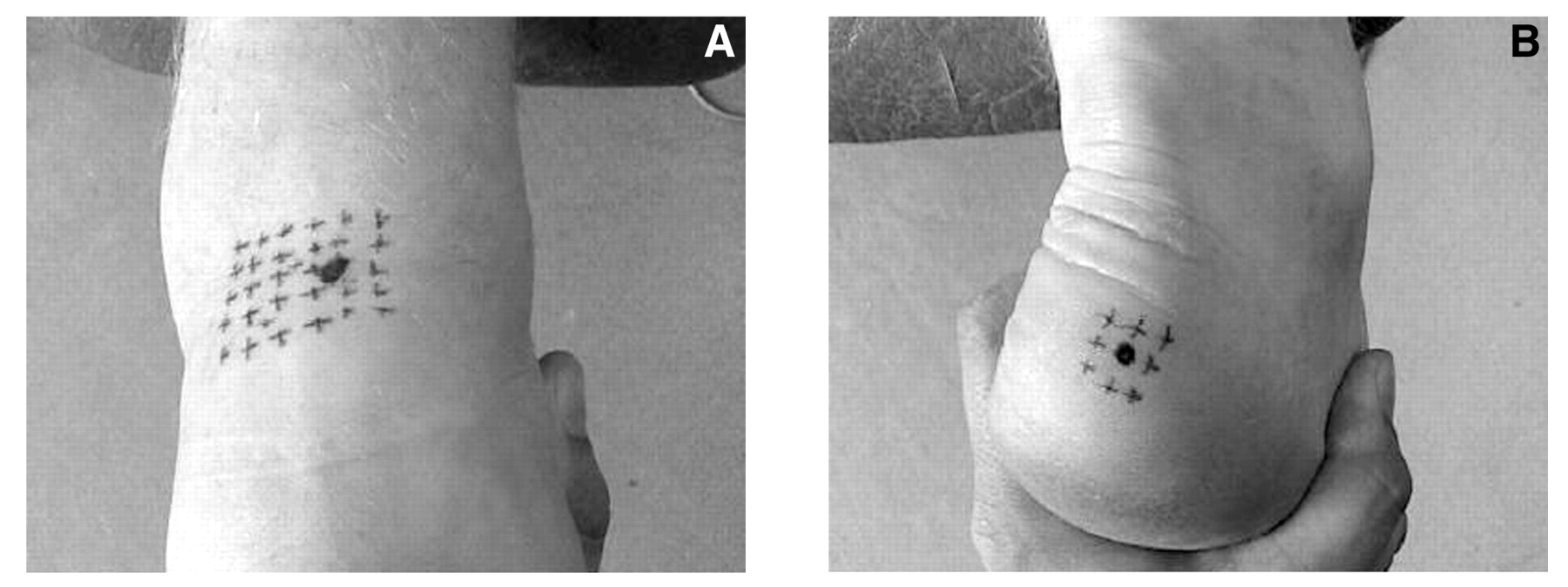
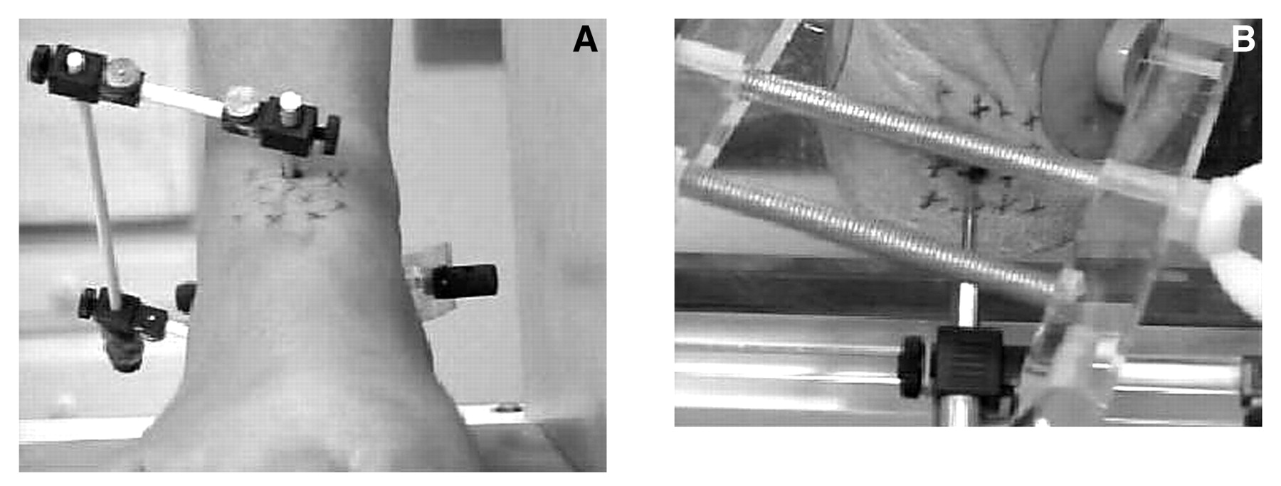
The anterior and posterior exit points of the subtalar joint axis were identified using the techniques described by Morris and Jones[16]: with the subject supine, a grid of dots was marked on the skin overlying the anterosuperior aspect of the talar head and neck. While the clinician viewed the foot from the front, the subtalar joint was put through its range of motion. By observing these dots on the skin during subtalar motion it was possible to identify the point at which the least amount of skin motion occurred. This point was identified and agreed on by two experienced clinicians, and it was identified as the anterior exit point of the subtalar joint axis (Fig. 2A). To identify the posterior exit point, the subject was positioned prone. A grid of dots was drawn on the skin overlying the posterolateral aspect of the calcaneus. While the clinician observed the foot from the back, the subtalar joint was again put through its range of motion until the point of least motion was identified. This point was marked and was identified as the posterior exit point of the subtalar joint axis (Fig. 2B).
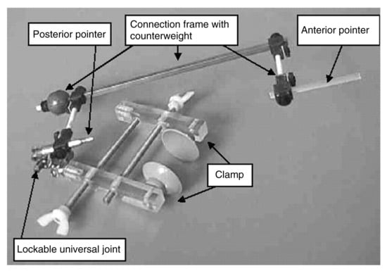
Figure 1.
The subtalar joint axis locator consists of a clamping system that attaches to the calcaneus, which is connected to a frame that contains an anterior and a posterior pointer. These pointers can be aligned independent of the clamping system and can be directed at the anterior and posterior exit points of the subtalar joint axis.
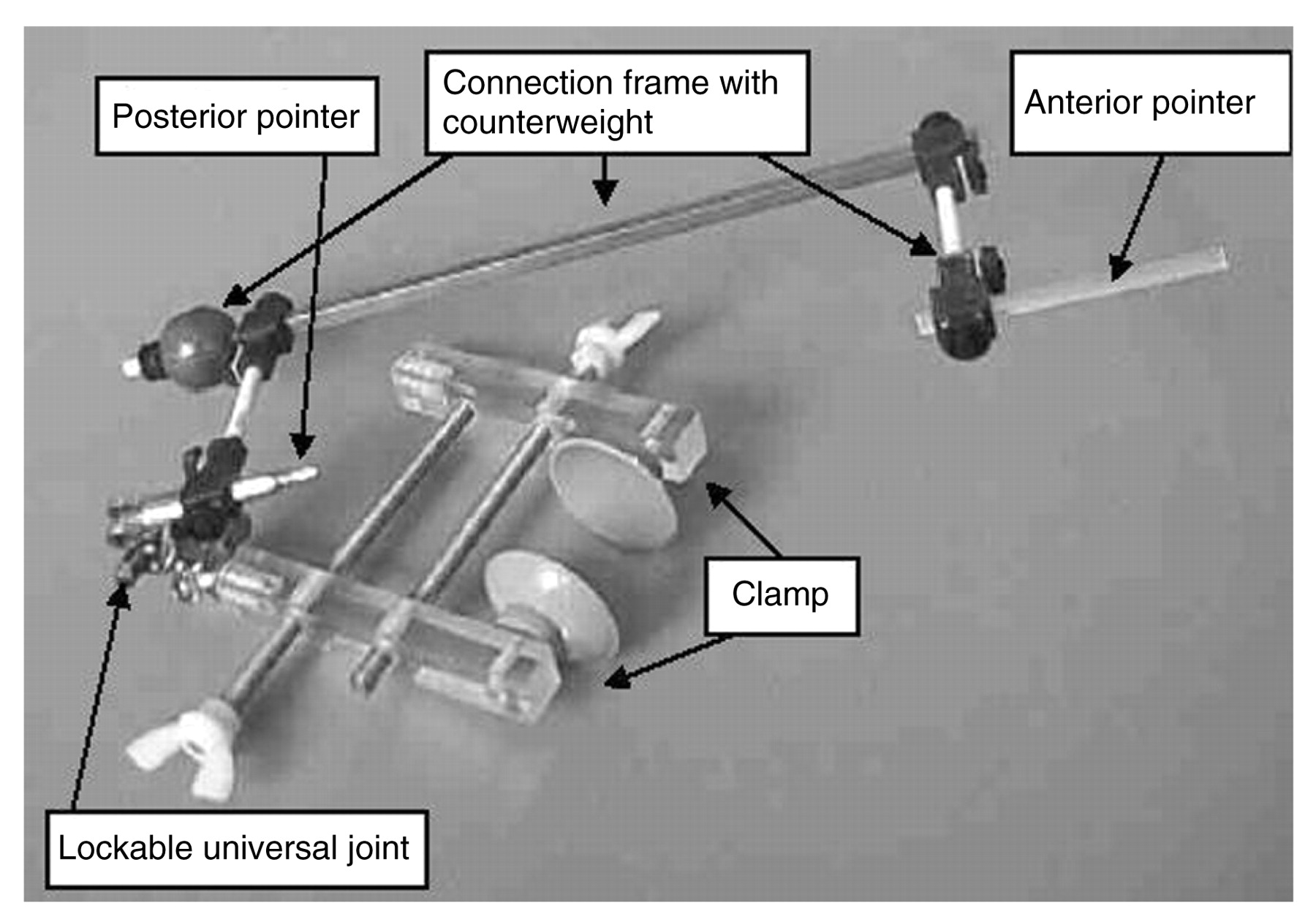
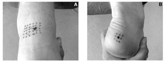
Figure 2.
Identification of the anterior (A) and posterior (B) exit points of the subtalar joint axis using the technique described by Morris and Jones.[16]
Positioning the Subtalar Joint Axis Locator
With the subject weightbearing, the clamping system of the SJAL was secured to the medial and lateral aspects of the calcaneus. The pointers were then positioned so that they were directly in line with the anterior and posterior exit points of the subtalar joint axis (Fig. 3). As a further check of the alignment of the SJAL relative to the subtalar joint axis, the foot was put through pronation and supination motions of the subtalar joint while the subject was supine on an examining table. Good alignment of the pointers of the SJAL was assumed to be present when pronation and supination motions of the subtalar joint produced a rotational motion of the pointers of the SJAL only along their long axes (ie, the pointers were spinning along their own axes).
Radiographic Study
Dorsoplantar radiographs were taken with the subject in three rotational positions of the subtalar joint: maximally pronated, relaxed calcaneal stance, and maximally supinated (Fig. 4). The central beam of the radiography unit was angulated 10° from the frontal plane in a superoanterior-to-inferoposterior direction. This was the closest that the head of the radiography unit could be positioned to the subjects without causing them to stand in an unnatural position. The posterior and anterior pointers of the SJAL measure 4 mm in diameter at their widest point and taper to 1 mm at their narrow pointing end. Because the pointers are radiopaque and relatively narrow, visualization of the anterior and posterior pointers of the SJAL relative to the osseous structures of the foot was easy. To assess the magnification of the anterior pointer of the SJAL on the radiographs, the width of the anterior pointer of the SJAL and the image of this pointer on the radiographs were measured using a micrometer. The anterior pointer was found to be magnified by a factor of 1.2 on the radiographs. Although the problems of magnification are acknowledged to potentially affect measurements in radiographic studies, the anterior pointer of the SJAL and the talus were in such close approximation to each other anatomically that these factors probably had minimal effect on the measurements made in this study.
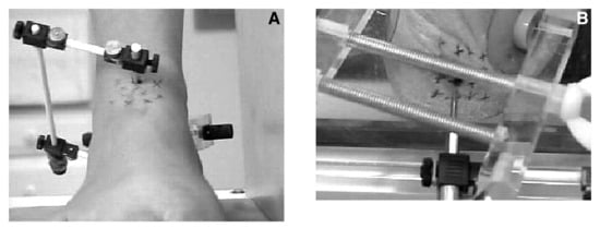
Figure 3.
The subtalar joint axis locator is positioned on the subject’s foot while weightbearing, the clamping system is secured to the medial and lateral calcaneus, and the pointers are then aligned and directed at the anterior (A) and posterior (B) exit points of the subtalar joint axis.
The radiographs were measured as follows: the most medial and the most lateral aspects of the talar head were determined, and then a talar head line was drawn to connect these points. The anterior pointer of the SJAL was then bisected, and its line was extended posteriorly. The measured distance of the anterior pointer bisection line along the talar head line, from left to right, served as a reference for the relative position of the pointer to the talar head (Fig. 5 and Table 1).
Dynamic Use
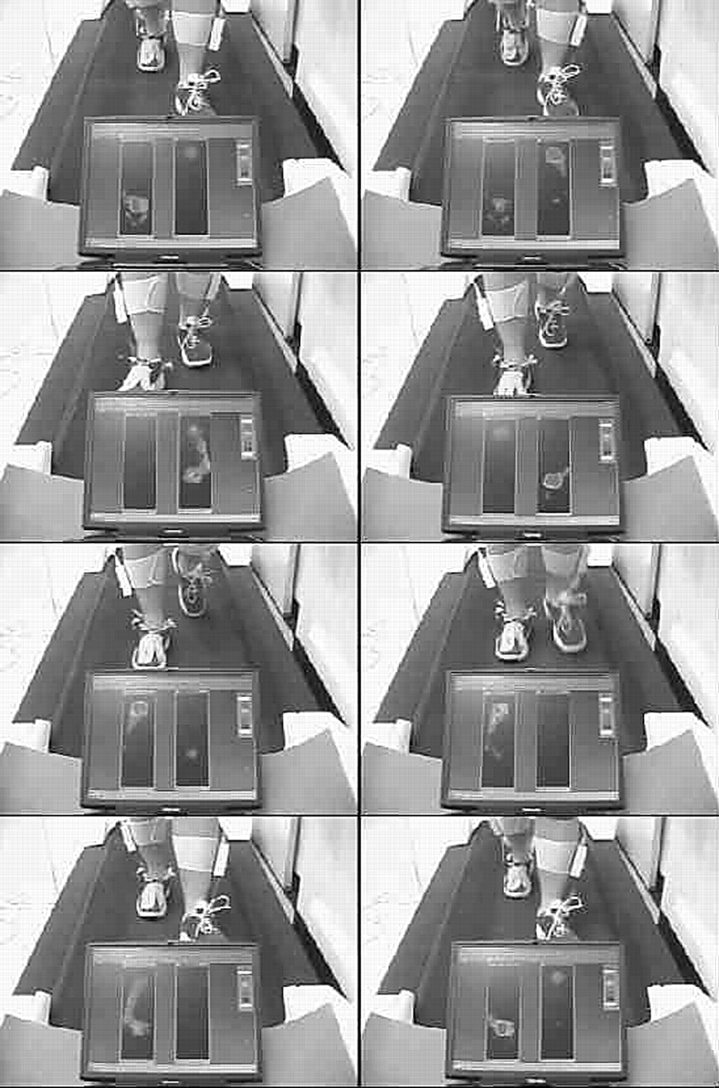
One of the objectives of this study was to develop an instrument that would allow tracking of the spatial location of the subtalar joint axis in three dimensions during weightbearing function. The radiographic study described previously here tested the use of the instrument in a static situation. To confirm that the instrument could be used in a true dynamic situation, we performed several basic dynamic studies with the device in situ, including walking barefoot and walking in modified footwear (Figs. 6–8).
Results
The results of the radiographic study showed that the position of the anterior pointer relative to the talar head did not change with rotation of the foot from maximally pronated to relaxed calcaneal stance and then to maximally supinated (Table 1). In other words, there was no displacement error between the motions of the anterior pointer of the SJAL and the talar head in any of the three subtalar joint positions.
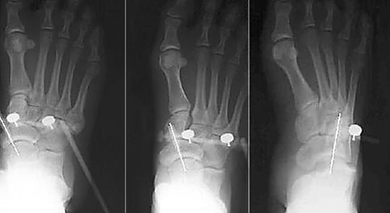
Figure 4.
Dorsoplantar radiographs of one subject’s foot in three rotational positions of the subtalar joint: maximally pronated (left), relaxed calcaneal stance (center), and maximally supinated (right).
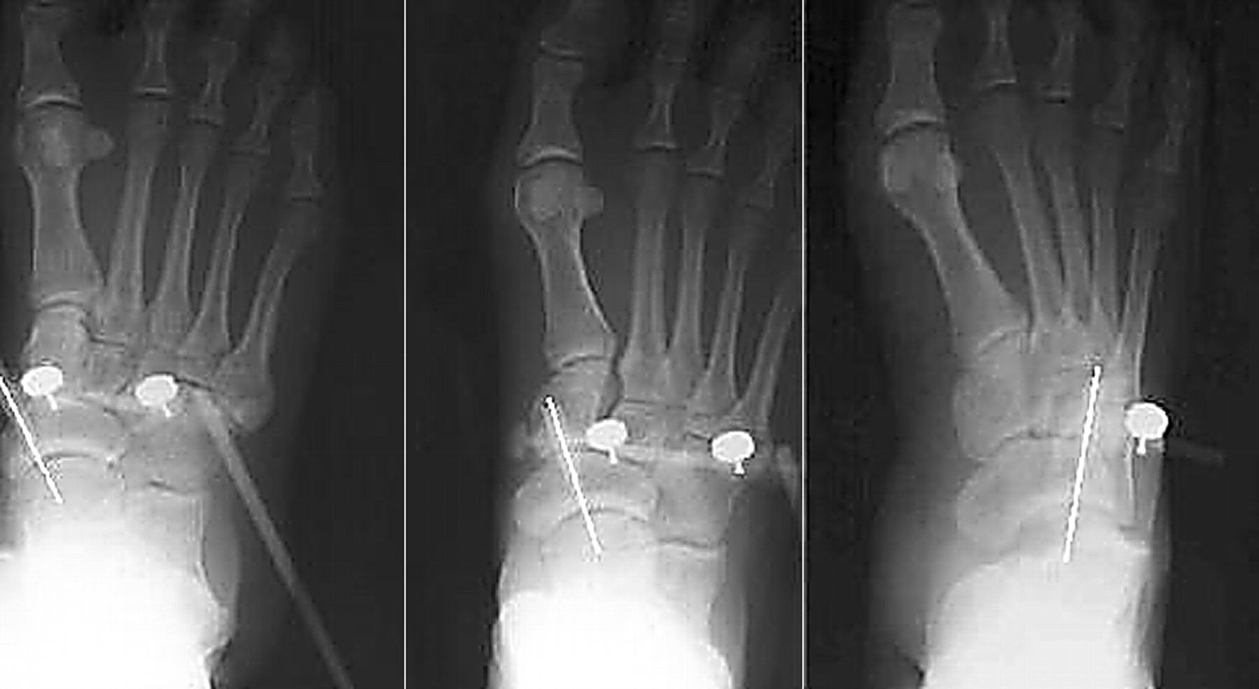
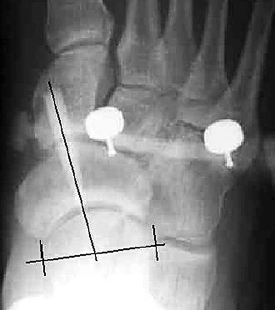
Figure 5.
The technique used to measure the radiographs involved drawing a talar head line across the talar head from its most medial to its most lateral aspect, bisecting the anterior pointer, and extending this bisection to the talar head line. Then the distance, from left to right, along the talar head line is measured to determine the relative position of the anterior pointer to the talar head.
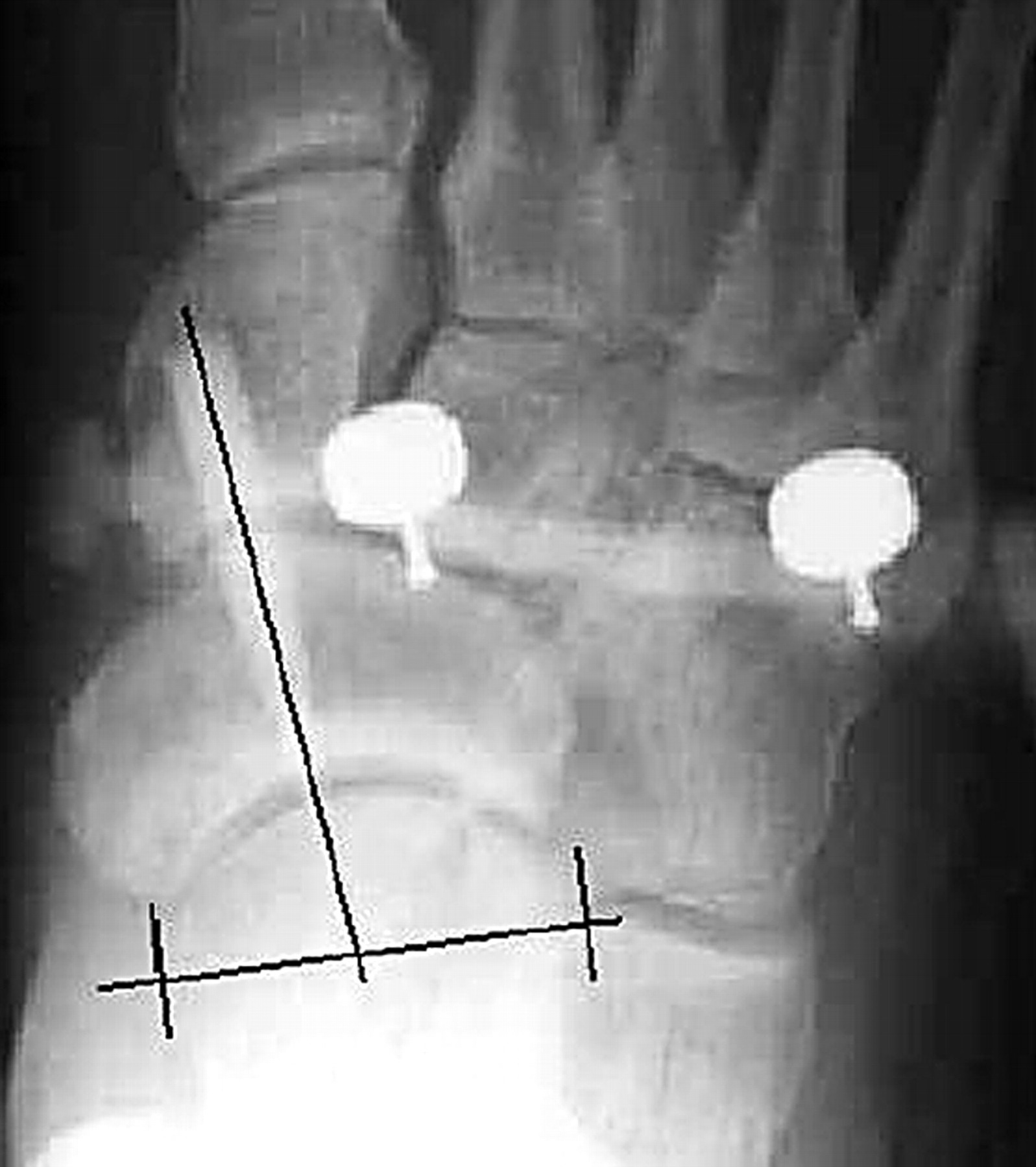

Table 1.
Position of the Anterior Pointer of the Subtalar Joint Axis Locator Relative to the Talar Head
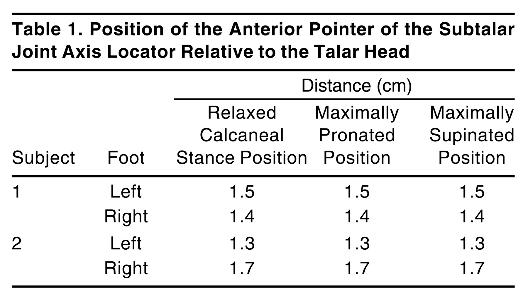
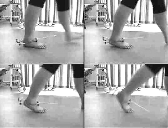
Figure 6.
Lateral view of the subtalar joint axis locator on the right foot of a patient shows the movements of the subtalar joint axis in the sagittal plane.
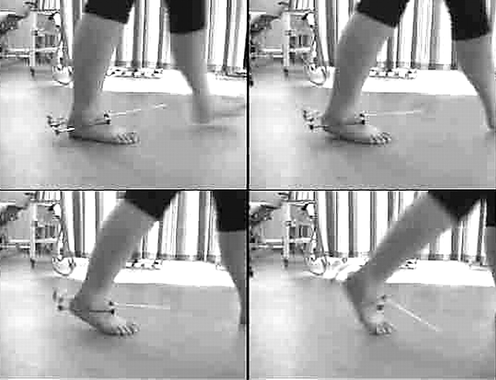
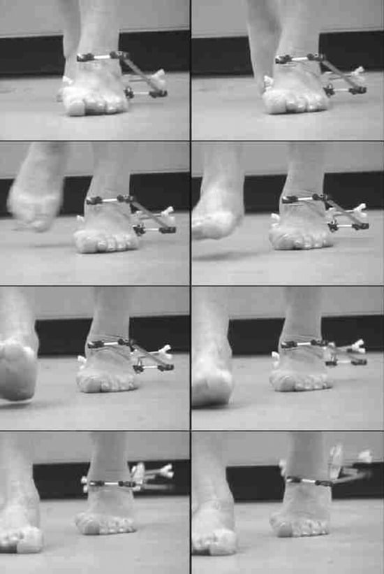
Figure 7.
Anterior view of the subtalar joint axis locator on the left foot of a patient with a severely pronated foot with posterior tibial tendinitis shows the progressive medial location of the subtalar joint axis as the patient progresses into the late midstance phase of gait.
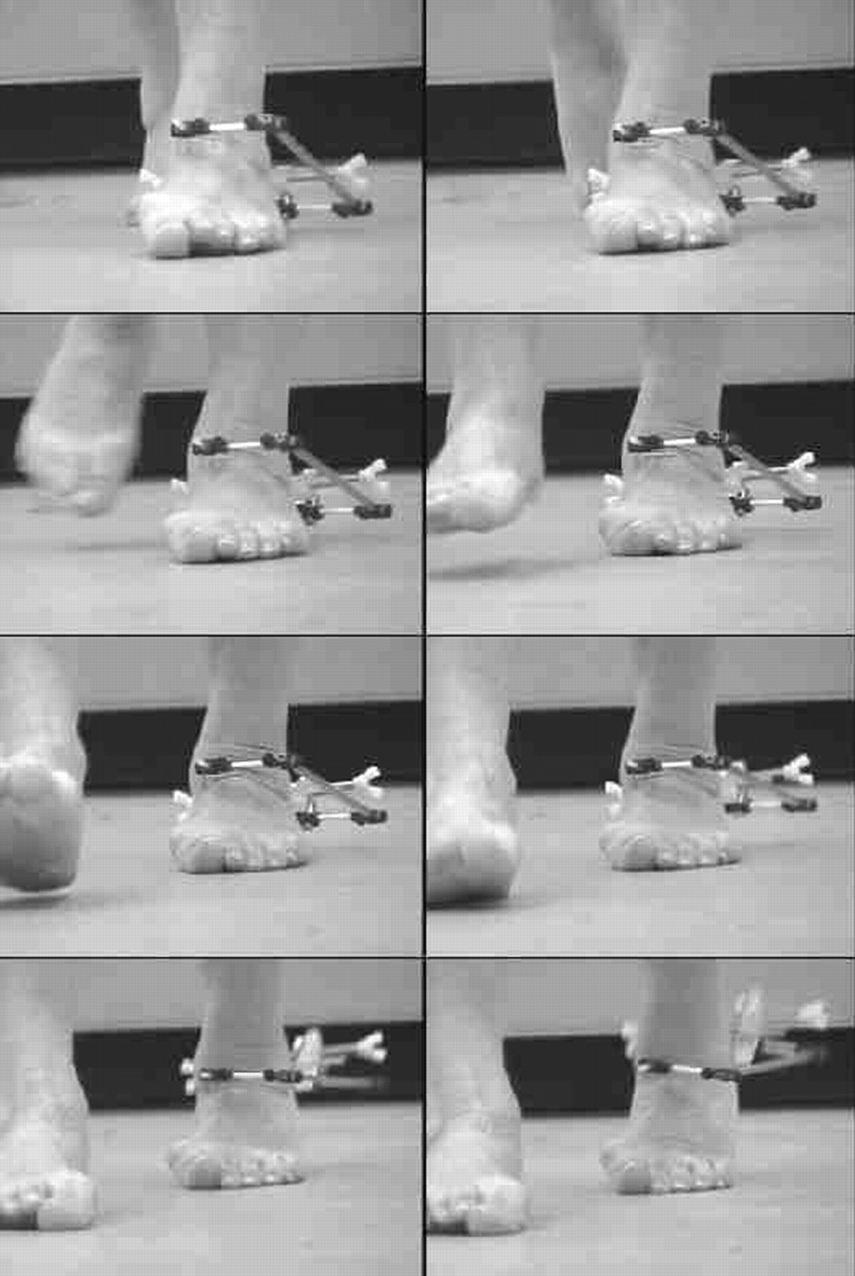
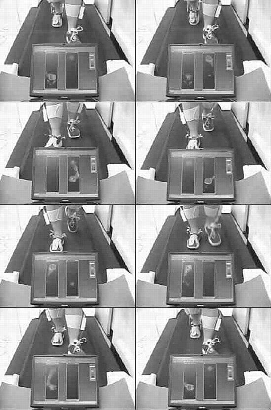
Figure 8.
Anterior view of the subtalar joint axis locator on the right foot of a patient wearing modified footwear. An in-shoe pressure-measurement device is in situ, providing a crude estimation of the position of the center of pressure relative to the subtalar joint axis location.
Discussion
Although the sample used in this preliminary study was too small to draw definitive conclusions, the results obtained from the two subjects used in the radiographic study were very encouraging. Once positioned properly, the SJAL accurately tracked a point on the talar head in both subjects with zero displacement error even though the SJAL was physically attached only to the calcaneus.
When weightbearing rotation occurred at the subtalar joint in the two subjects, the SJAL pointers moved because the clamping system of the SJAL was secured to the medial and lateral aspects of the calcaneus. The talar head was free to move independent of the pointers because the pointers of the SJAL were not physically attached to the talus. These preliminary results suggest that when the anterior pointer of the SJAL moves in response to calcaneal motion, the pointer stays in a constant position relative to the talar neck in the transverse plane. This was even more evident during nonweightbearing examination of the foot when the SJAL was in place and the foot was rotated about the subtalar joint relative to the tibia. In these open-kinetic-chain rotational movements of the subtalar joint, the rotational motions of the calcaneus and the anterior pointer of the SJAL occurred around a single point on the anterodorsal neck of an apparently immobile talus. This indicated that the SJAL was accurately tracking a single point on the talus that, according to our experimental findings, was the anterior exit point of the subtalar joint axis from the talus.
If, however, the talus and the calcaneus were not rotating around the axis defined by the SJAL pointers, subtalar joint rotation would have produced a rotational movement of the pointer relative to the subtalar joint axis. The rotational movement of the talus relative to the pointer would have been apparent by a change in position of the SJAL relative to the talar head in our measurements. Because the distance that an object travels along a circular path is equal to the mathematical product of the arc of its motion in radians and its distance from the axis of rotation, in our experiment, the greater the distance of the SJAL pointer from the actual axis of rotation of the subtalar joint, the greater would have been the error between the pointer and the talar head as the foot moved from maximum pronation to maximum supination. Because there was no observable difference between the talar head and the SJAL pointer in our study, one can reasonably assume that the SJAL was very close to tracking the actual spatial location of the subtalar joint axis from maximum pronation to maximum supination.
From our work with the SJAL, it is clear that the spatial location of the subtalar joint axis is dynamic, not fixed in space as earlier researchers believed.[9–11] The dynamic excursion of the subtalar joint axis in three dimensions during gait is likely to be an important contributor to the mechanical variability of foot function from one individual to another. Green and Carol[19] described the concept of planal dominance that links the motion available in each cardinal plane at a joint with the position of the joint’s axis. The greater the angle formed between the axis and the plane of motion, the more motion will occur in that plane. It is clear that as the spatial location of the subtalar joint axis changes, so too will the planal dominance of the subtalar joint change.
In addition, the spatial location of the subtalar joint axis may vary widely when the foot moves from maximum pronation to maximum supination during weightbearing rotations of the foot. The main contemporary textbooks on the biomechanics of the foot and ankle show a subtalar joint axis that is angled from posterolateral to anteromedial relative to the foot. However, it is evident that this may not always be correct for all rotational positions of the subtalar joint. In Figure 4, the image on the left shows the foot in a maximally pronated position, with the subtalar joint axis angled from posterolateral to anteromedial; however, in the image on the right, when the foot is maximally supinated, the axis can be seen to pass anterolaterally rather than anteromedially.
The synchronous change in subtalar joint axis spatial location with changes in the rotational position of the subtalar joint has been described previously by Kirby.[6] These changes in subtalar joint axis spatial location relative to the external forces acting on the foot from ground reaction force and relative to the anatomical locations of the insertion points of muscles acting on the foot have a profound mechanical influence on the subtalar joint moments produced during weightbearing activities.[1–7]
For example, when the foot in Figure 4 is maximally pronated and all of the metatarsal heads are lateral to the subtalar joint axis, ground reaction force acting on any of the metatarsal heads results in a subtalar joint pronation moment. However, when the same foot is maximally supinated and the subtalar joint axis passes between the fourth and fifth metatarsal heads, any ground reaction forces acting on the first through fourth metatarsal heads will produce a subtalar joint supination moment because they are medial to the subtalar joint axis, whereas ground reaction forces acting at the fifth metatarsal head will produce a subtalar joint pronation moment because it is positioned lateral to the axis. Therefore, in this foot, moving from the maximally pronated position to the maximally supinated position would change the mechanical effect of ground reaction forces acting plantar to the first metatarsal head from a strong subtalar joint pronation moment to a strong subtalar joint supination moment. These large changes in the spatial location of the subtalar joint axis invariably occur with rotations of the subtalar joint, and with variations in the geometry of the foot skeleton, and cause many of the abnormal rotational forces (ie, moments) in the joints of the foot that cause many of the mechanically based pathologies of the foot and lower extremity.[1–6]
One of the main possible benefits of the SJAL is that it may be used to assess the subtalar joint spatial location dynamically during weightbearing activities (Figs. 6–8). Our testing showed that the device could track the dynamic excursion of the subtalar joint axis in three dimensions during gait. This allowed better appreciation of the spatial movements and temporal movement patterns of the subtalar joint axis during the gait cycle. Replacing the anterior and posterior marker of the SJAL with markers from a motion-analysis system and linking this kinematic data with the kinetic data from a force plate could provide more precise information regarding the magnitude of moments acting on the subtalar joint during gait.
Any abnormal movements or abnormal temporal movement patterns of the subtalar joint axis during dynamic function are likely to increase the mechanical stress on the tissues that limit subtalar joint motion, and this may, in turn, result in musculoskeletal pathology.[5,6] Because the magnitude of stress in the tissues that restrain a joint at the ends of its range of motion is increased when the joint approaches that end range of motion, the magnitude of tissue stress in these restraining structures will necessarily decrease when the joint is functioning in its midrange position.[5] With this in mind, any treatment approach that attempts to limit the extreme excursions of the subtalar joint rotational position and the subtalar joint spatial location, and that attempts to normalize their temporal movement patterns, should be capable of reducing tissue stress around the joint, thus improving symptoms caused by increased magnitudes of tissue stress. The ability of the SJAL to track the spatial movements and the temporal movement patterns of the subtalar joint axis during gait in a clinical environment may, therefore, assist the clinician with the prescription of functional foot orthoses and other mechanical therapies.
The SJAL may help us predict and understand pathology caused by abnormal subtalar joint supination moments. For example, in the foot shown in Figure 4, as the subtalar joint becomes increasingly supinated, such as during propulsion, the subtalar joint axis will shift more laterally in relation to the forefoot, which will cause an increase in subtalar joint supination moments caused by ground reaction forces. Because excessive subtalar joint supination moment magnitudes may lead to inversion sprains of the ankle, sufficient subtalar joint pronation moment magnitudes need to be generated from some source to counteract them to avoid inversion ankle injuries during propulsion. A counterbalancing of subtalar joint supination moments may be possible only through the subtalar joint pronation moments caused by ground reaction forces acting on the fifth metatarsal head or through contractile activity of the peroneus longus or peroneus brevis muscles. The subtalar joint axis location and rotational equilibrium theory of Kirby[6] predicts that feet that display lateral deviation of the subtalar joint axis are prone to supination-related pathology. Perhaps unsurprisingly, the subject illustrated in Figure 4 reported a history of peroneal tendinitis and inversion sprains of the ankle.
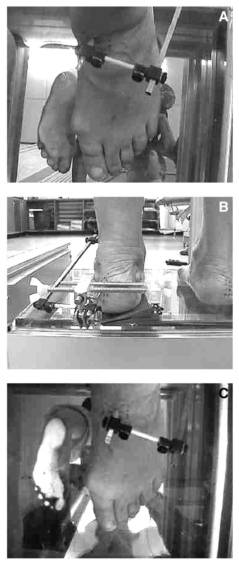
The SJAL may also be used to evaluate the abnormal subtalar joint moments that occur in patients with severely pronated feet. A dynamic study of a patient with a significantly medially deviated subtalar joint axis showed that no resupination of the subtalar joint occurred during the propulsive phase of walking (Fig. 7). In this patient, the subtalar joint axis passed over the medial border of the foot, with all of the metatarsal heads being located lateral to the axis so that any ground reaction forces acting on the forefoot would produce a large magnitude of subtalar joint pronation moment. The subtalar joint axis location and rotational equilibrium theory[6] predicts that this patient should be predisposed to pronation-related pathology. In addition to the obvious hallux valgus deformity noted, the patient reported symptoms and had clinical findings consistent with posterior tibial tendinitis. With the patient in the relaxed standing position, varus wedging was added incrementally beneath the heel in an attempt to supinate the subtalar joint and shift the subtalar joint axis laterally into a more “normal” alignment as described by Kirby[1–3] (Fig. 9A). A total of 15° of varus wedging was added before an observable shift in axis position occurred. A total of 18° of wedging was needed to direct the axis into a “normal”[1–3] alignment (Fig. 9 B and C). The patient was prescribed a 3-mm polypropylene device with an 18°, 5-mm medial heel skive that resulted in vast improvement in the patient’s posterior tibial tendinitis symptoms.
From the discussion of these two clinical examples, it becomes evident that the SJAL may prove to be helpful in recognizing the spatial movements and temporal movement patterns of the subtalar joint axis during dynamic function in patients with mechanically related pathology of the foot and lower extremity. Therefore, the SJAL could be a useful tool in the prevention and treatment of foot and lower-limb pathology. In addition, the potential ability of the SJAL to allow researchers to combine the spatial and temporal movement patterns of the subtalar joint axis along with ground reaction force data from force-plate analysis may add considerably, in the future, to our understanding of normal and abnormal foot and lower-extremity function during weightbearing activities. Further trials of the instrument are required in many more subjects before its reliability and validity can be better determined for all foot types and all types of weightbearing activities.
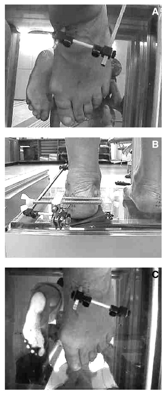
Figure 9.
With the patient from Figure 7 in the relaxed standing position (A), varus wedging was added incrementally beneath the heel to supinate the subtalar joint and shift the subtalar joint axis laterally into a more “normal” alignment as described by Kirby[1–3]; a total of 15° of varus wedging was added before an observable shift in axis position occurred. A total of 18° of wedging was needed to direct the axis into a “normal”[1–3] alignment (B and C).
Conclusion
In a preliminary radiologic study of two adults, the SJAL was accurate at tracking the talar neck position during weightbearing rotational motions of the subtalar joint even though the SJAL was physically attached only to the calcaneus. It is possible, then, that the SJAL can reliably track the spatial location of the subtalar joint axis during weightbearing movements of the foot. The SJAL has also been successfully applied clinically in preliminary dynamic studies. As a result, the SJAL may have applications as a research tool and as an aid to foot orthosis prescription in the clinical environment. We hope that this preliminary study stimulates more research on possible experimental or clinical applications of the SJAL and on whether the device can aid in understanding and improving the treatment of musculoskeletal disorders of the foot and lower extremity.
References
- Kirby KA: Methods for determination of positional variations in the subtalar joint axis. .JAPMA77::228. ,1987. .
- Kirby KA: Rotational equilibrium across the subtalar joint axis. .JAPMA79::1. ,1989. .
- Kirby KA: The medial heel skive technique: improving pronation control in foot orthoses. .JAPMA82::177. ,1992. .
- Kirby KA, Green DR: “Evaluation and Non-operative Management of Pes Valgus,” in Foot and Ankle Disorders in Children, ed by S DeValentine, p 295, Churchill Livingstone, New York. ,1992. .
- Fuller EA: Center of pressure and its theoretical relationship to foot pathology. .JAPMA89::278. ,1999. .
- Kirby KA: Subtalar joint axis location and rotational equilibrium theory of foot function. .JAPMA91::465. ,2001. .
- Menz HB: Clinical measurement of the lower extremity: where to from here?. Australas J Podiatr Med31::95. ,1997. .
- Pierrynowski MR, Finstad E, Kemecsey M, et al: Relationship between the subtalar joint inclination angle and the location of lower-extremity injuries. .JAPMA93::481. ,2003. .
- Manter JT: Movements of the subtalar and transverse tarsal joints. .Anat Rec80::397. ,1941. .
- Root ML, Weed JH, Sgarlato TE, et al: Axis of motion of the subtalar joint. .JAPMA56::149. ,1966. .
- Close JR, Inman VT, Poor PM, et al: The function of the subtalar joint. .Clin Orthop Relat Res50::159. ,1967. .
- Van Langelaan EJ: A kinematic analysis of the tarsal joints: an X-ray photogrammetric study. .Acta Orthop Scand Suppl204::1. ,1983. .
- Phillips RD, Christeck R, Phillips RL: Clinical measurement of the axis of the subtalar joint. .JAPMA75::119. ,1985. .
- Phillips RD, Lidtke RH: Clinical determination of the linear equation for the subtalar joint axis. .JAPMA82::1. ,1992. .
- Lundberg A, Svensson OK: The axes of rotation of the talocalcaneal and talonavicular joints. .The Foot3::75. ,1993. .
- Morris JL, Jones LJ: New techniques to establish the subtalar joint’s functional axis. .Clin Podiatr Med Surg11::301. ,1994. .
- Nester CJ: Review of the literature on the axis of rotation at the subtalar joint. .The Foot8::111. ,1997. .
- Van Den Bogert AJ, Smith GD, Nigg BM: In vivo determination of the anatomical axes of the ankle joint complex: an optimization approach. .J Biomech27::1469. ,1994. .
- Green DR, Carol A: Planal dominance. .JAPA74::98. ,1984. .
© 2006 American Podiatric Medical Association