


Abstract
Recent debate and literature have provided impetus to the growing body of thought that we should not model the midtarsal joint as having two simultaneous axes of rotation but as having a single instantaneous axis of rotation. Building on this concept, we present new reference terminology and propose that descriptions of midtarsal joint kinetics and kinematics relate to moments and motion in the cardinal body planes as defined by the x-, y-, and z-axes of the local reference system of the calcaneus. This replaces the existing terminology that describes the oblique and longitudinal axes for the midtarsal joint. The purpose of the new terms of reference and terminology is to aid in the communication of ideas and concepts regarding the biomechanics of the midtarsal joint among clinicians and between researchers and clinicians. It will also allow integration of the midtarsal joint into the emerging biomechanical model of the lower limb, promote consistency in discussions of the joint, and ease understanding of the interrelationships between the kinetics and the kinematics of the articulations in the foot and lower limb and their relationship to pathology and clinical practice. (J Am Podiatr Med Assoc 96(1): 24–31, 2006).
In a previously published study,[1] we showed that the model of the midtarsal joint that comprises two axes of rotation (longitudinal and oblique) is unsound because it conflicts with basic concepts of rigid-body kinematics. Contemporary data have shown that it is possible to describe the kinematics of the midtarsal joint by modeling the navicular and cuboid bones as one rigid body moving relative to the calcaneus, and under such conditions the rotation of this body relative to another can occur only around one instantaneous axis of rotation. Although these new data do not form a new model of the midtarsal joint, they demonstrate that it is possible to describe the characteristics of the midtarsal joint using one axis of rotation at any one instant in time, and these data supersede the oblique and longitudinal axes of rotation. These data add further substance to the growing body of opinion suggesting that we move away from the two-axis model of the midtarsal joint.[2–4] These recent developments form the basis of the present article, which presents a description of reference terms intended for future clinical modeling of the midtarsal joint. Importantly, this new terminology provides a link between research into the kinematics and kinetics of the midtarsal joint and the clinical theories about the development and management of foot and leg disorders related to biomechanics. The use of existing terms of reference and associated terminology, the oblique and longitudinal axes, has been a major barrier to the transfer of knowledge between research and clinical practice because researchers and clinicians have been using different terms of reference and terminology. The terms of reference and terminology proposed in this article should be integrated into our conceptual models of how altered biomechanics of the foot can have a role in the development of foot and lower-limb pathologies, replacing the longitudinal and oblique axes of rotation in these clinical models. After this integration of new terms of reference and terminology into our conceptual, clinically focused models of foot function, they should be integrated into future literature, teaching materials, research design, and the principles of orthosis design.
In the presentation of new terms of reference and terminology, clarity in definitions is paramount. The term midtarsal joint refers to the articulation of the rigid body formed by the navicular and cuboid bones relative to the talus and calcaneus. The navicular and cuboid bones can be considered one rigid body because, although there is some relative motion between the two, they always move principally in the same direction.[5,6] For example, when the navicular bone everts relative to the ground, so too does the cuboid bone, and vice versa for inversion, and likewise with dorsiflexion/plantarflexion and adduction/ abduction. The fact that one bone rotates to a greater degree than the other can be ignored for the purposes of modeling because it allows us to considerably reduce the complexity of the description of the midtarsal joint without compromising the relevance of the rigid-body model to the actual situation. It should be remembered that modeling is the systematic and rationalized reduction in complexity of a complex system so that its form or function can be better investigated and understood. However, the process of reducing the complexity of a complex system must ensure that the characteristics of the final model adequately represent the original complex system. Modeling, however, is very much context-driven. For example, anatomists would prefer to keep the talonavicular and calcaneocuboid joints separate because the context for their work is the physical form and how it relates to the function of the two joints. The clinical perspective is much different, being defined by what we can see and feel in the foot. Clinically, the talonavicular and calcaneocuboid joints are inseparable, and because there is some scientific basis to the argument, it is reasonable to reduce the complexity of the midtarsal joint by considering the talonavicular and calcaneocuboid joints collectively as one functional unit. Considering the navicular and cuboid bones as a rigid body reduces the complexity of the midtarsal joint yet maintains the relevance of the model to the context of clinical practice.
To further clarify this definition, it should be made clear that the term midtarsal joint does not refer to the motion of the forefoot relative to the rearfoot or to the motion of the plane of the plantar aspect of the metatarsal heads relative to the plane of the plantar aspect of the rearfoot (generally referred to as the forefoot-rearfoot relationship). These motions are a combination of the motion at the subtalar and midtarsal joints plus the motion within the navicular-cuboid-cuneiform-metatarsal complex. Thus the midtarsal joint is not solely responsible for the weightbearing forefoot-rearfoot relationship because the joints between the navicular-cuboid segment and the plane of the metatarsal heads are capable of motion that enables the plane of the metatarsal heads to move independently of the navicular-cuboid segment. Midtarsal joint motion is not synonymous with the forefoot-rearfoot relationship.
The purpose of the new terms of reference and terminology is to aid in the communication of ideas and concepts regarding the biomechanics of the midtarsal joint among clinicians and between researchers and clinicians. It will also allow integration of the midtarsal joint into the emerging biomechanical model of the lower limb,[7] promote consistency in discussions of the joint, and ease understanding of the interrelationships between the kinetics and the kinematics of the articulations in the foot and lower limb and their relationship to pathology and clinical practice. Updating our terms of reference and terminology, and rejecting inappropriate terms of reference and terminology, is key to the continued development of our understanding of foot biomechanics and the use of orthotic interventions in podiatric medical practice.
New Terms of Reference and Terminology
It has already been established that the motion at the midtarsal joint can be described as having, for any given instant in time, a single instantaneous axis of rotation and that over time this axis varies in position and orientation.[1] Related works[5,6,8] on the individual talonavicular and calcaneocuboid joints add further to this important concept. The midtarsal joint axis describes the motion of the navicular and cuboid bones as one rigid body relative to a reference system that defines the sagittal, frontal, and transverse planes in which the midtarsal joint motion is described. In a previous work,[1] this reference frame was based in the calcaneus. The reference system forms the basis of how we describe the midtarsal joint; it defines our terms of reference and terminology. It is this reference system that is the core topic of this article. In modeling the motion at the midtarsal joint (or, indeed, any human joint) using rigid-body kinematics, we have three main choices as to the reference system we choose.
Option 1
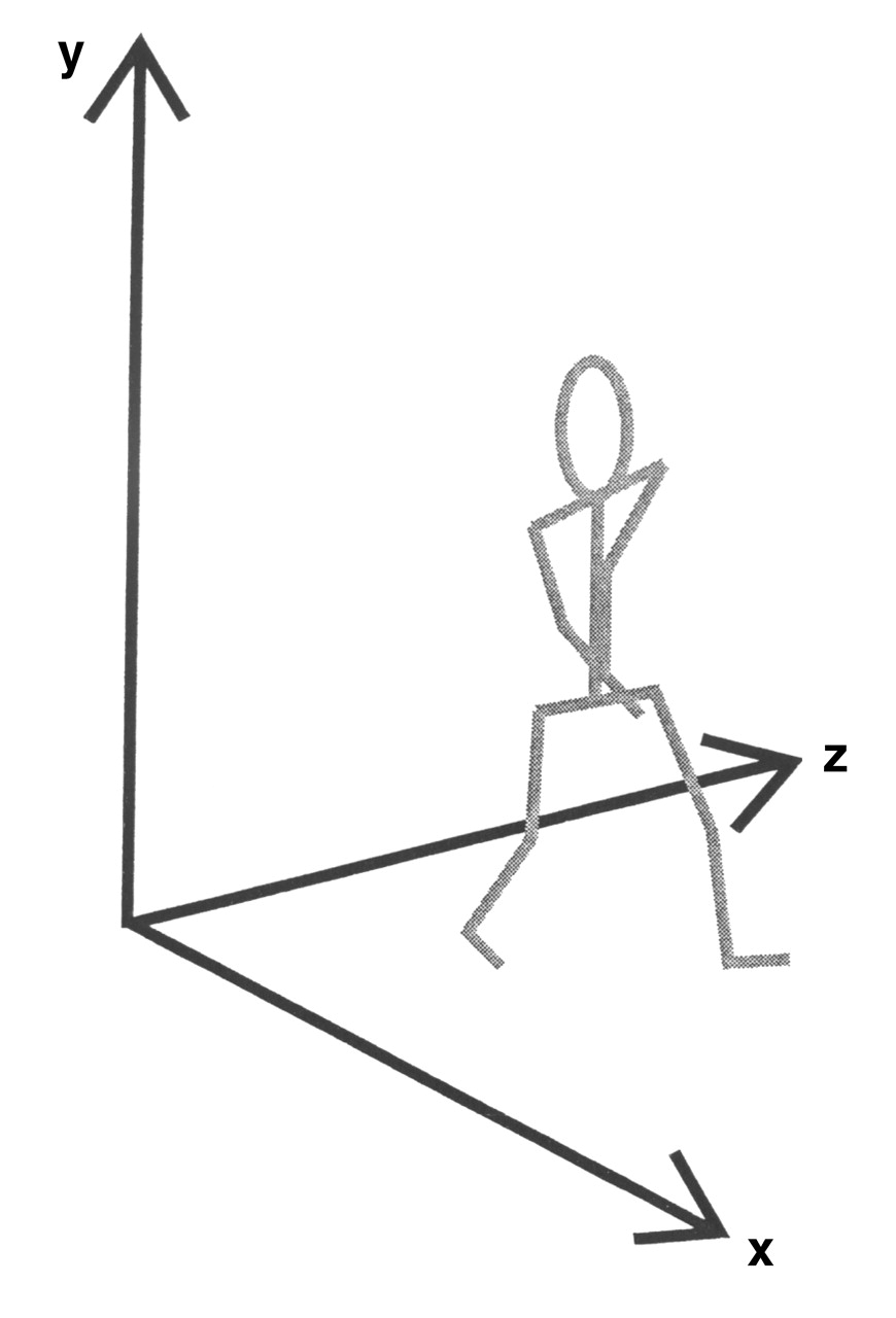
First, we may reference the motion of the navicular and cuboid bones relative to the global reference system. The global reference system consists of the three cardinal body planes defined by the x-, y-, and z-axes and is fixed relative to the environment (Fig. 1). The fact that it is fixed in position creates a significant problem during the description of movements such as walking because most movements between different body segments take place in planes that are different from the planes of the global reference system. Thus the planes of the global reference system have little anatomical relevance in relation to the joints. This is why two-dimensional analysis of the frontal plane motion between the heel and the leg is inaccurate; the camera records a view of the heel-to-leg motion in the frontal plane of the global reference system, yet the motion we need to describe occurs not in this plane but in the frontal plane of the leg.
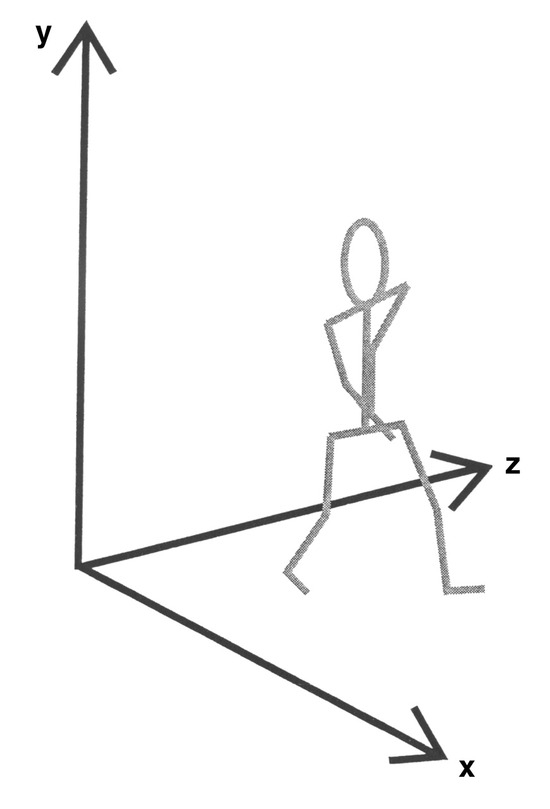
Figure 1.
The x-, y-, and z-axes of the global reference system, which is fixed relative to the environment.
Option 2
An alternative to the global reference system is the joint coordinate system, which has been used to describe knee kinematics and is recommended by the International Society of Biomechanics.[9] This system uses the three cardinal body planes as defined by local coordinate systems in the proximal and distal segments of a joint (local coordinate systems consist of three orthogonal axes [x, y, and z] whose orientation and position in the global reference system represent the three-dimensional orientation and position of the segment to which they are attached) and combines them with a third “floating axis” to provide a reference system for the motion of the distal segment relative to the proximal segment. At the knee, for example, the joint coordinate system is defined using the z-axis (flexion/extension axis) of the local coordinate system for the thigh, the y-axis (internal/ external rotation axis) of the local coordinate system for the shank, and a third axis, the x-axis, that is floating and nonorthogonal to the z- and y-axes and represents the axis around which the frontal plane motion occurs (Fig. 2). Importantly, because the axis system is derived from the location of the thigh and the shank, as these segments move, so too does the joint coordinate system, and some of the anatomical and clinical relevance of the reference system is preserved. The principal problem with the joint coordinate system is the difficulty associated with calculating moments around the three axes because they are not orthogonal. The nonorthogonal arrangement also makes their clinical interpretation difficult because clinicians are used to referring all motions to the cardinal body planes, which are based on an orthogonal axis system. Although it is experimentally useful, the clinical interpretation of joint coordinate system–based data is not always synergistic with clinical theory.
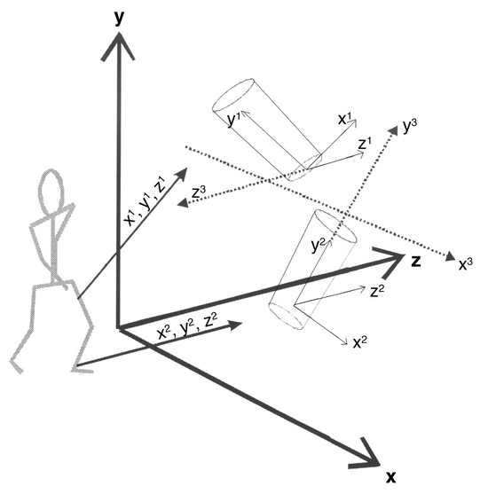
Figure 2.
Axes of the global reference system (x, y, and z), the local coordinate systems for the thigh (x1, y1, and z1) and the shank (x2, y2, and z2), and the joint coordinate system (x3, y3, and z3).
Option 3
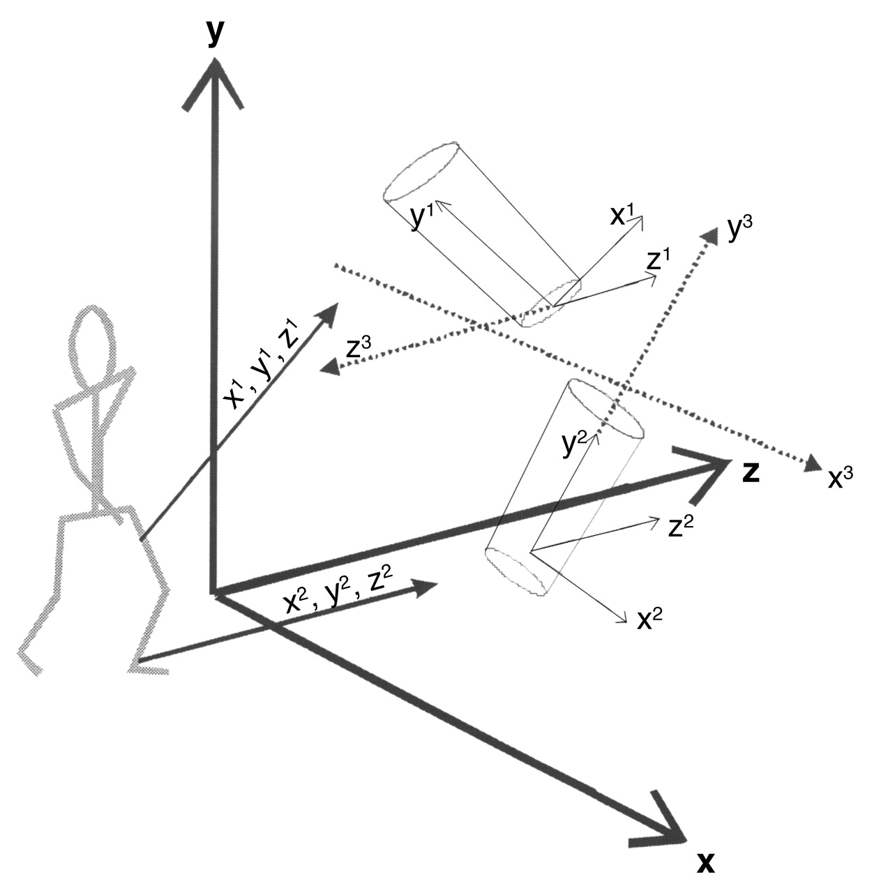
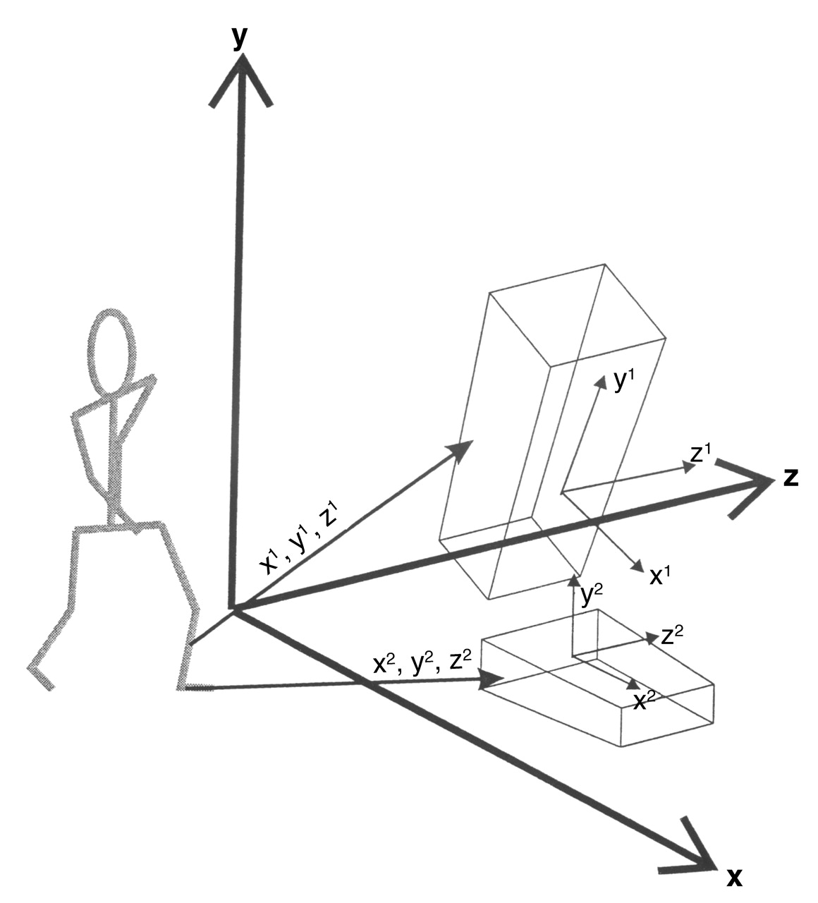
The third option is to describe the motion of the distal rigid body relative to the local coordinate system for the proximal rigid body. This means describing the motion of the distal segment as motion in the three cardinal body planes as defined in the proximal body segment (Fig. 3). In this case, like the joint coordinate system, the reference system moves as the body segments move through space, maintaining the anatomical relevance of the reference system. In addition, the axes remain orthogonal, and thus their clinical interpretation is much easier and is in line with our traditional understanding and description of body position and motion in orthogonal planes. Because we are seeking to provide terminology common to clinical practice and research, this is a considerable advantage.
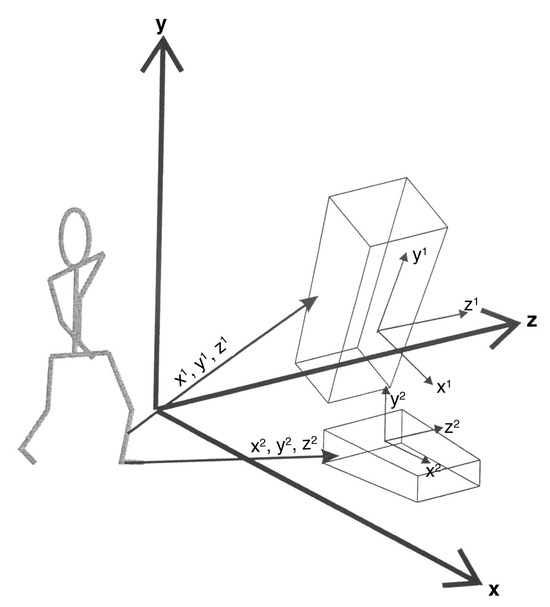
Figure 3.
Axes of the local coordinate systems for the shank (x1, y1, and z1) and the foot (x2, y2, and z2).
Each of the three reference systems has its merits and its application. The global reference system, for example, is the most useful way in which to describe motion of the pelvis during walking. The joint coordinate system makes intuitive sense for the knee. For the midtarsal joint, option 3, using the local coordinate system for the proximal segment as the reference system, seems most appropriate because it provides an essential link between research and clinical concepts of foot function. This option matches our traditional descriptions of joint motion in three orthogonal planes, has clear anatomical relevance, and yet can be easily defined experimentally. We are therefore recommending that the reference frame for the description of the biomechanics of the midtarsal joint be the local coordinate system for the calcaneus and the three cardinal body planes as defined in the calcaneus.
Local coordinate systems for a segment, such as for the shank for the distal segment of the knee, are defined using anatomically and clinically relevant landmarks on the body. For example, the local coordinate system for the thigh recommended by the International Society of Biomechanics is formed using the medial and lateral femoral epicondyles and the hip joint center, and the pelvis is defined using the two anterosuperior iliac spines and the two postero-superior iliac spines.[7] To define a local coordinate system for the calcaneus in which we can subsequently define the motion of the midtarsal joint, we must define suitable anatomical landmarks.
Because in experimental terms these landmarks are identified using externally (skin-) mounted devices, usually spherical reflective markers, there is a tendency to assume that landmarks are chosen on the basis of the likelihood of being able to attach a device or reflective marker to the landmark. In fact, the reverse should be the case, and landmarks should be chosen on the basis of the need to define a relevant reference frame. Having defined the desired orientation of the local coordinate system for the pelvis, thigh, and shank, there are well-recognized anatomical landmarks available to experimentally define the local coordinate system. This is not the case for the calcaneus, where there are no easily and reliably identified anatomical landmarks. In this case, we can still define a desired local coordinate system that has clinical relevance, but how it relates to the absolute position and orientation of the underlying anatomy is less clear than for the pelvis, thigh, and shank. By definition, then, at the moment, all we can measure is the relative motion of the calcaneus and the relative motion of the midtarsal joint.
Because we cannot have an anatomically relevant local coordinate system for the calcaneus and, therefore, the midtarsal joint (because there are no identifiable anatomical landmarks on the calcaneus and, therefore, we do not know its absolute position without some imaging data), we must create a local coordinate system that is of clinical relevance. The following is a description of the proposed orientation of the local coordinate system for the calcaneus and thus the axes around which midtarsal joint motion should be resolved and the cardinal body planes into which motion can be resolved (Fig. 4).
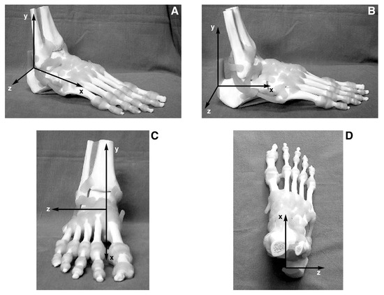
Figure 4.
A–D. The local coordinate system for the calcaneus shown from various angles.
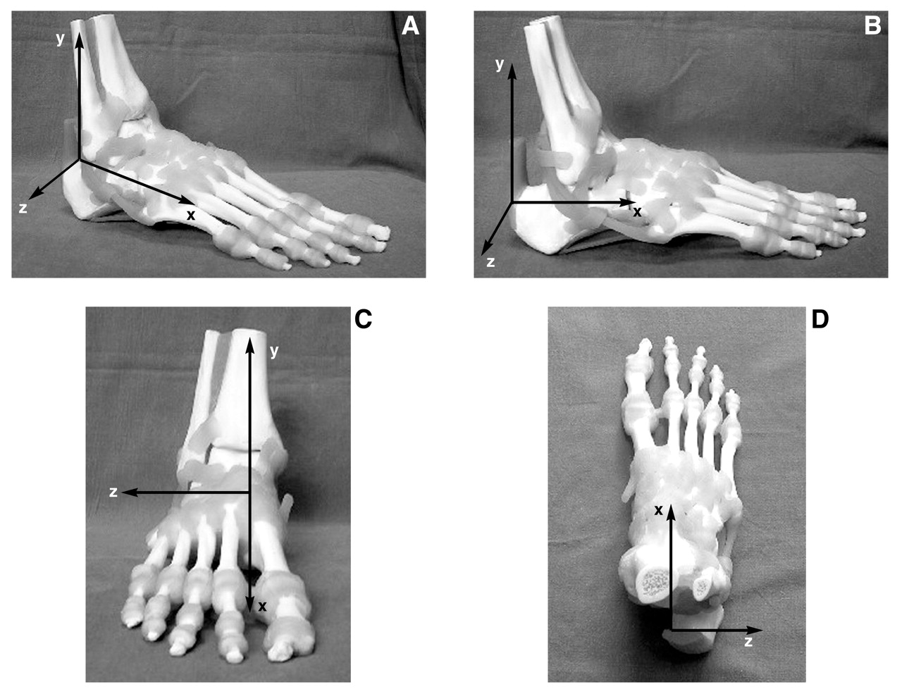
- The x-axis runs from anterior to posterior, is referred to as the anterior/posterior axis, and is parallel to a longitudinal bisection of the plantar surface of the calcaneus and to the supporting surface when a person stands in the standard anatomical position. The moments acting around this axis are referred to as inversion and eversion moments, which will produce frontal plane rotations of inversion and eversion.
- The y-axis runs from superior to inferior, is referred to as the vertical axis, and is oriented perpendicular to the supporting surface when a person stands in the standard anatomical position. The moments acting around this axis are referred to as adduction and abduction moments, which will produce transverse plane rotations of adduction and abduction.
- The z-axis runs from medial to lateral, is referred to as the medial/lateral axis, and is perpendicular to the x- and y-axes. The moments acting around this axis are referred to as dorsiflexion and plantarflexion moments, which will produce sagittal plane rotations of dorsiflexion and plantarflexion.
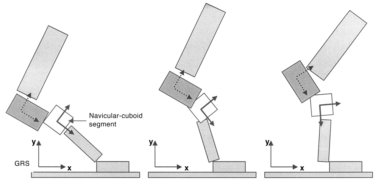
For illustrative purposes, the axes are fixed in length. The axes do not have a fixed anatomical location because their purpose is to define planes of motion into which the three-dimensional motion at the midtarsal joint can be resolved. Figure 5 illustrates how the reference system moves with the calcaneus during walking.
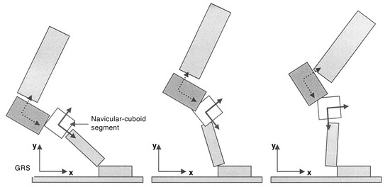
Figure 5.
Movement of the local coordinate system for the calcaneus and the navicular-cuboid segment that is the distal part of the midtarsal joint. The diagram illustrates how the systems change orientation during gait relative to the leg and to each other. GRS, global reference system.
Defining the Local Coordinate System Experimentally and Clinically
The local coordinate system proposed can easily be imaged clinically (Fig. 6), and this is sufficient to aid in the development and application of clinical models of normal and abnormal foot function to clinical practice. Experimentally, the definition of this reference frame requires careful positioning of reflective markers or similar measurement devices.
The body landmarks (as opposed to anatomical landmarks) that can be used to define the local coordinate system for the calcaneus are on the medial, lateral, and posterior aspects of the calcaneus. If three points can be identified on these aspects of the calcaneus and are of equal distance from the supporting surface when an individual is in the anatomical standing position, then the local coordinate system can be defined as follows (Fig. 6):
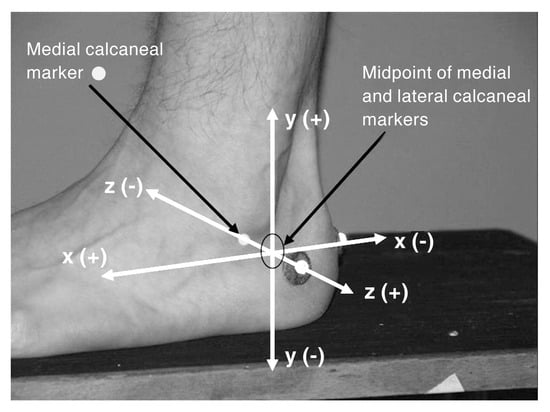
Figure 6.
Experimental markers mounted on the calcaneus are used to define the local coordinate system for the calcaneus and the reference frame for the midtarsal joint.
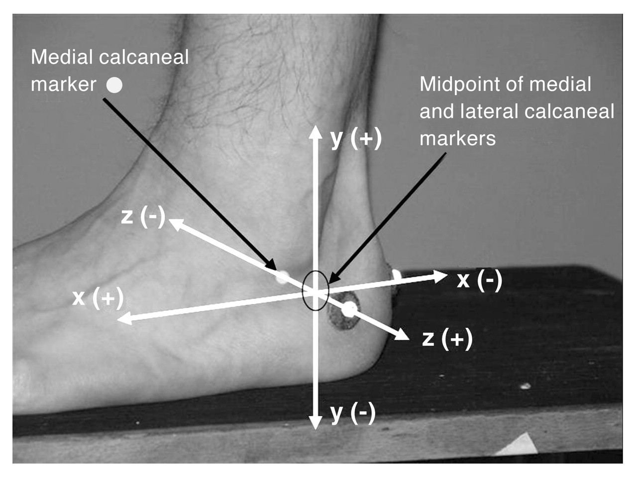
- The z-axis (medial/lateral) of the local coordinate system coincides with the medial and lateral markers.
- The x-axis (anterior/posterior) of the local coordinate system coincides with a line between the midpoint between the medial and lateral markers and the posterior-mounted calcaneal marker.
- The y-axis (vertical) is perpendicular to the x-and z-axes (and is therefore perpendicular to the supporting surface).
As methods of aligning external foot markers relative to the internal foot anatomy become available through the use of ultrasound or magnetic resonance imaging, for example, we would expect these definitions to be updated and that, in time, absolute measures of calcaneal position and motion will become possible.
Converting Clinical Models from Old to New Terms of Reference and Terminology
It is imperative that we demonstrate how the now redundant two-axis model of the midtarsal joint relates to the one-axis model and its new terms of reference and terminology. In doing this, we first discuss the reference system for the two-axis model. Traditional concepts of how the midtarsal joint functions to compensate for a forefoot valgus deformity suggest that it will invert by rotation around the “longitudinal axis.”[10] Where does the frontal plane in which this inversion motion takes place lie? It must be the frontal plane as defined in the reference system in which the longitudinal axis is defined. If the longitudinal axis is 9° from the sagittal plane and 15° from the transverse plane, where are these planes and how are they defined? These angles for the longitudinal axis relate to a reference system based on the longitudinal bisection of the foot and the supporting surface (as they appear in the article by Hicks[11]), and, therefore, so too does the frontal plane in which the compensation takes place. The sagittal and transverse planes that are referred to are also defined by this system.
The same is true for the “oblique axis.” In the case of an ankle equinus deformity, for example, one mechanism of compensation is said to be dorsiflexion around the oblique axis.[10] Where does the sagittal plane in which this dorsiflexion takes place lie? Again, it must be as defined by the reference system in which the oblique axis is defined. The rather nebulous referencing systems used to define the longitudinal and oblique axes can be interpreted from illustrations and seem to be based on the longitudinal axis of the foot and the supporting surface, not far removed from the reference system we are proposing. Therefore, we envisage few difficulties in making the transition from the reference system of the two-axis model to the system we are proposing in the one-axis midtarsal joint model.
If we refer to the sagittal, frontal, and transverse plane moments and motions of the midtarsal joint as occurring around the x-, y-, and z-axes as we have defined them, we will be using terms of reference and terminology that are common to clinical practice and research. We are not greatly changing our clinical model of function, but we are clarifying its scientific basis, enabling us to establish with clarity a link between clinical and experimental models of the joint.
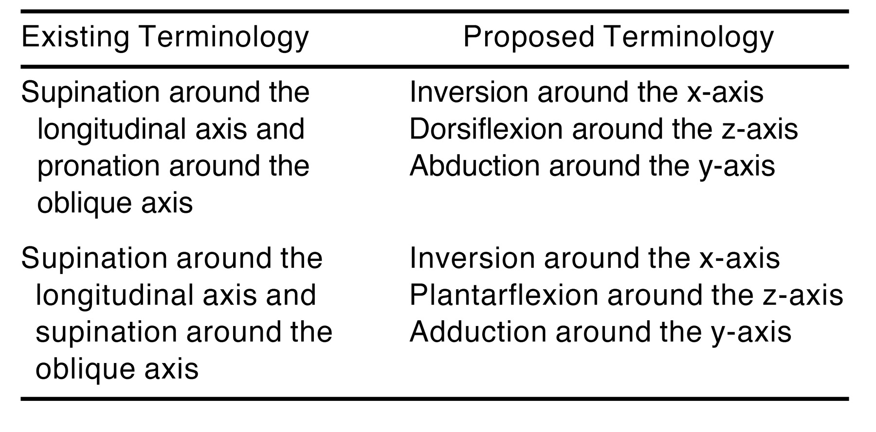
Understanding that this move to new terminology is not a gulf in our thinking enables us to more easily reinterpret texts that persist as the main basis for the application of biomechanical principles in podiatric medical practice. Table 1 illustrates how existing terminology can be reinterpreted using the proposed terminology. This reinterpretation is not complex, although the scientific rationale behind it may seem so. One feature of the interpretation of the two-axis model description using the proposed terminology is the realization that the midtarsal joint does not necessarily undergo supination (coupled inversion, plantarflexion, and adduction) or pronation (coupled eversion, dorsiflexion, and abduction) but that it can undergo different combinations of the three planar components (eg, inversion coupled with dorsiflexion and abduction). This concept agrees with data describing the navicular-cuboid motion relative to the calcaneus[1] and with related works.[11,12] This is a perfect example of how the proposed terms of reference and terminology align experimental and clinical models of midtarsal joint function.

Table 1.
Existing and Proposed Terminology for Movements at the Midtarsal Joint
Closing Remarks
The two-axis model of midtarsal joint function was developed by clinicians in an attempt to provide a biomechanical framework to explain what was observed clinically and because there was no means of quantifying the joint motion experimentally. As developments in biomechanics research have taken place, it should be recognized that the two-axis model creates a significant disparity between the clinical perspectives of joint function and the research (scientific) perspective. The aim of all biomechanics research, however far removed it may initially seem, is to generate new knowledge that can be applied with success in the clinical context. For this to occur, the terms of reference between the scientist and the clinician must be the same. If this is not the case, then clinicians will not benefit from advances in scientific biomechanical research. Likewise, experimental workers may fail to adequately address a clinical question. For example, how might we use emerging data[1,12–14] to enhance our understanding of the development of clinical pathology if the data relate to axes and motions that are different from those used in clinical models of biomechanically related pathology? Can we realistically continue to work with models based on pure theory when experimental results are available as an alternative? At some point, we must reassess the two-axis model in light of new evidence; that process has begun,[1–4] and it must continue. Our proposal is building on the debate thus far, which has centered on experimentally and clinically based approaches to the midtarsal joint. What we propose will facilitate the cohesion of these two interdependent schools of thought. The two-axis model might serve us well if we were to always have simple theoretical clinical models of joint function and dysfunction. However, as biomechanics research advances and we approach a more scientific basis for our understanding of joint function and dysfunction, we must ensure that we are all using the same appropriate biomechanical language if we wish to incorporate this research progress into clinical models of foot function. By adopting our suggested terms of reference and terminology, podiatric medical practice will take a step toward achieving this language uniformity.
The described terms of reference and terminology are not revolutionary. Their fundamental basis has existed since joint motion was described in terms of its cardinal body plane components. Neither are the terms of reference and terminology new to clinical and orthosis practice, since we already use the local reference system to describe the subtalar, ankle, and first metatarsophalangeal joints, although many podiatric physicians may not have fully understood the scientific rationale behind their use of the cardinal body planes as reference planes. It is a wonder, however, that it has taken us so long to adopt more standard terms of reference and terminology for the midtarsal joint. Adopting these standard terms of reference and terminology now will reflect our acceptance that biomechanics of the foot is a dynamic body of knowledge and will prepare us for more emerging scientific evidence that will inform our clinical practice.
Conclusion
We propose that the motion at the midtarsal joint be described using one axis of rotation for any instant in time and that descriptions of joint kinetics and kinematics relate to moments and motion in the cardinal body planes as defined by the x-, y-, and z-axes of the local reference system of the calcaneus.
Acknowledgments
Kevin Kirby, DPM, for his contribution to discussion regarding this work.
References
- Nester CJ, Findlow A, Bowker P: Scientific approach to the axis of rotation at the midtarsal joint. JAPMA 91: 68, 2001.
- Keenan AM: “Understanding Midtarsal Joint Function: Fact and Fallacy,” in Conference Book of Proceedings for the 17th Australian Podiatry Conference, ed by AM Keenan, HB Menz, p 107, Australian Podiatry Council, Melbourne, 1996.
- Payne CB: The role of theory in understanding the midtarsal joint. JAPMA 90: 377, 2000.
- Sims DS, Cavanagh PR: “Selected Foot Mechanics Related to the Prescription of Foot Orthoses,” in Disorders of the Foot and Ankle: Medical and Surgical Management, Vol 1, ed by MH Jahss, p 469, WB Saunders, Philadelphia, 1991.
- Van Langelaan EJ: A kinematical analysis of the tarsal joints: an X-ray photogrammetric study. Acta Orthop Scand Suppl 204: 1, 1983.
- Benink RJ: The constraint-mechanism of the human tarsus: a roentgenological experimental study. Acta Orthop Scand Suppl 215: 1, 1985.
- Wu G, Siegler S, Allard P, et al: ISB recommendation on definitions of joint coordinate system of various joints for the reporting of human joint motion: part I. Ankle, hip, and spine. J Biomech 35: 543, 2002.
- Lundberg A: Kinematics of the ankle and foot: in vivo roentgen stereophotogrammetry. Acta Orthop Scand Suppl 233: 1, 1989.
- Wu G, Cavanagh PR: ISB recommendations for standardization in the reporting of kinematic data. J Biomech 28: 1257, 1995.
- Valmassy RL: “Pathomechanics of Lower Extremity Function,” in Clinical Biomechanics of the Lower Extremity, ed by RL Valmassy, p 65, CV Mosby, St Louis, 1997.
- Hicks JH: The mechanics of the foot. J Anat 87: 345, 1953.
- Hunt AE, Smith RM, Torode M: Extrinsic muscle activity, foot motion and ankle joint moments during the stance phase of walking. Foot Ankle Int 22: 31, 2001.
- Rattanaprasert U, Smith R, Sullivan M, et al: Three-dimensional kinematics of the forefoot, rearfoot, and leg without the function of tibialis posterior in comparison with normals during stance phase of walking. Clin Biomech (Bristol, Avon) 14: 14, 1999.
- Kidder SM, Abuzzahab FS Jr, Harris GF, et al: A system for the analysis of foot and ankle kinematics during gait. IEEE Trans Rehabil Eng 4: 25, 1996.
© 2006 American Podiatric Medical Association