


Abstract
Resonant-vibration de-icing offers a low-power alternative to electrothermal systems, but its effectiveness depends on ice fracture and ice–substrate interfacial failure under dynamic loading. This study develops a coupled experimental–numerical methodology to characterize ice fracture and interfacial delamination and assess ice-phobic coatings for vibration-based de-icing. A 1 mm thick 2024-T3 aluminum plate (50 × 130 mm) was suspended under free–free conditions and excited using a bonded piezoelectric actuator. Approximately 5 mm thick mold-ice layers were tested on bare aluminum and two coated substrates. Resonant modes were identified through low-amplitude frequency sweeps, followed by progressively increased excitation until cracking and complete delamination occurred. Plate acceleration and high-speed imaging characterized vibration response, crack initiation, and propagation, while an ABAQUS piezoelectric finite-element model determined stress fields and fracture metrics. Ice cracking occurred first at tensile stresses of 1.6–2.1 MPa, with fracture toughness values below 0.34 MPa√m, starting from the top of the ice layer where solicitation was maximum, all the way to the interface at the bottom of the ice layer. For bare aluminum, interfacial fracture followed the fracture of the ice layer, with toughness ranging from 0.25 to 0.36 MPa√m. An oven-cured silicone–acrylic coating reduced the required delamination power by approximately fourfold and lowered interface toughness to 0.16 MPa√m, although performance depended on curing and mechanical durability. A commercial coating was also tested, providing signification power reduction for the first two test repetitions, but no longer worked for subsequent testing due to its poor durability and mechanical performances. The framework enables evaluation of ice fracture, interfacial behavior, and coating durability under resonant excitation.
1. Introduction
Icing is a widespread phenomenon in regions exposed to subfreezing conditions [1]. Its development is controlled by several factors, including temperature, relative humidity, pressure, wind velocity, air density, altitude, and various microphysical processes [2,3]. Icing poses major challenges across multiple sectors by affecting both man-made structures and transportation systems [4,5,6,7,8]. In aviation, ice accumulation on aircraft surfaces constitutes a critical safety risk because it alters aerodynamic performance and increases structural loads, leading to severe loss of lift and potential flight instability. At the same time, the additional drag caused by ice accumulation leads to further aerodynamic penalties, degraded handling characteristics, and higher fuel consumption [9]. The situation is particularly critical for helicopters, where ice accretion not only reduces lift and increases drag but also introduces torque fluctuations, vibrations, and rotor imbalance, all of which can compromise flight stability [10].
Consequently, dedicated ice-protection systems are essential to maintain safe and efficient operation. Icing mitigation relies on two overarching strategies, anti-icing and de-icing. Anti-icing seeks to prevent ice from accreting on the surface, whereas de-icing removes ice after it has formed. Each strategy comprises passive and active methods: passive approaches exploit the structure’s intrinsic surface properties to hinder or shed ice, while active approaches employ externally powered systems, such as thermal, chemical, or pneumatic means [11,12]. For wind turbines and aircraft, the predominant solutions are thermal methods that warm exposed surfaces. These include hot-air anti-icing or embedded electric heaters. Their primary limitation is the high power consumption needed to maintain protection [4]. Mechanical de-icing requires comparatively little energy. It induces large stresses within the ice, causing fracture and promoting shedding. These methods are mainly intended for de-icing, but with proper control they can also function as anti-icing [13]. Many aerospace strategies can be adapted to wind energy, provided parameters such as wind speed, chord length, and airfoil geometry are appropriately scaled [14].
A well-established mechanical aviation solution is the pneumatic boot: inflatable membranes along the leading edge that cyclically pressurize and relax to crack and eject ice. These systems are valued for simple operation, quick response, and modest power demand [15]. Limitations include difficult installation and high maintenance driven by the limited durability of the boots [16]. Electro-impulsive or expulsive de-icing is another mechanical option that places a spiral coil near the inner face of a metallic skin. Very short, electromagnetically induced vibration pulses flex the metal abrasion shield and fracture the ice. When current is applied to the coil, the resulting magnetic field across the profile thickness deforms the metal, producing rapid surface motion that expels the accumulated ice. The system is efficient, environmentally friendly, and low in energy demand, does not interfere with radio transmission, and can be automated easily [14]. However, its practical use has remained limited because the strong electromagnetic pulses can cause structural fatigue in metallic skins and face challenges when being adapted to composite skins or large wind-turbine blades, for which fatigue performance and applicability are still unverified [17].
To reduce power demand, alternative mechanical concepts have been investigated. In recent years, vibratory and ultrasonic de-icing systems have gained attention for their potential weight and energy savings. The concept of ultrasonic de-icing was originally introduced by Ramanathan [18]. In his work, Ramanathan employed resonant piezoelectric elements to launch ultrasonic surface waves that produced interfacial shear at the ice–substrate boundary. These pioneering experiments laid the groundwork for subsequent piezoelectric and ultrasonic de-icing technologies. Yin et al. [19] conducted experimental studies on ultrasonic de-icing using PZT actuators for wind-turbine blades. They outlined a bonding method for mounting ultrasonic transducers on the composite skin and analyzed the composite plate–ice laminate with harmonic finite-element modeling. Both the harmonic analysis and feasibility tests indicate a clear advantage for ultrasonic de-icing. Moreover, the observed de-icing time was much shorter than the freezing time, implying that continuous operation under icing conditions can prevent accretion. Ultrasonic de-icing has been explored for wind-turbine blades, high-voltage transmission lines, and aircraft. These approaches can be particularly advantageous for configurations with limited available power where thermal protection is impractical [13]. This method exploits the shear strength of the ice–substrate bond. Ice is removed by a combination of cavitation, local heating, and, above all, the mechanical action produced by ultrasonic vibration. When high-energy ultrasonic waves traverse a plate–ice bilayer, the mismatch in acoustic properties leads to different wave speeds in the two media and generates shear stresses at the interface. These stresses initiate cracking and promote debonding of the ice layer [18]. Laboratory studies have shown that ice up to 2.5 mm thick can be removed at temperatures near −20 °C with power densities as low as 0.7 kW/m2, reducing energy demand by more than 80% relative to electrothermal systems [20]. However, despite its promising efficiency, ultrasonic de-icing still faces several practical limitations, such as the need for precise impedance matching and frequency tuning to achieve resonance, potential actuator fatigue or delamination under prolonged excitation [17].
Among electromechanical vibratory de-icing approaches, piezoelectric actuator systems have been investigated the most. These devices generate localized shear at ice accretion sites, weakening the interface so that normal impulsive loading can remove the layer. Villeneuve et al. [21] induced cracking and debonding in a large plate covered by a narrow ice strip that mimics leading edge accretion. Numerical simulations identified low-frequency resonant modes capable of initiating ice cracking and delamination, and experiments confirmed these predictions. The excitation creates localized deformation and interfacial stress fields that, when sufficiently high, release the accumulated ice. This resonance-driven strategy shows strong potential to reduce de-icing power requirements while maintaining effective ice removal. Beyond experimental demonstrations, extensive efforts have focused on numerically modeling piezoelectric de-icing systems. These models simulate the coupled electromechanical behavior of actuators, estimate vibration-induced stresses at the ice–substrate interface, and quantify how transducer placement, drive frequency, and ice layer properties govern de-icing efficiency [22]. Harvey and, later, Villeneuve et al. [21,23,24] delivered proof-of-concept results for vibration-based de-icing by driving piezoelectric patch actuators at the host structure’s resonant frequencies. They achieved full or partial ice removal on multiple configurations—including a flat aluminum plate, a thinned Bell 206 main-rotor blade, and Bell 206 tail-rotor sections—using numerical simulations to predict resonant frequencies and mode shapes and thereby optimize actuator placement and excitation for maximum effectiveness. However, the studies only considered stresses and did not use fracture mechanics to investigate cracking and delamination, which is a required next step in the understanding of shedding phenomena. Palacios [25,26] created a three-dimensional finite element framework to guide the design of piezoelectric de-icing experiments. The model captured the coupled electromechanical response of actuator–structure assemblies and was used to optimize drive strategies. A key outcome was the detailed analysis of impedance matching between the piezoelectric patches and the host structure, which proved essential for efficient vibration transfer. Insights from this simulation directly shaped the experimental layouts and helped achieve effective ice removal under laboratory conditions. Pommier-Budinger et al. [27] introduced a computational approach to estimate the voltages and currents required in a piezoelectric de-icing system to trigger either cohesive fractures within the ice or adhesive failure at the ice–substrate interface. Combining beam theory, modal analysis, and numerical tools, they delivered an initial framework whose outputs were fed into the design stage to select suitable vibrational modes. They further showed that pairing the actuators with an ice-phobic coating can both lower the power demand and prolong actuator service life [28]. These findings highlight the critical role of ice–substrate adhesion in the efficiency of vibration-based de-icing systems.
Research into the adhesion of ice has a long history, largely driven by de-icing needs [29]. Studies have examined refrigerated ice bonded to metals (stainless steel) and non-metals (polystyrene, polymethyl methacrylate), evaluating how cross-sectional area, ice thickness, and ice–substrate temperature affect adhesion [30]. The principal findings are: (1) for metal and non-metal substrates alike, adhesive strength in shear and in tension does not depend on cross-sectional area or thickness, but increases approximately linearly as temperature decreases down to −15 °C; (2) tensile adhesive strength is roughly one order of magnitude larger than shear strength on both classes of substrates; (3) theoretical adhesion strengths predicted by classical and quantum bonding models are several orders of magnitude higher than experimentally measured values, highlighting the dominant role of defects, interfacial roughness, and imperfect bonding conditions in real ice–substrate interfaces [30]. Ice-phobic coatings have therefore gained attention as passive anti-icing solutions intended to delay accretion or promote detachment from solid surfaces, with performance commonly assessed by icing delay time and interfacial adhesion strength. However, in harsh environments that combine low temperatures with high humidity, such passive surfaces frequently lose effectiveness, leading to slower shedding and comparatively strong adhesion on coated blades [31]. In contrast, active approaches such as electrothermal systems are effective but require substantial power during continuous use. Because no single technique meets all operational needs, hybrid ice-protection concepts have emerged. Relative to stand-alone solutions, hybrids yield longer freezing times, reduced interfacial adhesion, higher de-icing efficiency, and markedly lower energy demand [32,33]. These pair passive ice-phobic coatings (which lengthen freezing delay and lower adhesion) with active de-icing to enable efficient removal. An ice-phobic topcoat lowers the adhesion between ice and the rotor surface, thereby reducing the mechanical energy needed for removal; experiments indicate that, relative to a bare electrothermal system, adding such a coating can cut interfacial ice adhesion strength by more than 50% [34]. This reduction in adhesion directly translates into lower power consumption for the active system, demonstrating the clear efficiency benefits of hybrid approaches. Samad et al. [35] tested a superhydrophobic–electrothermal hybrid across multiple icing regimes. The hybrid configuration markedly reduced heater power: under glaze ice, from 18.4 W to 11.2 W, and under rime ice, from 93.15 W to 56.7 W. In total, the rotor-integrated superhydrophobic electrothermal system delivered effective protection with up to a 39% decrease in energy use relative to the same heating setup on a hydrophilic surface. Overall, the rotor-integrated superhydrophobic electrothermal system achieved effective ice protection with up to 39% lower energy consumption compared to an identical heating configuration applied to a hydrophilic surface. None of those studies explored fracture mechanics, as is done in this preliminary investigation.
Although several studies have investigated ultrasonic and piezoelectric de-icing using localized or surface-wave actuation, only a limited number of works have examined purely mechanical vibration systems operating at the structural resonance of suspended plates. Most previous research has focused on high-frequency ultrasonic excitation rather than low-frequency mechanical modes. Therefore, there remains a lack of systematic experimental data on ice fracture and interfacial delamination driven by global plate vibrations, particularly for configurations representative of wind-turbine blades or aircraft skins.
The present study aims to address this gap. This preliminary study investigates ice fracture and ice/substrate interfacial delamination under dynamic excitation using a simple suspended flat plate setup harmonically excited. Experimental tests were performed using mold ice on a bare aluminum substrate and on two different surface coatings. Resonant vibration of the plates was monitored using an accelerometer, and the fracture and delamination process of the ice layer during each test was captured with a high-speed camera. A numerical model was also implemented in order to establish the stress levels involved during the different cracking and fracture obtained during the vibration tests. It was then possible to obtain different properties for the cohesive break within the ice layer as well as at the ice/substrate interface. It was also possible to obtain the performances of different ice-phobic coatings under this type of excitation. These results are particularly useful to better understand and design vibration-based de-icing systems and better characterize ice properties under dynamic excitation. This preliminary study has allowed us to confirm the proof-of-concept of the methodology and test setup developed for this purpose and to conclude on how to improve it for a future more comprehensive investigation.
2. Materials and Methods
To facilitate the fundamental understanding of the mechanics of ice fracture and to obtain material properties such as the cohesive and adhesive strength and facture toughness, a very simple structure was selected for this preliminary proof-of-concept study. A small thin rectangular flat plate was designed for its symmetry, regular geometry, ease of fabrication, its simple stress distributions and because some results are available from a previous project [36,37]. It is also easier to generate an ice layer of regular shape for this geometry using molds or sprinkler ramps. A numerical model of the setup was also developed to calculate the stresses and toughness involved during the dynamic excitation.
2.1. Flat Plate Experimental Setup
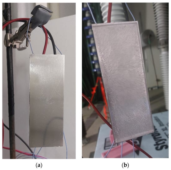
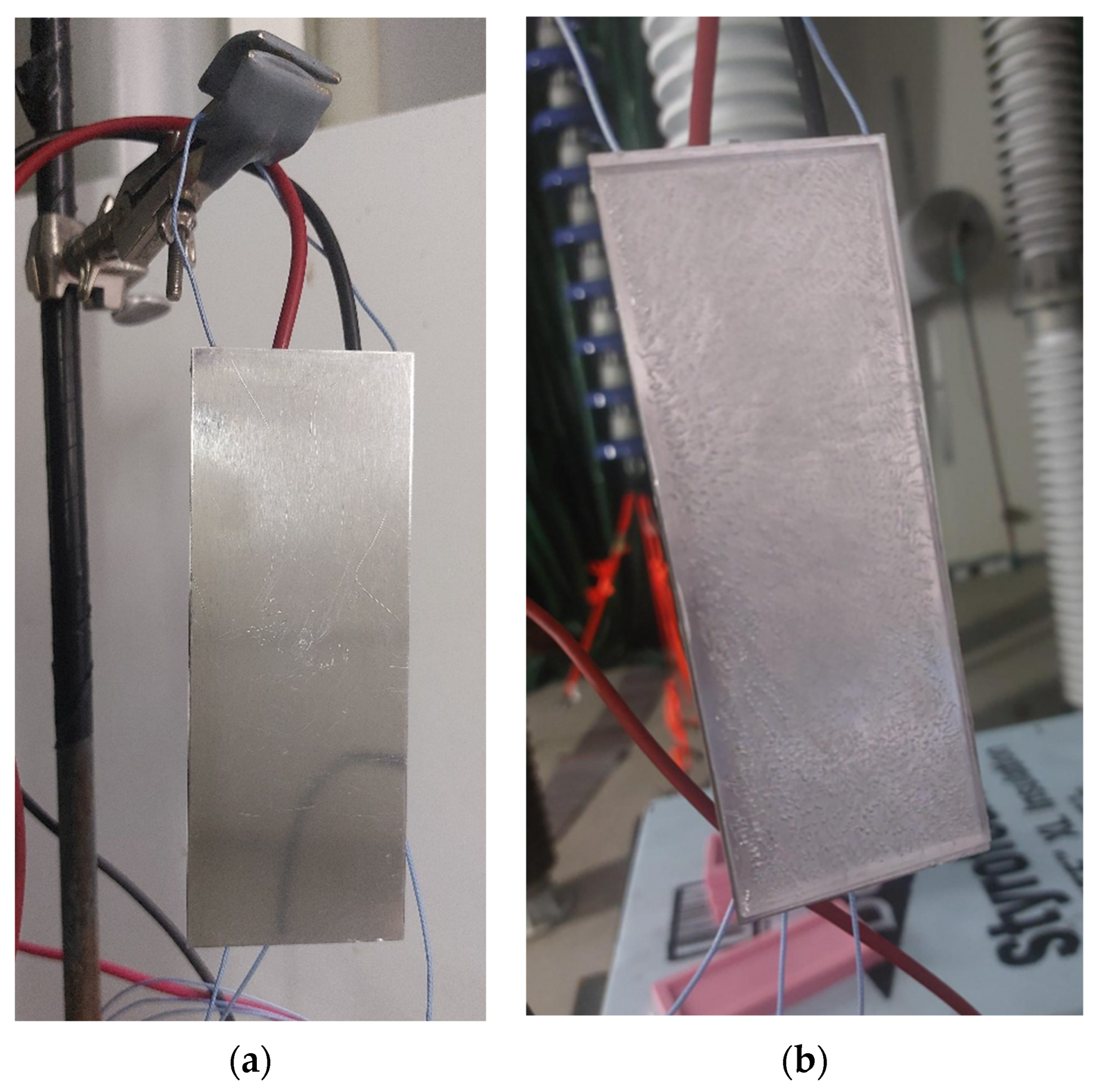
The flat plate setup consists of a rectangular 1 mm thick aluminum 2024-T3 flat plate of 50 mm × 130 mm. The plate is installed in a free condition for all its sides (no fixed support) using a small string glued to two of its corners. This allows the plate to be freely suspended in the air, as shown in Figure 1. One plate is fabricated for each surface tested. A P-876.A15 actuator patch, manufactured by Physik Instrumente (PI) SE & Co. KG (Karlsruhe, Germany), was bonded at the center of the back surface of the plateThe patch is 61 mm in length, 35 mm in width, and has a total thickness of 0.8 mm. The actuator was bonded to the surface using the same procedure employed for installing strain gauges, with Epo-Tek 353ND adhesive (Epoxy Technology, Inc., Billerica, MA, USA), as recommended by the piezoelectric actuator manufacturer. To excite the piezoelectric actuator, an Agilent 33500B waveform generator (Agilent Technologies, Santa Clara, CA, USA) was used, and the signal was amplified using an AL-1000-HF-A amplifier (Amp-Line Corp., West Nyack, NY, USA). The apparent electrical power supplied to the actuator can be calculated using the following equation, as given by the manufacturer:
with Pm being the average apparent electrical power, C the actuator electrical capacitance, f the frequency of excitation and Uh the voltage swing in Vpp. The electrical capacitance of the actuators was 45 nF. An PCB Piezotronics model 352C22 accelerometer is installed at the center of the back of the plate to measure vibration level and is connected to a high sampling rate acquisition card inside a computer with homemade software for data acquisition.
Figure 1.
(a) Flat plate experimental setup and (b) mold-ice layer accumulation.
For this preliminary study, only mold ice was investigated as a starting point to develop and validate the methodology, since it is easier and quicker to generate the samples. The method will be expanded to atmospheric icing in future studies using the proven method. A 5 mm thick rectangular block ice layer sample is prepared on the whole plate before each test. To generate the ice layer, deionized water is used to fill a silicon mold. Then, the plate is put on top of the water and let to rest in the cold room at −15 °C for a few hours until the water has completely frozen (Figure 1). In addition to the accelerometers, a high-speed camera is used to obtain additional information on the behavior of ice failures and the propagation process on the plate. The camera is set to 80,000 fps. Finally, a thermal camera was also used and confirmed that there was no significant temperature increase during the test and that ice failures were only due to mechanical solicitations.
2.2. Surface Coatings
In order to investigate the combined contribution of active vibration-based de-icing and passive surface modification in reducing energy consumption, interfacial properties, and delamination behavior, two distinct coatings with different levels of ice-phobicity and commercial availability were selected. The first coating (Coating 1) was developed in-house by the research group. This formulation was based on a silicone–acrylic resin matrix, modified with functional additives including crosslinking agents for improved mechanical stability, UV absorbers to resist photodegradation, and silica–graphene oxide nanoparticles to enhance surface roughness and hydrophobicity. This custom-designed hybrid coating represented an advanced material concept aimed at combining long-term durability with superior ice-phobic performance and was specifically tailored for potential applications in wind energy and aerospace sectors. The second coating (Coating 2) was a commercial two-component spray system designed to produce a superhydrophobic surface finish. The system was selected for its widespread availability and its established ability to create micro/nanostructured roughness that enhances water repellency. Unlike other products, which rely only on intrinsic hydrophobic chemistry, this coating incorporates topographical features to reduce liquid adhesion and delay ice formation.
Prior to coating application, the aluminum substrates were carefully degreased with ethanol and subsequently air-dried at room temperature to ensure clean and uniform surfaces. The application process for each coating was carried out under controlled laboratory conditions. The in-house silicone–acrylic hybrid formulation was prepared and applied using a film applicator to achieve a uniform wet-film thickness of 500 μm. Care was taken to ensure uniformity of the film across the aluminum substrates. After application, the samples were left under ambient conditions to ensure complete crosslinking and stable mechanical properties. For the commercial system, the application was performed in two stages according to the manufacturer’s guidelines. First, a resin-based base layer was uniformly sprayed onto the aluminum substrates. The wet-film thickness was continuously monitored with a wet-film gauge to maintain it at approximately 500 μm. Once this base layer had partially dried, a powder-based topcoat was applied to create a hierarchical superhydrophobic surface texture. This two-step process ensured the formation of a robust surface morphology essential for repelling water droplets and delaying ice nucleation.
The curing procedure was tailored for each coating system. The in-house silicone–acrylic hybrid coating was cured in a convection oven at 160 °C for 20 min, which resulted in full crosslinking. Following the results obtained (presented in the Results section), another curing method was used to improve the flexibility and reduce the brittle nature of the product. A slower method was used in which the silicone–acrylic hybrid coating was allowed to cure at room temperature for seven days under ambient laboratory conditions until complete hardening and stabilization of the films were observed. This slower curing process promoted a more gradual crosslinking reaction, allowing better polymer chain mobility and relaxation, which reduced internal stresses and yielded a tougher, more mechanically resistant coating. The commercial coating system was cured according to the manufacturer’s recommendations, which specified drying intervals between the base and top layers to ensure optimal adhesion and surface performance. By adopting uniform film thicknesses of 500 μm and controlling the application process carefully, a fair evaluation of their ice-phobic and energy-saving performances in combination with the vibration-based de-icing system was possible. This methodological consistency ensured that the observed differences in de-icing efficiency could be directly attributed to the intrinsic properties of the coatings rather than to variations in film thickness or application procedures.
Basic properties of each surface were measured and are presented in Table 1. The wettability of the substrates was evaluated by static water contact angle measurements. The adhesion reduction factor is obtained by measuring the shear stress required to detach an iced coupon from the substrate under a centrifugal acceleration. Then that value is compared with the value obtained for bare aluminum to determine the reduction factor. The bare aluminum substrate exhibited a moderate hydrophilicity, with a contact angle of 86°, and an adhesion reduction factor of 1, since it serves as the reference surface. Coating 1 showed a higher contact angle of 105°, indicating the transition to a hydrophobic regime and a 15.6-fold reduction in ice adhesion compared to aluminum. Coating 2, characterized by a superhydrophobic contact angle of 160°, demonstrated an outstanding decrease in ice adhesion, up to two orders of magnitude compared to bare aluminum, below the sensitivity of the measuring apparatus. The strong correlation between the increase in water contact angle and the adhesion reduction factor confirms that enhanced hydrophobicity effectively lowers the interfacial ice–substrate bonding strength, leading to improved ice-phobic behavior. This improvement arises from the combined effects of reduced real contact area, trapped air pockets at the interface, and diminished capillary forces, which collectively minimize ice anchoring on the coated surfaces.
Table 1.
Surface base properties.
2.3. Numerical Model of the Flat Plate
A numerical model of the setup was created with ABAQUS CAE 2025 software because it handles piezoelectric-type finite elements, and to build on the work performed in previous studies [21,23,24,38]. A 0.05 m × 0.13 m and 0.001 m thick rectangular plate was modeled made of aluminum with a mass density of 2780 kg/m3, a Young’s modulus of 73.1 GPa, and a Poisson’s ratio of 0.33. No boundary condition was imposed on the plate as it was in a free condition. Linear S4R shell elements were used to mesh the plate.
The P-876.A15 actuator was modeled using a 3D extruded deformable solid with its corresponding dimension. The PIC255 material was modeled using its stiffness, electrical permittivity, and the piezoelectric coefficient properties provided by the manufacturer, as detailed in [23]. The patch is tied to the flat plate using a tie constraint and positioned at the center of the plate, corresponding to its position on the experimental setup. C3D8E 8-node piezoelectric brick elements were used to mesh the actuator, allowing coupling between electrical and mechanical properties with electrical potential and displacement degrees of freedom. To obtain vibration, electrical boundary conditions are applied on the faces of the actuator.
The Ice layer was also added in the numerical model on the top surface of the flat plate. The layer covered the whole surface (50 mm × 130 mm) and was modeled as a solid homogenous 3D deformable extruded part. The part was connected to the plate with a Tie constraint. The properties of the ice layer in the numerical model were defined from a previous study [36]. The ice volume was meshed with C3D8R 8-node linear brick elements.
Two different simulations were performed on the modeled structure. A frequency analysis was first used to determine the resonant modes of the structure along with their corresponding mode shapes. Then the direct steady-state dynamic analysis was used to obtain the structure’s vibration amplitude response to different voltage excitation of the actuator. With this second analysis, the vibration levels are matched with the ones obtained experimentally, as measured by the accelerometer, and the different stresses in the Ice layer can be calculated. A convergence study was performed to ensure that the numerical implementation accurately simulates the dynamic behavior of the plate.
2.4. Experimental Protocol
The objective of this test campaign is to validate the methodology in order to be able to understand fractures and shedding behavior and to determine stresses, toughness and power level required to fracture and detach the ice layer under dynamic cyclic excitation. The first step for each test performed is to locate the resonant frequency of the mode tested. By performing frequency sweeps at very low voltage, the frequency of interest is identified without compromising the ice layer. Then, excitations of the actuator are performed over a short frequency interval around the mode of interest. For each frequency sweep, the voltage is slightly increased until a fracture is detected. The voltage is then identified and linked to the cohesive break in the ice layer, and acceleration is recorded by the accelerometers. A new scan is then performed at a very low voltage once again to determine the new frequency of the resonant mode of the plate due to modification of the rigidity and mass distribution of the plate. The method is then continued until cracking is complete and then for the progressive delamination of the ice from the plate until the ice layer is completely shed and falls from the plate. The high-speed camera is used throughout the test to capture the fracture and delamination process, and the thermal camera is also used to confirm that no significant heating is observed, and the process is completely mechanical. After testing, the numerical model is used to calculate the stresses and toughness for each ice break, and the voltage level is used to calculate the power consumption of the system. The process is performed for the bare aluminum plate as well as for the coated plates.
3. Results
3.1. Resonant Modes Analysis
The frequency analysis was run from 0 to 10,000 Hz, since the first resonant modes want to be used for the delamination of the ice for their high stress generation and lower power consumption [21]. The modal shapes obtained were first evaluated to establish the modes that are most susceptible to be excited by the setup configuration. Conclusions obtained from a previous study [23] have shown that the piezoelectric actuator must respect size and position of the anti-nodes to properly excite a resonant mode. A mode properly excited leads to higher vibration and consequently higher stress generation, which is more susceptible to generate ice delamination [24].
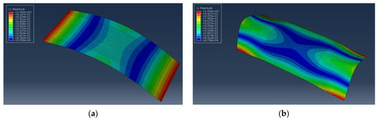
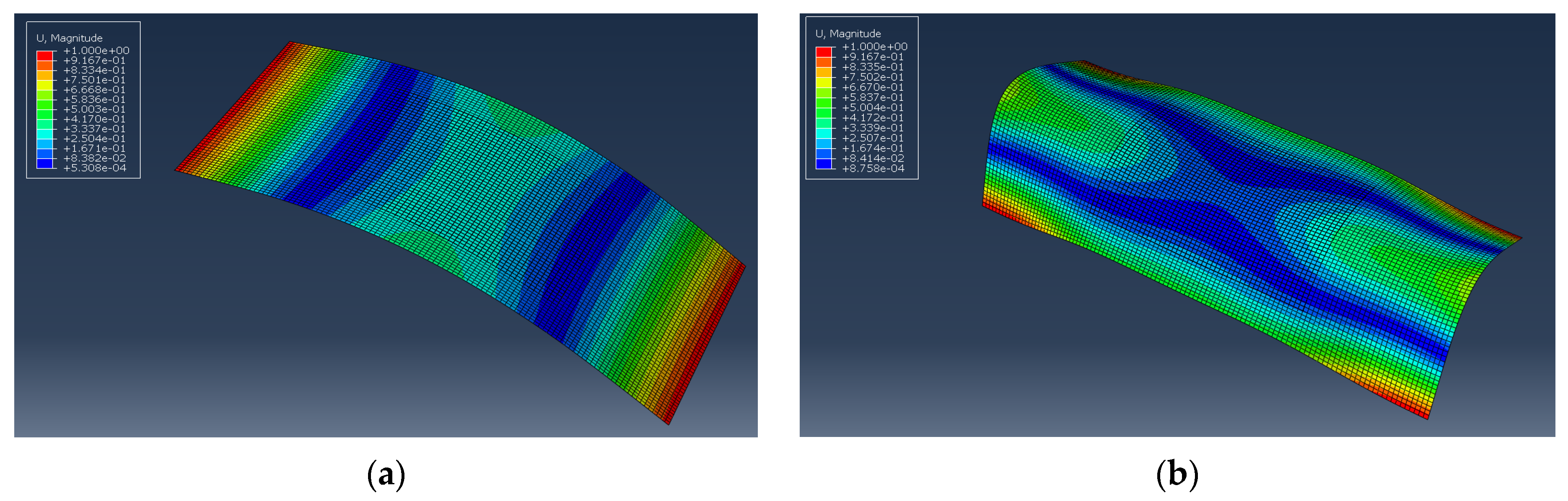
Sweep tests were performed from 0 to 10,000 Hz to excite the first resonant modes of the structures and validate the frequency analysis. The first and third modes were selected for this study (Figure 2). Mode 1 is a flexural mode, which consists of a single bending along the entire longitudinal direction of the plate. This high flexion is ideal to obtain cohesive break through the ice layer and generate progressive delamination, as shown in a previous study [37]. The second mode of interest is Mode 3, which is also a flexural mode, consisting of a single bending, but in the transversal direction. The flexion should again favor a cohesive break through the ice, but in the longitudinal direction, generating progressive fractures to better understand crack propagation in the ice layer.
Figure 2.
Numerical result for the mode shape of (a) Mode 1 and (b) Mode 3.
3.2. Cohesive Strength
Two modes of interest were selected to study the stresses and toughness required to obtained cracking and a cohesive break in the ice material. Flexural modes were selected to generate high solicitation in the ice layer, allowing fracturing of the ice layer in both directions, ideal for crack propagation study. During each test, the acceleration measured by the accelerometer was recorded and linked with the numerical model to obtain stress levels. In addition, the voltage and power necessary to obtain breaking of the ice layer under dynamic resonant excitation was also determined.
3.2.1. Aluminum Substrate—Mode 1
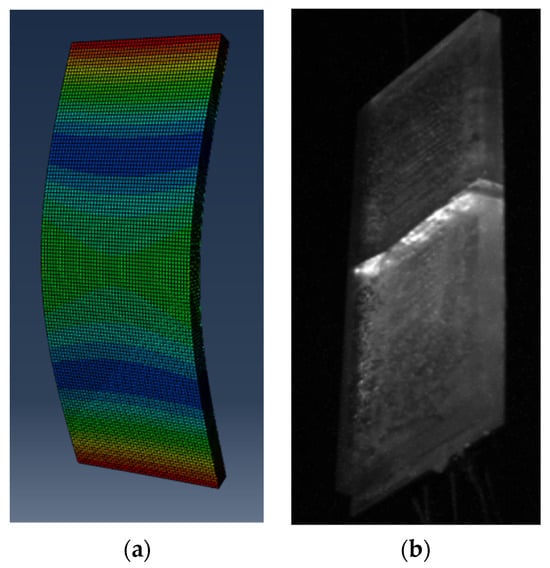
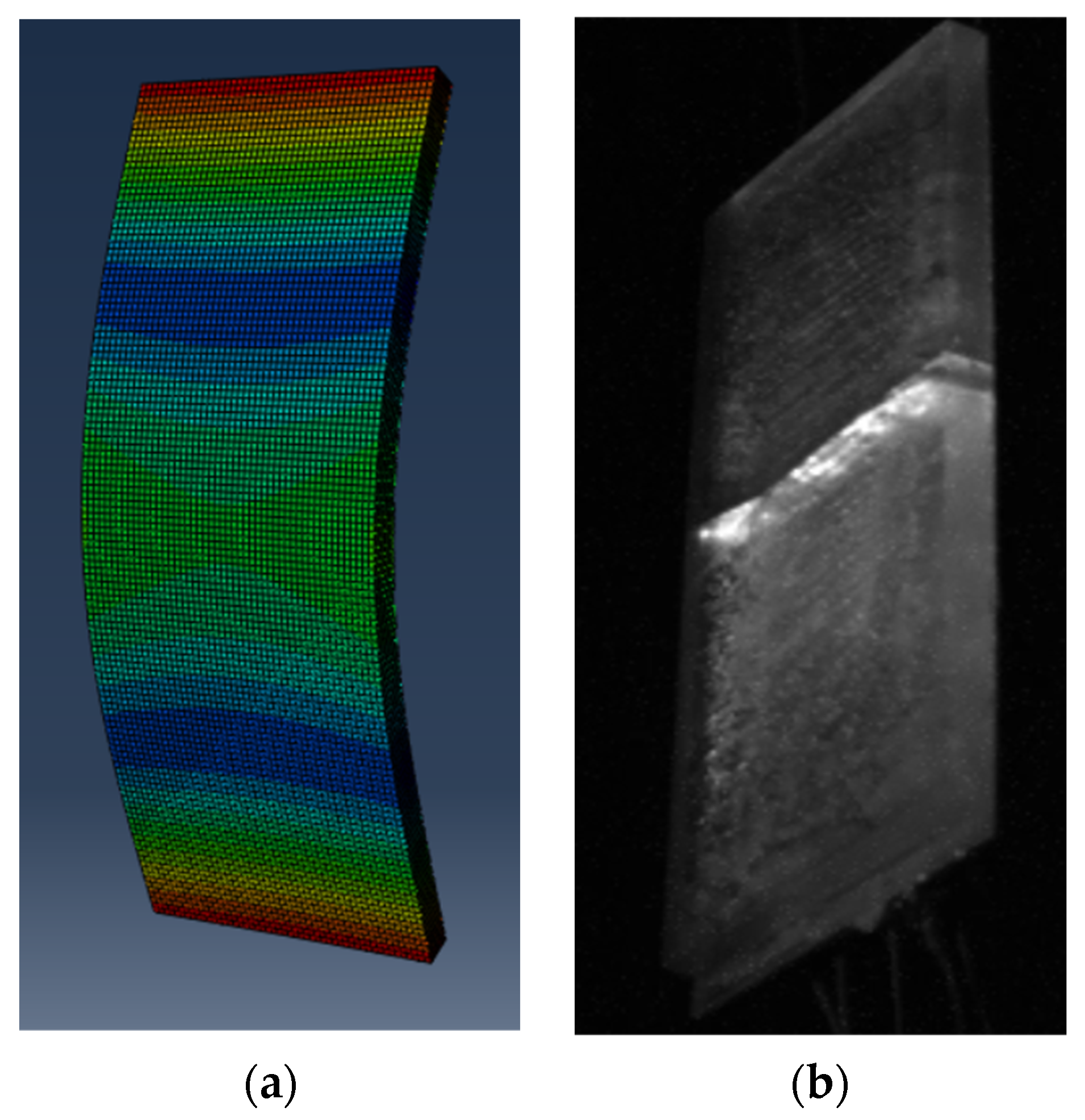
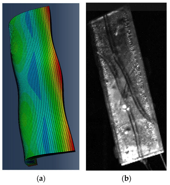
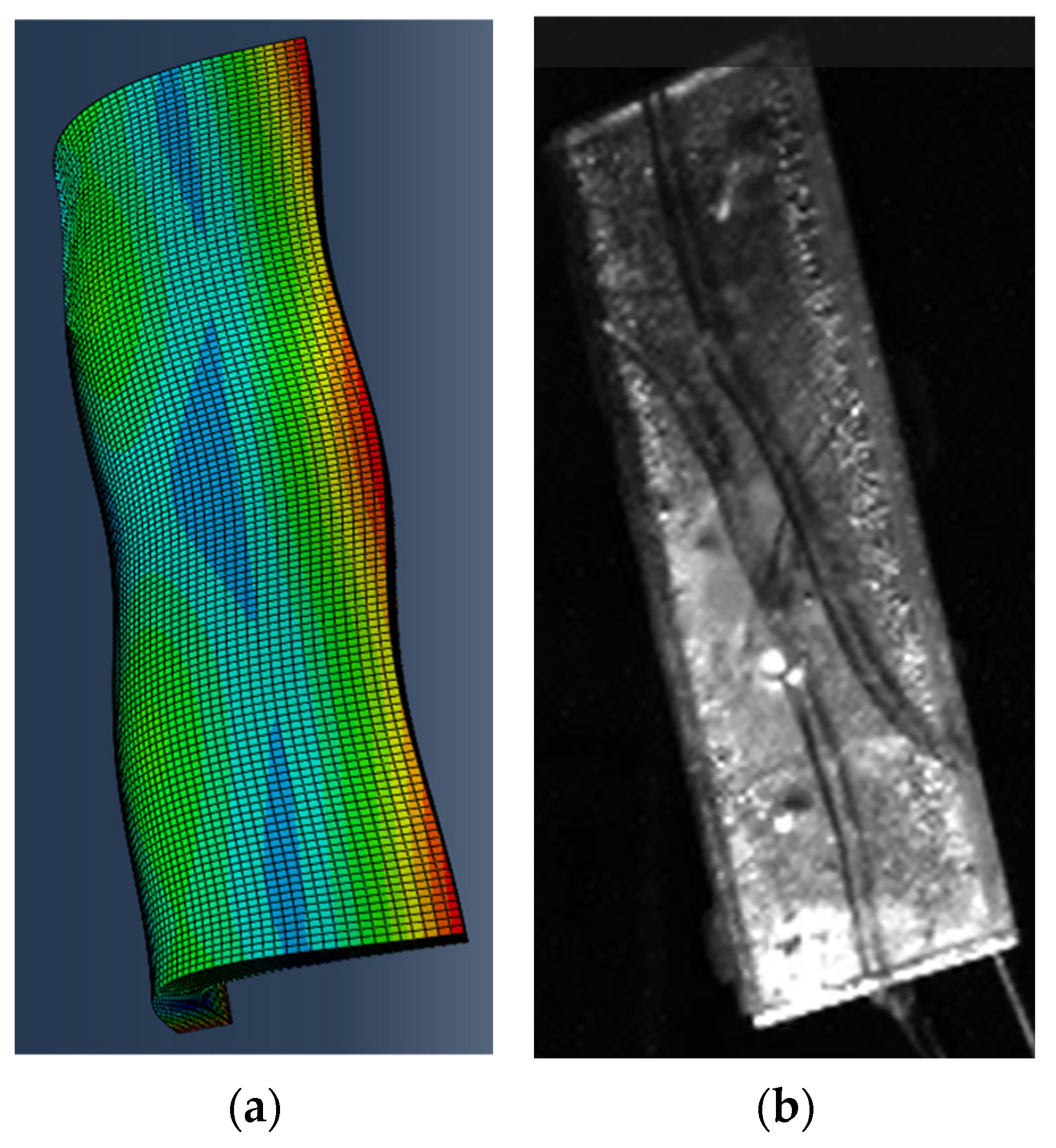
As detailed previously, the first mode of the structure is a flexural mode, which corresponds to a simple bending along the longitudinal direction of the plate. For each test, the exact frequency of the mode was first located, and then narrow frequency sweeps were performed around the mode to perform dynamic excitation of the ice layer. Voltage was slightly increased between each sweep until the cohesive break was obtained. Five test repetitions were performed on the aluminum plate. In each test, a crack consistently appeared at the center of the plate, precisely where the modal shape reaches its maximum amplitude. This location coincides with the area of highest mechanical tensile stress generated under Mode 1 bending. Figure 3 illustrates the alignment between the mode shape and the actual fracture location in the ice layer.
Figure 3.
Modal shape (a) and fracture in the center of the ice (b).
Table 2 highlights the failure thresholds observed across the different test repetitions under Mode 1 excitation. The frequencies obtained for Mode 1 were consistent for each test repetition, showing a good repeatability in the ice layer generated between each test. Acceleration values were recorded by the accelerometer mounted at the middle of the plate. The numerical model was then used to calculate the stress values associated with the tensile strength of mold ice for the corresponding vibration levels. The stresses obtained, between 1.6 and 2.1 MPa with an average value of 1.8 ± 0.2 MPa, are consistent with the findings of Palanque et al. [37], who also reported cohesive failure of ice near 2.0 MPa for mold ice under dynamic excitation. The experimental values obtained in this study fall within the same expected range. The power obtained to crack the ice was around 0.15 W.
Table 2.
Resonant Mode 1 cracking results for the aluminum substrate.
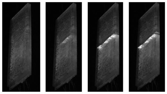
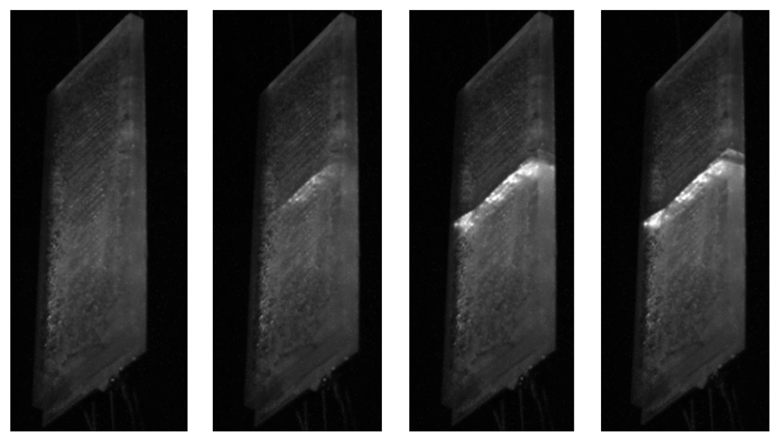
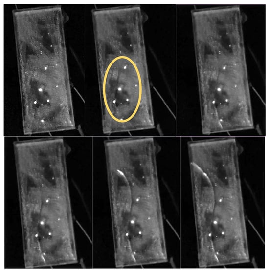
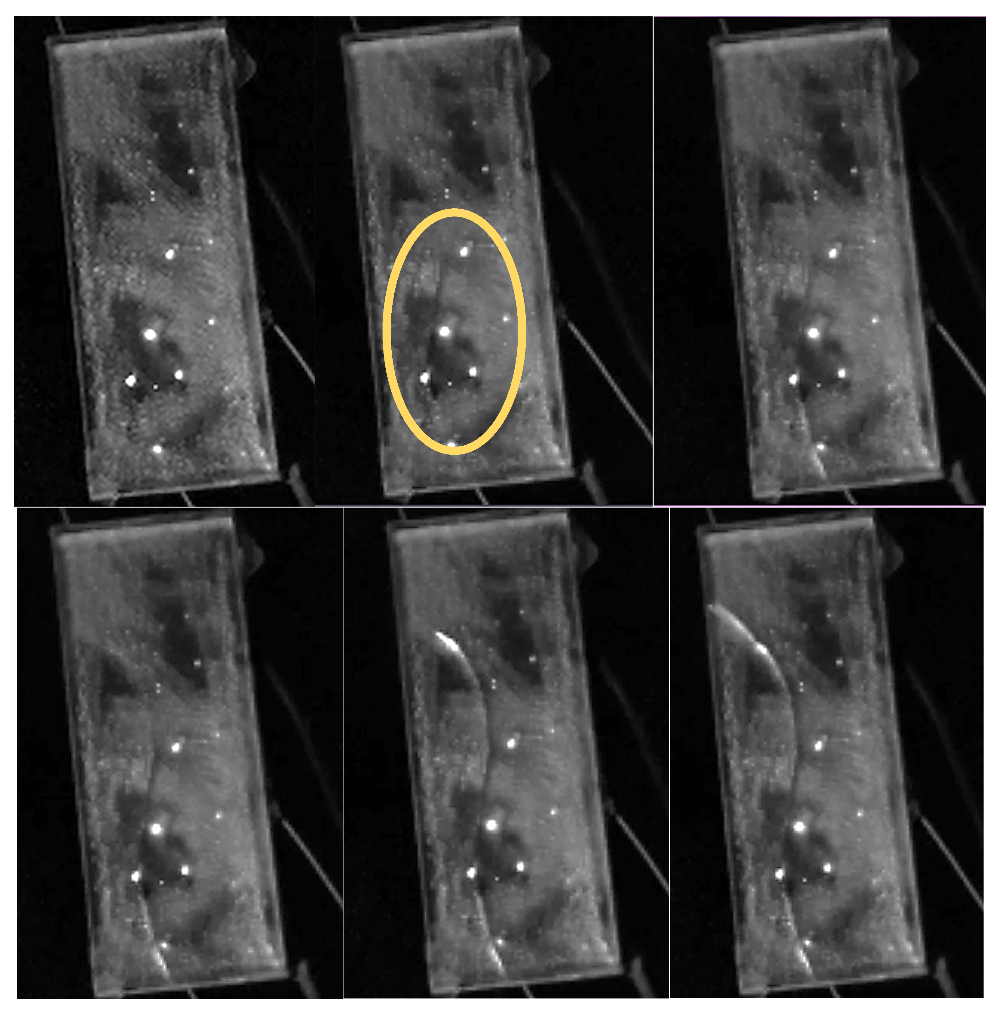
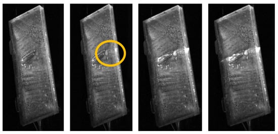
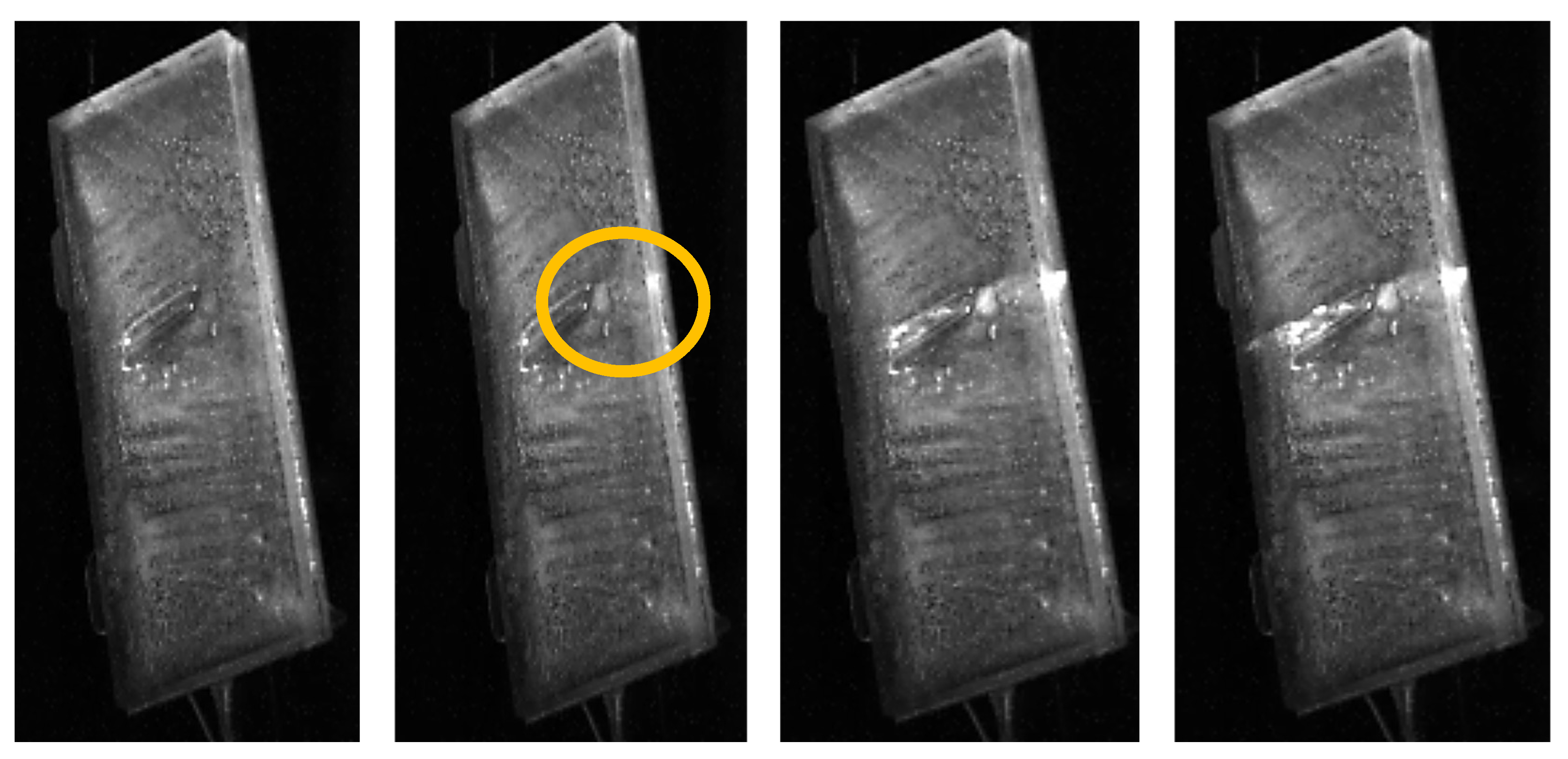
In all cases, a complete crack was visible by the end of a single frequency sweep, once the maximum stress was reached, and appeared at once across the plate. However, high-speed camera footage showed that fracture propagation was not instantaneous. Instead, the crack gradually developed over three vibration cycles before fully propagating through the ice. As shown at Figure 4, fracture was first obtained at the center of the plate, then expanded towards the edge, and finally reached the edges for complete fracture of the ice layer in the width direction. The high FPS allowed us to obtain multiple frames per vibration cycle, confirming how fracture is obtained (Supporting Information: Video S1: Mode 1—Cohesive Crack Propagation).
Figure 4.
Evolution and propagation of the ice fracture for Resonant Mode 1 on aluminum captured by a high-speed camera (
The results presented in Table 2 indicate a tensile stress of 2 MPa. This value is believed to initiate the first crack in the ice layer. If fracture propagation process is considered, the stress intensity factor (SIF) is a parameter in fracture mechanics that quantifies the intensity of the stress field near a crack tip. It accounts for the applied load, crack size, and specimen geometry in a single value. When the stress intensity factor reaches the material’s critical value, called material fracture toughness, unstable fracture occurs. Therefore, to determine the fracture toughness of ice, it is necessary to evaluate the stress intensity factor. Since cracking of the ice is obtained at the center of the plate under a Mode 1 bending regime, namely crack opening, the SIF can be evaluated by [39,40]:
with the geometry factor in tension and in bending, the normal stresses in tension and in bending, a half the crack length and b distance of the center of the crack from the edge. Since the vibration of the plate mainly generates bending, the tension part of the equation is set the zero. Since fracture propagates when the stress intensity factor equals the fracture toughness of the material (), applying this formulation to the cases studied yields the value of fracture toughness under Mode 1 for mold ice, presented in Table 3. The results show that mold ice fracture toughness is 0.22 ± 0.02 MPa, with a crack length of 25 ± 2 mm, which is consistent with the values reported in the study by Xu et al. [41]. Both sets of measurements fall within the same range. The accuracy of these preliminary measurements will be improved by optimizing the camera parameters’ FPS and crack length measurement.
Table 3.
Average value for crack propagation under Mode 1 loading.
3.2.2. Aluminum Substrate—Mode 3
Mode 3 is also a flexural mode, with bending obtained in the width direction. As for Mode 1, the cracks appeared at the location and in the direction of maximum normal stress excitation, as shown in Figure 5. This was repeatable between the three test repetitions performed. However, the propagation of the crack was not always straight for all the tests. Indeed, once cracking was initiated at the maximum stress position, meaning the center of the width of the plate, crack propagation followed for each subsequent vibration cycle. While crack propagation stayed mostly straight, it sometimes slightly curved, following weaker directions in the ice layer matrix. This is something common for fracture propagation in brittle materials [41]. In one case, fracture was obtained on both ends during the same frequency sweep, leading to cracks propagating in a similar fashion (Figure 5).
Figure 5.
(a) Modal shape and (b) double fracture propagation in the ice layer for Resonant Mode 3.
Table 4 presents the values obtained for the three test repetitions. From an analytical perspective, the stress values at crack initiation, with an average of 1.75 ± 0.01 MPa, show strong coherence with the stresses obtained for Mode 1 and the literature. The results also demonstrate that the process was consistent and that the ice layer and its properties were reproducible from one test to another. This consistency reinforces confidence in both the experimental protocol and the numerical approach used for Mode 3 characterization. The power required to obtain cracking is higher than for Mode 1, as expected, since the rigidity of the iced plate is a lot greater in the width direction and since the frequency is higher, leading to higher power consumption of the actuator.
Table 4.
Resonant Mode 3 cracking results for the aluminum substrate.
Cracking initiated at the edge of the plate (as in Figure 5) for two of the three tests, while for one test it initiated in the ice layer itself, as shown in Figure 6. The image from the high-speed camera confirms that, for Mode 1, crack propagation is not instantaneous but propagates through multiple vibration cycles, meaning multiple loading/unloading of the stresses. For the test case of Figure 6, five cycles were required to propagate the crack across the ice layer. The results presented in Table 4 give the bending stress acting on the ice but do not detail the fracture toughness for the propagation process (Supporting Information: Video S2: Mode 3—Cohesive Crack Propagation).
Figure 6.
Image of fracture propagation on aluminum substrate for Resonant Mode 3 (
Again, the stress intensity factor (SIF) at the crack tip is evaluated. For the present case, the crack initiates in the ice layer and propagates vertically in both directions along the plate height. For this test, the equation used for Mode 1 is still applicable. For the two test cases where the fracture is initiated at the edge of the plate, which is also a Mode 1 opening mechanism under bending, the corresponding SIF can be expressed as [42]:
where a is the crack length and the bending stress. Table 5 presents the fracture toughness obtained when the ice is excited by resonant Mode 3, with an average value of 0.30 ± 0.04 MPa√m. Again, the values are in line with those obtained with Resonant Mode 1 and those found in the literature [41].
Table 5.
Fracture toughness for Resonant Mode 3 under Mode 1 rupture for aluminum substrate.
3.2.3. Coated Substrates
Similar tests were performed with the two different coated substrates for Resonant Mode 1. Due to time limitation and possible degradation of the coating, only Mode 1 was tested for the coated plates since this mode is more suitable to generate delamination. No effect on cohesive cracking is expected for the coatings, since they are applied for ice/substrate interaction. At least three repetitions were performed for each substrate. Since the coatings are designed to reduce adhesion between the ice and the plate, no impact on the cracking behavior of the ice layer was observed for the coated plates, as expected. Table 6 and Table 7 show results obtained for Coating 1, with an average stress of 2.2 ± 0.4 MPa and fracture toughness of 0.28 ± 0.06 MPa√m, which are similar to the ones obtained with the bare aluminum plate. However, for the first test repetition with Coating 1, the fracture did not initiate in the middle of the plate, as compared to other tests, but on the edge of the plate, as shown in Figure 7. As for the other Resonant Mode 1 tests, three vibration cycles were also necessary to obtain a complete transverse crack. For this single test case, Equation (2) was used to calculate the stress intensity factor determining the fracture toughness. The results show that both coatings do not impact the fracture initiation and propagation in the ice layer itself.
Table 6.
Resonant Mode 1 cracking results for Coating 1.
Table 7.
Fracture toughness for Resonant Mode 1 under Mode 1 rupture for Coating 1.
Figure 7.
Image of fracture propagation on Coating 1 for Resonant Mode 1 captured by high-speed camera (
3.3. Ice Delamination with Resonant Mode 1
3.3.1. Aluminum Substrate
Frequency sweeps around the resonant mode were performed on the iced plate with the objective of initiating and observing progressive delamination of the ice layer. With the high flexion generated by the flexural mode, cracking of the ice layer was always observed at low voltage first, as detailed in the previous sections. Once cracking was obtained, the tests were pursued with additional frequency sweeps at higher voltage until gradual delamination was observed and finally total delamination and detachment of the ice layer from the substrate was obtained.
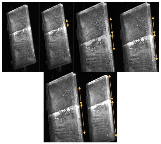
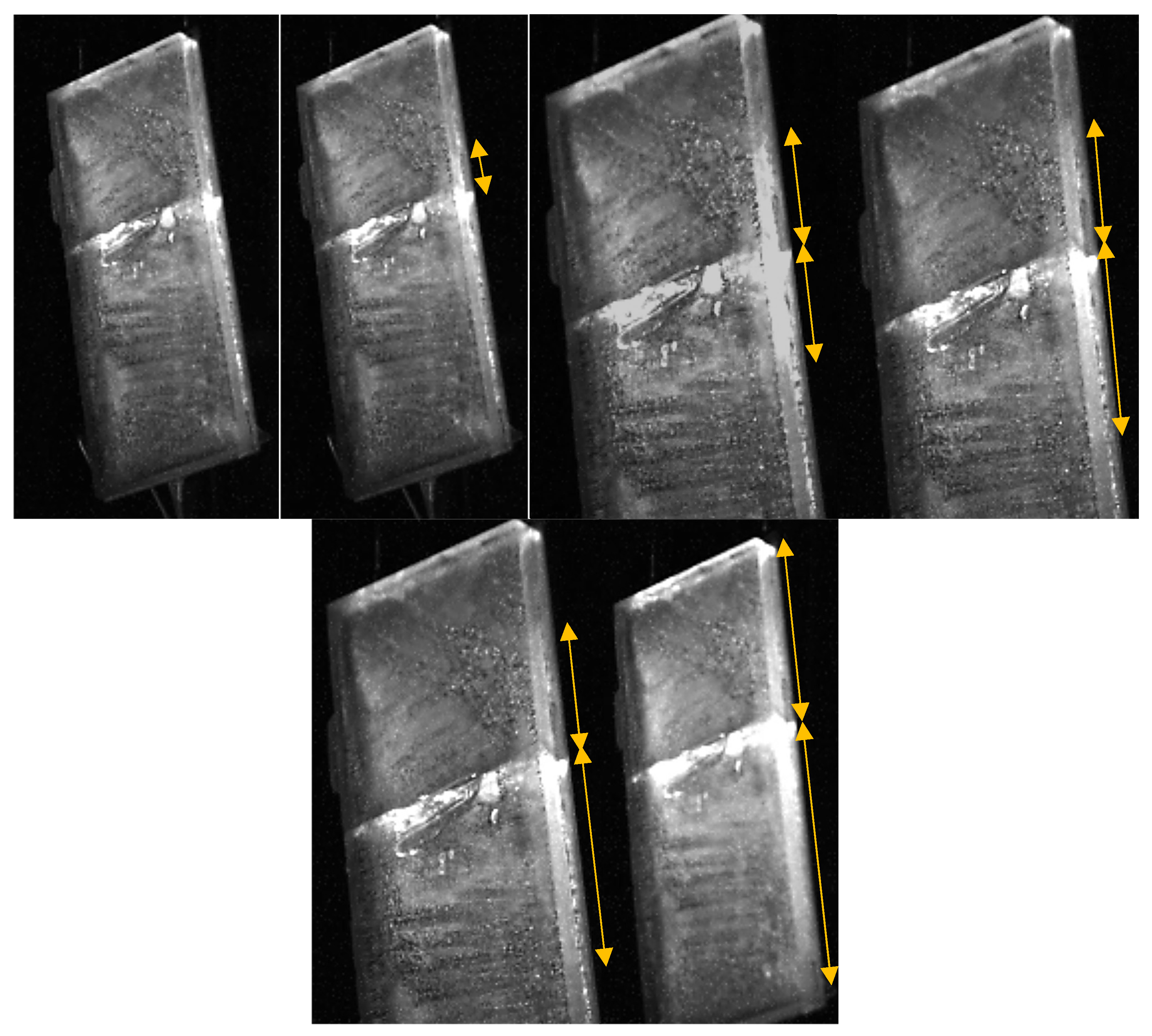
Table 8 presents the data collected for the total delamination and detachment of the ice layer from the plate for the first test performed. The results in Table 8 and Figure 8 demonstrate that delamination is obtained gradually over multiple frequency sweeps. Higher power is required for each subsequent frequency sweep to pursue the delamination of the ice layer for each test case. Previous studies in the literature have demonstrated that peeling and normal stresses are responsible for the delamination for that configuration. Numerical results confirm that those stresses are the prominent stresses at the ice layer interface and that they are at their maximum at the root of the cohesive fracture. A first partial delamination is obtained on each side of the cohesive crack for lengths of 15 mm, which is typical for a strength base failure [43]. The stresses to obtain this delamination are between 1.06 MPa and 1.49 MPa, which is again in the expected range of adhesion between aluminum and mold ice.
Table 8.
Mode 1 delamination results for the aluminum substrate for test 1 (see Figure 8).
Figure 8.
Gradual delamination process of the ice layer for five different frequency sweeps at different powers with aluminum for the first test repetition (Supporting Information: Videos S3–S7: Mode 1—Delamination).
After that first delamination, it can be observed that even if voltage is increased, acceleration of the plate is consistently lower for each subsequent sweep. This means that, with the partial uneven delamination generated, the new geometry and rigidity configuration of the iced plate result in a weaker Resonant Mode 1. This led to a decrease in stress generated at the ice layer interface. For this configuration, only fracture in Mode 1 (opening) is considered since Mode 2 (shear) is negligible, as established in [44]. The calculation of the stress intensity factor in Mode 1 opening for this configuration can be estimated by [42]:
with the delamination length, and varying between 1 and 2.1 in the function of the ratio of the delamination length and the half-length of the plate. The increase in delamination length combined with the reduction of the stress generated by the lower vibration led to stable values of the Mode 1 fracture toughness for the mold ice/aluminum interface. The values range from 0.25 to 0.36 MPa√m, which is consistent with values obtained for the other test repetitions, with an average toughness of 0.31 ± 0.05 MPa√m.
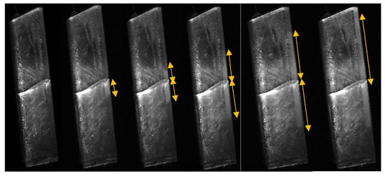
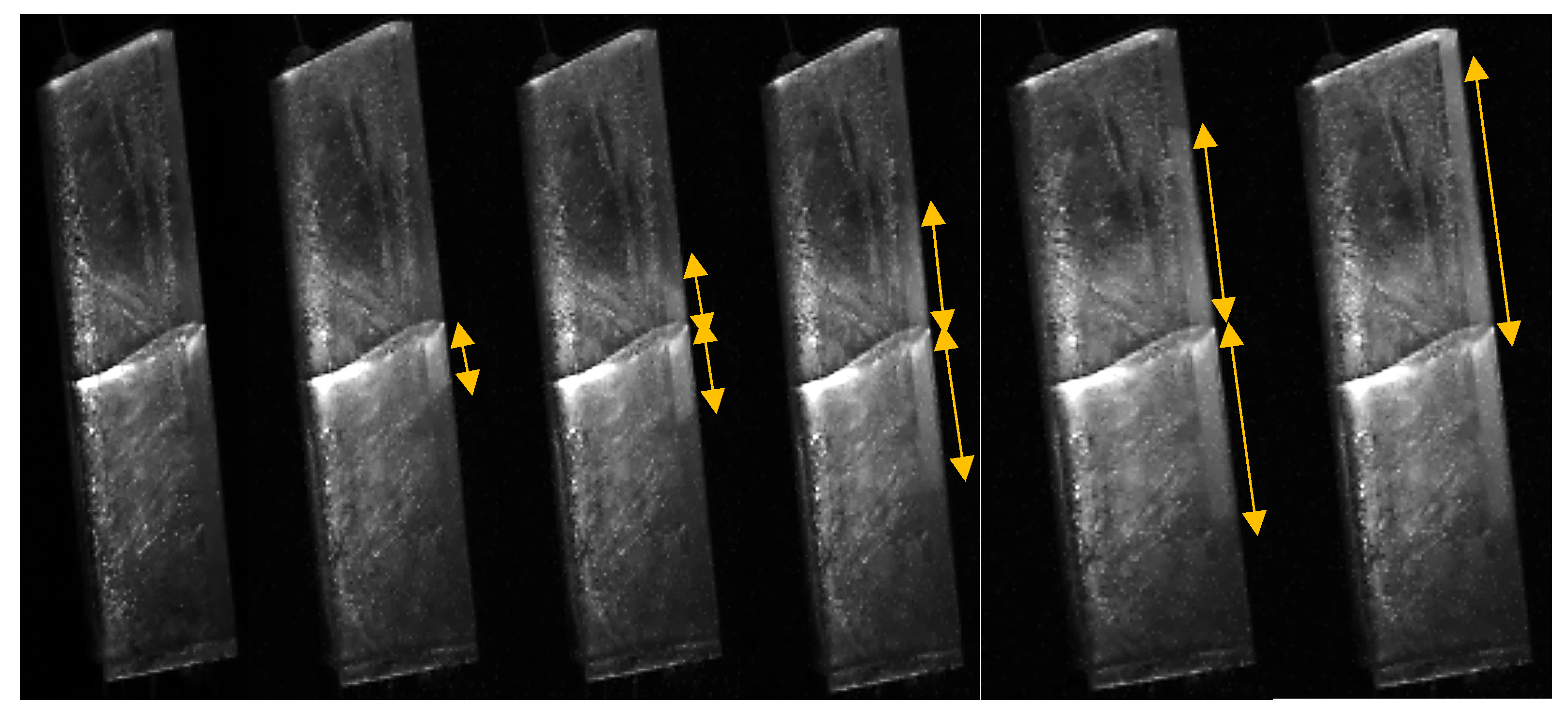
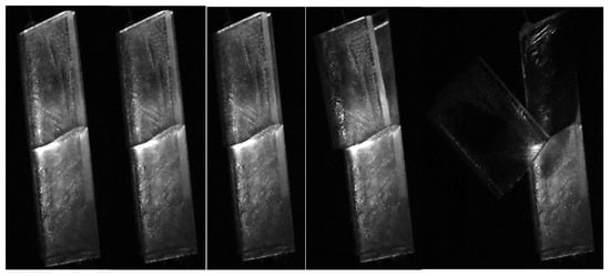
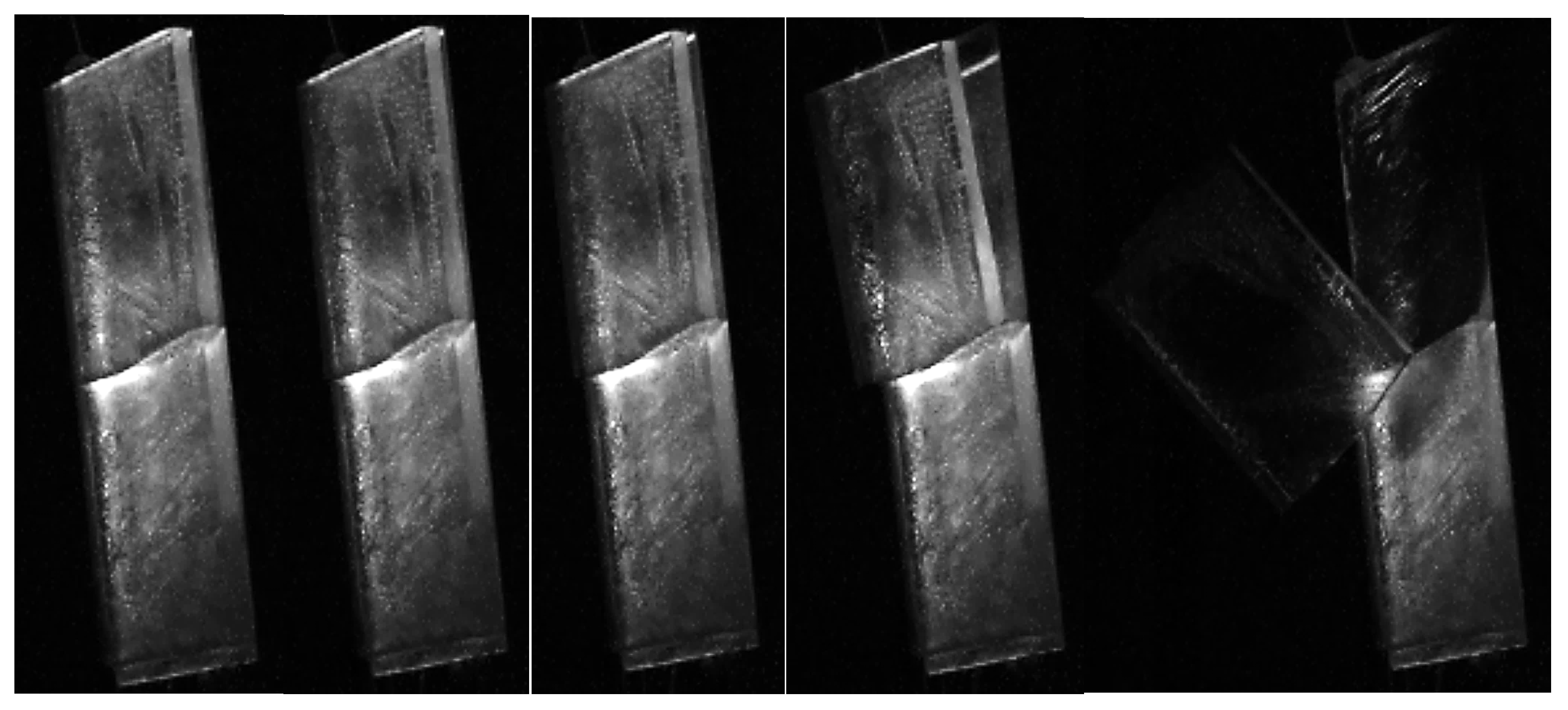
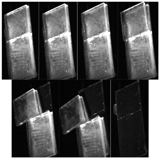
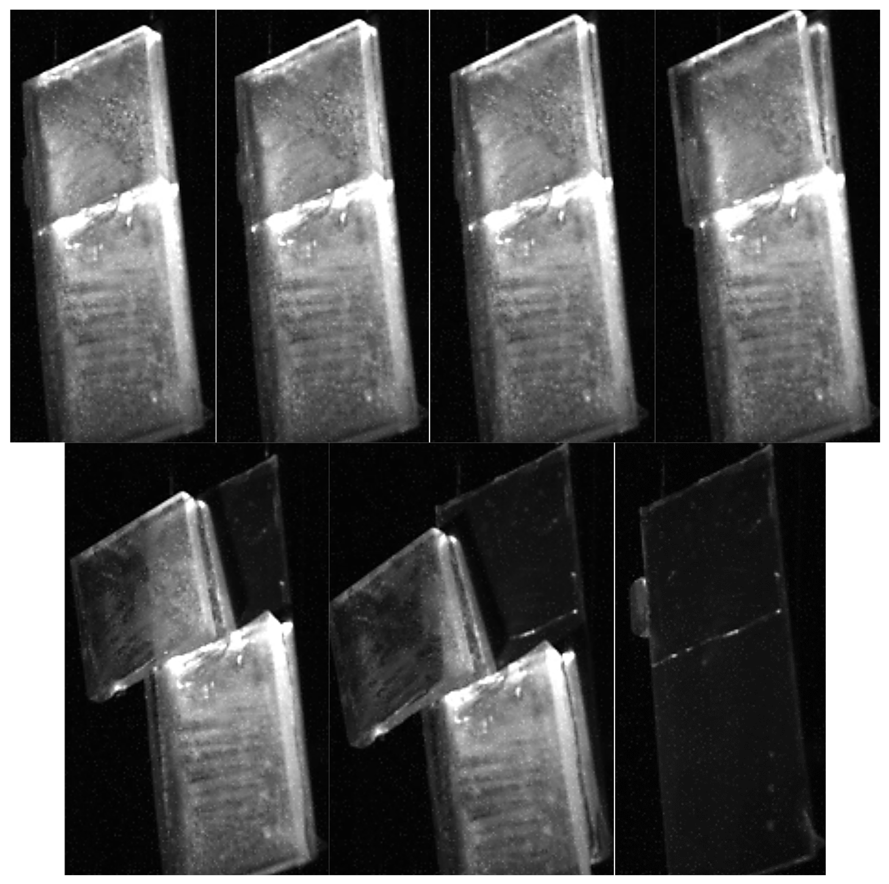
After the gradual delamination obtained during the five different frequency sweeps at different voltages, detachment of the ice layer was finally obtained from the plate during a sixth sweep. The edges of the top part of the ice layer finally delaminated, freeing the block from the plate, as shown in Figure 9. Once liberated from this mass, the plate was then freer to vibrate, and the increase in vibration generated the final delamination of the bottom block and its detachment from the plate, during the same sweep, completely removing all the ice from the aluminum plate for total de-icing (Figure 10).
Figure 9.
Detachment of the top block of ice from the aluminum plate under Mode 1 vibration during the sixth frequency sweep.
Figure 10.
Detachment of the bottom block of ice from the aluminum plate under Mode 1 vibration during the sixth frequency sweep.
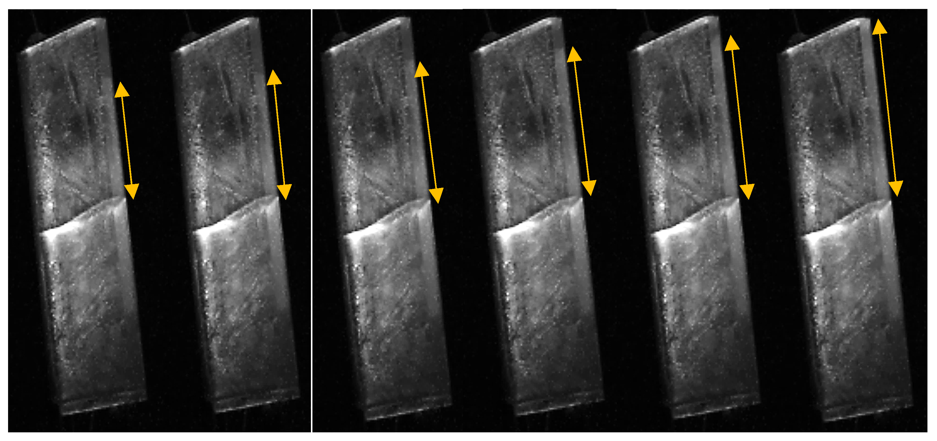
Gradual delamination during a single sweep is obtained for a significant length, ranging from 10 to 30 mm. This propagation is not instantaneous and is also obtained gradually during a single sweep. Figure 11 shows the progressive delamination process during the fifth sweep where the last 15 mm of the top block of ice is delaminated. The delamination occurred over five different vibration cycles, demonstrating the complexity of the phenomena involved.
Figure 11.
Progressive delamination over five vibration cycles of the top block of ice during the fifth frequency sweep (
3.3.2. Coated Substrate
The same process as for the aluminum plate was repeated for the coated plates, with multiple frequency sweeps performed around the resonant mode to observe the effect of the surface coatings on the delamination of the ice layer. This allowed us to observe if the test method could yield relevant results on the performances of ice-phobic coatings when subject to dynamic excitation.
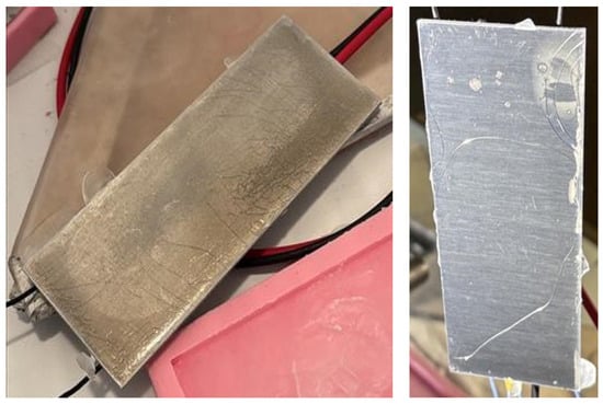
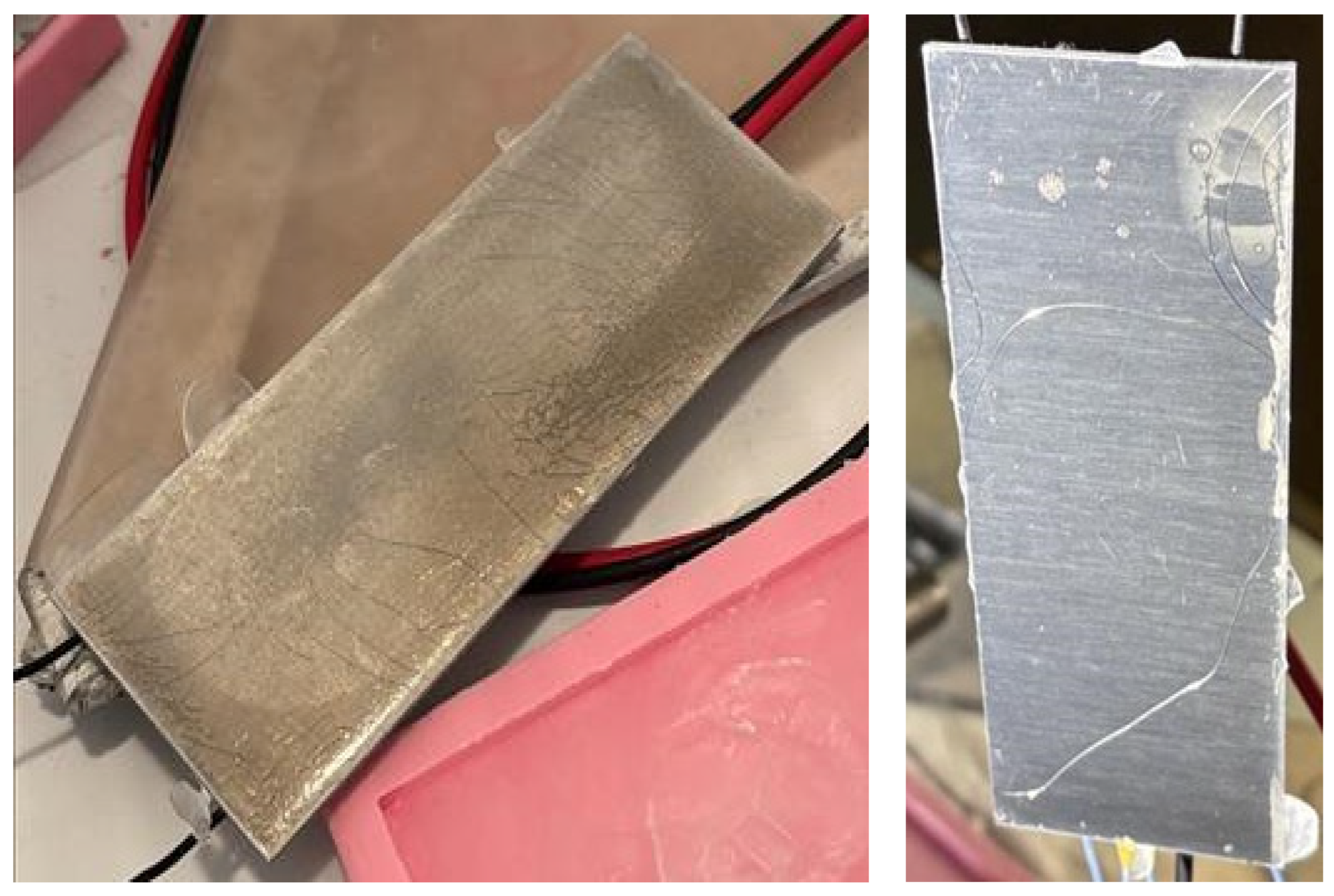
The first coating tested was Coating 1, the silicone–acrylic ice-phobic formulation, which had been cured in an oven at 160 °C for 20 min. Under low-temperature conditions, this coating exhibited brittle behavior, and when subjected to the cyclic mechanical stress generated by the piezoelectric actuator, the film developed micro-cracks across its surface (Figure 12). These cracks significantly altered the interfacial properties of the coating, increasing the adhesion strength of the ice and preventing delamination even at the maximum possible voltage applied to the actuators. Although this silicone–acrylic coating performed well in conventional ice adhesion tests, such as Centrifuge Adhesion Tests (Table 1), its poor flexibility and brittle nature under dynamic solicitation made it less efficient than bare aluminum in the vibration-based de-icing configuration. The severe mechanical degradation of the coating during testing was identified as the main reason for the poor performance, indicating that further optimization of the coating’s mechanical resilience and flexibility at low temperatures is required to improve its compatibility with active piezoelectric de-icing systems. This behavior is consistent with the glass transition temperature (Tg) of that oven-cured formulation, measured at 10 ± 5 °C, which places the coating in its glassy state at the −15 °C testing temperature used throughout this study. In this regime, the polymer network is significantly stiffer and less able to accommodate the cyclic strains imposed by the piezoelectric actuation, favoring the initiation and propagation of micro-cracks observed in Figure 12.
Figure 12.
Cracks in the coating layer for Coating 1 after a de-icing test.
These results highlighted the importance of performing tests under dynamic solicitations to accurately characterize the performance and durability of ice-phobic coatings. To further investigate the influence of curing conditions on coating behavior, Coating 1 (the silicone–acrylic ice-phobic formulation) was reapplied using the alternative curing method. In this case, the coating film was cured at room temperature for seven days under ambient laboratory conditions before testing.
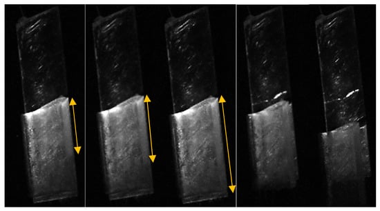
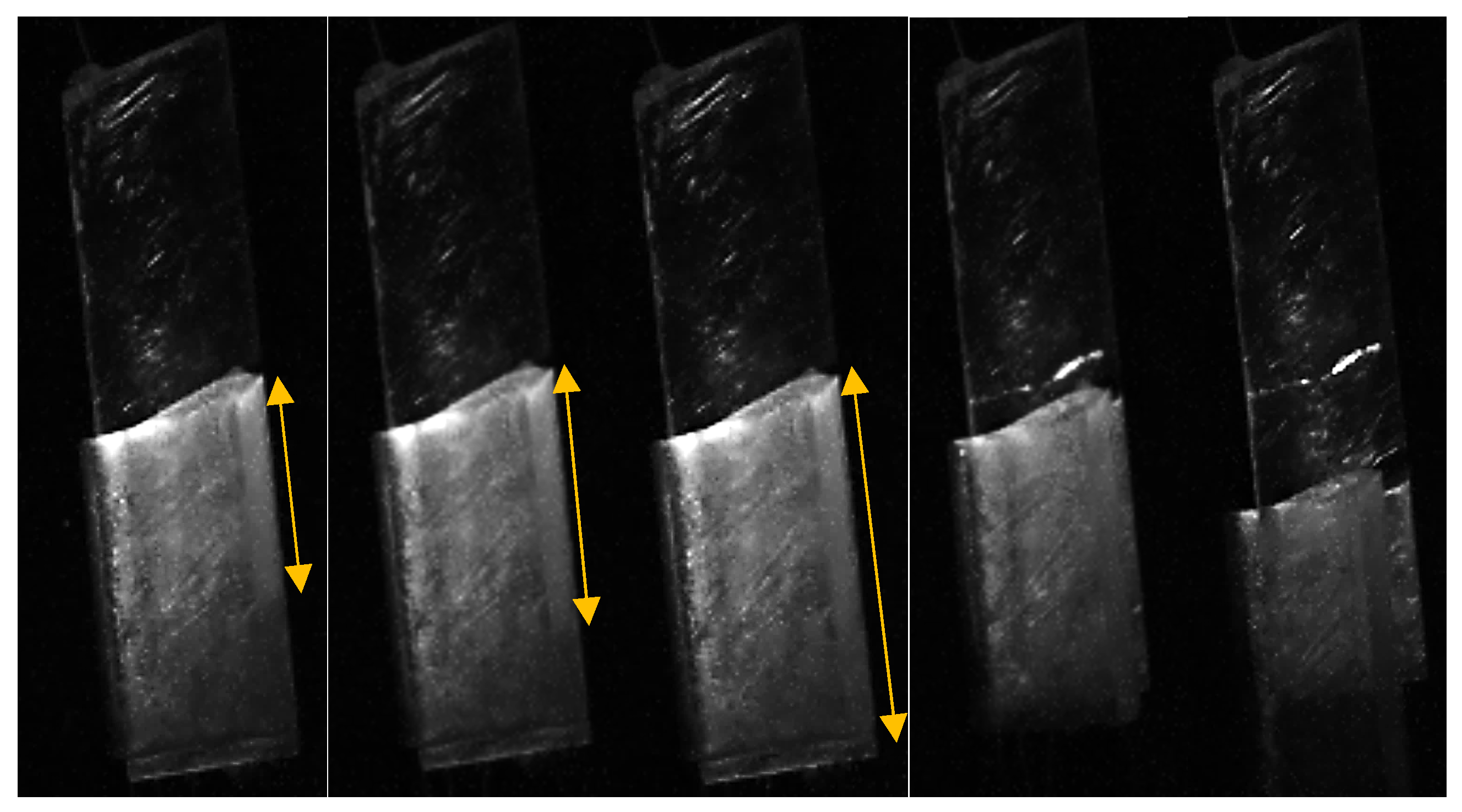
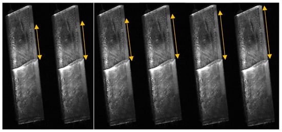
These modifications were very efficient in adapting the product to be used under dynamic loads. The delamination process for Coating 1 following these modifications was similar to the bare Aluminum surface, as shown in Figure 13 and Figure 14. As for aluminum, cracking of the ice layer was always observed first, and then gradual delamination was observed, up to total delamination and detachment of the ice layer from the substrate. Results obtained for the first test with that coating are presented in Table 9. The results show that lower voltages are required to first initiate the delamination up to the complete delamination of the ice layer. Power ranges from 0.4 W to 1.7 W, compared to values ranging from 1.7 W to 5.6 W for the aluminum substrate, meaning the delamination requires about four times less power due to the presence of Coating 1. This reduction in power is obtained due to the lower fracture toughness at the interface, with an average of 0.16 MPa√m compared to an average of 0.28 MPa√m for the aluminum, for a reduction factor close to 2 in favor of Coating 1. Furthermore, no degradation in performance was observed across all test repetitions performed with this coating, with toughness values remaining within the same range, for an average toughness value of 0.17 ± 0.05 MPa√m, further confirming the positive effect of the new curing method. This improvement can be attributed to the significantly lower Tg of the ambient-cured formulation, measured at −70 ± 5 °C, which remains well below the −15 °C testing temperature. As a result, the coating remains in its rubbery state during testing, allowing it to accommodate cyclic mechanical strain without developing the micro-cracks observed for the oven-cured formulation, consistent with the absence of surface degradation.
Figure 13.
Gradual delamination process of the ice layer for five different frequency sweeps at different powers with Coating 1 for the first test repetition.
Figure 14.
Detachment of the ice from Coating 1 under Mode 1 vibration during the sixth frequency sweep.
Table 9.
Mode 1 Delamination results for the Coating 1 substrate for the first test repetition.
Figure 14 shows that the ice layer is completely delaminated from the coating after the five frequency sweeps. However, the edges of the ice layer are still attached to the edges of the plate, and possibly to the sides of the plate. This means that while the coating is efficient at reducing the power and stresses required to obtain complete delamination, because of the ridge of the ice layer on the edges, the same power as for the aluminum substrate is necessary to obtain complete ice detachment. This is an important consideration when combining mechanical de-icing with passive surface coatings. This suggests that, near the plate edges, ice adhesion is likely governed by attachment to the uncoated sides of the plate rather than the coating’s interfacial properties. In addition, the free edges of the plate represent a sharp geometric discontinuity where stress distributions differ from the bulk surface, which can locally affect the delamination process within both the ice and at the interface, independently of the coating’s intrinsic properties. These same edge regions are also inherently more difficult to coat uniformly, often resulting in reduced coating thickness, incomplete coverage, or local defects precisely where these effects are most pronounced. This highlights an important practical consideration for component-level de-icing design: while passive coatings can significantly reduce the power required for bulk delamination, sharp geometric transitions, where stress distributions are altered and coating application is inherently more challenging, can become a limiting factor for complete ice shedding. This is particularly relevant for real structural components, which typically feature far more geometric discontinuities (edges, corners, fasteners, panel joints) than simplified laboratory samples used in most studies.
Coating 2 was also tested in the same manner as the other substrates. Coating 2 is a commercial product sold for its super hydrophobicity and supposedly good ice-phobicity. During the first two test repetitions, the coating was very effective for the de-icing of the plate. As presented in Table 10, the delamination and detachment of the ice layer was obtained during a single sweep and was almost instantaneous, with no gradual delamination observed. During a single sweep, the bottom part of the ice fell at a power of 1.1 W while the top part detached and fell during a second sweep at a power of 2.4 W, showing a reduction of about 2 to 4 with the aluminum substrate. Since no gradual delamination could be observed, it was not possible to evaluate the fracture toughness at the interface. The absence of gradual delamination for Coating 2 suggests a shift toward a stress-based failure mode instead of a fracture-based one, highlighting the importance of exploring and understanding fracture mechanics for ice shedding. Also, unlike the uniform, quasi-static shear stress applied directly to the interface during centrifuge testing, vibration-induced removal depends on the plate first reaching a sufficient dynamic response, governed by mode shape, damping, and inertia, before the interfacial strength is locally exceeded. This difference in loading mechanism may explain why the power reduction achieved does not directly scale with the much larger adhesion reduction measured by centrifuge testing and represents another important aspect that needs to be studied to better understand vibration-based de-icing. During the third repetition however, no detachment nor delamination was observed with Coating 2. This commercial coating is well-known for having a very low mechanical resistance, and the two de-icing tests created enough wear on the product that its performances were drastically lowered, well below that of bare aluminum. The results obtained with the two coatings confirmed that they can be an efficient solution to reduce the ice/substrate interface toughness, which can greatly help active systems using dynamic mechanical solicitations. However, coating resistance and flexibility is an important design parameter for the elaboration of such products.
Table 10.
Mode 1 delamination results for the Coating 2 substrate for test 1.
4. Conclusions
This paper presents a preliminary experimental investigation of ice properties and ice-coating interaction under dynamic loading using a simple yet informative test method. To advance the understanding of vibration-based de-icing systems, it is essential to characterize how cohesive failure within the ice and adhesive failure at the ice–substrate interface occur under cyclic solicitation. The proposed method is promising, providing initial insight into the mechanisms governing ice cohesive fracture and interfacial delamination. It also enables a first evaluation of how surface coatings can reduce the power required for vibration-based de-icing and practical considerations when developing coatings for these applications. While the coatings demonstrated notable reductions in required power, they also exhibited susceptibility to cyclic loading and strain. Indeed, Coating 1 when not properly cured and Coating 2 after a few solicitations provided results worse than bare aluminum. This highlights that, beyond low ice adhesion, the mechanical properties and toughness of the coating itself are key factors for ensuring durability and compatibility within a hybrid coating–vibration de-icing approach.
However, this study primarily served as a proof-of-concept, allowing us to validate the method and identify the adjustments needed to refine the setup and methodology for future, more comprehensive investigations. Future work will focus on improving the numerical model to more accurately capture the delamination process and its interaction with the vibration response. This includes a better characterization of the plate’s resonant behavior during non-uniform delamination, such as frequency shifts, acceleration drops, and changes in modal shape. To achieve this, additional accelerometers or a laser vibrometer should be used to monitor the vibration field throughout the delamination sequence. Even if, due to the symmetry of the structure and the mode excited, the monitored position remains the one with the highest vibration levels throughout the test, along with the edges, a more comprehensive spatial resolution will greatly improve characterization of the vibration field. These measurements will provide essential insights into the mechanics of ice-layer detachment and will support the refinement of the numerical model, leading to more accurate predictions of stresses and interfacial toughness. It should also be noted that all experimental tests in this study were performed using laboratory-prepared mold ice, which possesses distinct microstructure and mechanical properties compared with atmospheric icing conditions, limiting the direct transferability of the reported results to real operational scenarios. Mold ice was chosen here for its simplicity of preparation and reproducibility, which were essential to validate the proposed experimental method and fracture-based framework. The next step is to perform a comprehensive investigation on atmospheric ice formed under various conditions to obtain representative results with the fully validated and operational setup. In parallel, simple static peeling tests could be developed to independently evaluate the interface toughness between the ice and the substrate and compare the results between static and dynamic excitation. Finally, once the concept and experimental setup are optimized, the methodology will be extended to investigate a wider range of ice types produced in both the cold-room and the icing wind tunnel.
Supplementary Materials
The following supporting information can be downloaded at https://www.dropbox.com/scl/fi/rtbv0fsfeek3cibvccuwb/support-information.zip?rlkey=9kw160lkewdoxt14ovimnsaq1&st=tyshn4kw&e=1&dl=0, Video S1: Mode 1—Cohesive Crack Propagation; Video S2: Mode 3—Cohesive Crack Propagation; Videos S3–S7: Mode 1 Delamination.
Author Contributions
Conceptualization and methodology, E.V., A.L. and F.E.; software, E.V. and A.L.; validation, E.V. and G.M.; formal analysis, E.V., A.L. and F.E.; investigation, E.V. and F.E.; data curation, E.V., A.L. and F.E.; writing—original draft preparation, E.V. and A.L.; writing—review and editing, F.E., R.J. and G.M.; supervision, E.V. and G.M. All authors have read and agreed to the published version of the manuscript.
Funding
This research was supported by the Natural Sciences and Engineering Research Council of Canada (NSERC) under the Alliance Grant ALLRP 580753-22, in collaboration with Prima-Québec, Pattern Energy, and Zentek Ltd.
Data Availability Statement
The data presented in this study are available on request from the corresponding author.
Acknowledgments
The authors would like to thank Luc Chatigny and Carol Mercier at the Anti-Icing Materials International Laboratory (LIMA), UQAC, for their assistance in developing the experimental setup.
Conflicts of Interest
The authors declare no conflicts of interest.
References
- Poots, G.; Makkonen, L. Models for the growth of rime, glaze, icicles and wet snow on structures. Philos. Trans. Math. Phys. Eng. Sci. 2000, 358, 2913–2939. [Google Scholar] [CrossRef] [Scilit]
- Fikke, S.M.; Ronsten, G.; Heimo, A.; Kunz, S.E.; Ostrozlik, M.; Persson, P.E.; Sabata, J.; Wareing, B.; Wichura, B.; Chum, J. COST-727: Atmospheric Icing on Structures Measurements and Data Collection on Icing: State of the Art; Publication of MeteoSwiss: Zürich, Switzerland, 2006; p. 110. [Google Scholar]
- Laforte, J.L.; Allaire, M.A.; Laflamme, J. State-of-the-art on power line de-icing. Atmos. Res. 1998, 46, 143–158. [Google Scholar] [CrossRef] [Scilit]
- Parent, O.; Ilinca, A. Anti-icing and de-icing techniques for wind turbines: Critical review. Cold Reg. Sci. Technol. 2011, 65, 88–96. [Google Scholar] [CrossRef] [Scilit]
- Poots, G.; Gent, R.W.; Dart, N.P.; Cansdale, J.T. Aircraft icing. Philos. Trans. Math. Phys. Eng. Sci. 2000, 358, 2873–2911. [Google Scholar] [CrossRef] [Scilit]
- Heydarian, S.; Momen, G.; Jafari, R. Icephobicity and electrical assessment of slippery coating impregnated with a stabilized hydroxyl-terminated lubricant for high voltage insulation application. J. Mater. Sci. 2023, 58, 9264–9281. [Google Scholar] [CrossRef] [Scilit]
- Minoofar, G.; Kandeloos, A.J.; Koochaki, M.S.; Momen, G. Progress in Icephobic Coatings for Wind Turbine Protection: Merging Chemical Innovation with Practical Implementation. Crystals 2025, 15, 139. [Google Scholar] [CrossRef] [Scilit]
- Muhammed, M.; Harvey, D.; Khawaja, H.A.; Virk, M.S.; Momen, G. In-cloud ice accretion and performance degradation of UAV propellers in forward flight: An experimental study. Cold Reg. Sci. Technol. 2025, 239, 104599. [Google Scholar] [CrossRef] [Scilit]
- Bragg, M.B.; Broeren, A.P.; Blumenthal, L.A. Iced-airfoil aerodynamics. Prog. Aerosp. Sci. 2005, 41, 323–362. [Google Scholar] [CrossRef] [Scilit]
- Anthony, M.; Nathoo, M.; Zhan, Z.; Habashi, W.; Fossati, M. Rotor Ice Shedding and Trajectory Analyses in Forward Flight. In Proceedings of the 2018 Atmospheric and Space Environments Conference, Atlanta, GA, USA, 25–29 June 2018. [Google Scholar]
- Rekuviene, R.; Saeidiharzand, S.; Mazeika, L.; Samaitis, V.; Jankauskas, A.; Sadaghiani, A.; Gharib, G.; Muganlı, Z.; Kosar, A. A review on passive and active anti-icing and de-icing technologies. Appl. Therm. Eng. 2024, 250, 123474. [Google Scholar] [CrossRef] [Scilit]
- He, Q.; Li, K.; Xu, Z.; Wang, J.; Wang, X.; Li, A. Research progress on construction strategy and technical evaluation of aircraft icing accretion protection system. Chin. J. Aeronaut. 2023, 36, 1–23. [Google Scholar] [CrossRef] [Scilit]
- Fakorede, O.; Feger, Z.; Ibrahim, H.; Ilinca, A.; Perron, J.; Masson, C. Ice protection systems for wind turbines in cold climate: Characteristics, comparisons and analysis. Renew. Sustain. Energy Rev. 2016, 65, 662–675. [Google Scholar] [CrossRef] [Scilit]
- Richert, F. Is Rotorcraft icing knowledge transferable to wind turbines. In Proceedings of the 3rd International Conference on Wind Energy Production in Cold Climates, Saariselkä, Finland, 19–21 March 1996; FMI: Saariselkä, Finland, 1996; pp. 366–380. [Google Scholar]
- Palacios, J.; Bailey, M.; Szefi, J. Ice Testing of a Centrifugally Powered Pneumatic Deicing System for Helicopter Rotor Blades. J. Am. Helicopter Soc. 2015, 60, 1–12. [Google Scholar] [CrossRef] [Scilit]
- Drury, M.D.; Szefi, J.T.; Palacios, J.L. Full-scale testing of a centrifugally powered pneumatic de-icing system for helicopter rotor blades. J. Aircr. 2017, 54, 220–228. [Google Scholar] [CrossRef] [Scilit]
- Zhang, Z.; Zhang, H.; Zhang, X.; Hu, Q.; Jiang, X. A Review of Wind Turbine Icing and Anti/De-Icing Technologies. Energies 2024, 17, 2805. [Google Scholar] [CrossRef] [Scilit]
- Ramanathan, S.; Varadan, V.V.; Varadan, V.K. Deicing of helicopter blades using piezoelectric actuators. In Proceedings of the Smart Structures and Materials 2000: Smart Electronics and MEMS, Newport Beach, CA, USA, 6–8 March 2000; pp. 281–292. [Google Scholar]
- Yin, C.; Zhang, Z.; Wang, Z.; Guo, H. Numerical simulation and experimental validation of ultrasonic de-icing system for wind turbine blade. Appl. Acoust. 2016, 114, 19–26. [Google Scholar] [CrossRef] [Scilit]
- Bryant, M.; Wolff, E.; Garcia, E. Aeroelastic flutter energy harvester design: The sensitivity of the driving instability to system parameters. Smart Mater. Struct. 2011, 20, 125017. [Google Scholar] [CrossRef] [Scilit]
- Villeneuve, E.; Volat, C.; Ghinet, S. Numerical and Experimental Investigation of the Design of a Piezoelectric De-Icing System for Small Rotorcraft Part 3/3: Numerical Model and Experimental Validation of Vibration-Based De-Icing of a Flat Plate Structure. Aerospace 2020, 7, 54. [Google Scholar] [CrossRef] [Scilit]
- Xu, G.; Xu, B.; Xu, C.; Luo, Y. Numerical modeling of guided ultrasonic waves generated and received by piezoelectric wafer in a Delaminated composite beam. In Proceedings of the Fourth International Symposium on Laser Interaction with Matter; SPIE: Bellingham, WA, USA, 2017; p. 1017316. [Google Scholar]
- Villeneuve, E.; Volat, C.; Ghinet, S. Numerical and Experimental Investigation of the Design of a Piezoelectric De Icing System for Small Rotorcraft Part 1/3: Development of a Flat Plate Numerical Model with Experimental Validation. Aerospace 2020, 7, 62. [Google Scholar] [CrossRef] [Scilit]
- Villeneuve, E.; Volat, C.; Ghinet, S. Numerical and experimental investigation of the design of a piezoelectric de-icing system for small rotorcraft part 2/3: Investigation of transient vibration during frequency sweeps and optimal piezoelectric actuator excitation. Aerospace 2020, 7, 49. [Google Scholar] [CrossRef] [Scilit]
- Palacios, J.L.; Zhu, Y.; Smith, E.; Rose, J. Ultrasonic Shear and Lamb Wave Interface Stress for Helicopter Rotor Deicing Purposes. In Proceedings of the 47th Structures, Structural Dynamics and Materials Conference, Newport, RI, USA, 1–4 May 2006. [Google Scholar]
- Palacios, J.L.; Smith, E.C.; Zhu, Y.; Rose, J.L.; Morrow, P. Global Ultrasonic Shear Wave Anti-Icing Actuator for Helicopter Blades. In Proceedings of the Annual Forum Proceedings-American Helicopter Society; American Helicopter Society, INC: Fairfax, VA, USA, 2007; Volume 3. [Google Scholar]
- Budinger, M.; Pommier-Budinger, V.; Napias, G.; Costa da Silva, A. Ultrasonic Ice Protection Systems: Analytical and Numerical Models for Architecture Tradeoff. J. Aircr. 2016, 53, 680–690. [Google Scholar] [CrossRef] [Scilit]
- Pommier-Budinger, V.; Budinger, M.; Tepylo, N.; Huang, X. Analysis of Piezoelectric Ice Protection Systems Combined with Ice-Phobic Coatings; American Helicopter Society, Inc.: Fairfax, VA, USA, 2016. [Google Scholar]
- Jellinek, H.H.G. Adhesive properties of ice. J. Colloid Sci. 1959, 14, 268–280. [Google Scholar] [CrossRef] [Scilit]
- Kandagal, S.B.; Venkatraman, K. Piezo-Actuated Vibratory Deicing of a Flat Plate. In Proceedings of the 46th AIAA/ASME/ASCE/AHS/ASC Structures, Structural Dynamics and Materials Conference, Austin, TX, USA, 18–21 April 2005; AIAA: Washington, DC, USA, 2005; Volume 6. [Google Scholar]
- Wang, F.; Zhuo, Y.; He, Z.; Xiao, S.; He, J.; Zhang, Z. Dynamic Anti-Icing Surfaces (DAIS). Adv. Sci. 2021, 8, 2101163. [Google Scholar] [CrossRef] [Scilit] [PubMed]
- Maio, L.; Piscitelli, F.; Ameduri, S.; Concilio, A.; Ricci, F. Combining Ultrasound and Surface Treatments for an Efficient Ice Protection. In Proceedings of the European Workshop on Structural Health Monitoring; Springer International Publishing: Cham, Switzerland, 2021; pp. 870–880. [Google Scholar]
- Strobl, T.; Storm, S.; Ameduri, S. Chapter 26—Synergic Effects of Passive and Active Ice Protection Systems. In Morphing Wing Technologies; Concilio, A., Dimino, I., Lecce, L., Pecora, R., Eds.; Butterworth-Heinemann: Oxford, UK, 2018; pp. 841–864. [Google Scholar]
- Wan, Y.; Liu, Y.; Liu, Y.; Sun, C.; Feng, K.; Wu, Y.; Zhou, F. Flexible Electrothermal Hydrophobic Self-Lubricating Tape for Controllable Anti-icing and De-icing. ACS Appl. Eng. Mater. 2023, 1, 669–678. [Google Scholar] [CrossRef] [Scilit]
- Samad, A.; Dhulipalla, A.; Hu, H. A Hybrid Anti-/De-icing Strategy for UAV Propeller Icing Protection. In AIAA Aviation Forum and ASCEND 2024; American Institute of Aeronautics and Astronautics: Reston, VA, USA, 2024. [Google Scholar]
- Palanque, V.; Villeneuve, E.; Budinger, M.; Pommier-Budinger, V.; Momen, G. Experimental measurement and expression of atmospheric ice Young’s modulus according to its density. Cold Reg. Sci. Technol. 2023, 212, 103890. [Google Scholar] [CrossRef] [Scilit]
- Palanque, V.; Villeneuve, E.; Budinger, M.; Pommier-Budinger, V.; Momen, G. Cohesive strength and fracture toughness of atmospheric ice. Cold Reg. Sci. Technol. 2022, 204, 103679. [Google Scholar] [CrossRef] [Scilit]
- Villeneuve, E.; Harvey, D.; Zimcik, D.; Aubert, R.; Perron, J. Piezoelectric De-Icing System for Rotorcraft. J. Am. Helicopter Soc. 2015, 60, 12. [Google Scholar] [CrossRef] [Scilit]
- USAF Damage Tolerant Design Handbook: Guidelines for the Analysis and Design of Damage Tolerant Aircraft Structures; Air Force Research Laboratory: Wright-Patterson AFB, OH, USA, 2002.
- American Petroleum Institute; American Society of Mechanical Engineers. API 579-1/ASME FFS-1: Fitness-For-Service; American Petroleum Institute: Washington, DC, USA; American Society of Mechanical Engineers: New York, NY, USA, 2007. [Google Scholar]
- Xu, Y.; Zhou, M.; Yi, X.; Hua, W.; Huang, J.; Zhang, W.; Dong, S. Experimental Study on Mixed-Mode (I–II) Fracture Toughness of Freshwater Ice. Acta Mech. Solida Sin. 2024, 37, 252–264. [Google Scholar] [CrossRef] [Scilit]
- Wang, C.H. DSTO Aeronautical and Maritime Research Laboratory. In Introduction to Fracture Mechanics; DSTO Aeronautical and Maritime Research Laboratory: Melbourne, Australia, 1996. [Google Scholar]
- Golovin, K.; Dhyani, A.; Thouless, M.D.; Tuteja, A. Low-interfacial toughness materials for effective large-scale deicing. Science 2019, 364, 371–375. [Google Scholar] [CrossRef] [Scilit] [PubMed]
- Gastaldo, G.; Hernández-Rodríguez, G.; Pommier-Budinger, V.; Budinger, M.; Pothin, J.; Coclite, A.M. Impact of coatings on the performance of resonant electromechanical de-icing systems. Results Eng. 2025, 27, 106636. [Google Scholar] [CrossRef] [Scilit]

Disclaimer/Publisher’s Note: The statements, opinions and data contained in all publications are solely those of the individual author(s) and contributor(s) and not of MDPI and/or the editor(s). MDPI and/or the editor(s) disclaim responsibility for any injury to people or property resulting from any ideas, methods, instructions or products referred to in the content. |
© 2026 by the authors. Licensee MDPI, Basel, Switzerland. This article is an open access article distributed under the terms and conditions of the Creative Commons Attribution (CC BY) license.