


Abstract
The results of a numerical modeling of the laminar water flow and mixed conductive–convective heat transfer in highly elongated heatsink with continuous rectangular microchannels, and a width-to-length ratio of 625 (i.e., 0.2 mm to 125 mm), are presented, along with two methods of fluid entry (along and perpendicular to the base of the heatsink) for a wide range of surface heat flux density q from 30 to 2000 kW/m2 and water volume flow rate from 10 to 50 L/h (). It has been demonstrated that: (1) The elongated microchannel maintains its effectiveness in heat removal by water, even under conditions of high q-value; however, in the terminal sections the temperature can approach the maximum permissible operating level for high-loaded silicon electronic components (~95–100 °C). (2) For microchannel heatsinks, the direction of the incoming flow is not of significant influence, since the microchannel structure, even with a height of 2.5 mm, exhibits substantial diffusivity and the flow in the inlet area rapidly turns along the heat distribution base; this flow further possesses the same characteristics as in the case of the input flow parallel to the axis of the microchannels. The developed model allows for the optimization of geometric, kinematic and thermal parameters of highly efficient microchannel devices, depending on the expected operating conditions.
1. Introduction
The development of opportunities for increasing the performance of heat exchangers for electronic components is of considerable interest due to the improvement in the technological level of production of various high-loaded electronic chips and the associated growth of heat flow per unit of steadily decreasing chip crystal area (heat flux). One of these trends is the steady introduction and spread of significantly more efficient and compact water systems in comparison with air coolers as well as with traditional water-cooling systems. Among the most progressive modern directions in the development of water-cooling systems with great potential is the technology of microchannel heatsinks, which maximizes the washed area of its ribs, thereby effectively increasing the absorbed heating power.
At present, a wide variety of advanced microchannel heatsink geometries have been developed and optimized for high-power-density electronic and nanochip cooling applications, including manifold, topology-optimized, and embedded microfluidic configurations [1,2,3,4,5,6,7,8,9,10,11,12,13]. In addition, numerous approaches have been proposed to enhance heat transfer and vortex generation within microchannels, particularly through biomimetic and bio-inspired designs that improve thermal–hydraulic performance [14,15,16].
Under the condition of mass production of microchannel structures, there is an industrial requirement for their maximum simplicity, which reduces the requirements for technology and equipment, reducing the cost of manufacturing. Therefore, the simplicity of microchannel forms in comparison with a number of exclusive designs presented in large numbers and discussed in [1,2,3,4,5,6] is one of the most important priorities on the way to effective mass adoption and implementation of this technology with great potential.
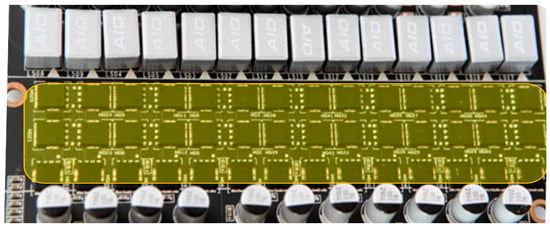
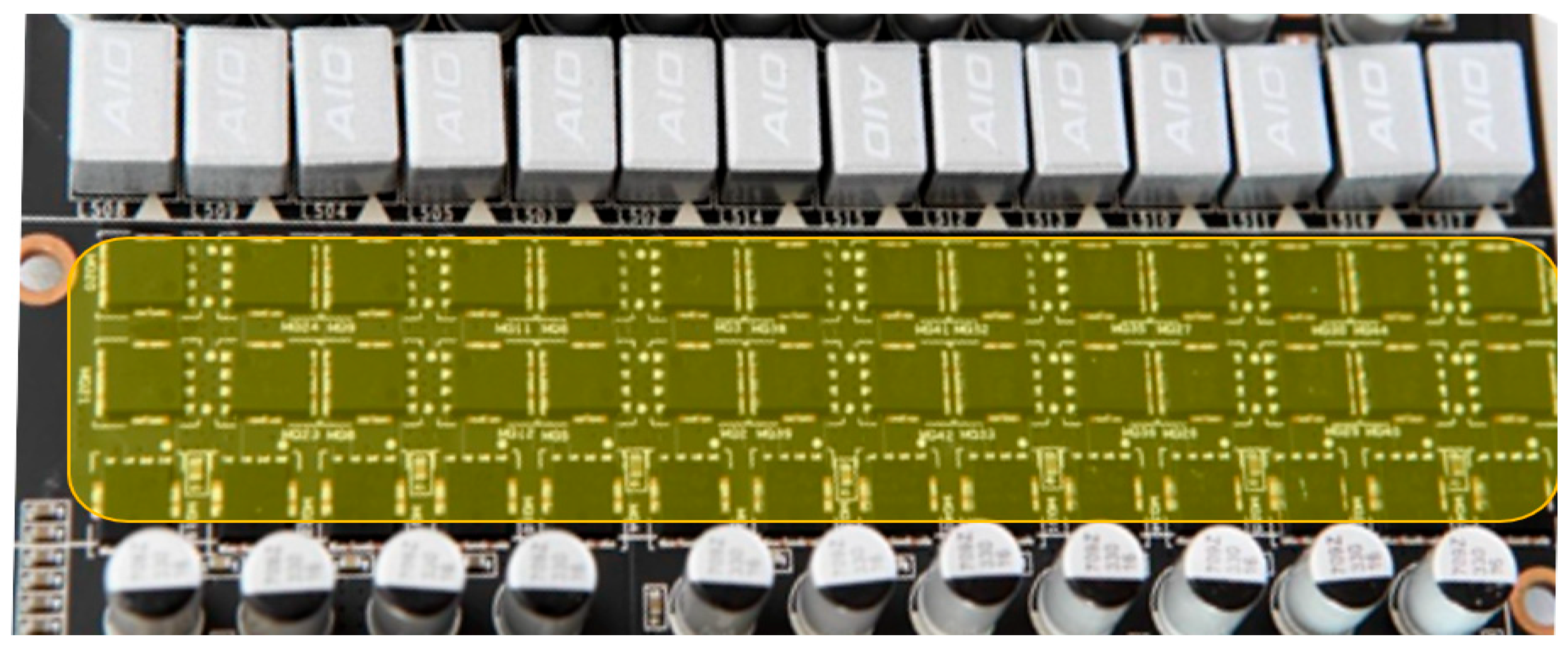
One promising mass implementation of this simplest realization of microchannel technology is a cooling heatsink of the young German company TechN “https://techn.de/ (accessed on 20 April 2026)”. This heatsink is both highly efficient and structurally simple, being compact and lightweight. The microchannels of this heatsink are milled into a metal base and are 0.2 mm wide and 0.15 mm thick. Flat ribs are also milled into the metal base. The water inlet and outlet of the heatsink are organized through a thick acrylic lid that is hermetically attached to the base. However, microchannels are delicate structures, which imply the importance of reliably determining their performance characteristics under the expected operating conditions. Moreover, usually highly loaded electronic components, for example, metal-oxide-semiconductor field-effect transistors (MOSFETs) of a multiphase power supply circuit, of video chip or processor, are arranged in a row and very tightly to each other (Figure 1), and therefore integral elongated microchannel heatsinks may be relevant as a prospect for increasing their heat transfer and the need for more efficient cooling of such arrays of electrical components.
Figure 1.
A typical dense arrangement of a MOSFET array (components in a yellow box) of a multiphase power supply circuit in a modern graphics processor unit (GPU).
But an elongated heatsink, given its microchannel design, results in highly elongated microchannels. Typical designs studied are limited to a relatively small microchannel length, usually on the order of tens of mm; however, in this case, the elongated heatsink design requires breaking down the delicate microchannel structure into a number of separate sections [1,2,3,4,5,6,11], which complicates and increases the cost of technology and manufacturing process. In this regard, it is of interest to study the thermal efficiency of long continuous microchannel structures.
In a long microchannel, the flowing liquid can significantly change the temperature, and, as a consequence, the viscosity with thermal conductivity and density; that can significantly affect the properties of the flow and heat transfer, and therefore requires study and subsequent analysis. Therefore, the purpose of this research is to study the efficiency of heat-scattering and dynamic characteristics of a heatsink with an array of highly elongated continuous microchannels of rectangular cross-section, taking into account the variability of water properties depending on local temperature changes along the flow direction. Thus, such a problem statement is intended to clarify the effects of the heatsink high elongation and inlet flow angle on heat transfer and to better understand the feasibility and features of using continuous microchannel structures of the simplest rectangular shape. And due to the desire to take into account the effect of changes in the thermophysical parameters of the water coolant along the microchannel as the temperature increases as clearly as possible, a significant number of results are presented in dimensional form in this study, unlike more traditional dimensionless representations, which helps to better establish their trends and simplify further analysis.
2. Problem Description and Its Numerical Implementation
2.1. The Object Under Study and Operational Conditions
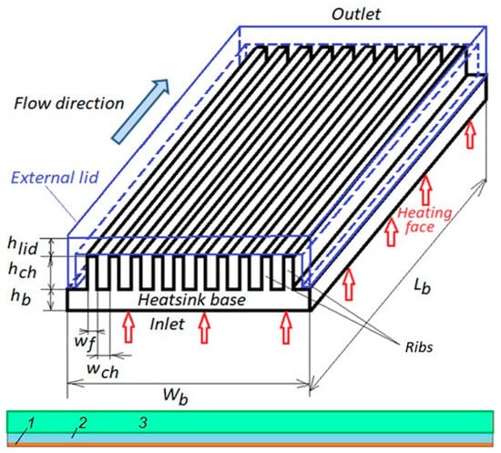
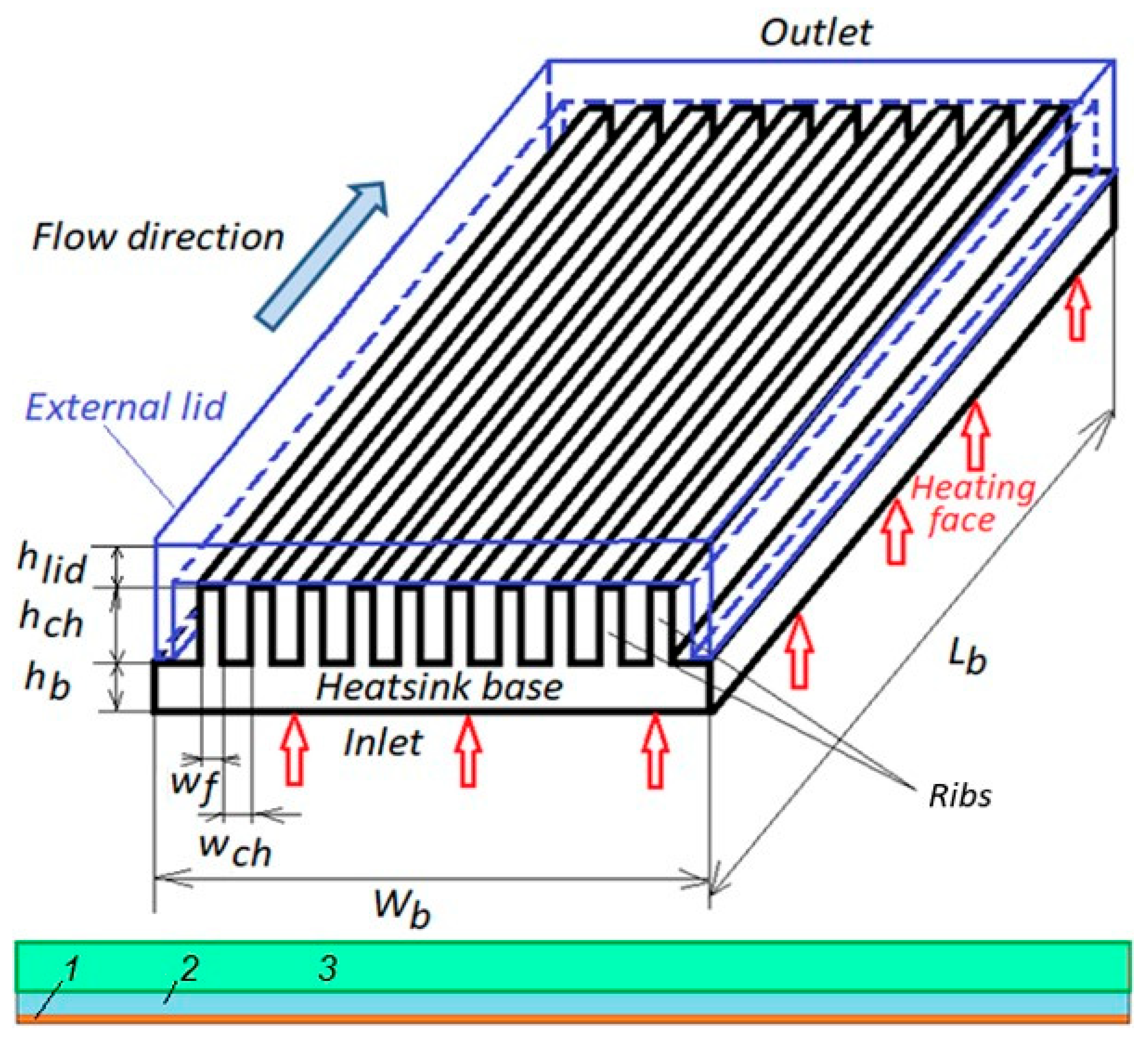
The object of study is a microchannel heatsink with the following parameters: the length of the heating base, Lb, is 125 mm; its width Wb is 30 mm and thickness hb is 1 mm; the width of the ribs wf is 0.15 mm; and the width wch and height hch of the microchannel are 0.2 mm and 2.5 mm respectively. The ratios are thus Lb/wch = 625 and hch/wch = 12.5 (Figure 2).
Figure 2.
Simulated heatsink design: 1—copper base, 2—elongated microchannel, 3—acrylic lid.
The heatsink is heated from the side of the copper base of the microchannels, and their upper and side parts are hermetically closed with a lapped massive acrylic lid having a wall thickness of hlid = 5 mm, in which the inlet and outlet of water into the internal microchannel structure is realized from the narrow sides. Thus, the basis of the microchannel geometry modeled in this study is chosen to be very similar to the advanced technological level of the design of serial industrial products achieved by TechN. However, the length of the heatsink for the purposes of this study was increased by three times. At this stage of the study, which precedes further technological development, the most effective and flexible method of preliminary assessment, based on numerical modeling, has been applied in a wide range of surface heat flux density q = 30–2000 kW/m2 (including their both homogeneous and inhomogeneous distributions along the heatsink) at a water volume flow rate of = 10–50 L/h. An important reason for choosing the numerical modeling method is that it allows more detailed information to be obtained about the distribution of temperature, pressure, viscous friction forces, thermal fluxes and other related parameters in various sections of the microchannel. It also takes into account the dependence of viscosity and thermal conductivity of water with temperature changes, as well as inside the heatsink body. It should be noted that this information cannot be obtained experimentally due to the extremely small size of microchannels.
2.2. Problem Formalization and Computational Domain
In order to solve the problem of conjugate convective heat transfer between a fluid moving in microchannels and a heatsink solid body with a complex geometry and made of various materials, it is necessary to introduce acceptable simplifications. In consideration of the symmetry of the heatsink cross-section (Figure 2) and the substantial number n = 80 of identical microchannels, it can be assumed that the distribution of temperature and the parameters of the moving fluid are uniform along the transverse coordinate z. Consequently, rather than examining the entire set of heatsink radiator channels, it is possible to define a computational domain between the planes of symmetry of two adjacent heatsink edges. This approach involves the examination of flow and heat exchange for a single microchannel bounded by thin halves of the edges (0.075 mm), a heated bottom base (1 mm), and a close-to-insulated acrylic lid (5 mm), instead of the consideration of the entire microchannel structure (Figure 3).
Figure 3.
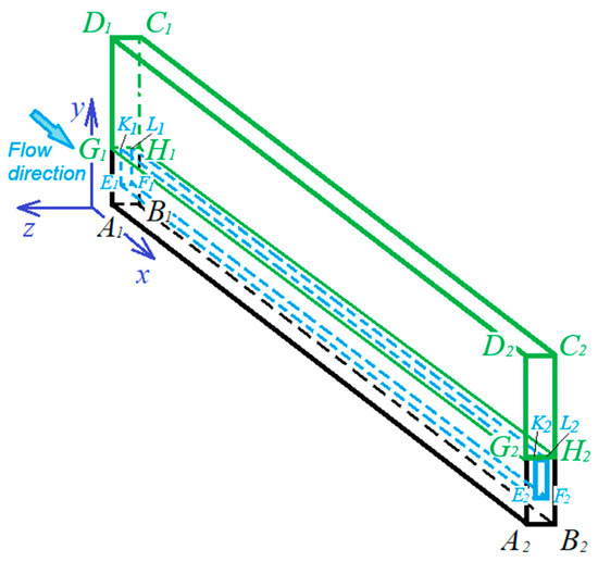
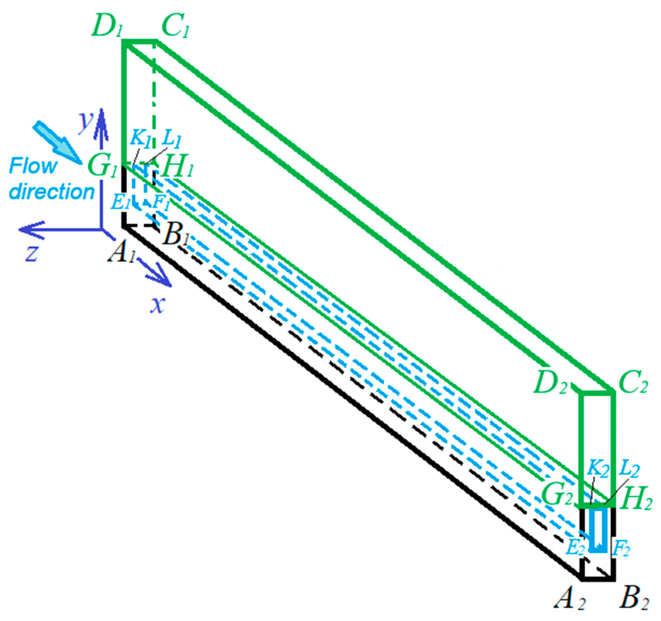
Simplified parallelepipedal computational domain, containing: a copper base section (black), a microchannel (blue), an acrylic lid section (green).
In addition, this approach significantly simplifies the geometry of the computational domain and increases the efficiency and accuracy of calculations due to a much more detailed mesh. In this instance, the computational domain is reduced to a rectangular parallelepiped, A1B1C1D1A2B2C2D2, with a rectangular channel, E1F1L1K1E2F2L2K2, inside. At the same time, it is important to mention here that, based on the problem statement (Figure 2), the studied heatsink is made of two different materials, which is accordingly reflected in the domain: the lower part, including the base and microchannel ribs, A1B1H1G1A2B2H2G2, is made of copper, while the upper much thicker lid G1H1C1D1G2H2C2D2 is acrylic. This considerably facilitates the setting of boundary conditions on the internal and external boundaries. Furthermore, this approach enables the modeling of heat exchangers with a variable number of ribs and microchannels, thereby ensuring the scalability of the proposed model with a simplified geometry. When vertical flow enters the channel, an additional rectangular hole is made in the upper face C1D1C2D2 to the level of the internal microchannel. In this case, the face A1B1C1D1 is regarded as a lid plane or a plane of symmetry.
2.3. Computational Mesh Structure and Properties
In the process of mesh generation, the following requirements were considered as priority, which traditionally increase the efficiency and accuracy of calculations:
- The mesh must be structured.
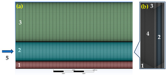
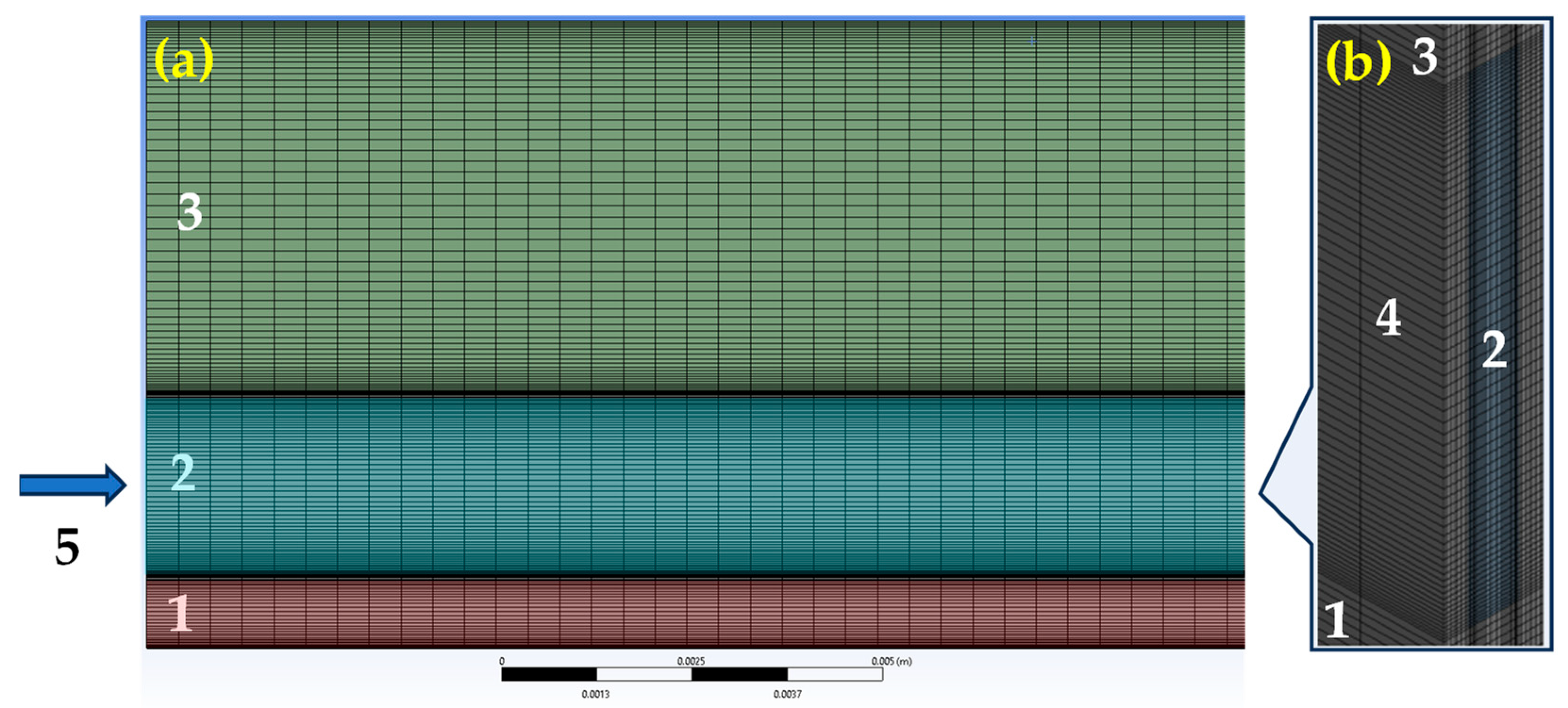
- The placement of mesh nodes, both for a solid body and, especially, for a microchannel, must be adapted to the boundaries of the microchannel by appropriate thickening to more accurately calculate heat fluxes in different media and ensure their correct conjugation. The mesh parameters with increasing resolution near the interface boundary and outer walls have been chosen in the process of computational experimentation, and the appropriate mesh is characterized by the following parameters: 2.4 million cells, 7.4 million faces, and 2.6 million nodes (Figure 4).Figure 4. Geometry of the computational mesh fragment: (a)—side face view, (b)—a mesh fragment for the input (output) domain sections in the area of the channel location in an enlarged scale for better graphic resolution. Here: 1—heatsink copper base, 2—water channel region, 3—acrylic lid, 4—ribs, 5—flow direction (hereinafter is from left to right).
A further increase in these parameters no longer leads to any physically or statistically noticeable change in the results of calculating the parameters of the heatsink in the entire range of the studied operating conditions. The analysis of the mesh independence of the solution showed that for medium (1.5 million cells) and coarse (0.6 million cells) meshes, the relative errors in the maximum water temperature at the base edge E1F1F2E2 of the microchannel reach 1.2% and 5.6%, respectively, compared with a fine mesh (2.4 million cells), which was chosen as the basis for all further numerical research.
2.4. Governing Equations
Within the three-dimensional solid region of the computational domain, the conductive heat transfer equation must be solved. It should be noted that, in this and subsequent equations, the subscripts (s) and (f) refer to a solid and a liquid, respectively.
In the fluid region the following system describes the dynamical and thermodynamical processes of moving water coolant in 3D laminar incompressible flow statement (due to a small Reynolds number , but taking into account dependencies of water physical properties on nonuniformity of the temperature field), namely:
- the continuity equation
- the momentum equation
- the energy (convective-diffusive heat transfer) equationHere: —absolute temperature; —fluid velocity vector; —fluid density; p—pressure; —fluid dynamic viscosity coefficient; —fluid thermal conductivity; —heat conductivity; —specific heat; —fictitious time (present in the equations, since the steady-state solution is considering as the limit of the unsteady states of the solution along the fictitious time, which contributes to convergence); and —Hamiltonian operator. To simulate the influence of temperature on the physical properties of a moving fluid (water), the following empirical dependences, qualitatively approximating the data from the standard Modelica library [17] within the studied range t = [293, 373] K, were used:λf = 0.553(1 + 0.003(T − 273)), [W/(m∙K)];
Here, it should be additionally noted that the upper significance of the aforementioned temperature range T = 373 K corresponds to the boiling point of water at standard atmospheric pressure for zero altitude (P = 101,325 Pa) and it was considered solely as the limiting theoretical value of the applicability of water heatsink; it does not imply practical implementation in any of its operating modes.
2.5. Boundary Conditions
Solid region. For the bottom-heated face A1B1B2A2 of the computational domain (Figure 3), the surface heat flux density should be given
where Q—heat flux from the heater base [W], —area of the heated face A1B1B2A2, —Cartesian coordinates. This condition allows us to determine the temperature gradient on the heated face as .
The lateral faces A1D1D2A2 and B1C1C2B2 correspond to the vertical planes of symmetry of the ribs. This property enables the determination of the symmetry boundary conditions
Fluid region. For the inlet face E1F1L1K1, the uniform inlet velocity and temperature distributions are taken
where —fluid flow rate [m3/s]; mm2—area of microchannel inlet (outlet) cross-section. For the purpose of certainty, the water temperature in the inlet was fixed as K. In the case of a vertical inlet, the boundary conditions are modified as follows:
For the outlet face E2F2L2K2, the pressure outlet condition is employed.
Fluid–solid interface. For microchannel internal boundaries E1F1F2E2, K1L1L2K2, E1K1K2E2 and F1L1L2F2, non-slip conditions for fluid and equality of heat flux densities at the interface boundaries of these regions for heat are accepted, namely:
Solid–solid interface. At the interface of the upper edge of the copper ribs and the lower edge of the acrylic lid , located on the faces G1K1K2G2 and L1H1H2L2, the condition of equality of heat flux densities was set:
Solid–gas interface. The thick acrylic lid G1H1C1D1G2H2C2D2 due to its low thermal conductivity and significant thickness is modeled as adiabatic and the radiation heat exchange through its upper C1D1C2D2, inlet A1B1C1D1 and outlet A2B2C2D2 faces is neglected in comparison with the much more intense convective heat exchange between the copper walls of the microchannel and the water cooler. This means that where n is normal coordinate to the considering surface.
2.6. Basic Details of Computational Method and Its Realization
The governing equations were solved in discretized form with the second-order accuracy by using the Semi-Implicit Method for Pressure Linked Equations (SIMPLER) to match the velocity and pressure fields until convergence was achieved. It was hypothesized that the fluid flow regime would be laminar, taking into account the relatively modest cross-sectional dimensions of the microchannel. The residuals for all the calculated variables were chosen to be ε = 10−6. The calculations were performed in the Fluent module of the CFD software ANSYS-2023a. The calculations were performed on a computer based on an AMD Ryzen 7950X processor and 64GB DDR5-6000 RAM with parallelization using all 16 physical cores. This computer was built by hand from components purchased from a commercial source in Jinhua city, China. The convergence rate strongly depends on the operating parameters, but usually did not exceed 1500 iterations (~1.5 h) for the above residuals and s.
For the purposes of this study, the most relevant results will be presented below in the form of distributions T(x) for water along the longitudinal line of symmetry of the microchannel and T(x) for the hottest zone of the solid heatsink along the heated face A1B1B2A2 (at y = 0) with the analysis for various operating conditions.
3. Validation of the Constructed Numerical Model
As follows from the previous description, the constructed model is based on fundamental conservation laws in the form of basic governing differential equations adequate to the physics of the studied process under traditional boundary conditions, as well as on the known thermophysical properties of water, presented in the form of approximation formulas. The use of the SIMPLER method and the presence of a fictitious time numerical solution that stabilizes the process ensures that a convergent solution is obtained in the entire area of the microchannel, and the laminar flow mode without separation along a continuous long channel guarantees the absence of any model errors associated with separation and turbulence of the flow. Thus, the above arguments allow us to preliminarily conclude that the constructed model is sufficiently theoretically sound and practically correct, given that the authors could not find experimental data corresponding to the studied computational case of a highly elongated microchannel. The above arguments can be considered as theoretical and CFD-technological bases for verification of the constructed mathematical model.
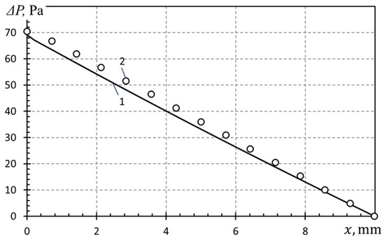
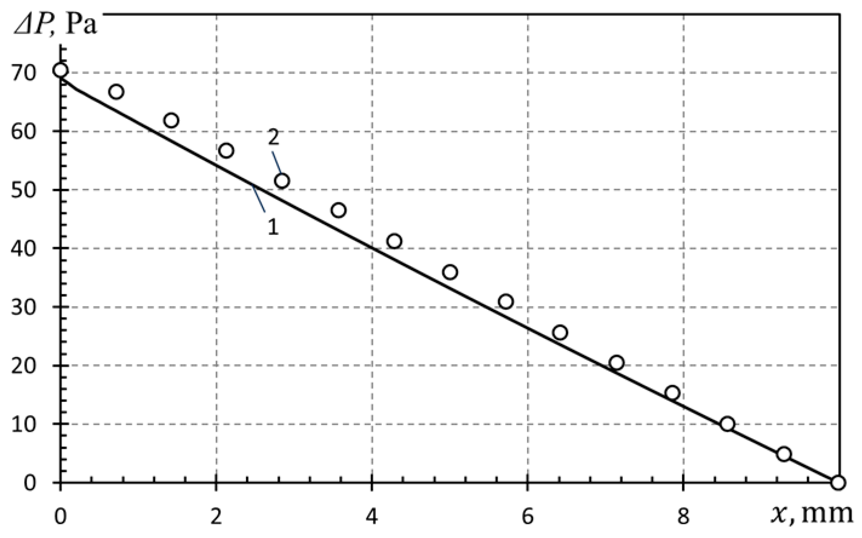
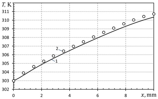
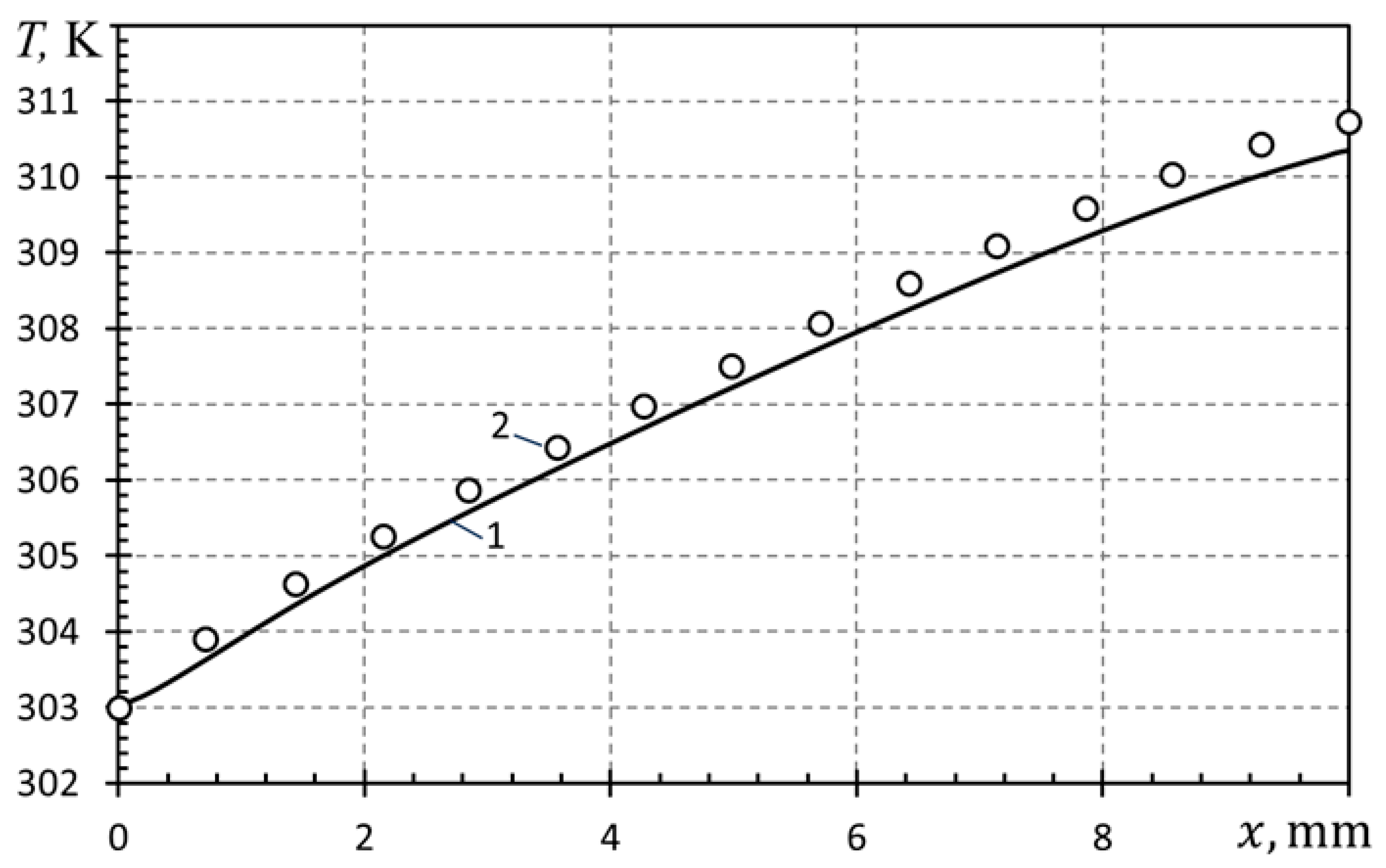
However, for the purposes of validation, the numerical results of the work [18] were used, where the object of study was a silicon water heatsink with rectangular microchannels, very close to the microchannel geometry modeled here in terms of cross-sectional dimensions, namely wch = 0.25 mm wide and hch = 1 mm high, but with a shortened length Lb = 10 mm and a base thickness of hb = 0.2 mm. This geometry was reproduced with a proportional change in the number of mesh nodes in each of its directions, after which a series of test predictions were performed corresponding to the cases most relevant to this study (Vin = 0.04 m/s—inlet velocity, 66 kW/m2—heat flux density for the bottom-heated face A1B1B2A2, K). The corresponding results for the distributions of pressure drop and temperature along the channel, presented in Figure 5 and Figure 6, respectively, demonstrate the presence of qualitative agreement (the relative error for temperature distributions T(x) does not exceed 0.11% at x = 10 mm, and for pressure drop distributions ΔP(x)—5.92% at x = 2.4 mm).
Figure 5.
Pressure drop distribution along the longitudinal axis of symmetry ΔP(x) of the tested microchannel: 1—results obtained using the model developed here, 2—data from [18].
Figure 6.
Temperature distribution along the longitudinal axis of symmetry T(x) of the tested microchannel: 1—results obtained using the model developed here, 2—data from [18].
Considering that the results of [18] have undergone comprehensive validation over a wide range of Reynolds numbers, based on microchannel length ( = 100–1000), including comparison with experimental data for shortened channels, the presented comparisons can be considered, although not complete, an encouraging verification of the constructed numerical model, which allows us to proceed to its testing on elongated microchannel heatsinks for various conditions and a discussion of the obtained results.
4. Results and Discussions
4.1. Modeling of Homogeneous Heatsink Heating
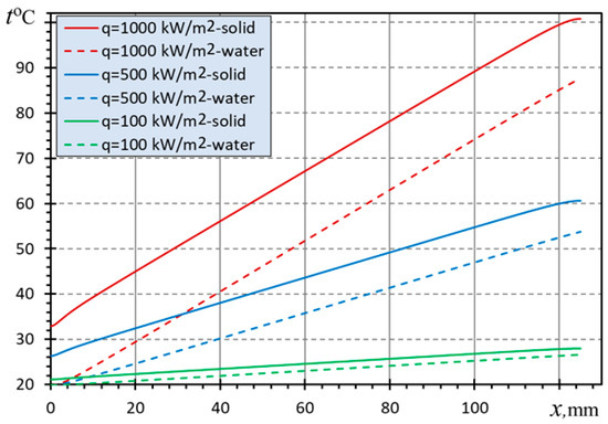
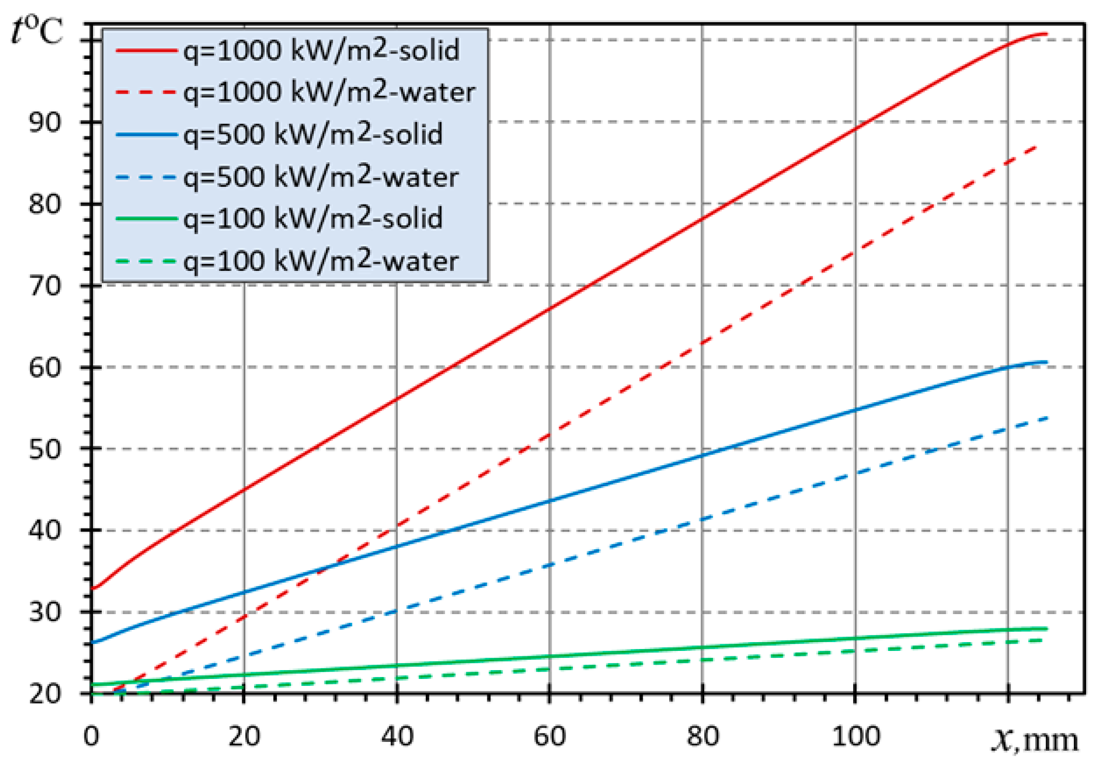
At the initial stage, parametric studies of the heatsink were carried out in a wide range of conditions (provided a homogeneous surface heat flux density along the heated base of the heatsink q = 30–2000 kW/m2 for water volume flow rates = 10–50 L/h). The results obtained demonstrate two general trends in addition to the expected improvement in heat removal as the value of rises. Firstly, the dependence of the temperature growth of both the heatsink base along the direction of flow x and for cooling water along the entire length of its base is linear. Secondly, a constant difference is maintained between the local temperature of the heatsink base and water. An example of calculations for the cases (q = 100, 500, 1000 kW/m2, = 43.2 L/h that correspond to m3/s and input mean velocity = 0.3 m/s for each microchannel of the heatsink) is presented in Figure 7.
Figure 7.
Temperature t distribution along the heatsink for various heat flux vs. x (Vin = 0.3 m/s).
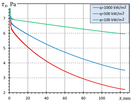
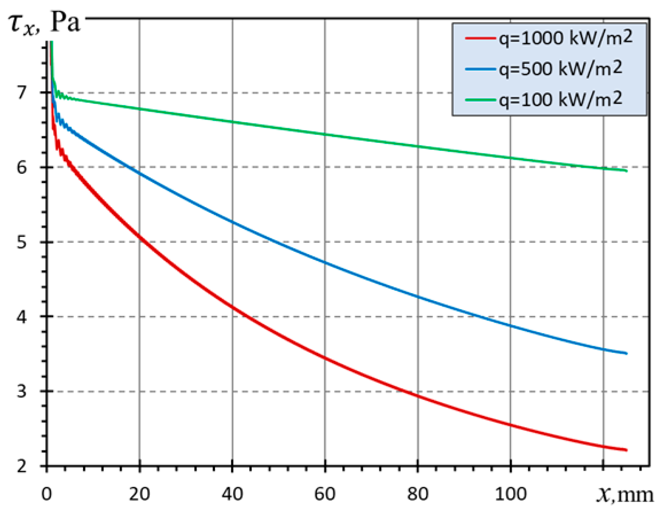
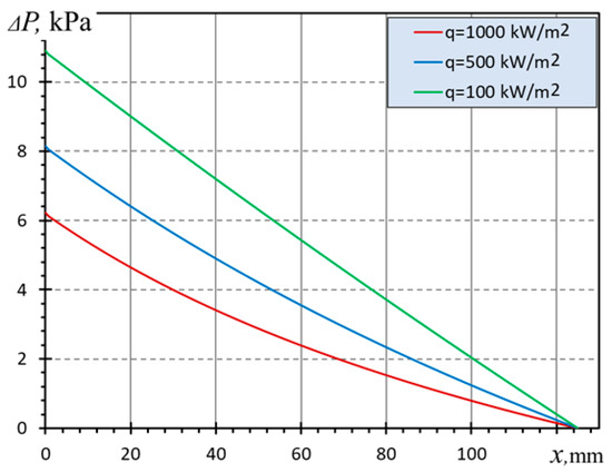
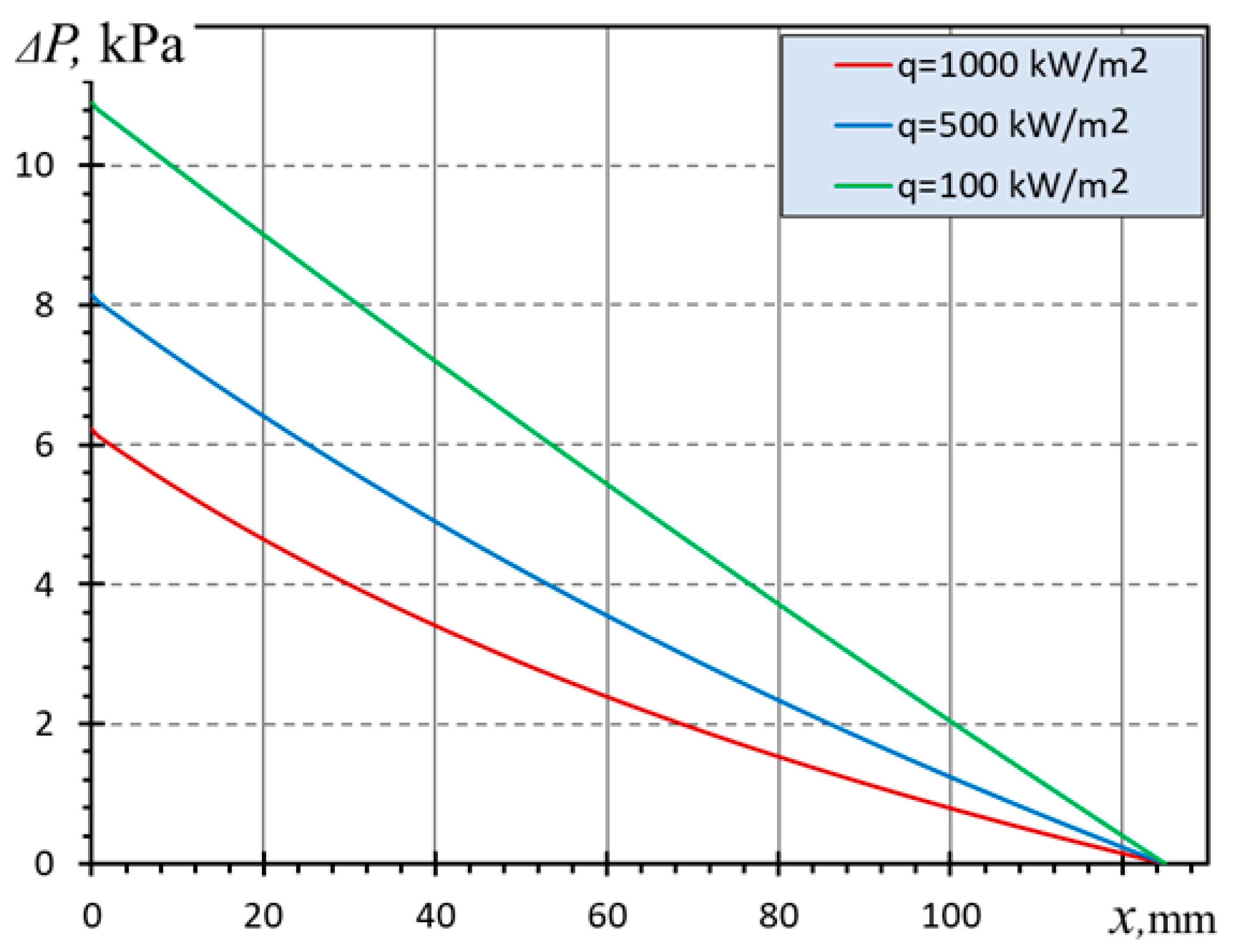
The effect of temperature changes along the direction of flow development on the physical parameters of flowing water under the abovementioned conditions is illustrated by the distributions of friction stress and pressure along the x-axis (Figure 8 and Figure 9). In the absence of such an effect, the friction stresses should be constant; however, in reality, their decrease along the length of the elongated microchannel under study is more than three times that at q = 1000 kW/m2 (Figure 8). Simultaneously, the pressure drop between the inlet and outlet sections ΔP diminished 1.83 times as the heat load on the heatsink increased from q = 100 to 1000 kW/m2 (Figure 9). Both effects are positive concomitant factors and they are primarily explained by a significant decrease in the value of as the temperature increases. In this regard, it is important to note that the presence and significance of this effect on the simulated heat removal process in the microchannel heatsink allows us to justify the need to develop numerical models even for the laminar flow mode in comparison with simpler analytical approaches which use well-known velocity profiles that are similar for all x-axis sections.
Figure 8.
Shear stress distribution along heatsink for various heat flux vs. x (Vin = 0.3 m/s).
Figure 9.
Pressure drop ΔP distribution along the heatsink for various heat flux vs. x (Vin = 0.3 m/s).
4.2. Modeling of Inhomogeneous Heatsink Heating
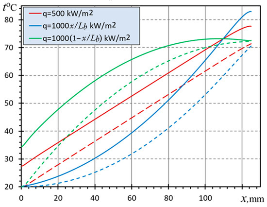
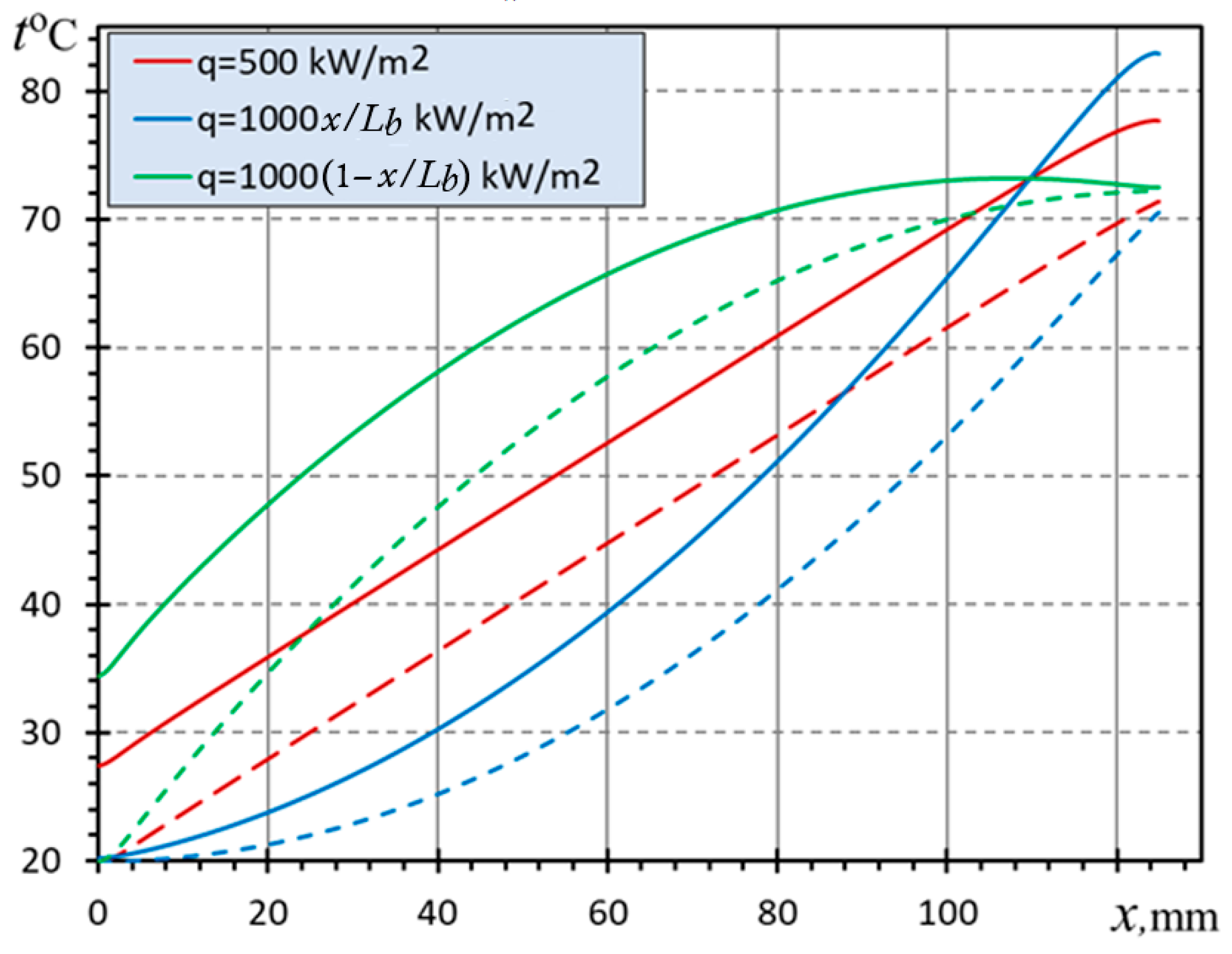
This section of the study investigates the sensitivity of the temperature distribution dependence, depending on the nature of the change in surface heat flow along the x-axis. In addition to the previously considered homogeneous heating with q = 500 kW/m2, two further cases were considered in which q increases linearly from 0 to 1000 kW/m2 or falls within the same limits. These three cases have a common property: the integral surface heat flux through the entire heated surface of the heatsink base remains constant, which allows them to be compared. As demonstrated in Figure 10, the distribution T(x) undergoes a loss of linearity during inhomogeneous heating. However, the water temperature at the end of the heatsink remains comparable regardless of the distribution q(x), indicating that water absorbs an equivalent amount of heat in all three cases examined. At the same time, from the point of view of the minimum heating of the heatsink itself, the case of a decreasing type of dependence q(x) is the most preferable, and its increase along the x-axis is the most unfavorable.
Figure 10.
Temperature t distribution (in the Celsius centigrade scale) along the heatsink for various distributions of heat flux vs. x (Vin = 0.2 m/s) in the symmetry plane of the domain. Similar to Figure 7, the solid lines correspond to the distribution of t(x) along the hottest zone of the solid heatsink base A1B1B2A2 (at y = 0), while the dashed lines illustrate the distributions of t(x) for water along the longitudinal axis of the microchannel.
The distribution of the temperature field in the vertical plane of the heatsink symmetry is found to be similar for different combinations of operating conditions. The only difference is observed in the values of the limit temperatures at the beginning and end of the heatsink. A typical example, corresponding to the case of a homogeneous distribution q = 500 kW/m2 and Vin = 0.2 m/s, is represented by Figure 11.
Figure 11.
Temperature t distribution along the heatsink in the microchannel vertical midplane: 1—copper base, 2—elongated microchannel, 3—acrylic lid.
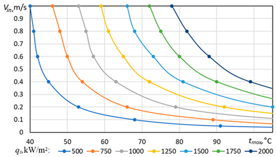
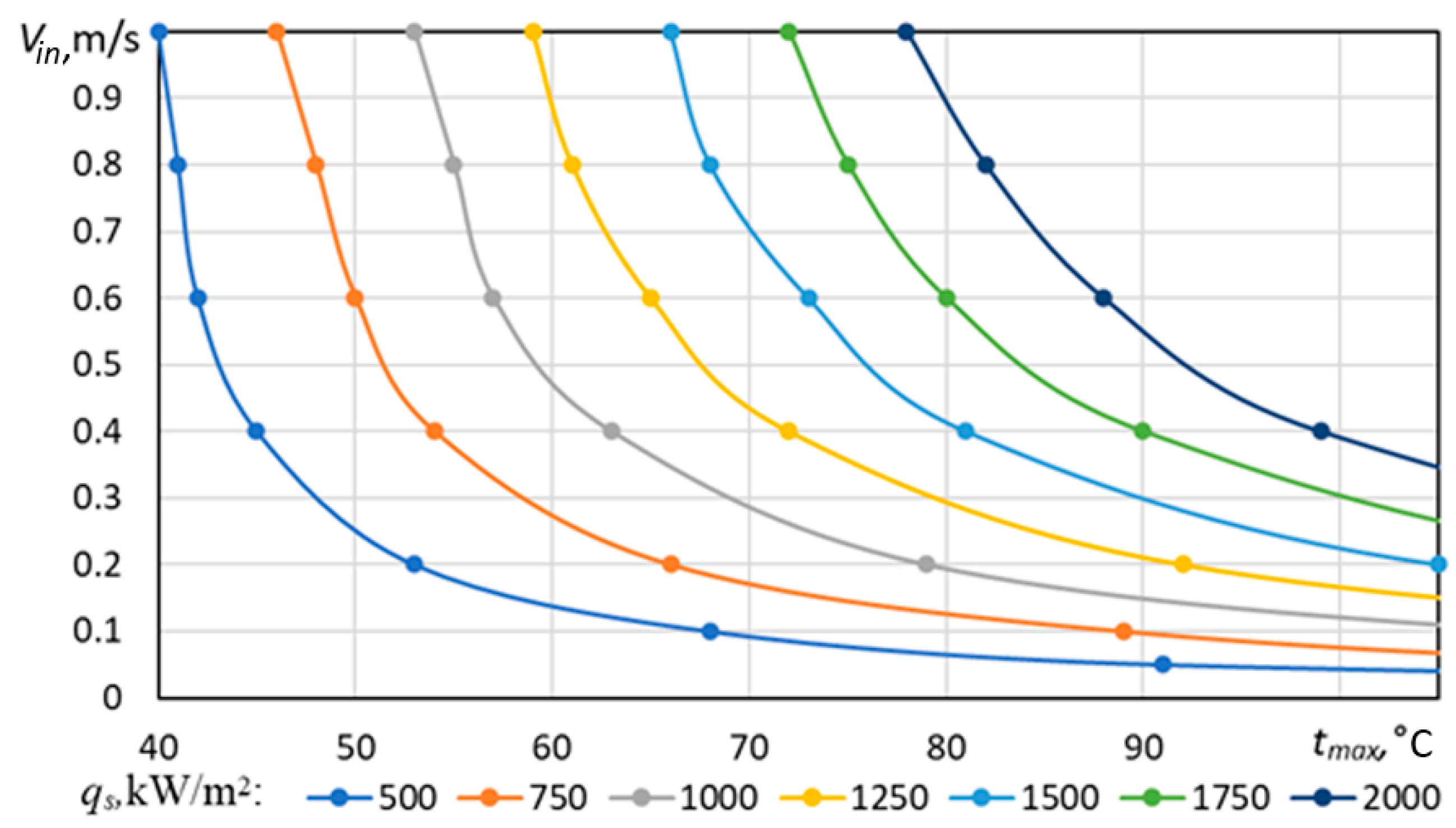
Based on the constructed mathematical model of convective heat transfer in an elongated microchannel heatsink, parametric studies of the dependence of the maximum surface heating temperature of the heatsink surface tmax on the input flow velocity were carried out for a number of values of heat flux density qs = [500, 750, 1000, 1250, 1500, 1750, 2000] kW/m2. Thereafter, a family of dependencies was constructed for each value of qs (Figure 12).
Figure 12.
Input velocity vs. maximum temperature for different heat flux density qs.
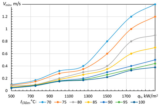
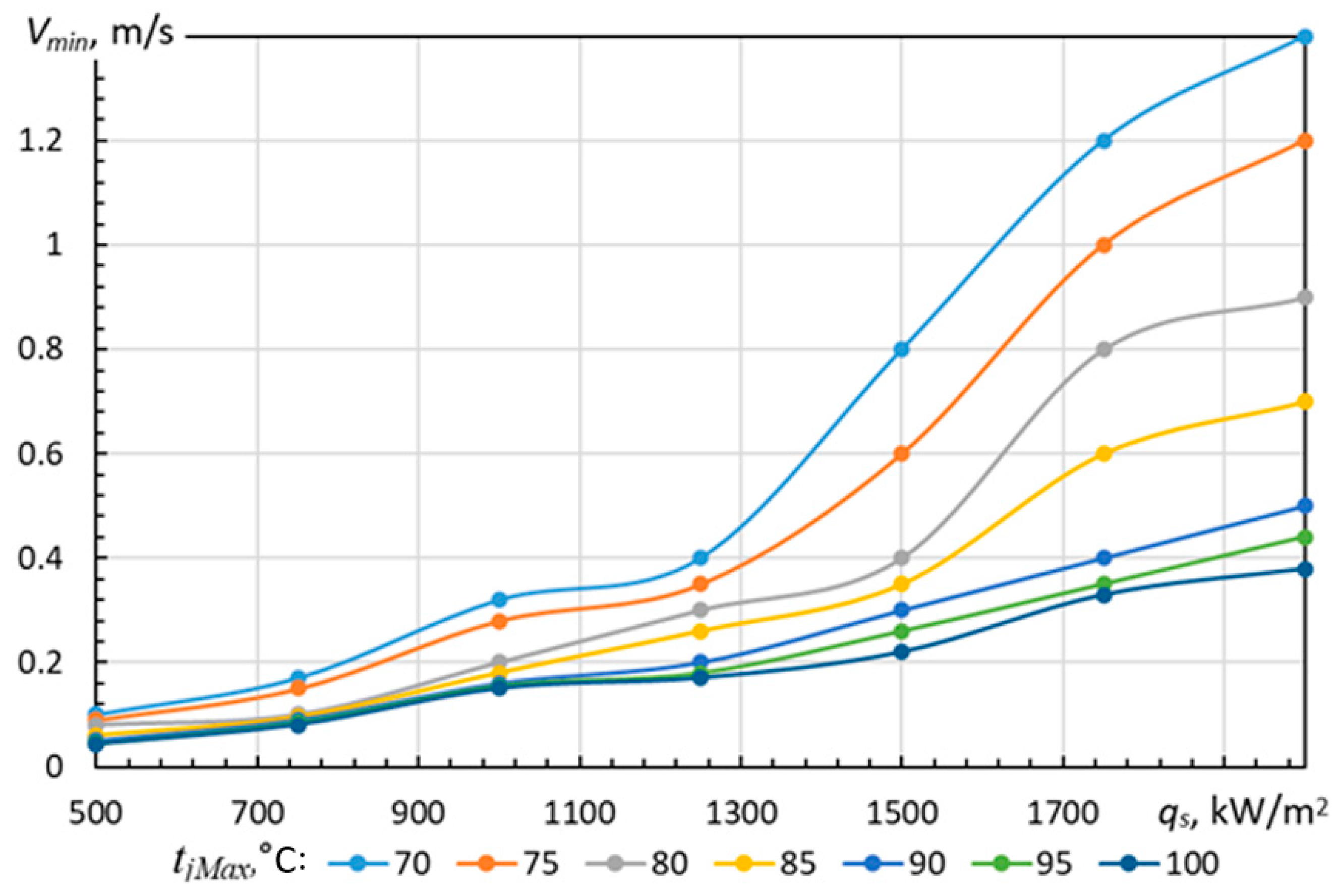
Subsequently, a series of values for the maximum temperature of the cooled microchips, referred to in the domain of electronic component operation as the maximum junction temperature tjMax, were selected. For each value of tjMax = [70, 75, 80, 85, 90, 95, 100] °C, the corresponding sets of value pairs (, qs) were determined. On the basis of the data obtained, a number of dependences Vmin(qs) were identified for tjMax = const (Figure 13).
Figure 13.
Minimum possible input velocity Vmax vs. heat flux density Vmin(qs) for different values of maximum junction temperature tjMax.
Thus, practically important information was obtained about the required minimum water flow rate through the heatsink, which guarantees the absence of overheating at any point of its lower surface in direct contact with spaced electronic components.
4.3. Modeling the Influence of the Inlet Section Location
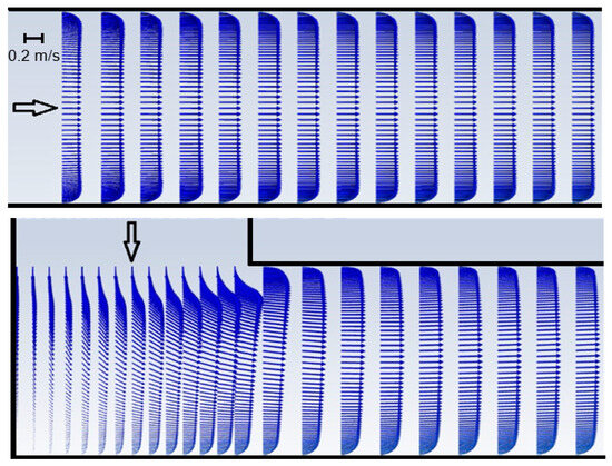
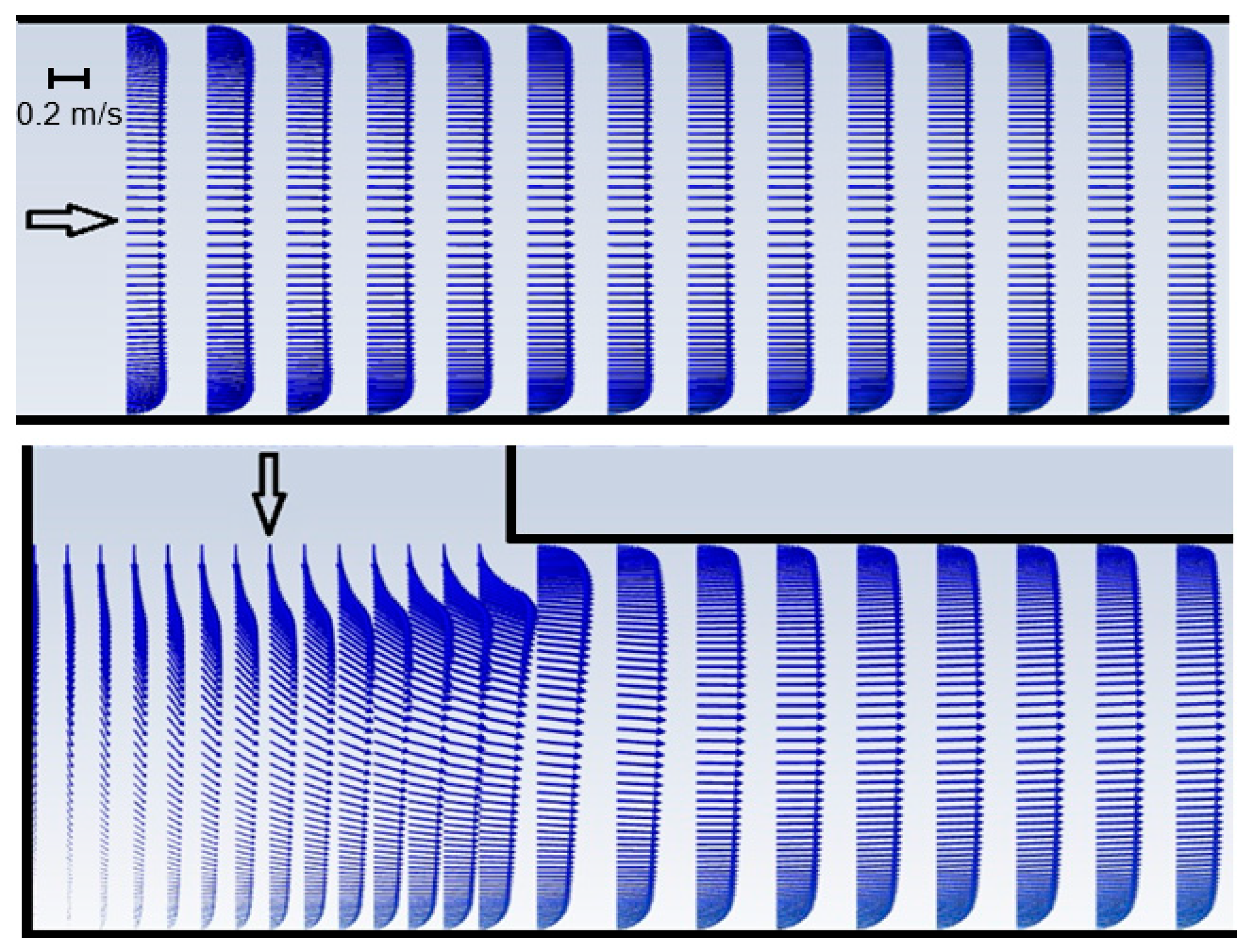
In this section, the influence of the location of the inlet section in the microchannel structure, namely horizontal and vertical, is investigated. The corresponding illustrations of the velocity field are shown in Figure 14.
Figure 14.
Velocity fields in the initial section of the microchannel for horizontal (top) and vertical (bottom) placement of the inlet. The inlet velocity in both cases is m/s.
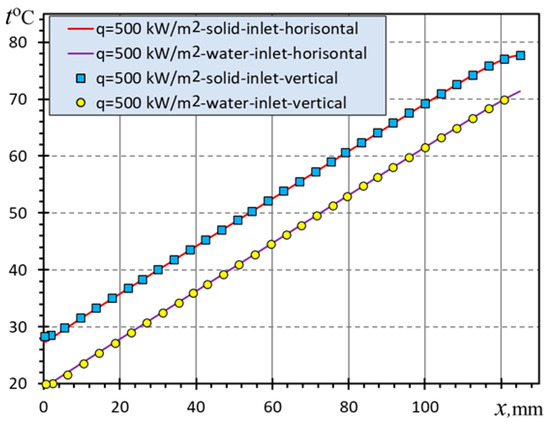
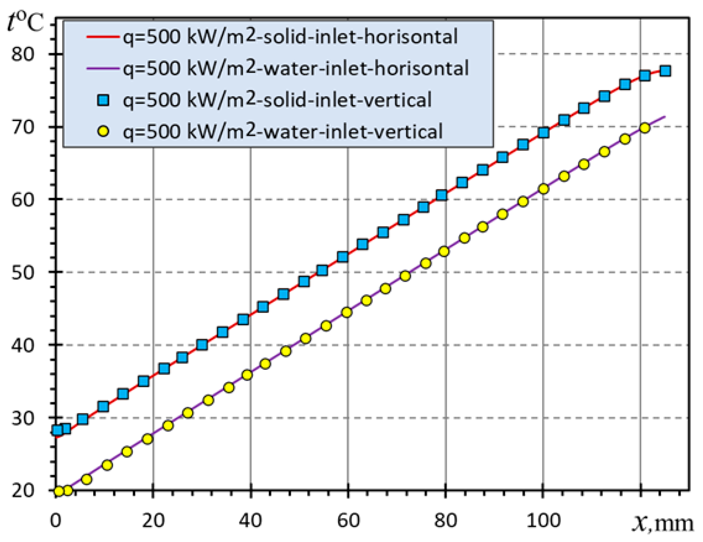
In accordance with the above distributions of velocity fields (Figure 15), the microchannel structure, characterized by its high internal resistance, exhibits a comparable behavior in both cases. This similarity is evident from a length of approximately one and a half to two heights of the microchannel hch from the beginning of the flow formation, where the velocity profiles for both inlets become almost similar in shape. The results of modeling the temperature distribution for both cases (Figure 15) also demonstrate the insensitivity of the microchannel efficiency to the location of the input section.
Figure 15.
Temperature distribution along the heatsink t(x) with horizontal and vertical inlet section.
It can thus be concluded that the location of the inlet for the microchannel heatsink is of negligible importance in terms of influencing the efficiency of hydrodynamics and heat transfer in the microchannel. Therefore, it can be designed in any convenient way.
5. Conclusions
On the basis of the research undertaken, a numerical model of the flow in a heatsink with an elongated microchannel structure and both horizontal and vertical inlet sections was developed and tested. The results of the testing allowed the following conclusions to be formulated:
- Based on the numerical experiment performed, it was found that a significant change in the viscosity of water (approximately 2.5 times) with an increase in temperature to 75–80 °C practically does not affect the heat exchange properties of the microchannel heatsink. However, it significantly (up to 41%) reduces the overcoming friction and, as a result, reduces the pressure drop along the microchannel.
- Despite the highly elongated continuous channel (Lb/wch = 625, hch/wch = 12.5), the efficiency of heat transfer between the water coolant and the heated heatsink base still does not degrade. In the case of a homogeneous heat flux along the heatsink base, the temperature difference between them remains constant along the entire heatsink length, and the dependence T(x) remains linear almost up to the outlet (Figure 4).
- For the microchannel structure studied, it was found that due to its high dissipation, the method of liquid supply (horizontally or vertically oriented inlet) practically does not affect the efficiency of heat transfer; therefore, from the standpoint of rational design, it can be assumed that the most rational location of the vertical inlet jet is in the middle of the channel length, which will ensure the formation of a further symmetrical flow along opposite parts of the microchannel structure relative to the inlet location, providing better uniformity of cooling of an elongated array of electronic components.
- The developed numerical model can be useful and expedient in the process of designing new samples of elongated microchannel heat exchangers in order to determine their rational geometry and expected efficiency.
Author Contributions
Conceptualization, Y.S.; methodology, Y.S.; software, Y.S.; validation, Y.S.; formal analysis, Y.S. and A.K.; investigation, Y.S. and A.K.; resources, Y.S. and A.K.; data curation, Y.S. and A.K.; writing—original draft preparation, Y.S.; writing—A.K.; visualization, Y.S.; supervision, Y.S.; project administration, A.K. All authors have read and agreed to the published version of the manuscript.
Funding
This research received no external funding.
Data Availability Statement
The data presented in this study are available on reasonable request from the first author.
Conflicts of Interest
The authors declare no conflicts of interest.
References
- Ghani, U.; Wazir, M.A.; Akhtar, K.; Wajib, M.; Shaukat, S. Microchannel Heat Sinks—A Comprehensive Review. Electron. Mater. 2024, 5, 249–292. [Google Scholar] [CrossRef] [Scilit]
- Rahman, M.A.; Hasnain, S.M.M.; Paramasivam, P.; Ayanie, A.G. Advancing thermal management in electronics: A review of innovative heat sink designs and optimization techniques. RSC Adv. 2024, 14, 31291–31319. [Google Scholar] [CrossRef] [Scilit] [PubMed]
- Elsherbiny, M.S.; Ali, M.; Shahin, M.; El-Kady, M. A Review of miniature channels and nanofluids technologies used as heat transfer enhancement techniques for microcooling systems. J. Al-Azhar Univ. Eng. Sect. 2024, 19, 185–211. [Google Scholar] [CrossRef] [Scilit]
- Bhandari, P.; Rawat, K.S.; Prajapati, Y.K.; Padalia, D.; Ranakoti, L.; Singh, T. A review on design alteration in microchannel heat sink for augmented thermohydraulic performance. Ain Shams Eng. J. 2024, 15, 102417. [Google Scholar] [CrossRef] [Scilit]
- Dwivedi, A.; Khan, M.M.; Pali, H.S. A comprehensive review of thermal enhancement techniques in microchannel heat exchangers and heat sinks. J. Therm. Anal. Calorim. 2023, 148, 13189–13231. [Google Scholar] [CrossRef] [Scilit]
- Zhou, J.; Cao, X.; Zhang, N.; Yuan, Y.; Zhao, X.; Hardy, D. Micro-Channel Heat Sink: A Review. J. Therm. Sci. 2020, 29, 1431–1462. [Google Scholar] [CrossRef] [Scilit]
- Chen, N.; Chen, Y.; Zhao, H. Study of Two-Phase Microchannel Heat Sink Fabricated by A.M. Technology for Energy Reuse in the Electronic Device. Green Energy Environ. Technol. 2022, 2022, 1–19. [Google Scholar] [CrossRef] [Scilit]
- Sharma, J.P.; Sharma, A.; Jilte, R.D.; Kumar, R.; Ahmadi, M.H. A Study on Thermohydraulic Characteristics of Fluid Flow Through Microchannels. J. Therm. Anal. Calorim. 2020, 140, 1–32. [Google Scholar] [CrossRef] [Scilit]
- Yuan, Y.; Chen, L.; Yang, Q.; Ke, H.; Gu, L.; Tao, W.-Q. Multi-Fidelity Topology Optimization of Flow Boiling Heat Transfer in Microchannels. Int. J. Heat Mass Transf. 2025, 239, 126585. [Google Scholar] [CrossRef] [Scilit]
- Wu, Z.; Xiao, W.; He, H.; Wang, W.; Song, B. Jet-Enhanced Manifold Microchannels for Cooling Electronics up to a Heat Flux of 3000 W Cm−2. Nat. Electron. 2025, 8, 810–817. [Google Scholar] [CrossRef] [Scilit]
- Kamal, H.; Dewan, A. Analysis of Interrupted Rectangular Microchannel Heat Sink with High Aspect Ratio. J. Appl. Fluid Mech. 2017, 10, 117–126. [Google Scholar] [CrossRef] [Scilit]
- Rawat, D.S.; Lodhi, M.S.; Sheorey, T. Experimental Investigation of Active Microfluidic Cooling Solution to Processor Chip. J. Appl. Fluid Mech. 2025, 18, 145–158. [Google Scholar] [CrossRef] [Scilit]
- Gupta, S.; Subbarao, P.M.V. Experimental investigation of conjugate heat transfer in nanofluid-cooled microchannel heat sink to mitigate back axial conduction at low Reynolds numbers. J. Therm. Anal. Calorim. 2025, 150, 5751–5774. [Google Scholar] [CrossRef] [Scilit]
- Gao, Q.; Zou, H.; Li, J. Numerical Investigations of Heat Transfer and Fluid Flow Characteristics in Microchannels with Bionic Fish-Shaped Ribs. Processes 2023, 11, 1861. [Google Scholar] [CrossRef] [Scilit]
- Li, W.; Ma, Y.; Zhang, X.; Zhao, J. Review of bionic study on enhanced microchannel heat transfer by passive methods. Renew. Sustain. Energy Rev. 2025, 222, 115926. [Google Scholar] [CrossRef] [Scilit]
- Du, J.; Fang, Y. Bioinspired spider-web microchannel with five-input-four-output manifold: Enhanced thermal performance for 10,000 kW/m2 chip-scale embedded cooling. Int. J. Heat Fluid Flow 2025, 114, 109794. [Google Scholar] [CrossRef] [Scilit]
- The Modelica Buildings Library. Available online: https://simulationresearch.lbl.gov/modelica/releases/v5.0.0/help/Buildings_Media_Specialized_Water_TemperatureDependentDensity.html#Buildings.Media.Specialized.Water.TemperatureDependentDensity (accessed on 15 May 2026).
- Mat, M.N.H.; Radzie, N.R.N.; Saidur, R. Thermohydraulic performance of MXene-based nanofluid in a microchannel heat sink: Effect of volume fraction. J. Therm. Anal. Calorim. 2024, 149, 9791–9803. [Google Scholar] [CrossRef] [Scilit]


Disclaimer/Publisher’s Note: The statements, opinions and data contained in all publications are solely those of the individual author(s) and contributor(s) and not of MDPI and/or the editor(s). MDPI and/or the editor(s) disclaim responsibility for any injury to people or property resulting from any ideas, methods, instructions or products referred to in the content. |
© 2026 by the authors. Published by MDPI on behalf of the Nanjing University of Aeronautics and Astronautics. Licensee MDPI, Basel, Switzerland. This article is an open access article distributed under the terms and conditions of the Creative Commons Attribution (CC BY) license.