


Abstract
The influences of the shape of the leading edge of the upstream plate on the transition region from steady laminar flow to unsteady flow, as well as the heat transfer from these leading edges, were numerically studied. The calculations were performed using the finite volume method in two-dimensional domains in a low Reynolds number regime with a constant incoming flow. The results show that von Kármán vortex shedding patterns start behind the rounded upstream plate at a low Reynolds number of 114. When the leading edge of the upstream plate is square, the plate experiences flow separation and the flow become unsteady at higher Reynolds numbers of around 400. The mean Nusselt number of the upstream plate increases by approximately 179% and 213% for square and rounded leading edges, respectively, for Reynolds numbers ranging from 100 to 700.
1. Introduction
Compact heat exchangers are used in various applications, including radiator and air conditioners, as well as for cooling electronic devices. This type of heat exchanger is designed with flat plate segments arranged in the flow direction to enhance thermal performance at low Reynolds numbers [1]. The rate of heat transfer of a compact heat exchanger can also be improved using surface interruption, which resets the boundary layer growth at each corner of the leading edge of plate [2,3]. A number of studies have been conducted to explore various methods for improving the characteristics of separated and reattached flow over a blunt flat plate [4,5,6,7,8]. Ota et al. [9,10,11] pioneered this field by studying the flow characteristics of separation, reattachment, and rate of heat transfer under high Reynolds numbers on a blunt flat plate while also examining the effects of the nose shape of the plate on flow and heat transfer rates. It is important to note that the separation, recirculation, and reattachment feature of the flow is frequently an unfavorable result of the surface interruption, causing the friction factor to increase more than the Nusselt number [12]. The sharp corner of the plate caused separation flow at the leading edge [13], resulting in separation bubbles with no heat transfer benefit [14,15]. Flow separation and heat transfer behavior are two fluid flow problems that have attracted research attention because they occur frequently in various engineering applications, including electronics heat sinks, chips on a board, blades, wings, sails, and buildings [16,17]. Notably, these applications each have a different shape, which complicates their analysis. Yanaoka et al. [18] used two-dimensional (2D) and three-dimensional (3D) numerical simulations to investigate the flow and heat transfer characteristics over a blunt flat plate placed inside a square channel in a laminar uniform flow. Their 2D and 3D analyses showed that the transition from steady to unsteady flow occurs at different Reynolds numbers, with the 3D analysis occurring at a lower Reynolds number. Chatterjee et al. [19] conducted a numerical investigation of the effect of the shape of the curved and flat surfaces of a semicircular cylinder on the unsteady flow and heat transfer characteristics observed in laminar flow. They concluded that the shape surface facing the flow affects both the heat transfer rate and the frequency of vortex shedding. Chatterjee and Mondal [20] subsequently studied the unsteady mixed convective heat transfer characteristics of two square cylinders arranged in tandem in a laminar flow condition and revealed that the Nusselt number increased with the Reynolds number and the Richardson number, while the Richardson number also influenced the drag and lift coefficients. Chatterjee and Chaitanya [21] analyzed flow and heat transfer in tandem circular cylinders rotating at Re=100, comparing the impact of different spacings using two-dimensional numerical simulations. They discovered that cylinder spacing impacts the critical rotation rate. Regardless of gap spacing, isothermal and vortices behave in unstable ways when there is no rotation. Increasing the cylinder’s rotational speed also results in a reduction in heat transfer. Chaitanya and Chatterjee [22] conducted further research on tandem circular cylinders by rotating the upstream and downstream cylinders in opposite directions at Re=100. They found that counterrotation stabilizes the flow field around the cylinders, which changes the characteristics of fluid flow and heat transfer. Chaitanya et al. [23] investigated the effect of cross-thermal buoyancy on flow transitions around side-by-side cylinders at Reynolds numbers ranging from 10 to 40. They found that heat transfer from both cylinders increases as the Reynolds number increases. Dey and Das [24] studied the flow around a triangular solid (thorn) fixed to a square cylinder and observed that the thorn length and inclination angle affected the drag and lift coefficients. A numerical study by Rastan et al. [25] on vortex shedding from a bluff body with cross-sections ranging from square to normal flat plates revealed significant effects on the critical Reynolds number of vortex shedding due to the cross-sectional aspect ratio of the bluff body. As a result, the separation of the flow above the plate must be taken into consideration when designing the surface of the plate. Laminar boundary layer separation caused by the square leading edge of a plate is common in many forms of compact heat exchangers; however, when the leading edge of an upstream plate is rounded, the extent to which the flow and heat transfer mechanisms are similar, including throughout the transition process from steady to unsteady flow, remains unclear. The aim of this study was to numerically study the flow behavior and heat transfer characteristics of two flat plates, one in which the upstream plate lacked sharp edges and the other in which the upstream plate had a square leading edge. The conditions for the onset of the transition from steady to unsteady laminar flow regime between a pair of flat plates were investigated. Additionally, the behavior of the flowing and the Nusselt number was studied under the laminar flow regime. In this numerical analysis, the distance between the plates is fixed as S/L = 2.36. Air is used as working fluid with a Prandtl number of 6.14, and a uniform flow with a Reynolds number ranging from 100 to 700 is used. The results of this study should contribute to a better of flow behavior and heat transfer rates through interrupted plates and offer increased clarity regarding significant edge effects.
2. Computational method
2.1. Computational domain
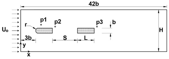
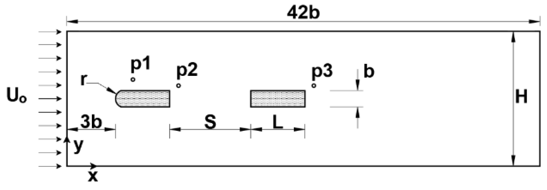
The physical problem considers two plates of equal length and thickness (length L, and thickness b) in a uniform flow of velocity Uo and temperature To. The two plates are arranged in configuration on the central axis of a computational domain as shown in Figure 1. The blockage ratio of 2D computational domain of the problem was defined by Br (%) = b/H, where H is the distance between the upper and lower boundaries and b is the plate thickness. A blockage ratio (Br) of 4.2% was used in the computations. The domain consisted of an upstream plate located 3b away from the inlet boundary; the total domain length, at which the flow was fully developed, was 42b. The spacing between the two plates was a constant value of S/L=2.36. The flat plates were designed with a thickness, b, of 3.2 mm and a length, L, of 12.7 mm. The upstream plates had the same length and thickness but two different shapes; one had a rounded leading edge with a radius of 1.2 mm, and the other had a square leading edge. Table 1 shows the geometrical details of two different leading edges used in the study, whose plate dimensions are in accordance with the experimental study conducted by Roadman et al. [26].
Figure 1.
Flow configuration and computational domain.
Table 1.
Geometric and flow parameters.
2.2. Governing equations
The flow in this study was assumed to be a 2D, incompressible, and unsteady laminar flow. The viscosity, density, and thermal properties of the fluid remained constant.
Furthermore, viscous dissipation was neglected. As a result of these assumptions, numerical simulations were carried out by solving time-dependent, continuity, momentum, and energy equations. The governing equations were as follows [27,28,29]:
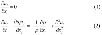

Where i, j = 1–3; x1, x2 and x3 represent the streamwise, cross-stream, and spanwise directions, respectively. u1, u2 and u3 represent the corresponding resolved velocity components [30]. While ρ, ν and α are density, kinematic viscosity, and thermal diffusivity, respectively.
2.3. Boundary conditions
The governing equations of (1)–(3) were solved in the computational domain shown in Figure 1 using Fluent CFD software. Boundary conditions play an important role in the analysis and were categorized as follows:
Inlet: uniform flow (u=Uo, v=0 and T=To)
Outlet: Assuming the flow parameter did not vary in the x-direction.
Plate: Constant heat flux for energy; no-slip velocity conditions were imposed.
Upper and lower ends: Periodic boundary conditions is given by [31]
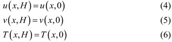 The air was used as working fluid with the Prandtl number Pr = ν/α remained constant at 6.14.
2.4. Numerical methods and description of the simulations
The simulations were carried out on a staggered grid using the commercial CFD software Fluent, which utilizes the finite volume method. The second upwind differencing scheme (USD-2) was used to discretize the convective and diffusive terms. The SIMPLE algorithm was used to find the solution, and the second-order implicit solution method was used to confirm calculation accuracy. The numerical simulations were carried out at Reynolds numbers ranging from 100 to 700 corresponding with the laminar flow. A convergence criterion was set to less than 10-6. Table 1 shows the examined simulation cases.
2.5. Data acquisition
The Reynolds number, based on plate thickness, was calculated by:

where b is the thickness of the plate.
The time-averaged local Nusselt number was expressed as:
 where is the time-averaged local heat transfer coefficient.
The mean Nusselt number was expressed as:

2.6. Mesh design and independence tests
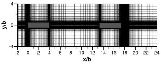
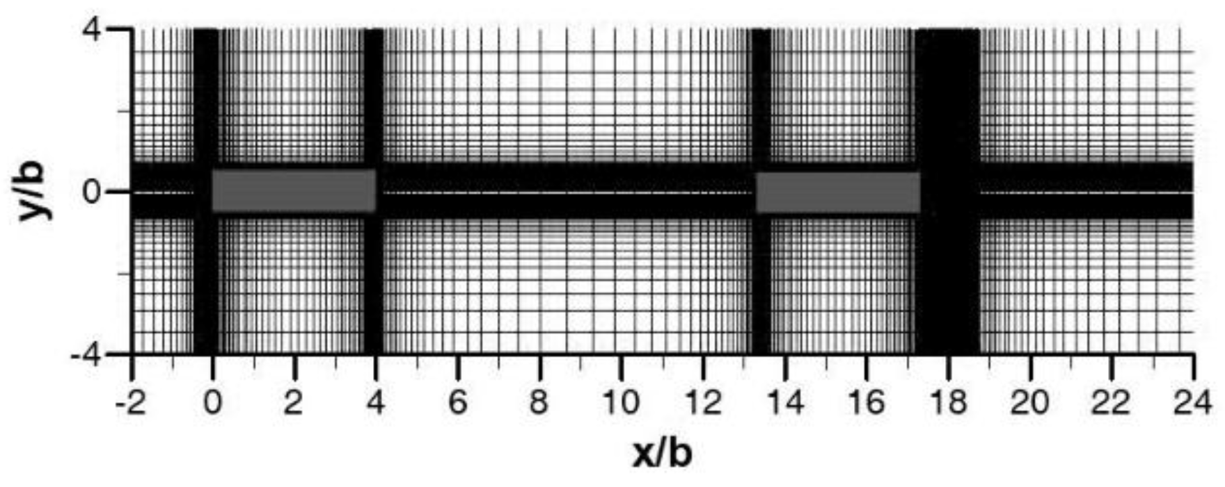
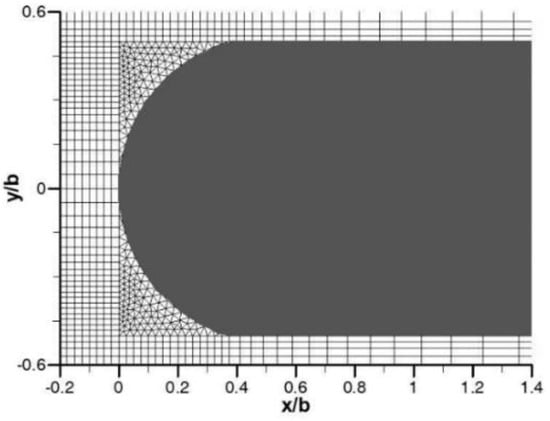
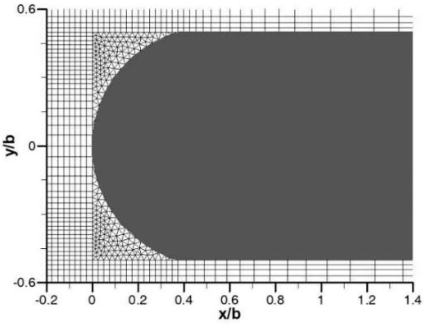
This study employed non-uniform mesh distributions in the x and y directions, as shown in Figure 2. The meshes were refined around the leading edge of each plate; i.e., they were refined around areas with high gradients. Conversely, a less refined mesh was used in areas with low gradients. A triangular mesh was formed around the upstream edge of the rounded plate, as shown in Figure 3, while a rectangular mesh was used for the upstream plate with the square leading edge, as shown in Figure 2. In this study, four different grids were used to study the effect of grid density on the calculation results for the mean Nusselt number of an upstream plate, as shown in Table 2. A grid independence test was performed for a Reynolds number of 793 (based on the plate length). The results show that the mean Nusselt number of the square and round leading edges was sensitive to the grid size. However, the deviations of the mean Nusselt number between the grids of case 3 and case 4 for both the square leading edge and the round leading edge were only 0.492% and 0.315%, respectively.
Figure 2.
Non-uniform computational mesh around two plates.
Figure 3.
Enlarged view of the mesh around the rounded leading edge.
Table 2.
Grid independence tests.
Thus, a total of 31,086 and 29,842 nodes were used for square and rounded leading edges, respectively, in the computational domain to simulate the study of flow and heat transfer. In addition, independent grid validation results showed that using these non-uniform grid structures for calculations was reliable and reduced computation time for consumers.
2.7. Validation
The numerical method described above was validated using the well-known theoretical correlation for laminar flow over a flat plate as shown in Eq. (10). This correlation was used to calculate the mean Nusselt number for fluid flow along a horizontal flat plate at a constant surface temperature, given by [32].

Equation (10) is applicable for ReL < 5 × 10⁵, Pr > 0.6.
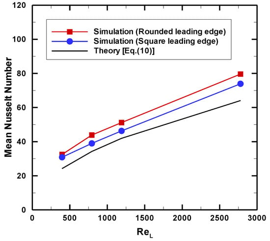
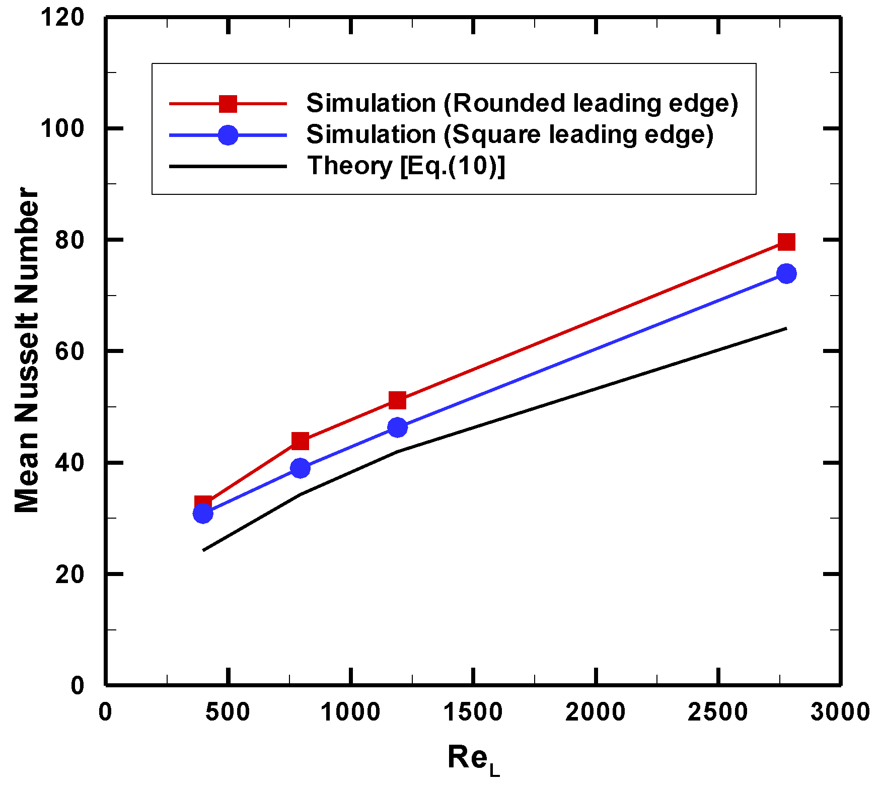
The average Nusselt number, based on the plate length, was calculated using a non-uniform grid distribution of case 3 (Table 2) that had been independence-grid checked. Figure 4 shows a comparison of the mean Nusselt numbers in the upstream plates versus the Reynolds counts for both the numerical results from the present study and the theoretical correlation results for square-edged and rounded leading edges. The results showed that the numerical simulation results clearly followed the same trend as the theoretical results, with good agreement between the theoretical and simulation results of a flat plate with a square leading-edge nose. For the simulation results of a square leading edge, the maximum deviation was about 6.857%. Nevertheless, for the simulation results of a rounded leading edge, the maximum deviation was about 8.533%. This deviation difference can be explained by the numerical diffusion of the solver or vortex, as well as the flow separation at the leading edge.
Figure 4.
Comparison between theory and numerical simulations of single plate.
3. Results and discussion
3.1. Effect of Reynolds number on flow over the two plates in a channel
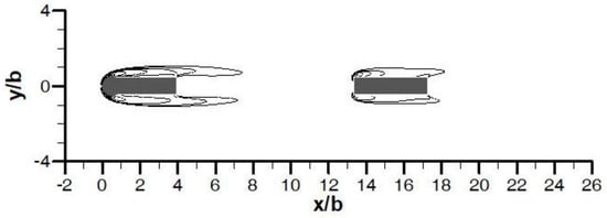
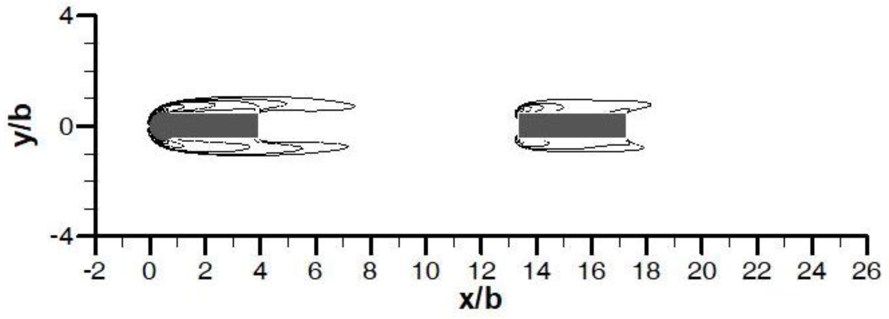
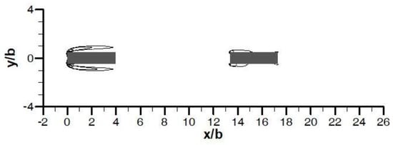
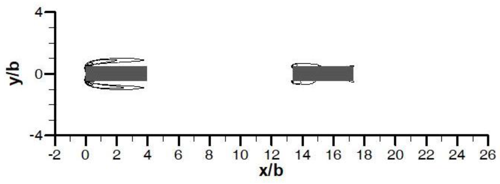
At a low Reynolds number of about 100, flow separation and vortex shedding around plates did not occur on either the rounded or square-edged simulations, as illustrated in Figure 5. The flow characteristic remained almost steady; the influence of the viscous forces was greater than that of the inertial forces.
Figure 5.
Instantaneous vorticity contours for a flow past the rounded leading-edge plate at Reb=100.
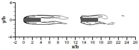
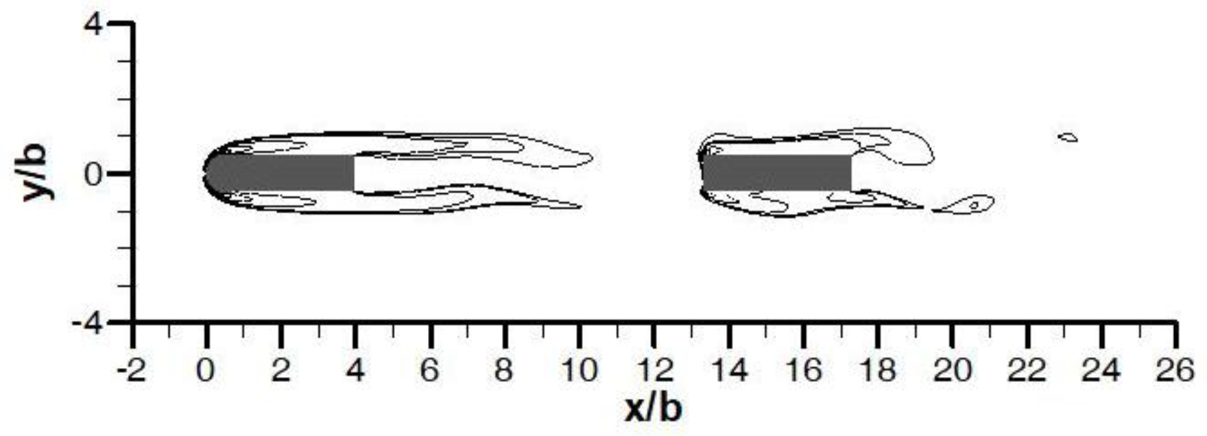
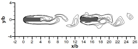
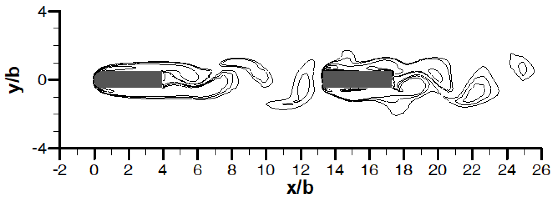
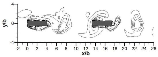
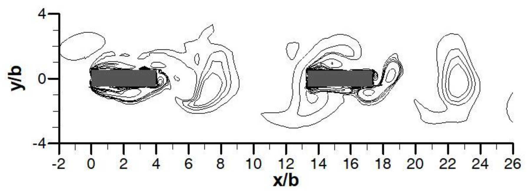
Figure 6 shows a Reynolds number of 114 over the plates with a rounded leading edge; the flow’s behavior became unsteady. More specifically, the vortices were formed behind the downstream plate; they then periodically separated from either side, forming a von Kármán vortex street. Thus, the critical of transition from a steady to an unsteady flow is approximately Reynolds number 114 for a flow over an upstream plate with rounded edges under inline flow for S/L=2.36 and L/b=3.96. These results are in agreement with the flow visualization results obtained by Roadman et al. [26]. With further increases of the Reynolds number from the critical of 114 to around 200, the flow over the rounded upstream plate became unsteady, vortices elongated, and some even shed in the direction of the flow, as shown in Figure 7. Conversely, at a Reynolds number of 200 on a square leading edge, no vortices were generated, as shown in Figure 8. However, the results of calculations using a Reynolds number of 400 showed that the flow eventually became unsteady and that vortex shedding around the plate appeared.
Figure 6.
Instantaneous vorticity contours for a flow past the rounded leading-edge plate at Reb=114.
Figure 7.
Instantaneous vorticity behind the rounded leading-edge plate in a channel at Reb= 200.
Figure 8.
Instantaneous vorticity contours for a flow past the square leading-edge plate at Reb=200.
The results of calculations for the rounded and square edged plates at the same Reynolds number showed that the rounded edge obstructed flow and flow separation, reattachment length founded on an upstream plate's top and bottom surfaces, while the square edged plate allowed for the easy occurrence of flow separation and reattachment; this is because the square-edged plated has sharp corners and the flow cannot turn, as shown in Figure 9.
Figure 9.
Instantaneous vorticity behind the square leading-edge plate in a channel at Reb= 700.
For the flow behavior of interrupted flat plates when the upstream plate is rounded, the calculation showed that the vortices migrate to the back of the plate. The flow separation between top and bottom surface of plate reformed at the back of each plate, resulting in Kelvin-Helmholtz flow type instability, as shown in Figure 7, which is similar to flowing through an airfoil.
3.2. Frequency analysis
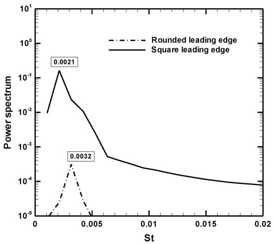
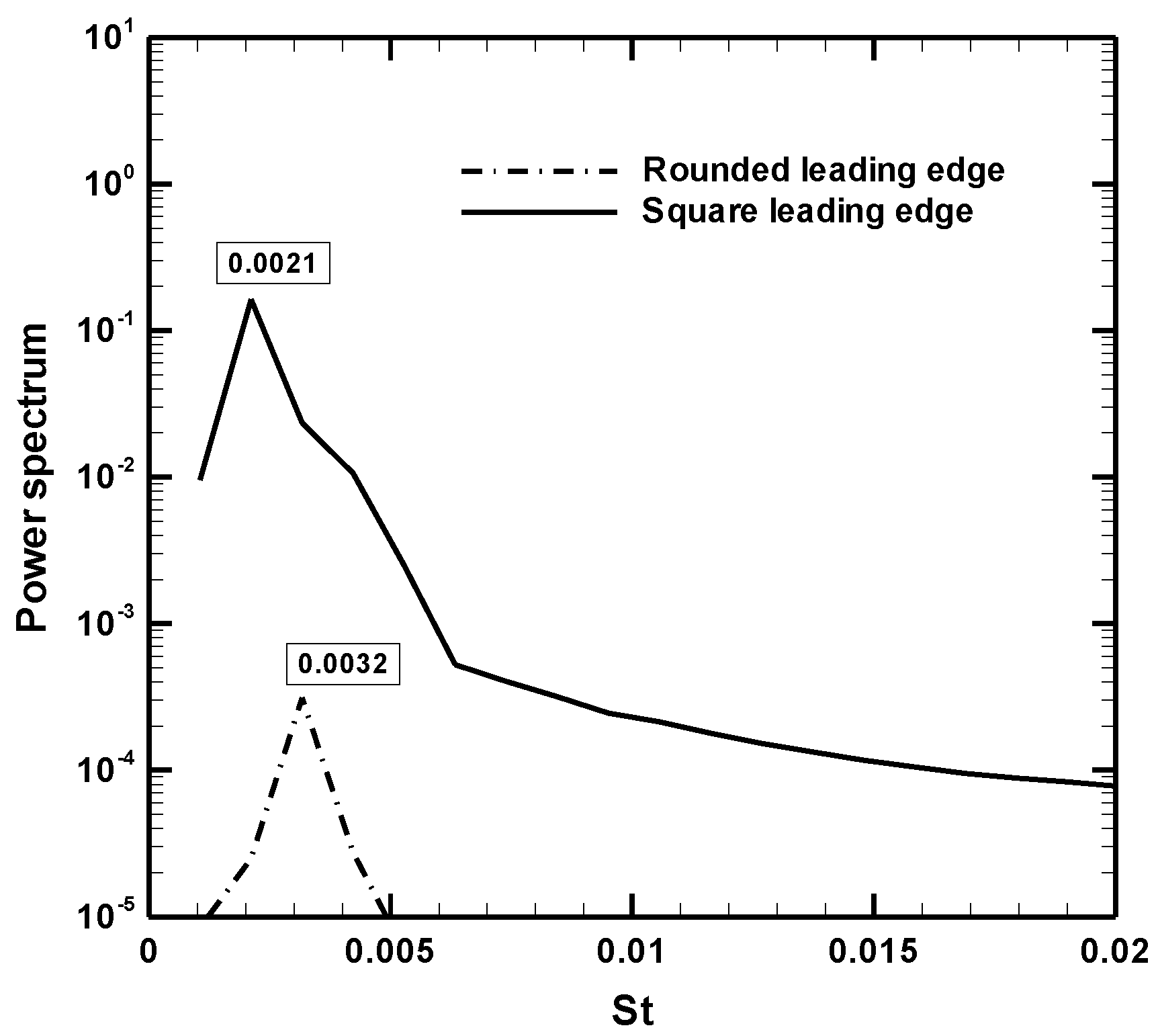
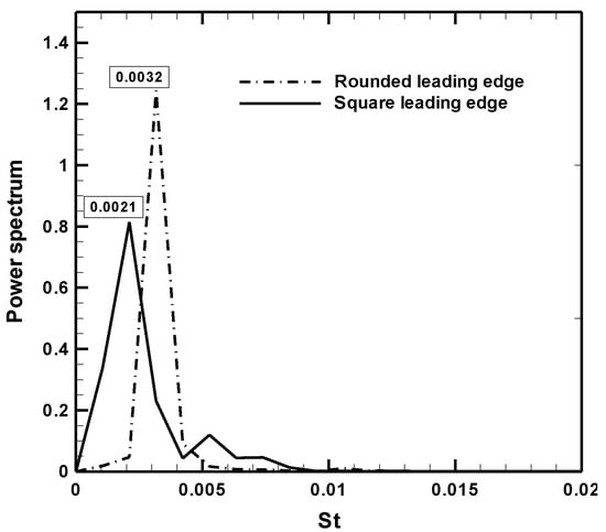
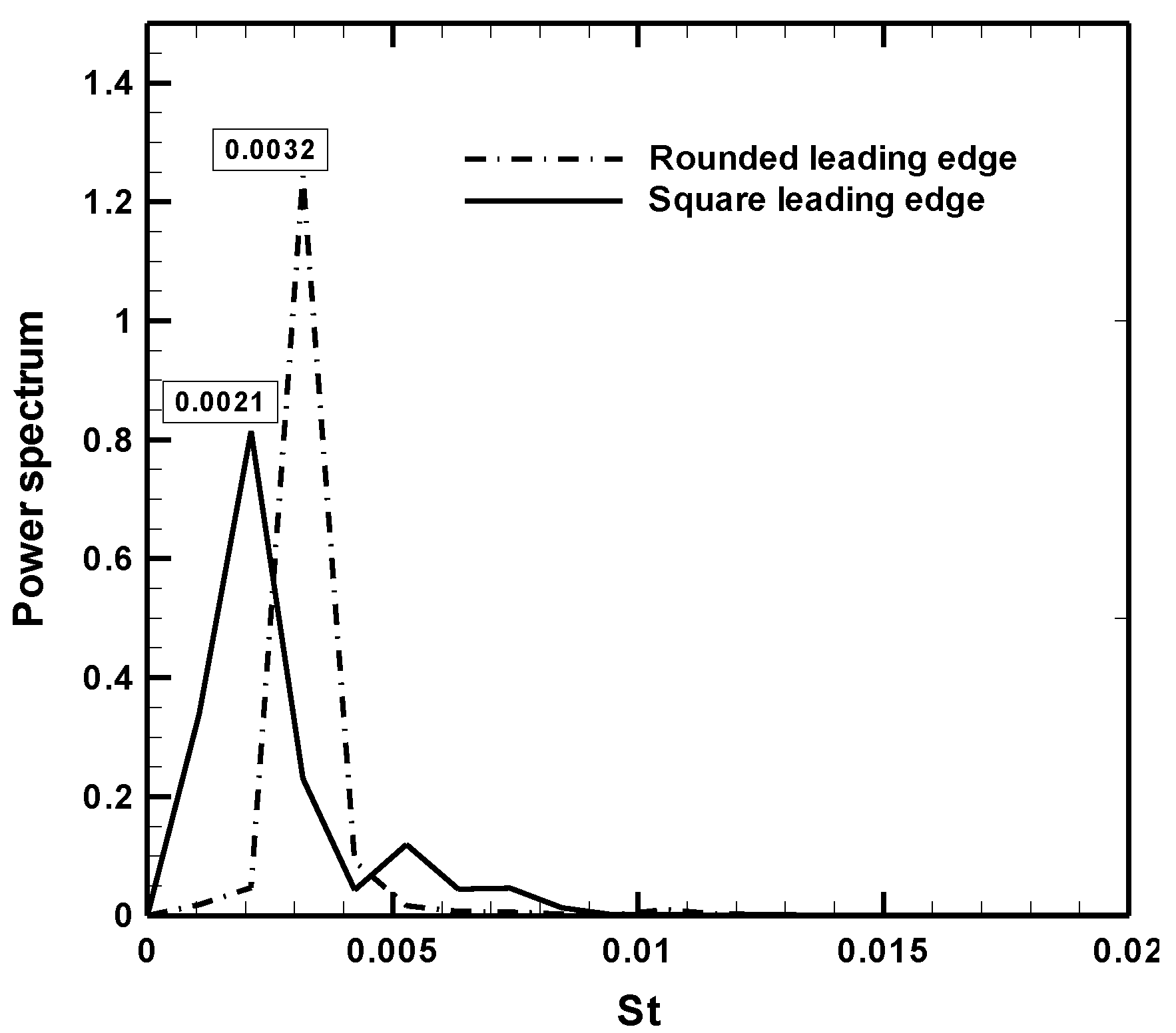
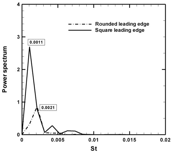
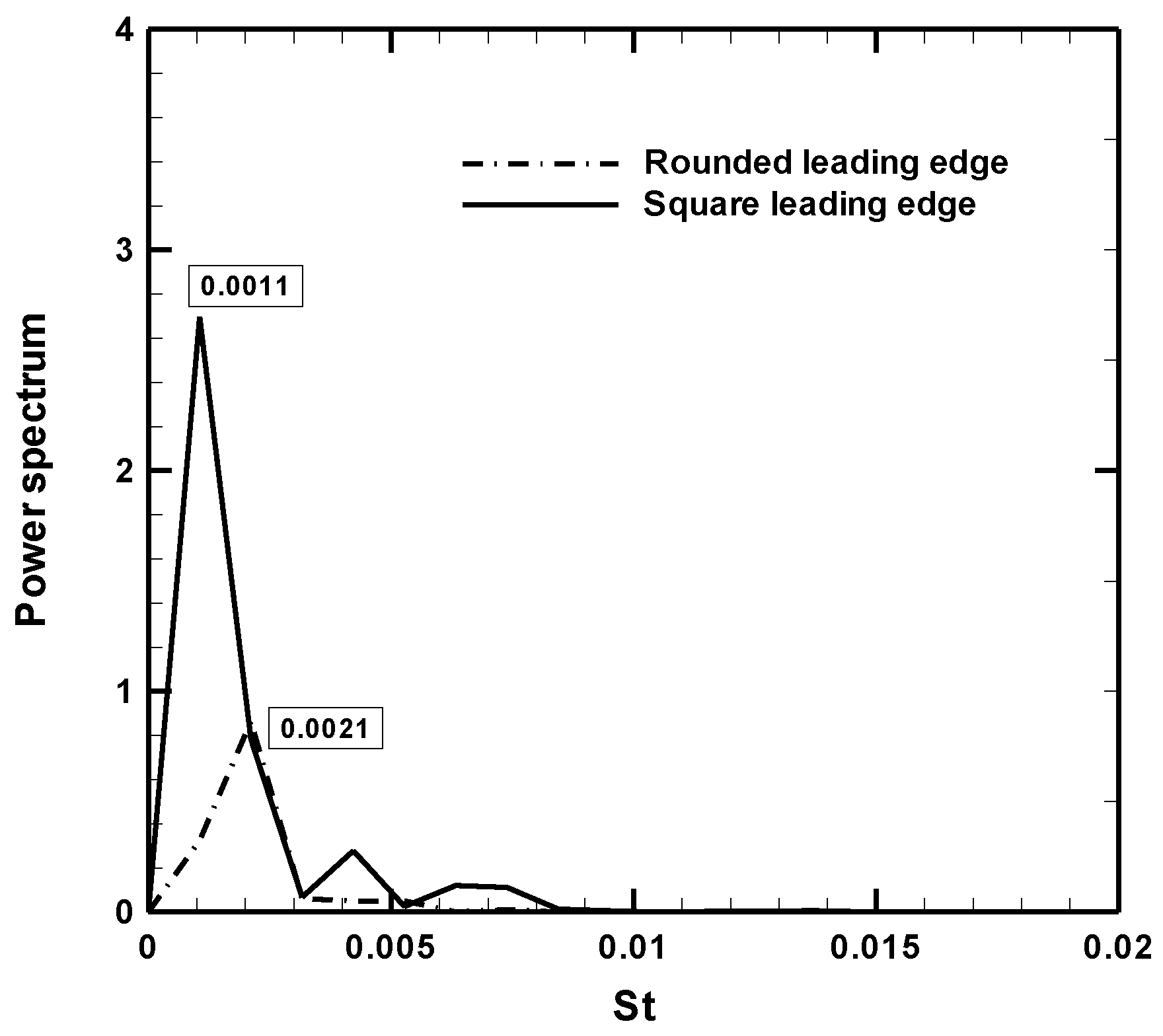
Figure 10, Figure 11 and Figure 12 show the power spectrum density obtained using Fast Fourier Transform analysis (FFT) on velocity data according to the recorded position of p1 (for x=0.945b, y=1.0b), p2 (for x=2.34b, y=0.5b), and p3 (for x=2.34b, y=0.5b); these positions are shown in Figure 1. The dimensionless frequency, defined as the Strouhal number of vortex shedding, was expressed as:
Figure 10.
The Strouhal number of the location of p1 at Reb=700.
Figure 11.
The Strouhal number of the location of p2 at Reb=700.
Figure 12.
The Strouhal number of the location of p3 at Reb=700.
 where f is the frequency of vortex shedding in the plates.
The highest peaks in each power spectrum graph correspond to the vortex shedding frequency. First, at p1's location, which is near the top surface of the upstream plate, under Reynolds number of 700, the results show that the Strouhal number peaked at approximately 0.0021 for a square-edged plate and 0.0032 for a rounded edge plate, as shown in Figure 10. This result clearly shows that a square upstream plate leads to a more unstable flow than the rounded plate, which created a small flow separation.
Figure 11 illustrates the power spectrum density at p2; it can be seen that a square-edged upstream plate has a power spectrum density peak at a Strouhal number of around 0.0021 which is the same as p1; however, the power spectrum density is lower. When the upstream plate is rounded, the power spectrum density is highest at a Strouhal number of 0.0032; power spectrum density was also greater than at p1.
Figure 12 shows the power spectrum density and Strouhal number at p3 behind of a downstream plate. The power spectrum density is highest at the Strouhal number of 0.0011 and 0.0021 for the square and rounded edges, respectively. The calculations show that flowing over a rounded-edged plate creates a stronger von Kármán vortex street behind the plate than flowing over a square leading edge.
3.3. Heat transfer
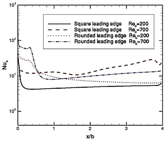
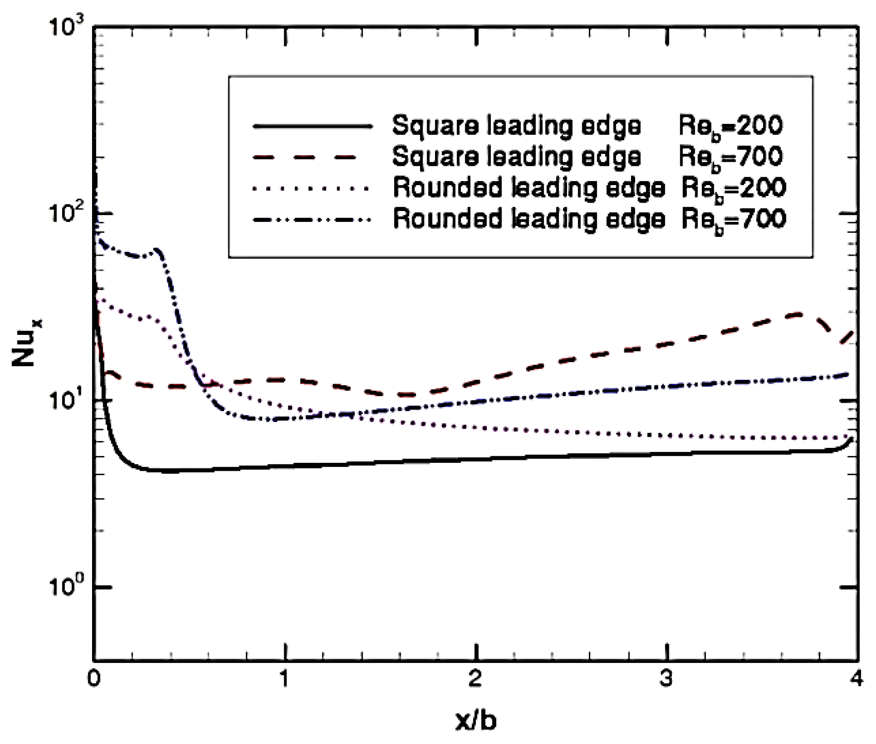
In this study, the specified heat flux along the plate surface remained constant so that as the temperature of the plate wall decreased, both the heat transfer rate and the local heat transfer coefficient increased. Figure 13 shows the distribution of the local time-averaged Nusselt number along the surface of the upper plate for different Reynolds numbers. As shown in this graph, the Nusselt number sharply increased at each Reynolds number due to the strong shear layer near the leading edge of the plate. The peak Nusselt number neighborhood of the leading edge is due to the flow separations occurring there; however, the local Nusselt number decreased continuously as distance increased, and then slightly increased again at the end edge of each plate due to the instability mechanisms of the free shear layers downstream of the plate.
Figure 13.
Effect of leading edges on Nusselt number distributions on the upstream plate.
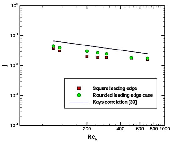
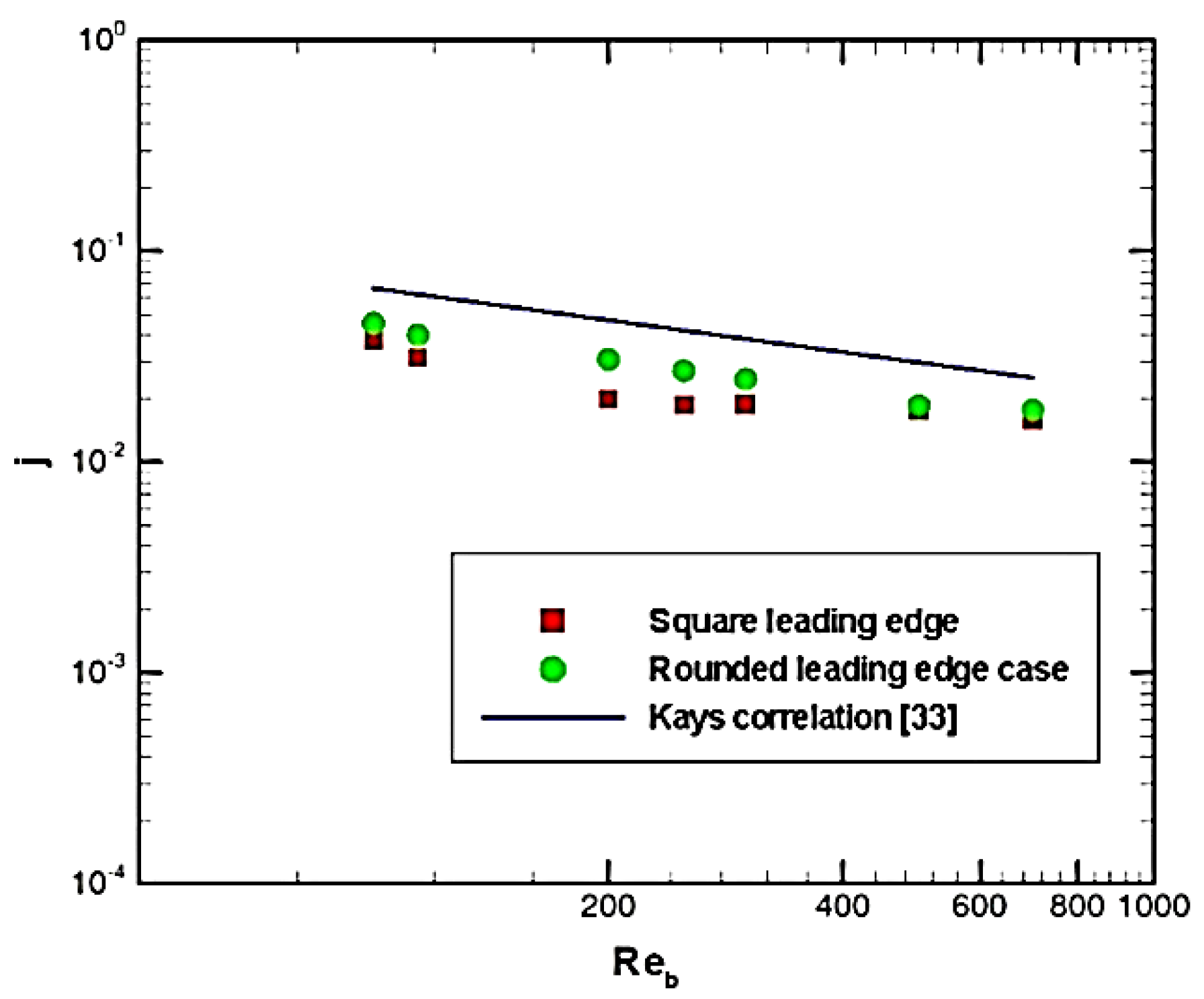
The total averaged Nusselt number, which is expressed in terms of the dimensionless Colburn j factor, is a calculation of the average heat transfer over the upper and lower surfaces of the upstream plate, as shown in Figure 14.
Figure 14.
Variations of the Colburn j-factor with the Reynolds number.
The Colburn j factor is defined as:

The calculated results are compared to the correlation by Kays, which is expressed in Eq. (13) (see Manglik et al.[33]) for laminar flow over interrupted plates:

The results indicated that increases in the Reynolds number caused a decrease in the j factor, which is in line with the results of Eq. (13) and is caused by a decrease in the Stanton numbers (St=Nu/RePr). According to the calculations, increasing the Reynolds number from 100 to 700 increases the mean Nusselt number of the upstream plate by approximately 179% and 213% for square and rounded leading edges, respectively.
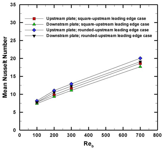
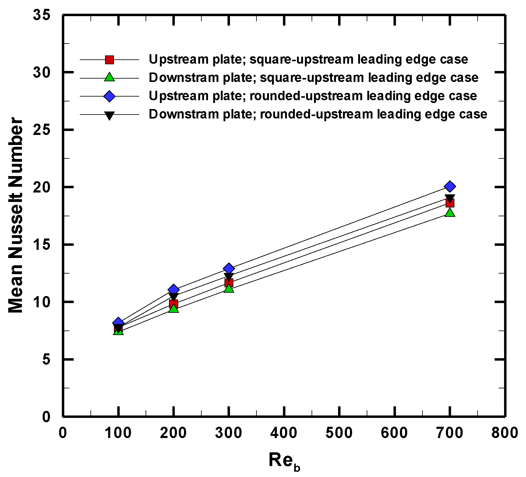
Figure 15 illustrates the mean Nusselt number of the upstream and downstream plates in the flow direction. The results showed that the shape of the upstream plate had little effect on the downstream plate, possibly due to the spacing of the two plates used for simulation.
Figure 15.
The Nusselt number of upstream and downstream plates with the Reynolds number.
4. Conclusions
The flow behavior and heat transfer for two different plates with constant spacing along the flow direction were numerically investigated. This study focused on the effects of the upstream plate’s leading edges, whether square or rounded, on the transition region from steady laminar flow to unsteady flow, as well as heat transfer from these leading edges. Two-dimensional simulations were performed using a low Reynolds number regime with a constant incoming flow. The calculations revealed a difference in the transition from steady to unsteady flow between the square and round leading edges. When the upstream plate was rounded, the transition from steady to unsteady flow occurred at a low Reynolds number of around 114, and von Kármán vortex shedding occurred near the back of the plate. However, no periodic vortex shedding was observed at those Reynolds numbers in the case of the square leading edge. As the Reynolds number approached 400, flow separation occurred at the leading edge of the square upstream plate, leading to unsteady flow. The results of the Strouhal number calculations showed that the upstream plate’s square and rounded leading edges differed and that the flow was more unstable along the square leading edge than along the rounded leading edge. As the Reynolds number increased from 100 to 700, the mean Nusselt number of the upstream plate increased by approximately 179% and 213% for the square and rounded leading edges, respectively. However, further study is needed on lift coefficient signals during vortex shedding for a clearer understanding of interrupted flat plate flow transitions.
Acknowledgments
The author would like to thank Agricultural engineering department, Rajamangala University of Technology Thanyaburi, Thailand for their equipment support for this study.
Nomenclature
| b | plate thickness, m | S/L | dimensionless spacing between plates |
| Br | blockage ratio, Br = b/H | T | temperature, K |
| f | frequency of vortex shedding, Hz | U | inlet flow velocity, m/s |
| h | heat transfer coefficient, W/m2 K | x | coordinate, distance from the leading edge |
| H | height of the domain, m | of the plate, m | |
| j | Colburn factor | y | coordinate, m |
| k | thermal conductivity, W/m K | Greek symbols | |
| L | plat length, m | ρ | density, kg/m3 |
| L/b | dimensionless plate length | α | thermal diffusivity, m2/s |
| L/r | dimensionless plate radius | ν | kinematic viscosity, m2/s |
| Nu | Nusselt number | Subscripts | |
| Pr | Prandtl number | o | inlet |
| r | radius, m | b | plate thickness |
| Re | Reynolds number, Re = Ub/ν | i | velocity components |
| St | Strouhal number | x | local value |
| S | plate spacing | mean | mean value |
References
- Marty, P.; Michel, F.; Tochon, P. Experimental and numerical study of the heat transfer along a blunt flat plate. Int. J. Heat Mass Transf. 2008, 51, 13–23. [Google Scholar] [CrossRef] [Scilit]
- Mullisen, R.S.; Loehrke, R.I. A study of the flow mechanisms responsible for heat transfer enhancement in interrupted-plate heat exchangers. J. Heat Transf. 1986, 108, 377–385. [Google Scholar] [CrossRef] [Scilit]
- Chakma, J.M.; Abedin, M.Z. Review on heat transfer enhancement by rectangular Fin. Int. J. Eng. Mater. Manuf. 2021, 6. [Google Scholar] [CrossRef] [Scilit]
- Lane, J.C.; Loehrke, R.I. Leading edge separation from a blunt plate at low Reynolds number. J. Fluids Eng. 1980, 102, 494–496. [Google Scholar] [CrossRef] [Scilit]
- Zelenka, R.L.; Loehrke, R.I. Heat transfer from interrupted plates. J. Heat Transf. 1983, 105, 172–177. [Google Scholar] [CrossRef] [Scilit]
- Nakamura, Y.; Ohya, Y.; Ozono, S.; Nakayama, R. Experimental and numerical analysis of vortex shedding from elongated rectangular cylinders at low Reynolds numbers 200-103. J. Wind. Eng. Ind. Aerodyn. 1996, 65, 301–308. [Google Scholar] [CrossRef] [Scilit]
- Chai, L.; Xia, G.D.; Wang, H.S. Laminar flow and heat transfer characteristics of interrupted microchannel heat sink with ribs in the transverse microchambers. Int. J. Therm. 2016, 110, 1–11. [Google Scholar] [CrossRef] [Scilit]
- Yifan, D.; Chuangxin, H.; Peng, W.; Yingzheng, L. Unsteady behaviors of separated flow over a finite blunt plate at different inclination angles. Phys. Fluids 2020, 32, 035111–035111. [Google Scholar] [CrossRef] [Scilit]
- Ota, T.; Kon, N. Heat transfer in the separated and reattached flow on a blunt flat plate. J. Heat Transf. 1974, 96, 459–462. [Google Scholar] [CrossRef] [Scilit]
- Ota, T.; Kon, N. Heat transfer in the separated and reattached flow over blunt flat plates —Effects of nose shape. Int. J. Heat Mass Transf. 1979, 22, 197–206. [Google Scholar] [CrossRef] [Scilit]
- Ota, T.; Asano, Y.; Okawa, J.-i. Reattachment length and transition of the separated flow over blunt flat plates. Bulletin JSME 1981, 24, 941–947. [Google Scholar] [CrossRef] [Scilit]
- Shah, R.K.; Sekuli, D.P. Fundamentals of Heat Exchanger Design; John Wiley & Sons, Inc.: Hoboken, NJ, USA, 2003. [Google Scholar]
- Fujiwara, K.; Sriram, R.; Kontis, K. Experimental investigations on the sharp leading-edge separation over a flat plate at zero incidence using particle image velocimetry. Exp. Fluids 2020, 61, 205–205. [Google Scholar] [CrossRef] [Scilit]
- N. Forced laminar convection in an array of stacked plates. Numer. Heat Transf. Part A Appl. 1994, 25, 393–408. [Google Scholar] [CrossRef] [Scilit]
- Suksangpanomrung, A.; Djilali, N.; Moinat, P. Large-eddy simulation of separated flow over a bluff rectangular plate. Int. J. Heat Fluid Flow 2000, 21, 655–663. [Google Scholar] [CrossRef] [Scilit]
- Yaghoubi, M.; Mahmoodi, S. Experimental study of turbulent separated and reattached flow over a finite blunt plate. Exp. Therm. Fluid Sci. 2004, 29, 105–112. [Google Scholar] [CrossRef] [Scilit]
- Smith, J.A.; Pisetta, G.; Viola, I.M. The scales of the leading-edge separation bubble. Phys. Fluids 2021, 33, 045101. [Google Scholar] [CrossRef] [Scilit]
- Yanaoka, H.; Yoshikawa, H.; Ota, T. Numerical simulation of laminar flow and heat transfer over a blunt flat plate in square channel. J. Heat Transf. 2001, 124, 8–16. [Google Scholar] [CrossRef] [Scilit]
- Chatterjee, D.; Mondal, B.; Halder, P. Unsteady forced convection heat transfer over a semicircular cylinder at low Reynolds numbers. Numer. Heat Transf. Part A Appl. 2013, 63, 411–429. [Google Scholar] [CrossRef] [Scilit]
- Chatterjee, D.; Mondal, B. Unsteady mixed convection heat transfer from tandem square cylinders in cross flow at low Reynolds numbers. Heat Mass Transf. 2013, 49, 907–920. [Google Scholar] [CrossRef] [Scilit]
- Chatterjee, D.; Chaitanya, N.V.V.K. Convective transport around two rotating tandem circular cylinders at low Reynolds numbers. Sādhanā 2020, 45, 107. [Google Scholar] [CrossRef] [Scilit]
- Chaitanya, N.V.V.K.; Chatterjee, D. Influence of counter rotation on fluid flow and heat transfer around tandem circular cylinders at low Reynolds number. J. Braz. Soc. Mech. Sci. Eng. 2021, 43, 357. [Google Scholar] [CrossRef] [Scilit]
- Chaitanya, N.V.V.K.; Chatterjee, D.; Mondal, B. The role of cross thermal buoyancy on flow transition around side-by-side cylinders at low Reynolds numbers. J. Therm. Anal. Calorim. 2023, 148, 2921–2931. [Google Scholar] [CrossRef] [Scilit]
- Dey, P.; Das, A.K. Numerical analysis of drag and lift reduction of square cylinder. Eng. Sci. Technol. Int. J. 2015, 18, 758–768. [Google Scholar] [CrossRef] [Scilit]
- Rastan, M.R.; Alam, M.M.; Zhu, H.; Ji, C. Onset of vortex shedding from a bluff body modified from square cylinder to normal flat plate. Ocean. Eng. 2022, 244, 110393. [Google Scholar] [CrossRef] [Scilit]
- Roadman, R.E.; Loehrke, R.I. Low Reynolds number flow between interrupted flat plates. J. Heat Transf. 1983, 105, 166–171. [Google Scholar] [CrossRef] [Scilit]
- Suksangpanomrung, A.; Chungpaibulpatana, S.; Promvonge, P. Numerical investigation of heat transfer in pulsating flows through a bluff plate. Int. Commun. Heat Mass Transf. 2007, 34, 829–837. [Google Scholar] [CrossRef] [Scilit]
- Zhou, Y.; Zhang, L.; Bu, S.; Sun, C.; Xu, W.; Xiao, Y.; Liu, L. Study on heat transfer characteristics of the whole plate fin tube cooler. Int. J. Thermofluid Sci. Technol. 2020, 7, 070204. [Google Scholar] [CrossRef] [Scilit]
- El Khchine, Y.; Sriti, M. Unsteady forced convection flow and heat transfer past a blunt headed semicircular cylinder at low Reynolds numbers. Numer. Heat Transf. Part A Appl. 2023, 83, 69–79. [Google Scholar] [CrossRef] [Scilit]
- Tian, X.; Ong, M.C.; Yang, J.; Myrhaug, D. Large-eddy simulation of the flow normal to a flat plate including corner effects at a high Reynolds number. J. Fluids Struct. 2014, 49, 149–169. [Google Scholar] [CrossRef] [Scilit]
- Hiramatsu, M.; Ishimaru, T.; Ohkouch, T. Numerical analysis of innerfins for intercoolers. JSME Int. J. Ser 2 Fluids Eng. Heat Transf. Power Combust. Thermophys. Prop. 1992, 35, 406–412. [Google Scholar] [CrossRef] [Scilit]
- Ghajar, A.J.; Yunus, A.; Cengel, D. Heat and Mass Transfer: Fundamentals and Applications; McGraw-Hill Education, 2015. [Google Scholar]
- Manglik, R.M; Bergles, A.E. Heat transfer and pressure drop correlations for the rectangular offset strip fin compact heat exchanger. Exp. Therm. Fluid Sci. 1995, 10, 171–180. [Google Scholar] [CrossRef] [Scilit]

Disclaimer/Publisher’s Note: The statements, opinions and data contained in all publications are solely those of the individual author(s) and contributor(s) and not of MDPI and/or the editor(s). MDPI and/or the editor(s) disclaim responsibility for any injury to people or property resulting from any ideas, methods, instructions or products referred to in the content. |
Copyright © 2023. This article is licensed under a CC BY-NC-ND 4.0.