


Abstract
This paper describes the design and implementation of PolyUAnalog, a modular and open-source polyphonic analog synthesizer. The architecture utilizes the AS3397 analog voice chip, with each voice managed by a dedicated RP2040 microcontroller. System coordination, including MIDI processing and voice allocation, is handled by a central conductor board communicating over an bus. Technical implementation details and associated measurements are provided regarding real-time DCO pitch stabilization via a PID feedback loop and the generation of high-resolution control voltages using filtered Pulse Width Modulation (PWM). The complete hardware schematics and C++ software stack are documented to facilitate replication, modification, and further development within the electronic musical instrument community.
1. Introduction
In today’s musical landscape, digital synthesis has reached a point where it can faithfully replicate the capabilities of analog synthesizers [1,2]. Technically speaking, limitations concerning aliasing and latency have been overcome for over a decade. Despite these advancements, there remains a sustained interest in analog synthesis [3]. This is evidenced by the frequent modern reissues of classic synthesizers from the 1970s and 1980s, as well as the elevated prices of vintage models on the second-hand market [4,5].
From a sonic and rational perspective, there may be limited reasons to opt for analog synthesis in 2026. What remains are mainly aesthetic considerations: the allure of introducing an element of randomness, a fondness for the quirks and imperfections, and, maybe, a desire for tangibility in an increasingly intangible world [6,7,8]. Additionally, from an educational standpoint, working with analog synthesizers provides an invaluable experience in learning electronics, printed circuit board (PCB) design, and microcontroller programming [9].
However, the construction of a polyphonic synthesizer is a huge task that involves approximately a thousand electrical components and complex logic circuits to control them. Remarkably few, if any, projects of this scale exist within the open-source community. Commercially available polyphonic synthesizers of this type often come with a price tag that is several thousands of euros.
Building a stable and reliable polyphonic synthesizer with discrete components is a monumental challenge. Each voice of polyphony requires hundreds of components, adding complexity to assembly, elevating the risk of wiring errors, reducing reparability, and significantly expanding the circuit’s footprint. Furthermore, components like transistors must be carefully matched, and thermal drift among the components can affect the synthesizer’s sonic stability. This set of challenges makes a compelling case for the need for a dedicated chip to handle the intricacies of polyphonic synthesis.
In this article, we present PolyUAnalog, an open-source analog and polyphonic synthesizer. While existing open-source synthesizer projects predominantly focus on purely digital DSP environments or monophonic analog circuits due to the high cost and control complexity of analog polyphony, our design specifically addresses these barriers. Our core contribution lies in a highly scalable hardware architecture, where a central conductor coordinates independent voice cards over an bus. To maintain cost efficiency and accessibility without sacrificing performance, we replaced expensive dedicated DACs with high-frequency, filtered PWM signals generated by overclocked RP2040 microcontrollers. Furthermore, we introduce a real-time Proportional-Integral (PI) calibration strategy for the Digitally Controlled Oscillators (DCO), ensuring robust pitch stability across voices.
This holistic approach aims to offer a practical, educational, and easily reproducible solution in the realm of analog polyphonic synthesis. In this work, the sonic architecture revolves around the AS3397 chip developed by the Latvian semiconductor manufacturer ALFA RPAR. This chip is a modern reissue of the CEM3396 chip originally developed by Curtis Electromusic in May 1984. The CEM3396 can be found in classic synthesizers like the Oberheim Matrix-6 and, in a slightly modified form, in the Prophet 08.
The structure of this article is organized as follows:
- First, we delve into the overall design architecture, with a particular focus on managing polyphony. We describe the role of a “conductor” board that controls multiple “voice” boards, each of which serves as an independent monophonic synthesizer. We also present the architecture of an individual voice, detailing the sonic capabilities of the AS3397 chip and its implementation within our system.
- After outlining the general architecture, we briefly discuss some of the key technical challenges we encountered and how we successfully addressed them.
- Lastly, while we recognize that the aesthetic quality of the sound synthesis may be subjective, we provide measurement results obtained from the synthesizer and discuss their alignment with the design specifications we initially set.
Before diving into the main text, it is worth noting that a particularly detailed Electronic Supplementary Information (ESI) accompanies this article. The ESI is designed to function as a tutorial, covering topics that may be straightforward for experts but could potentially be stumbling blocks for beginners.
2. Design
2.1. Overall Architecture of the Polyphonic Synthetizer
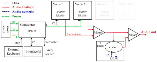
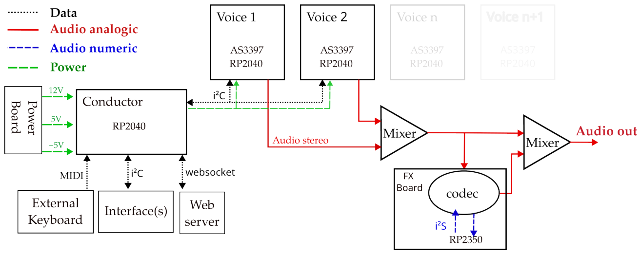
The general architecture of the polyphonic synthesizer, designed with modularity in mind, is shown in Figure 1.
Figure 1.
Overall architecture of the polyphonic synthesizer. For clarity, all the power bus lines are not shown.
2.1.1. Control and Communication Architecture
The conductor board, centered on the RP2040 microcontroller, manages musical input and dispatches it to the voice cards via the protocol. MIDI messages are accepted through a standard DIN port, USB, or a secondary bus from external controllers. The conductor board translates these inputs and multicasts them to the voices, emulating standard MIDI messages to maintain software compatibility. The AS3397 chips then generate the analog signals through subtractive synthesis, which are summed into a stereo audio bus.
2.1.2. Digital FX and Signal Processing
We developed an optional FX board to expand the synthesizer’s sonic capabilities. The summed analog signal is digitized by a Coolaudio V4220 codec and processed by a dedicated RP2350 microcontroller. Data transfer between the codec and the microcontroller relies on the protocol. The resulting digital effect signal is then mixed with the raw analog signal to produce the final synthesizer output, providing a flexible wet/dry balance.
2.1.3. Wireless and Physical Interfaces
Synthesizer parameters can be controlled wirelessly if the conductor board utilizes a Pi Pico W. The microcontroller hosts a lightweight web server and utilizes WebSockets to provide a real-time graphical user interface. This architecture enables rapid UI prototyping, as users can modify the HTML, CSS, and JavaScript code on the server to customize the control surface without altering the core synthesis firmware [10].
In addition to the web interface, we designed two physical control boards that communicate with the conductor board via its second interface. This modularity is a critical design choice: the interface fundamentally shapes the instrument’s capabilities and workflow. The same underlying hardware engine can function as a completely different instrument depending on the chosen control surface. For those replicating the synthesizer, this serves as an obvious point of customization, allowing them to tailor the user experience to their specific needs without redesigning the core synthesis architecture.
2.2. Architecture of a Single Voice
Overview of the AS3397 Chip
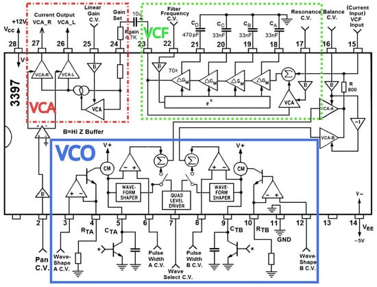
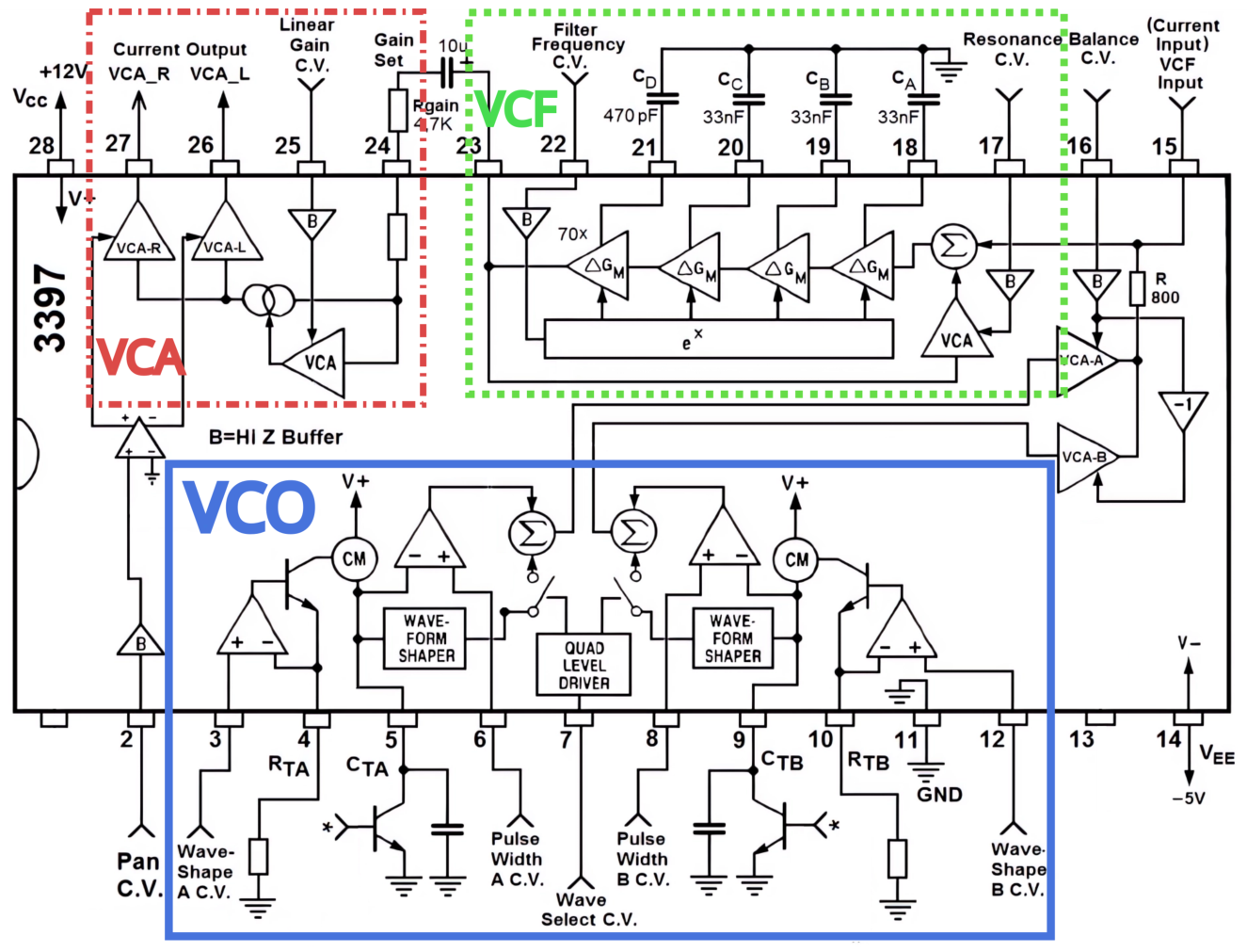
Figure 2 shows the structure of the AS3397 chip.
Figure 2.
Slightly simplified schematic block diagram of the AS3397 chip.
The Voltage Control Oscillators (VCO) employed in the AS3397 chip are of the Digital Controlled Oscillator (DCO) variety. A constant current source consistently charges the CTA capacitor. This capacitor can be quickly discharged by grounding it via a transistor. This switch is activated by a square wave voltage sent to the transistor’s base. The voltage, dictating the charge/discharge cycle frequency of the capacitor and, ultimately, the frequency of the note produced by the DCO, is generated by a PIO output of the RP2040, with its internal clock frequency adjusted to match the desired note frequency (see Supplementary Materials Section S3 for additional details).
Unlike other analog VCOs, frequency control by a microcontroller and subsequently by quartz oscillations ensures remarkable frequency stability and significantly simplified tuning. As will be discussed in Section 3, a DCO still requires calibration for its amplitude. We opted to directly measure the voltage ramp at the capacitor’s terminals using one of the RP2040’s ADCs, controlling the current generator’s control voltage with a PI (Proportional-Integrate) correction.
The voltage ramp at the capacitor’s terminals is sent to a waveform shaper, which outputs waveforms ranging from a ramp to a clipped triangle, through a triangle. Concurrently, the capacitor’s voltage is also directed to a comparator, whose output yields square waves with a duty cycle controlled by the comparison voltage (see Supplementary Materials Section S3.10). A multiplexer (referred to “Quad Level Driver” in the datasheet) allows the user to decide if they wish to sum the waveform shaper’s outputs (ramp/triangle) with the square waveforms from the comparator (see Supplementary Materials Section S3.11).
The AS3397 features two DCOs, the signals of which can be mixed using two VCAs (Voltage Controlled Amplifier) controlled by the Balance C.V. (Control Voltage) input. Before reaching the VCF (Voltage Controlled Filter) section, an external signal can be passively mixed with the outputs of the two DCOs. Here, we use this input to mix a DSO (Digital Signal Oscillator) generated by the RP2040. The VCF is a resonant 4-pole low-pass filter, schematically represented as a sequence of four first-order low-pass filters sharing the same pole. The filter’s cutoff frequency () is achieved using a fixed-value external capacitor to the chip (), but with a variable equivalent resistance R that’s voltage-controlled via an OTA (Operational Transconductance Amplifier) (see Supplementary Materials Section S4).
The signal exiting the VCF is DC-coupled to a primary VCA determining the general gain and two VCAs managing the stereo balance.
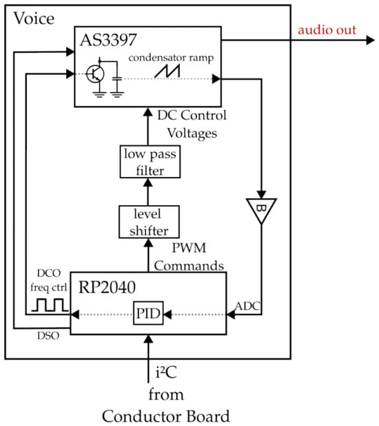
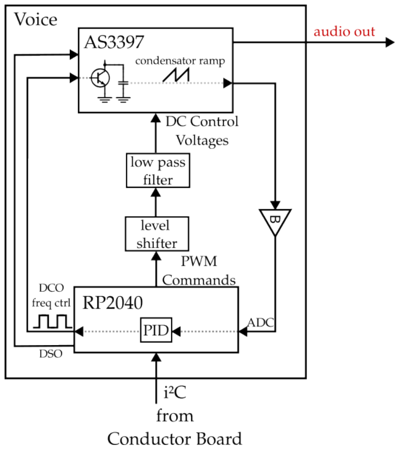
Figure 3 illustrates how, on a voice card, the RP2040 microcontroller drives the AS3397 chip. The microcontroller generates the 10 voltages required to control the inputs of the AS3397. It also produces two square signals that determine the frequencies of the two DCOs. This frequency is adjusted through a PI mechanism, based on digitizing the voltage across the charging capacitors’ ramps. Furthermore, to enrich the synthesizer’s sonic palette, the RP2040 produces a digitally generated audio signal to be mixed with the AS3397’s analog DCO signals.
Figure 3.
Schematic block diagram of the control of the AS3397 chip by the RP2040 micro-controller.
2.3. Hardware
2.3.1. Microcontroller: RP2040
Our specifications for the microcontroller responsible for controlling the AS3397 chip required it to be sufficiently fast to produce high-frequency PWM outputs with adequate resolution (as discussed in Section 2.3.4); well-documented with a significant user community; equipped with a suitable number of General Purpose Input Output (GPIO) pins to manage all the inputs of the AS3397 chip; cost-effective; energy-efficient; and readily available.
The need for a sufficiently high frequency ruled out the venerable ATMEGA328p, commonly used on the Arduino platform, which operates at 16 .
Introduced in January 2021 by the Raspberry Pi Foundation, the RP2040 has gained substantial traction two years post its release. The plethora of online resources and dedicated libraries make it a well-regarded choice. The microcontroller boasts dual ARM Cortex-M0+ cores, typically clocked at 133 , though it’s worth noting that overclocking them up to 250 is straightforward. With a cost hovering around 1 euro, a consumption rate of approximately 30 mA, 26 GPIO pins, and its current easy availability, the RP2040 presents an appealing option. Notable limitations include its RAM capacity of just 264 kB, which, fortunately, poses no issues for our project. Recently, the Raspberry Pi Foundation introduced the RP2350, a pin-compatible evolution of the RP2040 featuring an ARM Cortex-M3 core and expanded capabilities. We successfully tested this new microcontroller, confirming its suitability as a drop-in replacement for our project, but have not yet leveraged its additional computing power; consequently, we retained the RP2040 for our application.
While designing an electronic circuit to implement an RP2040 is well documented, we opted for the development board pi-pico, indeed, manually soldering the RP2040 chip, which comes in a QFN package, can be challenging for novices.
2.3.2. Power Supply
Each voice board requires three power rails: 5 to power the RP2040 and the control logic of the AS3397, and 12 and for the AS3397 analog circuitry. The operational amplifiers on the board are symmetrically powered by 5 and , with the exception of one dual op-amp powered between 12 and GND.
We propose a dedicated power board that utilizes a USB-C connection with Power Delivery (PD) to obtain a regulated 12 supply. From this primary rail, the 5 and rails are generated using off-the-shelf modules based on the TPS5430 chip. These three voltages are routed to the conductor board, which acts as the central hub for distribution to the voice cards, the optional FX board, and the user interface. The buck converter on the Raspberry Pi Pico boards then generates the local rail from the 5 supply.
Based on our estimations, a single voice card draws approximately 20 , 60 , and 25 from the 12 , 5 , and rails, respectively.
2.3.3. Communication via c
We elected to utilize the i2c protocol, operating at a bus frequency of 400 , to facilitate communication between the conductor board (master) and the rp2040 on the voice boards (slaves). The rationale behind this choice was its straightforward implementation, requiring only two wires and two pins on the rp2040. The bi-directional bus nature of i2c also allows the conductor board to receive feedback from the voice boards, particularly regarding the availability of voices, which aids in polyphony management. As a side note, the use of the broadcast mode that dispatches identical information to all voice boards helps conserve bandwidth.
On the C bus, the 8-bit messages emulate the protocol used by MIDI (Musical Instrument Digital Interface). This covers the management of notes (both ‘note on’ and ‘note off’), as well as velocity, aftertouch, control changes (MIDI CC), and other parameters. Additionally, extended MIDI is incorporated to overcome the standard MIDI’s limitation of 127 levels when necessary.
The addressing of each voice board is automatically carried out upon the startup of the conductor board. More specifically, a voltage, derived by dividing the 3.3 V generated by the conductor board and uniquely distributed to each voice board, is read by the third ADC of the voice board’s rp2040. This informs it of the specific i2c channel allocated to it. At the startup of the conductor board, it scans all the utilized i2c ports, enabling it to determine the synthesizer’s total polyphony (see Supplementary Materials Section S6).
2.3.4. Filtered Pulse Width Modulation as Digital to Analog Converters
The AS3397 chip features 10 voltage-controlled inputs that need to be driven by a voltage generated by the RP2040.
Initially, one might consider employing 10 Digital to Analog Converters (DAC). However, firstly the RP2040 lacks an integrated DAC, and generally, DACs built into microcontrollers don’t deliver high performance. An alternative would be to utilize a dedicated 8-channel DAC, such as the MCP3208. Yet, the associated chips for such solutions tend to be relatively expensive, often costing several euros.
A middle-ground solution is to use a single-channel DAC in tandem with a multiplexer. This setup enables sequential and rapid addressing of all the AS3397 inputs while synchronously adjusting the DAC. The AS3397 was designed with this mode of operation in mind, given its high-impedance inputs. By paralleling an input with a capacitor, the voltage can be retained as the multiplexer switches to the next AS3397 input.
Ultimately, this multiplexed approach requires a comparable number of discrete components to a filtered PWM method, negating any physical simplification while introducing additional routing and software complexity. Thus, driven largely by a preference for cost-efficiency and hardware accessibility, we decided to use the RP2040’s PWM outputs, filtering them to retain only the direct current component, effectively replicating the functionality of a DAC (see Supplementary Materials Section S5 for detailed mathematical and technical aspects).
To maximize the performance of this strategy, we overclocked the RP2040’s system clock to 200 . This allows for a favorable trade-off between resolution and modulation frequency:
- Resolution: By setting the PWM wrap value to 4096, we achieve a 12-bit resolution. This granularity is more than adequate for musical applications, far exceeding the standard 7-bit MIDI encoding.
- Frequency: At 200 , the 12-bit PWM operates at a carrier frequency of approximately . This frequency is well beyond the human audible range (20 –20 ), significantly reducing the risk of intermodulation artifacts within the audio signal.
The PWM signals are filtered using a simple first-order RC low-pass filter (, ). This configuration provides a cutoff frequency of . The resulting response time for the Control Voltages (CV) is approximately (), which is well within the 120 threshold for human perception of latency in musical control [11].
For parameters requiring even higher precision, such as the DCO waveform shape, we implemented a 16-bit control signal using passive summation of two 8-bit PWM signals. By combining a high 8-bit PWM with a low 8-bit PWM through a resistive divider with a 256:1 ratio ( and ), we achieve 65,536 distinct levels. In this 8-bit mode, the PWM frequency can be increased to 781 , allowing for even more aggressive carrier suppression.
Finally, the PWM signals from the RP2040 have an amplitude of . However, the AS3397 chip, which in some ways follows design principles from the 1980s, operates with voltages ranging from 0 to 5 . Some inputs, such as those for cut-off or for controlling the duty cycle of the square wave portion of the signal, even require negative voltages to reach their lower limits. Consequently, the filtered PWM outputs are routed through level shifters: specific ICs (CD4050) are used to transition from to 5 , while op-amp configurations are employed when a negative lower voltage boundary is needed.
2.3.5. Real-Time Calibration of the DCO via PI Feedback
A DCO allows for a precisely controlled oscillator frequency. However, the trade-off is the need to compensate for the ramp height, which varies with the frequency of the played note. For AS3397, the maximum value reached by the voltage ramp across the capacitor determines the waveform output of the waveform. We aim for this waveform to remain consistent regardless of the frequency of the synthesized note.
The maximum voltage is determined by the slope of the charge and its duration. The slope, or the charge rate, is influenced by three parameters: the capacitance C of the capacitor, the resistance R, and the charging voltage of the set .
The duration of charge T of the capacitor is dictated by the frequency f with .
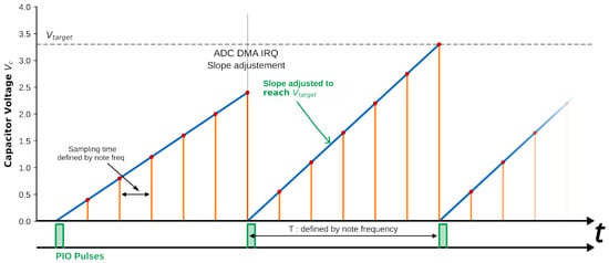
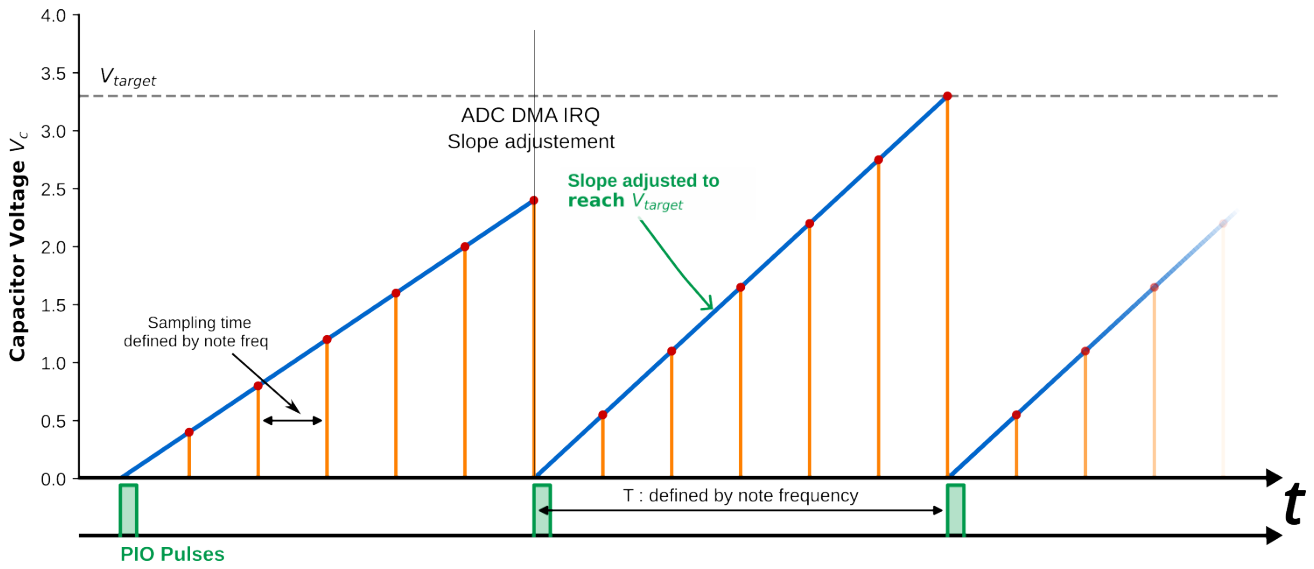
If we maintain a constant , higher frequency notes have less time to charge the capacitor, resulting in a lower compared to a lower frequency note under the same conditions. Hence, with a constant , the waveform output from the waveshaper will differ across frequencies. Consequently, we must adjust the charging voltage to ensure a consistent charging height, irrespective of the desired frequency f (Figure 4).
Figure 4.
Timing diagram illustrating calibration of DCO ramp height. The upper plot tracks the analog capacitor voltage over successive cycles. In Period 1, an insufficient charging slope fails to reach the target amplitude (). The system samples the waveform using the built-in ADC at a rate dynamically scaled to the note frequency, allowing for a fixed-depth buffer to span exactly one period T. The maximum recorded value is then extracted and compared against . The resulting error is processed by the PI controller, which increases the control voltage to achieve the correct slope in Period 2. The lower plot shows the corresponding discharge pulses generated by the RP2040’s PIO ports, ensuring strict pitch stability.
More specifically, the maximum value of the ramp is given by:
In practice, the time constant is not well-defined because the measurements of R and C can be imprecise, and these values change with temperature and aging. One solution is to calibrate each voice of the synthesizer during the startup phase. We have opted instead to implement a real-time feedback control system, where we measure the ramp height and then adjust the charging voltage to maintain a consistent ramp height regardless of the oscillator frequency. A first implementation, based on hardware interrupts and detailed in Supplementary Materials Section S3.6, produced satisfactory results. However, some waveform deviations remained at higher pitches, manifesting as subtle artifacts in the audio output.
In the updated version of the DCO control system, the capacitor discharge is no longer synchronized with a hardware timer and a fixed phase increment. Instead, we leverage the RP2040’s PIO (Programmable I/O) block to emit regularly spaced discharge pulses. The frequency of these pulses is adjusted by changing the internal clock driving the PIO, which in turn alters the pulse emission frequency. This architecture offers finer frequency resolution and improved stability, which in turn enhances the quality of frequency modulations and vibrato effects. However, this change introduces a trade-off: the ramp height is no longer measured directly at the end of each ramp cycle. To compensate for this, we continuously sample the capacitor voltage using the built-in ADC. From the sampled data, we estimate the slope of the ramp, which, combined with the known period of the note, allows us to infer the expected ramp height. The system then adjusts the charging voltage accordingly to maintain a consistent waveform shape. This method requires precise coordination of the ADC and DMA to ensure real-time sampling with minimal CPU overhead. Further refinements were made to optimize the accuracy of slope estimation. In particular, the ADC sampling period is now dynamically adjusted based on the note frequency: lower frequencies benefit from slower, but more evenly distributed sampling intervals to improve resolution and accuracy. Finally, to reduce the convergence time of the PI controller on each new MIDI note, previously computed optimal PD parameters are stored in a 128-entry lookup table, one for each MIDI note value. When a note is triggered, its corresponding calibration values are instantly retrieved, effectively acting as pre-tuned setpoints. It is worth noting that these calibration values could also be refined during the idle phases of each voice, allowing background optimization without interfering with active sound generation (see Supplementary Materials Section S3.8 for implementation details).
As recommended in the datasheet, we selected a capacitor for charging the VCO. Regarding the associated charge resistance, we followed the datasheet’s strategy of using two resistance regimes: a base resistance of for lower frequencies, and a fast-charging regime where a BS170F MOSFET connects a parallel branch of (a 10 and resistor in series) to ground. This reduces the effective equivalent resistance to . To maintain PI stability, the microcontroller dynamically scales the proportional gain by a factor of 32 when switching to . To prevent audible chattering and accommodate varying waveform amplitudes, the transition employs a hysteresis window: the system switches to above , and reverts to below .
2.3.6. FX Card
We designed an optional, dedicated FX card based on the RP2350 microcontroller to handle digital effects. This board connects to the conductor board via a standard 2 × 5 pin header. Audio input and output data transfer relies on the I2S protocol, implemented utilizing the RP2350’s Programmable I/O (PIO) blocks.
To accommodate different budgets and assembly constraints, the card supports three ADC and DAC configurations:
- The first approach uses the RP2350’s built-in ADC paired with a -bit PWM-RC filtered DAC for the output.
- The second option employs inexpensive, off-the-shelf I2S ADC (PCM1808) and DAC (PCM5102A) modules.
- The third configuration integrates the Coolaudio V4220 codec. This recent and cost-effective chip comes in an SSOP-28 package, making it significantly easier to hand-solder than the QFN packages typical of modern audio codecs. It is worth noting that the V4220 datasheet is poorly documented, as it confusingly mixes specifications from the original Cirrus Logic CS4220 and CS4221 chips it is based on.
2.3.7. PCB Design and Fabrication
We utilized KiCad (v9.0) for circuit design and PCB routing. Following an initial prototyping phase using homemade through-hole technology (THT) boards, the design transitioned to a two-layer Surface-Mounted Device (SMD) architecture.
To lower the barrier to entry for what can be a daunting project, we developed several board iterations. This includes a standalone monophonic board using THT components, designed as an educational entry point that is fully operational upon manual assembly.
The modular system utilizes a form factor smaller than 10 cm × 10 cm to minimize manufacturing costs. The voice cards are available in two variants: a 1206 SMD version for easier manual soldering and rework, and an 0603 version optimized for low-cost automated assembly (PCBA). The conductor board uses 1206 footprints for straightforward hand-assembly. A passive bus board unifies the system, connecting the voices to the conductor via standard 2 × 5 ( ) headers commonly found in Eurorack systems.
PCB fabrication and assembly (excluding the AS3397 and Pi Pico) were performed by JLCPCB (Shenzhen, China). Component tolerances are generally relaxed; for instance, variations in the charging capacitors are automatically compensated for by the PI loop (see Section 2.3.5). A notable exception is the pair of range-switching resistors, which must maintain a 1% tolerance to ensure their 32:1 resistance ratio.
2.4. Software
Software and Programming Environment
For optimal computational efficiency, the RP2040 and RP2350 microcontrollers are programmed in C++ rather than MicroPython. To ensure the project remains accessible to the hobbyist community, we utilized the Arduino-Pico core, which allows for Arduino syntax within the Arduino IDE (v2.1 or later).
Distinct firmware packages are provided for the voice cards (compatible with both the monophonic and polyphonic versions), the conductor board, and the FX card. For each module, we provide both the full source code and pre-compiled binaries in .uf2 format for easy flashing. The codebase is extensively commented, with additional technical documentation and implementation details available in the Supplementary Materials.
2.5. Implementation of the Digital Signal Oscillator
We calculate and set the PWM output values for each call of an interrupt running at 65,536 . These calculations are performed on the second core of the RP2040, leaving the first core to manage the control of the AS3397 chip. The primary role of the Digital Signal Oscillator (DSO) is to complement the analog path by providing essential audio features that the AS3397 lacks. At the time of writing, we have implemented wavetable synthesis and a third sub-oscillator. The DSO also allows for the generation of white noise, which is crucial for drum synthesis and sound effects.
Regarding its interaction with the analog signal path, the DSO output is mixed passively just before the resonant 4-pole VCF. It is important to note that while the DSO source is inherently digital, it is fully processed by the analog filter and VCAs, thereby preserving the overall warm and analog character of the synthesizer. This section is intentionally kept simple; however, the computational headroom of the RP2040 allows for the future implementation of more complex algorithms, such as Frequency Modulation (FM) or granular synthesis, to further enrich the sound palette of the AS3397’s analog subtractive synthesis.
2.6. Cost Estimation
A key objective of the PolyUAnalog project is to maintain a low cost-per-voice, making polyphonic analog synthesis accessible for researchers and hobbyists. Table 1 provides an overview of the estimated costs for the primary components of each module. Note that prices are approximate (excl. VAT) and vary based on quantity and supplier.
Table 1.
Bill of materials.
For an 8-voice configuration, a single voice card costs approximately 20 € fully assembled. Factoring in eight voices alongside the conductor, power, bus, and optional FX boards, the total electronics cost remains under 200 €. It is important to note that this estimate covers only the electronic modules and does not include the mechanical enclosure or the potentiometers required for the physical control interface.
By comparison, commercial analog polysynths are significantly more expensive. Behringer’s Pro-800 (8 voices) retails for approximately 400 €, while flagship models like the Arturia PolyBrute (6 voices) often exceed 2500 €. Even when accounting for the additional cost of a case and hardware controls, the PolyUAnalog offers a high-performance analog engine at a fraction of the price of commercial alternatives, while maintaining a fully open-source and repairable architecture.
3. Build Instructions
The complete design files, including KiCad projects, Gerbers, Bill of Materials (BOM), and firmware, are hosted on the Supplementary Materials.
3.1. Hardware Assembly
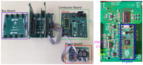
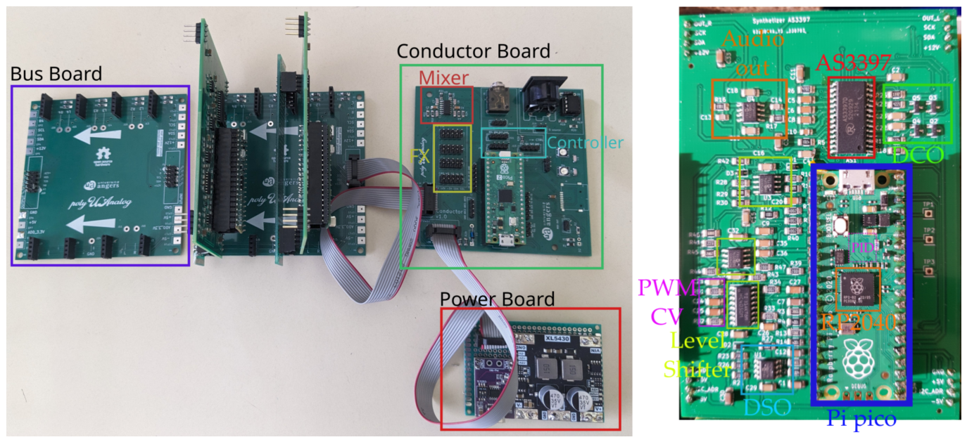
For the monophonic version, assembly consists of soldering the AS3397 chip and discrete components onto the monoboard (Figure 5), then mounting a Raspberry Pi Pico (Standard, 2, or W). The “W” variant is required if wireless web-interface control is desired.
Figure 5.
Left: Current iteration of the polyphonic synthesizer. The power board (prototype version shown) is linked to the conductor board via a standard 2 × 5 ( ) IDC ribbon cable. A similar cable connects the conductor to the passive bus board, where voice cards are mounted vertically. The architecture allows multiple bus boards to be tiled for system expansion via daisy-chaining. Right: Annotated view of a first-generation voice card utilizing 1206 SMD components. The primary electronic blocks are highlighted. Subsequent revisions feature a modified I/O pinout for vertical mounting into the bus board headers.
For the polyphonic system, the assembly follows a modular workflow:
- Power Supply: Populate the power board first. It is critical to verify the stability of the , , and rails before connecting other modules.
- Voice Boards: Solder one AS3397 and mount a Pi Pico to each voice board. These boards interface with the bus board via 90° pin headers.
- System Integration: Solder the conductor and bus boards. Connect the bus board to the conductor board using a standard 2 × 5 ( ) ribbon cable. The power board connects to the conductor board via an identical ribbon cable.
- Optional FX Card: If utilized, the FX card connects directly to the conductor board via the dedicated 1 × 4 header.
See also Supplementary Materials Section S2.
3.2. Firmware and Connectivity
Firmware installation is performed by flashing the provided .uf2 files to each microcontroller via USB. Each module (Voice, Conductor, FX) requires a specific binary; these are provided as pre-compiled files optimized for the Raspberry Pi Pico (RP2040), Pico 2 (RP2350), and Pico 2W. For advanced customization, the source code can be recompiled using the Arduino IDE with the arduino-pico core.
Musical data can be transmitted to the conductor board through four primary methods:
- Standard MIDI: Via the physical MIDI-IN DIN port.
- USB Host: Connecting a USB-MIDI keyboard directly to the conductor’s Pi Pico using a USB OTG (On-The-Go) adapter.
- USB Device: Connecting the conductor board to a computer, where it appears as a class-compliant MIDI device.
- Wireless: Using the web-based MIDI interface if a Pi Pico W is installed.
Synthesizer parameters can be adjusted via a 4-pin serial interface. We provide two reference control surface designs in the Supplementary Materials: a compact version for the monophonic board and a full-scale interface for the polyphonic system.
4. Operating Instructions
To operate the PolyUAnalog, the system must be powered via the dedicated power board (typically using a 12 USB-C PD source). Upon power-up, the synthesizer is immediately functional. Notably, the implementation of DCOs and real-time PI feedback (see Section 2.3.5) eliminates the traditional warm-up period required by discrete analog oscillators for pitch stability.
Audio output is provided via a standard jack suitable for high-impedance headphones or line-level inputs of an external amplifier or audio interface.
Performance and Parameter Control
Users can interact with the synthesizer in three ways:
- MIDI Input: Notes and performance data (velocity, aftertouch) are sent via the MIDI-IN port or USB. The conductor board handles voice allocation automatically across the available voice cards.
- Sound Synthesis: Parameters such as filter cutoff, resonance, envelope timings, and oscillator waveforms are adjusted in real-time using either the dedicated hardware control surface or the browser-based web interface.
- FX Processing: If the FX card is installed, the wet/dry mix and effect parameters are managed through the conductor board, processing the summed analog signal through the digital DSP loop before the final output.
5. Validation
5.1. Measurement Equipment and Protocol
Audio signals were recorded using a consumer-grade M-Audio M-Track audio interface with a sampling rate of and 16 bit resolution. Because this interface is AC-coupled, it is unsuitable for capturing static offsets; consequently, all direct current (DC) measurements were performed using an Owon XDM1041 digital multimeter (DMM). For transient phenomena and high-frequency signal analysis, we utilized a Tektronix oscilloscope with a 60 bandwidth.
A custom Python (v3.11) script orchestrated the testing protocol by sending MIDI messages to the synthesizer while simultaneously capturing the resulting audio output. This setup enabled systematic, reproducible characterization of the synthesizer’s various configurations under full MIDI control.
5.2. Tuning of the DCO Amplitude via PI
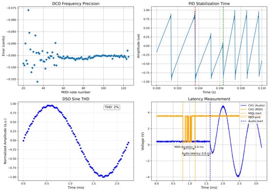
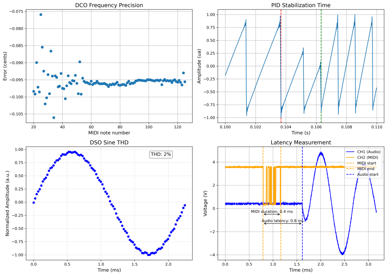
The primary strength of digitally controlled oscillators (DCOs) lies in their excellent frequency accuracy. To quantify this, each of the 127 MIDI notes was recorded as a steady tone and analyzed by fitting the dominant peak of the FFT magnitude spectrum in order to extract the fundamental frequency. Figure 6 (top left) shows that the deviation between the measured DCO frequency and the ideal MIDI pitch remains below 0.1 cent over the entire range, which is far below the typical human just-noticeable difference of about 6 cents [12]. This confirms that the automatic tuning routine performs as intended.
Figure 6.
Characterization of the synthesis engine and system performance. (Top left) DCO frequency precision; the pitch error remains under cent, which is negligible and likely limited by the measurement resolution. (Top right) PI stabilization of the ramp voltage following a note trigger. One can note the phase-locked nature of the PI correction, where the sampling rate scales with pitch to maintain a 2-cycle settling time. (Bottom left) Single period of a 440 sine wave generated by the DSO via dual 8-bit filtered PWM, achieving a THD of 2%. (Bottom right) Latency measurement showing the software and communication delay between the completion of the MIDI message and the onset of the analog audio signal.
However, as a counterpart to this frequency accuracy, the DCO requires an adjustment of the ramp height for each oscillator frequency. In the AS3397, the waveshaper uses the maximum ramp voltage to derive the final waveform; improper compensation therefore leads to frequency-dependent changes in the ramp amplitude, and consequently to small timbral variations from note to note.
To evaluate the dynamic behavior of the control loop, several note transitions between different MIDI pitches were analyzed (see Figure 6, top right). To ensure consistent performance across the frequency range, the PI feedback loop employs a note-synchronous sampling strategy where the ADC monitors the signal of each DCO alternately (Section 2.3.5). By dynamically adjusting the sampling period to twice the oscillation period of the current note (), the system stabilizes the waveform within exactly two charge-discharge cycles regardless of the target frequency. Physically, this corresponds to a settling time ranging from 70 for low-range keys to 5 for the A4 (440 ) reference; in all cases, these effects remain imperceptible to the ear.
5.3. Filtered PWM Control Voltage Signal
Figure S29 in Supplementary Materials displays the settling time and the residual oscillations of the control voltages (CV) obtained by filtering PWM signals with different carrier frequency corresponding to different bit-resolution of the CV. For example, with a carrier frequency of and a filtering frequency of . The residual fluctuations of around at in the CVs are inaudible, and the response time, being below the physiological limit, is not perceptible.
Figure S30 in Supplementary Materials illustrates the voltage response curve of the 14-bit and 8-bit DAC thus obtained. The response is linear except from the first low value point.
These results confirm that the low-pass-filtered PWM outputs of the microcontroller can be reliably used as digital-to-analog converters for driving the AS3397 chip.
5.4. DSO Characterization
As explained earlier, the Digital Signal Oscillator is generated by combining two 8-bit low-pass-filtered PWM outputs of the microcontroller to form a 16-bit control signal. Figure 6 bottom left shows a 440 sine wave produced by this system, after passing through the VCF (with its cutoff frequency set high enough to leave the waveform unaffected) and the VCA at a moderate gain setting. The resulting total harmonic distortion (THD) is approximately 2%, demonstrating that, despite lacking a true DAC, the RP2040 is capable of generating good quality audio-frequency signals.
5.5. VCF Characterization
To evaluate the Voltage Controlled Filter (VCF) performance against the manufacturer’s specifications, we conducted two complementary sets of measurements. First, a discrete frequency sweep was performed using the DSO-generated sine wave, recording the output amplitude for each of the 127 MIDI notes to construct a Bode magnitude plot. Second, during the prototyping phase, white noise was injected via Pin 15, and the system’s transfer function was derived through cross-correlation between the input and the final analog output.
While the AS3397 datasheet describes a 4-pole low-pass filter architecture, which should theoretically yield a −80 dB/decade (−24 dB/octave) roll-off, our experimental observations consistently indicated a slope closer to −40 dB/decade, characteristic of a second-order system (see Supplementary Materials). Our measurement system has a noise floor of approximately −50 dB. This technical limit makes it difficult to accurately observe the steep attenuation expected from a 4-pole filter. Even when analyzing the signal in the frequency range well above the noise floor, we measured a slope of −12 dB/octave instead of the theoretical −24 dB/octave. A more precise characterization would require higher-performance equipment and the isolation of the VCF circuitry from the other internal stages of the AS3397 chip. While this will be addressed in future research, it remains beyond the scope of this article.
The onset of self-oscillation of the VCF occurs at approximately on the resonance control voltage, which is lower than the nominal value of approximately 4 specified in the AS3397 datasheet. Using this self-oscillating regime, we measured the exponential relationship between the cutoff control voltage and the actual cutoff frequency (see Supplementary Materials). The AS3397 datasheet specifies a 14-octave filter range for a control voltage (CV) between and 5 . Because a large portion of this range falls outside the useful musical spectrum (below 20 or above 15 ), we mapped the CV range to focus specifically on these frequency limits.
5.6. Latency
As shown in Figure 6 bottom right, the note triggering delay between the reception of an incoming MIDI message and the onset of the corresponding audio signal was measured at approximately 1 . This value effectively reaches the intrinsic transmission limit of the MIDI protocol itself ( for a standard 3-byte Note On message). For comparison, most software instruments typically exhibit latencies between 5 and 10 due to audio buffer constraints. Such performance ensures that the system remains virtually instantaneous for audio applications [13].
5.7. Subjective Playing Experience
While inherently subjective, the general playing experience offered by the PolyUAnalog is remarkably close to that of a commercial analog synthesizer. The instrument responds immediately to performance gestures, the envelopes and modulation paths behave musically, and the overall timbral character is cohesive and expressive.
6. Conclusions
We have presented the PolyUAnalog, a fully open-source, low-cost polyphonic synthesizer built around the AS3397 analog voice chip and controlled by a network of RP2040 microcontrollers. By combining a modular hardware architecture with a flexible software stack, the instrument offers a level of transparency, reparability, and extensibility that remains rare in the world of analog polysynths. The detailed measurements confirm that the system meets the technical requirements expected of a modern musical instrument, while the subjective evaluation shows that it responds and sounds in a manner comparable to commercial synthesizers.
Future work will focus on expanding both the sonic and functional ecosystem of the PolyUAnalog. This includes the development of an two analog FX board featuring for the first a dedicated distortion and for the second a Bucket Brigade Device (BBD) chorus circuits, as well as a dedicated physical modulation matrix to provide a more tactile approach to complex routing. The system’s modular architecture and power distribution also naturally lend themselves to a Eurorack-compatible format, offering a pathway for integration into broader modular environments. On the software side, we plan to implement advanced preset management inspired by classic implementations such as the Oberheim Matrix-1000. Beyond raw functionality, fine-tuning the response curves of envelopes and modulation paths will be essential to transition the platform from a robust engineering proof-of-concept into a truly refined and expressive musical instrument. Finally, to further support the DIY community, we will provide a comprehensive suite of diagnostic scripts and a step-by-step assembly protocol, emphasizing an incremental build strategy to ensure the monophonic core is fully operational before scaling to full polyphony.
By making both the hardware and software fully open, our intent is to encourage experimentation, modification, and collective improvement. We hope this project will serve as a foundation for future designs, whether educational, artistic, or technical, and contribute to the ongoing revival of hands-on, community-driven analog electronics.
Supplementary Materials
The following supporting information can be downloaded at https://www.mdpi.com/article/10.3390/hardware4030014/s1. The following supporting information contains:
| Name | Type | Description |
| SI.pdf | Document | Electronic Supplementary Information featuring system photographs, theory, and additional characterization measurements. |
| OpenData.zip | Archive | Raw data and processing scripts used to generate the figures and plots presented in the manuscript. |
| polyUAnalog_repo.zip | Archive | Including C++ firmware for all boards, KiCad hardware design files (schematics and PCBs), and technical documentation. |
Author Contributions
D.G. and M.L. methodology, software, validation, data curation; M.L. writing—original draft preparation; D.G. and M.L. writing—review and editing. All authors have read and agreed to the published version of the manuscript.
Funding
This research received no external funding.
Data Availability Statement
The original contributions presented in this study are included in the article and its associated Supplementary Materials. Specifically, the raw data and processing scripts required to reproduce all figures and plots are provided in the Supplementary Materials (Archive: OpenData.zip). Additional technical details or specific experimental measurements are available upon reasonable request from the corresponding authors.
Acknowledgments
The authors warmly thank Mohand-Tahar Amrous, Julian Le Borgne and Adnane Mahamat Madani Fadoul for their valuable work and technical assistance during their internship. During the preparation of this manuscript, the authors used Large Language Model chatbot to refine technical English phrasing. Every suggestion was critically reviewed, edited, and verified by the authors to ensure scientific accuracy. The authors take full responsibility for the final content of this publication.
Conflicts of Interest
The authors declare no conflicts of interest.
Abbreviations
The following abbreviations are used in this manuscript:
| ADC | Analog-to-Digital Converter |
| AS3397 | Analog Synth Voice Chip by ALFA RPAR |
| BJT | Bipolar Junction Transistor |
| BOM | Bill of Materials |
| CV | Control Voltage |
| DAC | Digital-to-Analog Converter |
| DCO | Digitally Controlled Oscillator |
| DMA | Direct Memory Access |
| DSO | Digital Signal Oscillator |
| FFT | Fast Fourier Transform |
| FX | Effects (audio processing) |
| GPIO | General Purpose Input/Output |
| I2C | Inter-Integrated Circuit |
| I2S | Integrated Interchip Sound |
| IC | Integrated Circuit |
| LDO | Low Dropout Regulator |
| MCU | Microcontroller Unit |
| MIDI | Musical Instrument Digital Interface |
| OTA | Operational Transconductance Amplifier |
| PCB | Printed Circuit Board |
| PCBA | Printed Circuit Board Assembly |
| PD | Power Delivery |
| PI | Proportional–Integral (controller) |
| PIO | Programmable I/O (RP2040 subsystem) |
| PWM | Pulse-Width Modulation |
| RP2040 | Dual-core ARM Cortex-M0+ Microcontroller by Raspberry Pi |
| SMD | Surface-Mount Device |
| THD | Total Harmonic Distortion |
| VCA | Voltage-Controlled Amplifier |
| VCF | Voltage-Controlled Filter |
| VCO | Voltage-Controlled Oscillator |
References
- Roth, J.; Keller, D.; Castañeda, O.; Studer, C. Live Demonstration: An Aliasing-Free Hybrid Digital-Analog Music Synthesizer Prototype. In Proceedings of the 2023 IEEE International Symposium on Circuits and Systems (ISCAS); IEEE: Piscataway, NJ, USA, 2023. [Google Scholar] [CrossRef] [Scilit]
- Valimaki, V.; Pekonen, J.; Nam, J. Perceptually informed synthesis of band-limited classical waveforms using integrated polynomial interpolation. J. Acoust. Soc. Am. 2012, 131, 974–986. [Google Scholar] [CrossRef] [Scilit] [PubMed]
- Thorén, C.; Kitzmann, A. Replicants, Imposters and the Real Deal: Issues of Non-Use and Technology Resistance in Vintage and Software Instruments. First Monday 2015, 20, 11. [Google Scholar] [CrossRef] [Scilit]
- Beverland, M.B.; Fernandez, K.V.; Eckhardt, G.M. Consumer Work and Agency in the Analog Revival. J. Consum. Res. 2024, 51, 719–738. [Google Scholar] [CrossRef] [Scilit]
- Nelson, A.J.; Anthony, C.; Tripsas, M. “If I Could Turn Back Time”: Occupational Dynamics, Technology Trajectories, and the Reemergence of the Analog Music Synthesizer. Adm. Sci. Q. 2023, 68, 551–599. [Google Scholar] [CrossRef] [Scilit]
- Jordà, S.; Geiger, G.; Alonso, M.; Kaltenbrunner, M. The Reactable: Tangible and Tabletop Music Performance. Int. J. Arts Technol. 2010, 3, 268–287. [Google Scholar] [CrossRef] [Scilit]
- Goulding, C.; Derbaix, M. Consuming material authenticity in the age of digital reproduction. Eur. J. Mark. 2019, 53, 1–20. [Google Scholar] [CrossRef] [Scilit]
- Roundy, P.T.; Bayer, M.A. Life After Digital Displacement: Analog Entrepreneurship and the Revitalization of Legacy Technologies. J. Res. Mark. Entrep. 2024, 26, 191–211. [Google Scholar] [CrossRef] [Scilit]
- Tarragona, M.; Davoine, F.; Eirea, G. The Synthesizer: A Versatile Active-Learning Tool for Electrical Engineering. In Attracting Young People to Engineering: ALE 2014, Proceedings of the 12th International Workshop on Active Learning in Engineering, Caxias do Sul, Brazil, 8–10 December 2014; Villas-Boas, V., Giovannini, O., Eds.; Associação Brasileira de Educação em Engenharia (ABENGE): Brasília, Brazil, 2014. [Google Scholar]
- Michon, R.; Smith, J.O.; Wright, M.; Chafe, C.; Granzow, J.; Wang, G. Mobile Music, Sensors, Physical Modeling, and Digital Fabrication: Articulating the Augmented Mobile Instrument. Appl. Sci. 2017, 7, 1311. [Google Scholar] [CrossRef] [Scilit]
- Gandhi, P.H.; Gokhale, P.A.; Mehta, H.B.; Shah, C.J. A Comparative Study of Simple Auditory Reaction Time in Blind (Congenitally) and Sighted Subjects. Indian J. Psychol. Med. 2013, 35, 273–277. [Google Scholar] [CrossRef] [Scilit] [PubMed]
- Demany, L.; Semal, C. Learning to perceive pitch differences. J. Acoust. Soc. Am. 2002, 111, 1377–1388. [Google Scholar] [CrossRef] [Scilit] [PubMed]
- Schmid, A.; Ambros, M.; Bogon, J.; Wimmer, R. Measuring the Just Noticeable Difference for Audio Latency. In Proceedings of the 19th International Audio Mostly Conference: Explorations in Sonic Cultures; ACM: New York, NY, USA, 2024; pp. 325–331. [Google Scholar] [CrossRef] [Scilit]

Disclaimer/Publisher’s Note: The statements, opinions and data contained in all publications are solely those of the individual author(s) and contributor(s) and not of MDPI and/or the editor(s). MDPI and/or the editor(s) disclaim responsibility for any injury to people or property resulting from any ideas, methods, instructions or products referred to in the content. |
© 2026 by the authors. Licensee MDPI, Basel, Switzerland. This article is an open access article distributed under the terms and conditions of the Creative Commons Attribution (CC BY) license.