


Abstract
Aircraft electrification requires high-performance thermal management systems able to cool down power-plants with increasing power densities in electric aircraft motors. The demanding mission profiles and the request for compact electric components, in fact, induce high temperatures in power-plant systems that must be cooled by proper thermal management systems, to assure efficiency and reliability. This paper investigates and compares two promising approaches for the cooling of megawatt-order electric motors for aviation applications: nanofluid-based liquid cooling and radial-tube systems. Nanofluids are an innovative approach to system cooling leveraging the physical properties of the coolant; radial tubes, conversely, represent a structural solution aimed at improving the heat removal. In particular, nanofluids are composed of colloidal suspensions of nanoparticles in a base fluid, enabling enhanced thermal conductivity and convective heat transfer coefficients compared to conventional coolants. Radial tubes improve heat removal through optimized conduction paths and increased surface-to-volume ratios without altering the working fluid. Through numerical analysis carried out by using commercial Computational Fluid Dynamics (CFDs) tools, results highlight the main advantages of the two systems: nanofluids provide a significant average heat transfer enhancement on the tooth, while the radial tubes involve a strong increase in the global heat exchange despite a larger oil flow rate.
1. Introduction
Climate change represents one of the most pressing global challenges of the 21st century, having significant impacts on ecosystems, human health, and industrial sectors, including aviation. The issue is well known since the late decades of the last century, and since then, the international community has promoted strategies aimed at reducing greenhouse gas emissions, increasing energy efficiency, and accelerating the adoption of low-carbon technologies across all transportation domains [1,2,3]. Several sectors have been impacted by regulations aimed at the reduction of emissions, including aviation, addressed to introduce innovative technologies to reduce Carbon Dioxide (CO2) emissions over the whole aircraft lifecycle. Innovative propulsion systems are one of the pillars to achieve emission reduction targets imposed by the international community. Among the several technologies proposed, electric propulsion has emerged as one of the most promising for small aircraft (less than 9 passengers), while hybrid-electric aircraft is promising for aircraft up to 30 passengers [4].
Modern electric aircraft require megawatt-class electric motors able to deliver high specific power. To maintain low mass and compact size, operating electric machines’ current densities must be increased, resulting in high heat fluxes, which can potentially compromise efficiency, reliability and component life cycle, if not properly dissipated. Thus, stringent constraints on their thermal management systems must be respected. This challenge is particularly important in the aeronautic sector, where stringent weight, safety and reliability requirements have to be met, making thermal management one of the main bottlenecks for next-generation propulsion systems [5].
Nanofluid-based cooling systems have gained considerable attention among the promising solutions currently under investigation. Nanofluids are obtained by dispersing nanoparticles—such as alumina or graphite—into a base coolant. Their use can significantly enhance thermal conductivity and heat transfer capabilities. Recent studies conducted at the Italian Aerospace Research Centre (CIRA) showed that the addition of nanoparticles to diathermic oils can cause up to a 60% increase in heat transfer performance at fixed mass flow rates [5]. As a consequence, a sensible reduction in motor operating temperatures for high-power—megawatt-class electric motor—aircraft applications has been observed. Similar findings have been reported in the broader literature addressing electronic and electromechanical thermal management, where nanofluids exhibit improved convection coefficients and energy-efficient cooling potential [5,6].
In parallel, other solutions based on advanced thermal management system (TMS) layouts are being investigated, e.g., radial tubes, hollow shaft oil injection channels, and heat pipe-based architectures. The German Aerospace Center (DLR) recently highlighted that channel-based cooling and heat pipe systems are among the most efficient solutions for achieving high cooling performance with minimal weight impact in electrified aircraft propulsion systems. In addition, advanced thermal management systems based on radial oil injection channels have been proposed for megawatt-class motors to enable direct coolant delivery to hot spots, improving internal heat distribution within permanent magnet cavities—an approach particularly suitable for compact propulsion units [7,8].
Given the wide range of cooling technologies currently available, a systematic comparison between nanofluids and radial-tube-based cooling solutions is essential to determine the most suitable approaches for next-generation electric aircraft. Although both methods address critical thermal management challenges, in fact, they differ from several standpoints, such as integration complexity, weight impact, maintenance requirements, and long-term operational reliability. Understanding the potentiality and limitations of the two technologies is fundamental to designing a proper propulsion architecture, aligning with the aviation industry’s push toward lower environmental impact and greater energy efficiency.
This paper aims to deliver a comprehensive evaluation of nanofluid cooling and radial tube techniques, examining their thermal performance, system-level implications, and potential roles within future sustainable aviation platforms.
The radial-tube configuration should not be interpreted as a purely geometrical modification operated under the same coolant-flow constraint as the baseline case. It represents a different cooling architecture, in which an additional oil-supply path through the hollow shaft and radial tubes modifies both the coolant distribution and the total coolant delivered to the machine.
Therefore, the observed temperature reduction is due to the combined effect of increased coolant supply, centrifugal oil redistribution, and radial-tube geometry.
In fact, the radial tubes introduce an additional oil-supply path through the hollow shaft, thereby increasing the total coolant delivered to the machine. Consequently, the thermal improvement obtained with this configuration must be interpreted as the combined result of centrifugal oil redistribution, direct rotor-side injection, increased local convection, and increased total coolant flow rate. For this reason, the radial-tube solution is discussed as an alternative cooling architecture rather than as a purely geometrical modification under identical hydraulic constraints.
It can be noticed that for the radial tubes, the mass flow increase is about 50%, while h increases more than 440%. Considering that h linearly increases with mass flow, it is clear that radial tubes have a huge effect on the h improvement.
Although nanofluids and radial-tube oil injection have both been investigated as advanced cooling approaches for high-power electrical machines, most available studies address these techniques independently. Nanofluid-based solutions are a passive technique to enhance cooling, mainly focused on enhancing the effective thermophysical properties of the coolant. On the other hand, radial-tube or centrifugal oil-injection systems are an active system since they primarily improve coolant delivery and local flow distribution. A direct comparison between these two cooling philosophies, applied to the same high-power aircraft electric motor and evaluated under the same thermal loading condition, remains limited. Therefore, the present work contributes by comparing a coolant-property enhancement strategy with a coolant-architecture enhancement strategy within a common CFD framework.
No dedicated experimental validation was available for the complete motor configuration analyzed in this work. Therefore, the CFD results should be interpreted primarily as comparative numerical trends obtained under a consistent modeling framework. Experimental validation of temperature distribution, pressure losses, HTC, and wall shear stress is required before extending the results to final design qualification.
1.1. Background on Electric Aircraft Propulsion
The development of electric aircraft propulsion has received a boost following the issues related to global warming, with the consequent need to reduce fuel consumption, emissions, and noise across the global aviation sector. Electrification introduces a paradigm shift in aircraft design, enabling innovative configurations, such as electric/hybrid-electric powerplants and distributed electric propulsion, which were once impractical with conventional aircraft powertrains. Recent reviews highlight that the use of electric propulsion systems allows new airframe–propulsion integration approaches, offering both enhanced aerodynamic efficiency and operational flexibility compared to existing aircraft [9].
Generally, electric aircraft propulsion systems are divided into fully electric, hybrid-electric, and turboelectric architectures. Each one of these architectures offers different benefits and drawbacks, for example, hybrid-electric systems combine electric motors with conventional engines to optimize performance across different flight phases, reducing overall fuel consumption and extending the range with respect to full electric architectures, which use batteries only. National Aeronautics and Space Administration (NASA) Glenn Research Center researchers underline that hybrid configurations might substantially improve efficiency and reduce emissions, forming a promising concept for future green aircraft [10].
The advancements in key electric propulsion enabling technologies—e.g., high efficiency electric motors, enhanced energy storage and lightweight materials—are improving the feasibility of electric propulsion for aviation purposes. In parallel, several studies have highlighted that increased electrification can reduce block fuel burn and emissions through optimized propulsion system architectures and proper energy management strategies, making electric propulsion architecture a promising pathway toward green aviation meeting decarbonization goals [11].
Despite the abovementioned potential in terms of environmental impact benefits, electric aircraft propulsion still faces several challenges, mainly due to the energy density, mass, and thermal management of current battery systems. With respect to the latter point, it must be noticed that the need for advanced cooling methods grows with the rising power demands of electric motors and power electronics. In parallel, the integration of an electric powerplant is accompained by new certification, design and control complexities to be addressed before such technology can be considered mature for its daily application on novel aircraft. Nonetheless, ongoing research and technology demonstrations highlight the continuous progress toward practical, scalable electric propulsion solutions for the next generation of sustainable aircraft [9].
1.2. Importance of Thermal Management for High-Power Electric Motors
TMS plays a vital role in the performance, reliability, and safety of electric aircraft propulsion systems. With the escalation of power requirements, electric motors, energy storage systems, and power electronics operate at increasingly higher power densities, producing higher thermal load to dissipate. Recent studies on electrified propulsion architectures, in fact, demonstrate and emphasize that the shift toward high-power electric systems—often needed for takeoff and climb phases, as well as for distributed propulsion architectures—substantially increases thermal loads, which cannot be handled by using conventional cooling systems used for current aircraft architectures [11]. Thus, efficient heat dissipation becomes essential to prevent system component degradation and efficiency losses.
Electric propulsion systems for aircraft are mainly based on high-efficiency motors and power electronics, operating typically at elevated temperatures due to resistive and switching losses. NASA’s studies on megawatt-class electric machines have demonstrated that achieving high power density while keeping low mass inherently demands advanced TMS solutions to guarantee that winding temperatures, magnetic materials, and power semiconductor junctions operate within allowable limits. Without adequate cooling, in fact, component efficiency drops and thermal damages may occur, jeopardizing mission performance and safety [12].
In addition, it must be underlined that the integration of electric propulsion into next-generation aircraft architectures introduces additional thermal complexities. Energy management strategies, in fact, often require the sharing of dynamic loads among multiple components. This peculiarity of innovative hybrid-electric architecture requires sophisticated cooling approaches able to adapt to different and variable operating conditions, keeping compliance with aviation certification standards. Electrified propulsion system reviews underline that TMSs are one of the most important technical barriers limiting the scalability of a solution, with current technologies often unable to meet the demanding constraints in terms of efficiency, reliability, and weight of aviation applications [9].
Thus, TMSs influence the feasibility and design choices of aircraft requiring the use of megawatt-scale electric propulsion and more compact system architectures. Therefore, innovations in cooling technologies, including advanced fluids, novel configurations, and integrated thermal management systems, are fundamental enablers in the transition to sustainable electrified aviation [11].
1.3. Limitations of Current Cooling Technologies
Current cooling technologies face several critical limitations hindering their applicability to high power densities and thermal loads needed by commercial next-generation aircraft. In particular, as electrified propulsion architectures move towards higher electrical power values, traditional cooling methods—e.g., air cooling or conventional liquid cooling loops—struggle to assure that component temperatures are within safe operational ranges. Electric propulsion architecture reviews emphasize that the increase in system electrification induces higher thermal stresses due to the concentration of heat generation in compact converters, inverters, and motor windings. These thermal loads usually exceed the cooling capacity of existing TMS solutions, leading to efficiency degradation and potential component failure [11].
In addition, aeronautic applications also require stringent mass and volume constraints and certification needs. Traditional liquid cooling systems often need heavy heat exchangers, piping, and pumps, not fitting aircraft weight requirements. Moreover, the dynamic and variable power demands of electric aircraft further stress the existing cooling systems’ limitations. During high-load phases—i.e. takeoff and climb—rapid temperature spikes can occur, requiring fast-response thermal control mechanisms that conventional TMSs are not able to offer. A further complication arises in hybrid-electric and turboelectric architectures, which distribute heat across multiple powertrain components, each one characterized by distinct cooling requirements and thermal time constants [9,12].
In addition, current cooling technologies often fall short in terms of maintainability and reliability, which are two key parameters for aviation certification. Batteries, electric motors, and high-power inverter modules demand strict thermal regulations to prevent hot spots and maintain long-term performance stability. The increasing integration of advanced materials, compact electric motors, and high switching-frequency power electronics further reduces available heat-dissipation surfaces, pushing traditional TMSs to their performance limits. These challenges underline the need for innovative, highly efficient, and lightweight TMSs capable of supporting future green hybrid-electric propulsion systems [11].
1.4. Aim and Scope of the Study
The aim of the present work is to evaluate and compare two possible next-generation cooling solutions for electric aircraft motors: nanofluid-based cooling and radial-tube cooling TMSs.
The two proposed architectures are compared by using a commercial CFD tool to assess their effect on a megawatt-class electric motor temperature distribution. This focus is consistent with ongoing research efforts aimed at the development of high-efficiency thermal control supporting megawatt-class electric motors for future green commercial aircraft concepts [12].
This work aims to support the development of more efficient, lightweight, and certifiable cooling technologies designed for the next generation of hybrid-electric propulsion systems for sustainable aviation. Thanks to a comparative assessment of nanofluids and radial tube configurations, this paper tries to define promising solutions to meet the growing thermal requirements of high-power electric aircraft motors, which are one of the possible solutions to enable aviation decarbonization.
2. Thermal Challenges in Electric Aircraft Motors
Electric aircraft motors usually operate at high power densities, maximizing propulsion efficiency and minimizing system weight. For this reason, propulsion system thermal management is one of the most critical design challenges to be faced by engineers to make this power-plant solution feasible for real-life applications [13,14]. Although electric motors can achieve efficiencies well above 90%, the losses are concentrated in a small volume, with significant heat generation in power electronics, rotor magnets, stator cores and motor windings [14]. Conventional turbomachinery can use the high-temperature exhaust to dissipate heat, while electric propulsion systems have no high-temperature exhaust flows naturally rejecting heat. Moreover, electric motor components need to operate in a relatively low thermal range to guarantee their efficiency and operational safety. In addition, aircraft operate in low air density at high altitude, requiring strict mass and drag constraints, and variable duty cycles, which further limit the effectiveness of conventional state-of-the-art air cooling [13]. For these reasons, it is mandatory to develop advanced thermal management solutions, such as, for example, advanced liquid cooling, direct winding cooling, oil spray systems, heat pipes, and integrated thermal–electromagnetic co-design. However, these solutions introduce trade-offs between cooling performance, system complexity, reliability, and weight and efficiency penalties. As future aircraft aim for megawatt-class electric propulsion, effective thermal management is increasingly a key enabler for scalability, safety, and long-term reliability of electric aircraft motors [15,16].
2.1. Heat Generation Mechanisms in Electric Motors
Multiple loss mechanisms linked to electrical, electromagnetic and mechanical phenomena within electric motors induce the generation of heat. Usually, the most important heat loss contribution is due to copper losses, originating from Joule heating [13,17] in the stator windings. These losses scale with the square of the phase current, making them particularly critical in high-power-density and overload operating conditions [13,14]. Additional losses are known as iron losses. They include hysteresis and eddy current losses in stator and rotor laminations, becoming increasingly significant at high electrical frequencies and rotational speeds, which are typical operating conditions of electric motors for aviation applications [14]. A third source of thermal losses is the rotor losses, such as eddy currents induced in permanent magnets and rotor conducting components. These losses can lead to localized hot spots and irreversible demagnetization if their magnitude and duration are not properly managed [13]. Mechanical losses include bearing friction and windage and provide a heat contribution which cannot be neglected, despite being smaller than the previous heat sources, especially at high speeds and low air density at high altitude [18]. The power electronic losses in inverters and rectifiers, which are often co-located with the motor and operate under stringent mass and cooling constraints [13,15], are another heat loss affecting electric propulsion systems for aviation.
The combined effect of all these loss mechanisms results in highly non-uniform temperature distributions in the electric motor, requiring accurate loss modeling and proper electromagnetic design essential for reliable and scalable electric aircraft propulsion systems [14,15].
2.2. Critical Temperature Constraints for Aviation Applications
Due to certification requirements, material limitations, and safety considerations, electric motors for aviation are subject to stringent temperature constraints, significantly more restrictive than those for terrestrial propulsion systems. The maximum allowable operating temperature is primarily linked to the thermal endurance of winding insulation systems, which for aeronautics, typically ranges between 180 °C and 220 °C: if these limits are exceeded, accelerated insulation aging and loss of dielectric integrity may occur [13,14]. Additional temperature constraints are due to the thermal sensitivity of magnet materials, which are susceptible to partial or irreversible demagnetization if exposed to temperatures above 150–200 °C—depending on magnet grade and magnetic loading [14]. Additional limitations arise from power electronic components integrated within the propulsion unit [13]. In particular, for aviation-grade power electronics, to ensure the reliability of semiconductor junctions, their temperature are typically limited to design values 30–50 °C below the absolute maximum rating, resulting in continuous operating junction temperatures of approximately 110–130 °C for silicon devices and 140–160 °C for SiC-based technologies [19]. The operating temperatures must be respected across the entire flight envelope, minimizing aerodynamic drag, auxiliary power consumption and cooling mass [15]. Therefore, temperature constraints have a big influence on motor topology, current density, cooling architecture, and fault tolerance strategies. Consequently, TMS is a primary design driver for certifiable, safe, and scalable electric aircraft propulsion systems [14,15].
2.3. Impacts of Overheating on Efficiency, Lifetime, and Safety
Operating electric propulsion components above their thermal limits has a detrimental impact on their efficiency, lifetime, and operational safety, making overheating a critical concern in aviation applications. High temperatures increase electrical losses in both electric motors and power electronics: conductor resistance, semiconductor on state losses, and switching losses rise evidently with junction and winding temperature increase. This reduces overall system efficiency and can lead to potential thermal runaway conditions [13,14]. In the case of prolonged operation at high temperatures, material degradation mechanisms, such as insulation aging, solder fatigue, bond-wire lift-off and metallization diffusion in power semiconductor devices, accelerate, with the subsequent reduction of component lifetime. In particular, studies demonstrate that the lifetime of both semiconductor and insulation can decrease exponentially with temperature, each 160 °C increase causing an approximately twofold increase in the failure rate for many electronic components [20].
A commonly used engineering rule of thumb states that, for some thermally activated electronic failure mechanisms, a 10 °C increase in operating temperature may approximately halve the expected lifetime [21]. This relationship is based on Arrhenius-type acceleration models and should not be interpreted as universally valid for all motor components, since the actual acceleration factor depends on the dominant failure mechanism and material activation energy.
These effects are further stressed by mission-critical safety requirements typical of aircraft propulsion systems, as thermal overstress may lead to irreversible magnet demagnetization, loss of inverter functionality or cascading failures across tightly integrated propulsion subsystems [13]. Consequently, avoiding overheating is not only needed to guarantee system performance optimization, but it is a fundamental requirement to ensure system reliability, fault tolerance, and compliance with stringent aeronautics safety and certification standards [13,14,16].
2.4. Requirements for Next-Generation Cooling Systems
Next-generation TMSs for hybrid-electric aircraft propulsion must satisfy a complex combination of high heat removal capability, low mass impact, and robust operability across a wide range of flight conditions. With the increase of needed power densities in electric motors and power electronic components, TMSs are required to maintain component temperatures within stringent operating limits, typically below 160 °C for SiC-based power electronics and within the allowable thermal margins of winding insulation and permanent magnets, while minimizing parasitic power consumption [13,14]. Aviation TMSs must operate and guarantee reliability under varying altitudes, i.e., at different airflow conditions, pressures, and temperatures, including high altitude and low speed phases where convective heat rejection is severely constrained [16]. Consequently, advanced cooling approaches, for example, direct liquid cooling of windings, hybrid liquid–air systems, and integrated cold plates for power electronics, are requested to guarantee uniform temperature distributions on power-plant system, suppressing local hot spots [14]. In addition to extreme thermal performance, TMSs for hybrid-electric aircraft must meet strict requirements in terms of certification, fault tolerance, and maintainability, since cooling system failures can rapidly propagate into propulsion system faults, directly impacting aircraft safety [13].
3. Nanofluid-Based Cooling Techniques
Nanofluid-based cooling techniques use a conventional coolant where solid nanoparticles with high intrinsic thermal conductivity are dispersed. The addition of nanoparticles offers the potential for significant thermal performance gains, without the need to radically change TMS architecture. For this reason, nanofluid-based TMSs are gaining increasing attention and popularity as a means to enhance convective heat transfer beyond the limits of conventional coolants [5,14,16,22].
3.1. Definition and Types of Nanofluids
Nanofluids are engineered colloidal suspensions composed of two phases: a conventional base fluid—e.g., dielectric liquids, ethylene glycol, oils, or water—and solid nanoparticles with characteristic dimensions typically below 100 uniformly dispersed in the base fluid [23].
Nanofluids were originally introduced to enhance the heat transfer performance of traditional single-phase fluids thanks to the better thermophysical properties of dispersed nanoparticles, preserving acceptable fluidity and pumpability [23,24].
On the basis of the dispersed phase nature, nanofluids can be divided into different groups: metallic nanofluids, e.g., copper, aluminum; metal-oxide nanofluids, e.g., Al2O3, Copper(II) OxideCuO, Titanium Dioxide (TiO2); carbon-based nanofluids, e.g., carbon nanotubes, graphene; and hybrid nanofluids, comprising multiple nanoparticle species to tailor thermal, electrical, and rheological properties simultaneously [24,25].
From a morphological standpoint, nanoparticles may exhibit platelet, rod-like, spherical, or tubular geometries. The particle shape plays a significant role in determining effective thermal conductivity enhancement and flow behavior [24].
Thus, nanofluids are a versatile class of advanced heat transfer media whose properties can be engineered to fit the stringent demands of the specific TMS to be designed, including electronics cooling and electric propulsion applications [25].
Therefore, the choice of both base fluid and the type and concentration of nanoparticles represents a critical design trade-off, since these parameters affect thermal performance, long-term stability, material compatibility and viscosity scaling.
3.2. Thermophysical Properties of Nanofluids
The immersion of nanoparticles in the base fluid significantly affect the thermophysical properties of nanofluids with respect to the corresponding base fluids, playing a decisive role in determining their heat transfer performance. In particular, the introduction of nanoparticles has a huge effect on coolant thermal conductivity, as the introduction of high-conductivity nanoparticles can lead to sensible enhancements compared to the base fluid, even at relatively low particle volume fractions [23,24].
In particular, in the present CFD model, nanoparticles were not explicitly resolved as a dispersed phase. Their effect was introduced by assigning effective thermophysical properties to the coolant material in the solver. Therefore, the nanofluid cases should be interpreted as homogeneous single-phase effective-fluid simulations, and their influence was introduced by modifying the material properties assigned to the coolant in the CFD solver, namely density, dynamic viscosity, thermal conductivity, and specific heat capacity, see Table 1 and Table 2.
Table 1.
Nanofluid thermophysical properties at various volume fractions of Al2O3.
Table 2.
Thermophysical properties of base fluids and carbon nanotubes (CNTs). (1) Single-walled carbon nanotube; (2) multi-walled carbon nanotube.
It must be noticed that the improvements in thermal conductivity are often accompanied by modifications in other coolant’s key properties, such as density, dynamic viscosity, and specific heat capacity. These modifications can influence convective heat transfer, pressure drop, and pumping power requirements as well [24].
In particular, the introduction of nanoparticles increases coolant viscosity, which is sensitive to particle shape, size, and surface treatment, with a potential offset of thermal conductivity gains by increasing flow resistance [25]. From the density and specific heat standpoint, nanoparticles often reduce effective heat capacity due to their lower specific heat compared to liquids [24].
These thermophysical properties are strongly temperature-dependent, so their variation under realistic operating conditions must be carefully addressed. Consequently, nanofluid performance would require a comprehensive evaluation of all relevant thermophysical properties to assess in detail their benefits in advanced cooling applications [24,26].
3.3. Advantages and Limitations in Aerospace Contexts
Thermal management systems based on nanofluids offer several potential advantages for aerospace applications, especially in relation to hybrid-electric aircraft. The dispersion of high-thermal-conductivity nanoparticles, e.g., Al2O3, CuO, graphene, or carbon nanotubes within a base fluid allows nanofluids to achieve effective thermal conductivities significantly higher than those of conventional coolants. According to the literature, enhancements range from approximately 10% to more than 40%, depending on dispersion quality, operating conditions, particle material, and volume fraction [24,27]. The thermal conductivity enhancement discussed in this section refers to the effective thermal conductivity values assigned to the simulated nanofluid cases. The investigated nanoparticle volume fraction ranged from 1 to 10 vol.% for alumina and 1 to 5 vol.% for other particles analyzed. Within this range, the effective thermal conductivity increased up to 40% compared with the base dielectric oil. These values were used as input properties in the CFD model and should be interpreted within the homogeneous single-phase assumption adopted in this work. Such significant improvements can increase the heat dissipation capacity of batteries, electric machines and power electronics, potentially reducing the size of heat exchangers and thus contributing to the overall mass savings of aircraft, a key requirement in aerospace design.
Another advantage of TMSs based on nanofluids lies in their relative geometric simplicity. Nanofluids, in fact, can be used within compact and modular cooling loops, allowing greater flexibility in system integration within constrained airframe volumes. In addition, experimental studies have shown enhanced convective heat transfer coefficients under both laminar and turbulent flow regimes, which is particularly relevant for low-Reynolds-number flows typical of airborne cooling systems [28,29].
Despite these advantages, significant limitations remain for aerospace deployment. A major concern is related to fluid long-term stability, since nanoparticle agglomeration and sedimentation can progressively degrade thermal performance and increase the risk of channel choking. These issues may be amplified by the application of several thermal cycles, variable gravity conditions and vibration typical of flights [30]. Moreover, nanoparticles generally increase the coolant’s effective viscosity, leading to the demand for higher pumping power, which can offset thermal benefits and negatively impact overall system efficiency in energy-constrained electric aircraft [31].
Nanofluids also pose challenges from a certification and reliability standpoint, due to erosion issues, material compatibility, and maintenance. It must be noticed that the interactions among nanoparticles and pumps, seals, and structural material components are not yet fully characterized for aerospace duty cycles. In addition, there are no standardized qualification and certification procedures, which represents a non-negligible barrier to adoption in real life [32]. From a certification perspective, the introduction of nanoparticles into an aircraft coolant loop would represent a significant change in fluid formulation and system behavior. Beyond thermal performance, qualification would need to address long-term dispersion stability, dielectric strength, contamination control, compatibility with pumps, filters, seals and electrical insulation, possible erosion or deposition, fire safety, maintainability, and failure detection. Therefore, although nanofluids may offer thermal advantages without major hardware modifications, their aerospace deployment would require an extensive experimental qualification campaign (e.g. RTCA DO-160/EUROCAE ED-14 [33,34,35]). As a consequence, despite TMSs based on nanoparticles showing strong potential, their application in the aerospace sector still requires careful trade-off analyses to balance thermal performance gains against certifiability, efficiency, lifecycle considerations, and reliability.
4. Radial-Tube Cooling Techniques
Radial-tube TMSs are a structurally integrated solution where coolant channels are embedded radially inside the motor housing or stator back iron. This layout enables effective local heat extraction using conventional coolants with predictable performance and already qualified for aerospace applications [36].
4.1. Fundamentals of Radial-Tube Heat Exchangers
TMSs based on radial tubes rely on the coolant distribution through a network of tubes arranged in a radial or branched configuration, properly designed to increase the cooling of localized hot spots on a larger heat rejection surface. In this type of TMS, heat transfer primarily occurs by means of forced convection between the cooling liquid and the internal tube walls. In addition to this mechanism, both the conduction through the tube material and the convection or radiation to the surrounding environment occur. The radial arrangement of tubes allows thermal energy generated in hot spots to be redistributed over extended areas, with the consequent reduction of local peak temperatures and overall gradients.
From a thermo-fluid dynamic standpoint, radial-tube TMSs’ performance is governed by classical conservation equations for mass, momentum, and energy. Thus, key parameters affecting the performance of such systems include coolant properties, mass flow rate, network topology, and tube diameter: these parameters define the Reynolds number, and hence, the flow regime. For usual aerospace applications, flow conditions range from laminar to transitional regimes, where flow distribution control is essential to ensure uniform cooling performance [37].
The radial topology induces a non-uniform flow distribution, with pressure drop variations across different network branches. To mitigate possible non-uniformity effects, manifolds and flow restrictors are usually used: this enables balanced mass flow rates across several tubes. The global thermal effectiveness of a radial tube-based TMS depends on both the local convective heat transfer coefficients and the available heat exchange surface area. On the other hand, the overall system efficiency is mainly linked to the pumping power, which increases with the total hydraulic resistance of the flow network [38]. The radial-tube layout investigated in this work should be regarded as a representative feasible configuration rather than an optimized design. The geometry was selected to be compatible with the shaft and rotor architecture considered in the project on the basis of engineering judgment based on previous experience and the following formulas:
and
Considering realistic values for the coolant injection speed and tube diameter, and taking into account that increasing tube diameter or number of tubes may improve coolant distribution and local HTC, it may also increase flow demand, pressure losses, rotor manufacturing complexity, mechanical stress concentration, balancing issues, and structural issues. A systematic optimization of tube diameter, tube number, angular spacing, and flow split was outside the scope of the present comparison. Future work will address this aspect through a dedicated thermal-hydraulic and mechanical optimization campaign.
The selection of material had paramount importance in the design of TMSs based on radial tubes. In particular, high-thermal-conductivity metals—e.g., aluminum and its alloys—are commonly used due to their favorable balance between manufacturability, mass, and thermal properties. For some applications, radial-tube networks are inserted inside structural panels or cold plates, enabling multifunctional integration supporting both thermal management and structural load-bearing requirements [39].
4.2. Fluid Dynamics and Heat Transfer Characteristics
TMSs using radial tubes distribute coolant flow through multiple branches originating from one or multiple manifolds. Variations in mass flow rate may occur in radial flow between different tubes due to local differences in branch geometry, hydraulic resistance, and/or tube length. Such effects can be pronounced under laminar and transitional flow conditions, which are typical for aerospace thermal management systems working with fixed pumping power. Thus, the design of TMSs using radial tubes must be properly performed to ensure uniform flow distribution in the TMS, since flow maldistribution can negatively affect both local heat transfer coefficients and temperature uniformity of the surface to cool [38,40].
Heat transfer within radial tubes is mainly governed by forced convection, with the local convective heat flux coefficients depending primarily on both the Reynolds and Prandtl numbers, as well as on the thermal boundary conditions (BCs) linked to the surrounding structure. Generally, the TMS operates at Reynolds numbers typical of laminar or weakly turbulent regimes, where heat transfer enhancement primarily relies on increased surface area rather than turbulence promotion [37]. Consequently, tube diameter and wall thickness have paramount importance in determining the overall system cooling performance, influencing both the internal convection process and the conductive heat.
Pressure drop is a key fluid dynamic constraint in TMSs based on radial tubes. The total hydraulic resistance increases with the number of bends, junctions, and tubes, with the subsequent increase in pumping power requirements. In hybrid-electric aircraft, onboard power availability can be limited, so it is mandatory to properly trade-off desired heat transfer rates and pumping losses. To mitigate pressure losses while maintaining adequate convective performance, it is required to properly design the system, assuring gradual branching, introducing selective flow restriction, and optimizing manifold geometry [41].
4.3. Advantages and Limitations in Aerospace Contexts
Radial-tube TMSs are a pretty mature and well-established solution for aerospace heat removal, especially for high-reliability applications. These systems provide effective heat dissipation over a large surface, enabling localized cooling of high heat fluxes, thanks to the distribution of coolant through branched or radially arranged tubular networks. These kinds of configurations are especially suitable for managing concentrated thermal loads induced by electric propulsion units, generators and power electronics, with proven capability to accommodate heat fluxes exceeding 50 W cm−2 depending on flow regime and coolant selection [42,43]. Their performance is predictable with current numerical tools, and their fluid-structure interactions are well understood, so they are attractive for safety-critical aerospace platforms.
One of the main advantages of TMSs based on radial tubes lies in their technological maturity and certification readiness. Conventional coolants and tubing materials have a well-characterized behavior under aerospace environmental conditions, including pressure variations, thermal cycling, and vibrations. Consequently, these systems can benefit from established design methodologies, maintenance procedures, and qualification standards, significantly reducing certification risk compared to emerging thermal management technologies such as nanofluids [39].
Unfortunately, these advantages are counterbalanced by several inherent limitations. For example, radial-tube TMSs often require complex routing and manifold designs, which may negatively affect system mass and volumetric occupation. In addition, increased pumping power demand is needed to balance higher pressure loads linked to the presence of multiple junctions and bends, which can reduce system overall efficiency, a critical concern for electrically powered aircraft [41].
From a system-level standpoint, radial-tube-based TMSs may exhibit reduced adaptability to rapidly varying thermal loads because their performance is tightly linked to designed geometric layouts and flow distributions. The retrofit and/or reconfiguration of such systems to be compliant with higher power densities or new component layouts can be challenging and costly. Consequently, despite radial-tube TMSs offering certification advantages, reliability, and robustness, their application in next-generation electric aircraft requires careful trade-offs among integration complexity, scalability issues, system mass and encumbrance, and thermal performance.
5. Discussion
This section is devoted to the comparative assessment of nanofluid-based and radial-tube cooling TMSs. In particular, after a short description of the test case and of the approach used to perform CFD analyses of the two technologies, the comparison between the results obtained is presented.
5.1. Test Case Description
The main scope of the activity carried out was to compare the performance of two different TMSs: a nanofluid-based cooling system and a system using radial tubes.
For the same model, a detailed description of the test case can be found in [44].
The electric scheme of the motor was developed by the University of Nottingham, coordinator of the Optimised Electric Network Architectures and Systems for More-Electric Aircraft (ORCHESTRA) Project [45], and it is a 49-pole, 900 permanent-magnet electric machine operating at a nominal speed of 20,000 rpm.
The investigated operating point corresponds to the maximum continuous condition. It was selected as the reference thermal design condition because it imposes a severe heat load on the cooling system, assuring that the temperatures experienced by the motor in the other flight phases will be lower than those analyzed in the present study.
For this machine, CIRA designed a TMS based on impinging oil jets to keep the maximum temperature below 523 . The 523 K temperature limit is linked to the maximum allowable temperature of the material used for the magnets (SmCo: samarium–cobalt).
The cooling oil and lubrication [44] are driven to the electric motor through two circular pipes of identical diameter, interconnected by means of a distribution duct, located above the external casing and directly connected to the delivery pump. Finally, the cooling oil enters the motor through dedicated orifices located in the circular pipes, being collected at the bottom of the external casing and discharged through an outlet duct, as illustrated in Figure 1.
Figure 1.
TMS oil cooling design taken from [8] Red component: electric motor; cyan color: refrigerant supply duct; green color: refrigerant outlet duct.
The same system described above and shown in Figure 1 is used to inject nanofluids with the aim to further improve the cooling capability of the TMS.
In addition, a modification of the proposed system has been developed to better cool down the electric motor central area. In particular, a hollow shaft has been introduced to inject additional oil in the permanent magnet cavity through five radial tubes of 4 mm oil channels equally spaced by 72°, as shown in Figure 2.
Figure 2.
TMS oil cooling system design taken from [5] Red component: electric motor case; cyan color: refrigerant supply duct; green color: refrigerant outlet duct; yellow component: stator; orange component: windings; blue component: shaft; black component: radial tubes; gray component: rotor.
5.2. CFD Approach
Details of the CFD approach adopted can be found in [5,8].
The fluid flow evolution for all the proposed TMSs considered is obtained by applying Reynolds Averaged Navier–Stokes (RANS) equations and turbulence models, using a coupled implicit approach, implementing the standard k– two-equations model for the turbulence effects [46]. The authors acknowledge that the assumption of Newtonian behavior may not fully capture the rheological complexity of the nanofluids considered in this study, which may exhibit non-Newtonian characteristics under certain conditions. Nevertheless, in the absence of comprehensive and widely validated constitutive models applicable to the present configuration, the Newtonian approximation is adopted as a reasonable first-order approach.
A formal uncertainty quantification was not performed in this study. Therefore, the reported numerical values should be interpreted as deterministic CFD predictions under the specified modeling assumptions. The main conclusions are based on relative comparisons among cooling configurations rather than on certified absolute temperature predictions. The solved transport equations, namely the mass conservation Equation (3), the momentum conservation Equation (4) and the energy conservation Equation (5), are reported here below in dimensional form:
where denotes the fluid density (), t the time, the velocity vector field, and the divergence operator; p denotes the pressure, the viscous stress tensor, the gravitational acceleration vector, and additional momentum source terms; h is the specific enthalpy (), T the temperature (), the thermal conductivity (), and the volumetric heat source term ().
The transport equations are discretized by means of a finite volume formulation, then solved using an ANSYS FLUENT® [47] coupled algorithm, associated with an Algebraic Multigrid model. Spatial domain discretization is based on second-order spatial numerical upwind schemes. Computational meshes were generated in order to solve the RANS equations near the wall.
The computational mesh was generated by employing five prismatic boundary-layer elements along each wall of the fluid domain. In the radial direction, the mesh consists of ten layers—five adjacent to the rotor wall and five adjacent to the stator wall—combined with two to three layers of tetrahedral elements to enhance the accuracy of heat-transfer predictions within the air gap. The solid domains, including the windings and the ferromagnetic components, were discretized using tetrahedral elements, with local mesh refinement applied in regions where high temperature gradients were expected. Figure 3 and Figure 4 illustrate the mesh topology of the mesh for nanofluids on planes at constant z and x coordinates, respectively. A pronounced mesh clustering can be observed in the vicinity of the air gap and the end-winding regions, which are anticipated to exhibit the highest thermal gradients. Detailed views of the stator, teeth, windings, and end-windings are provided in Figure 5, Figure 6, Figure 7 and Figure 8.
Figure 3.
Mesh for the analyses of TMS with nanofluids oil cooling [5].
Figure 4.
Cut section of the mesh used for the CFD analyses of the nanofluid’s TMS oil cooling system taken from [5].
Figure 5.
Cut section of the mesh around the stator used for the CFD analyses of the nanofluid’s TMS oil cooling system taken from [5].
Figure 6.
Detail of the section of the mesh around the windings for nanofluid’s test case taken from [5].
Figure 7.
Detail of mesh around the teeth and air-gap for nanofluid’s test case taken from [5].
Figure 8.
Detail of mesh around the end windings for nanofluid’s test case taken from [5].
Figure 9, Figure 10, Figure 11, Figure 12, Figure 13 and Figure 14 show the same details above for the radial-tube mesh.
Figure 9.
Mesh for the analyses of TMS with radial tubes taken from [8].
Figure 10.
Cut section of the mesh used for the CFD analyses of the TMS with radial-tube oil cooling system taken from [8].
Figure 11.
Cut section of the mesh around the stator used for the CFD analyses of the TMS with radial-tube oil cooling system taken from [8].
Figure 12.
Detail of the section of the mesh around the windings for radial tube test case taken from [8].
Figure 13.
Detail of mesh around the teeth and air-gap for radial tubes test case taken from [8].
Figure 14.
Detail of mesh for radial tubes test case taken from [8].
Boundary conditions applied in the CFD analyses for both the nanofluid’s TMS and the radial tube are reported in Table 3.
Table 3.
Boundary conditions for CFD analysis.
The same heat-source distribution was applied to all simulated configurations in order to ensure a fair comparison. The losses assigned to the teeth, stator yoke, end windings, and copper regions were derived from the reference electromagnetic operating condition of the machine. Constant heat flux was prescribed on the motor-teeth surfaces, while uniform volumetric heat generation was imposed in the stator yoke, end-winding, and copper domains. Therefore, all cooling solutions were evaluated under identical thermal loading conditions.
5.3. CFD Results
Starting from the two cases indicated in Table 4, with oil as a cooling medium, other cases with nanofluids and radial tubes are compared in terms of maximum internal temperature, oil outlet velocity towards the radiator, pressure drop, and wall shear stress.
Table 4.
Baseline test cases.
It can be observed that, in the case of the base oil fluid, the maximum temperature reaches approximately 400 . With the dispersion of nanoparticles in the oil, this temperature is reduced by up to 20 . This reduction is achieved for a nanoparticle volumetric concentration of for both single-walled carbon nanotubes (SWCNTs) and multi-walled carbon nanotubes (MWCNTs).
The maximum concentration of 5 vol.% was selected as an upper bound for the preliminary numerical investigation. It was not obtained through a formal optimization. Increasing the particle concentration improves the effective thermal conductivity but also increases viscosity and may worsen pumping power and long-term stability. Therefore, the optimum concentration should be determined by balancing thermal enhancement, hydraulic penalty, stability, and certification constraints.
The obtained result is satisfactory, given that a maximum temperature of 400 already meets the requirements of the considered case study. Moreover, according to a commonly adopted rule of thumb for electric machines, an increase of 10 °C in the operating temperature corresponds to a reduction of the useful lifetime by approximately 50%.
It should be noted that the dispersion of nanoparticles in the oil leads to an increase in both density and dynamic viscosity. As a consequence, a higher pumping power is required to circulate the nanofluid in the system. However, since the working fluid is liquid and can be reasonably considered incompressible, the resulting increment in mechanical power demand remains almost negligible. Therefore, even a pumping power increase of approximately 20% does not significantly affect the overall Balance of Plant (BoP) of the system. In our application, the increase in power pumping is maximum equal to 55 W, which is negligible compared to the 1 MW electric motor power (see Figure 15).
Figure 15.
Pumping power requirements.
Conversely, reducing the maximum material temperature by approximately 5% enables a significant improvement in reliability, useful lifetime, and tolerance to off-nominal operating conditions.
The graphics reported in Figure 16, Figure 17, Figure 18 and Figure 19 shows the trends of the Heat Transfer Coefficient (HTC) for different nanofluids and for the adoption of radial tubes along two turns of the motor winding, considering RUN4 and RUN10 operating conditions. The maximum heat exchange occurs inside the motor teeth region. It can be observed that the case characterised by the higher flow rate (RUN10) reaches, on average, lower temperatures compared to RUN4.
Figure 16.
Upper pole (RUN4: , resin-coated tooth, , , ).
Figure 17.
Lower pole (RUN4: , resin-coated tooth, , , ).
Figure 18.
Upper pole (RUN10: , resin-coated tooth, , , ).
Figure 19.
Lower pole (RUN10: , resin-coated tooth, , , ).
At the same time, the relative influence of the different nanofluids can be highlighted. In particular, the use of nanofluids leads to a reduction of the maximum temperature of up to approximately 10%, with a more pronounced effect observed at higher cooling fluid flow rates.
The two turns, referred to as “Lower” and “Upper”, correspond to the extremes of the vertical axes in the X–Y plane with respect to the oil drain hole position. The HTC is evaluated with respect to a reference temperature of 325 , corresponding to the oil inlet temperature at the delivery holes. This choice ensures consistency among different configurations but may overestimate or underestimate the local convective coefficient in regions where the coolant temperature significantly differs from the inlet value. Therefore, HTC maps are used mainly for relative comparison of cooling effectiveness and flow redistribution. The curvilinear abscissa s represents the centreline coordinate along the winding turn.
The HTC distributions obtained for RUN4 and RUN10, considering all base oils and nanofluids investigated, are compared in these graphs. Regions where the HTC is approximately equal to 0 W m−2 K−1 can be identified, corresponding to areas inside the stator cavity filled with epoxy resin, which acts as an electrical insulator for the copper bars. The ranges and correspond to the end-winding regions on the two sides of the machine.
It is important to note that the HTC trends are not symmetric. On the two sides of the machine (inside the housing at and ), different vortex structures are established due to the lack of symmetry of the thermo-fluid dynamic system. This asymmetry is associated with the rotating rotor surface, on which a prescribed rotational speed is imposed, and with the presence of non-symmetrically positioned holes within the computational domain.
The highest HTC values are obtained when using oil-based nanofluids with multi-walled carbon nanotubes (MWCNTs) at the highest investigated volume fractions. In contrast, alumina-based nanofluids exhibit a different behavior due to their higher density, which enhances inertial effects and increases the influence of gravity and buoyancy forces.
The simulations performed in this investigation are carried out in continuity with a previous study on the initially conceived Thermal Management System (TMS), which was based on oil jets impinging on the motor end windings. This configuration is here referred to as the “baseline” and is used as a reference for comparison [44]. Among all the simulations performed for the baseline configuration, three representative cases are selected to evaluate the performance of the radial tube configuration.
The simulation labels include the suffix “–TR” when referring to the radial tube configuration; for instance, RUN4 and RUN4–TR identify the baseline and radial tube configurations, respectively. Figure 20 and Figure 33 report the global and detailed results obtained for the cases with the maximum volume fractions of alumina and carbon nanotubes (both single- and multi-walled), as well as for the radial tube configuration.
Figure 20.
Comparisons on the tooth middle line for the velocity magnitude for RUN4: , resin-coated tooth, , , .
From the sectional views along the rotation axis, it can be observed that the maximum temperature reduction is achieved at lower oil flow rates when radial tubes are introduced. Although the maximum temperature values for RUN4 and RUN10 are both approximately 340 , in the former case, the contribution of Taylor vortices is almost suppressed, while the role of secondary flow structures becomes more dominant, resulting in lower temperatures and higher HTC values. Taylor vortices also influence the wall shear stress distribution, which is reflected in the characteristic striped patterns observed on the rotor surface.
Figure 20, Figure 21, Figure 22, Figure 23, Figure 24, Figure 25, Figure 26 and Figure 27 show contour maps of the Heat Transfer Coefficient (HTC) for the three TMS configurations under investigation. Figure 28, Figure 29, Figure 30, Figure 31, Figure 32 and Figure 33, instead, collect a set of illustrative fields, including velocity magnitude along the rotation axis, static temperature distribution on the teeth, Heat Transfer Coefficient (HTC) on the teeth, and Wall Shear Stress (WSS) acting on the teeth.
Figure 21.
Comparisons on the tooth middle line for the heat transfer coefficient for RUN4: , resin-coated tooth, , , .
Figure 22.
Comparison on the tooth middle line for the static temperature for RUN4: , resin-coated tooth, , , .
Figure 23.
Comparisons on the tooth middle line for the wall shear stresses for RUN4: , resin-coated tooth, , , .
Figure 24.
Comparisons on the tooth middle line for the velocity magnitude for RUN10: , resin-coated tooth, , , .
Figure 25.
Comparisons on the tooth middle line for the heat transfer coefficient for RUN10: , resin-coated tooth, , , .
Figure 26.
Comparisons on the tooth middle line for the static temperature for RUN10: , resin-coated tooth, , , .
Figure 27.
Comparisons on the tooth middle line for the wall shear stresses for RUN10: , resin-coated tooth, , , .
Figure 28.
HTC for RUN4 , resin-coated tooth, , , .
Figure 29.
HTC with nanofluids for RUN4: , resin-coated tooth, , , .
Figure 30.
HTC with radial tubes for RUN4: , resin-coated tooth, , , .
Figure 31.
HTC for RUN10: , resin-coated tooth, , , ).
Figure 32.
HTC with nanofluids for RUN10: , resin-coated tooth, , , ).
Figure 33.
HTC with radial tubes for RUN10: , resin-coated tooth, , , ).
Focusing in more detail on the x-section reported in Figure 20, Figure 21, Figure 22, Figure 23, Figure 24, Figure 25, Figure 26 and Figure 27, the temperature distributions indicate slightly lower values on the tooth for the nanofluid cases, while a temperature reduction of approximately 50 is observed for the radial tube configuration. This behavior is attributed to the high velocities established within the air gap, which are induced by centrifugal forces acting on the oil flow through the radial tubes. Nevertheless, higher temperatures are still observed in the central region of the stator, whereas the end-windings are effectively cooled by the main oil jets.
The average and maximum values of skin friction are reduced as a consequence of the centrifugal motion of the oil, which enhances the overall flow field. Heat exchange is more pronounced at the rotor and tooth surfaces, where the cooling effect of the oil supplied through the shaft is particularly effective. In addition, Taylor vortices are absent because the Reynolds number () in the air gap falls outside the typical range for vortex formation when considering the RUN10 operating condition.
By contrast, Figure 20, Figure 21, Figure 22 and Figure 23 (RUN10) shows that an increased oil flow rate results in even lower temperatures and enhanced heat exchange on both rotor and tooth surfaces. However, in this case, Taylor vortices develop within the air gap, leading to skin-friction losses that are slightly higher than those observed for the baseline configuration.
Figure 34 shows that the HTC values are significantly higher for the radial tube configuration, reaching local average increases of up to 100%. This enhancement is associated with a more uniform temperature distribution, stronger convective motions inside the motor housing, and the doubling of the overall oil mass flow rate due to the additional injection provided by the radial tubes, operating in combination with the flow exiting the 96 circular holes.
Figure 34.
Tooth-averaged HTC [] along the z-axis for RUN4: , resin-coated tooth, , , .
The results further highlight an asymmetry in both heat flow and HTC distribution between the left and right end-windings. This behavior arises from the non-symmetric nature of the flow field when the rotor is rotating, leading to higher convective transport on one side of the machine compared to the other, depending on the relative velocity between the rotor surface and the outlet flow. A similar asymmetry is observed between the lower and upper configurations with respect to the outlet hole location. As a consequence, the symmetry conditions observed in previous configurations are no longer preserved.
Finally, Figure 35 confirms that these trends are also maintained for the test case characterized by a larger inlet diameter and a higher oil injection velocity.
Figure 35.
Tooth-averaged HTC [] along the z-axis for RUN10: , resin-coated tooth, , , .
In the end, Table 5 shows a summary of performances reached by CIRA’s TMS systems.
Table 5.
TMS performance RUN4 (, resin-coated tooth, , , ) vs. RUN10 (, resin-coated tooth, , , ) (positive values of correspond to an increase in pressure).
6. Conclusions
The present paper summarizes the results of the design activities carried out at CIRA to develop a TMS for a megawatt-class electric motor for future hybrid-full electric aircraft.
Although the TMS based on impinging oil jets ensures temperatures below the allowable limit of 250 °C for maximum loads, it induces a cooling asymmetry at the center of the engine (z = constant) according to the simulations performed. In that region, in fact, oil circulation is difficult and cooling occurs primarily by conduction from the surrounding areas.
Thus, two different TMSs are proposed and compared: a TMS using nanofluids as coolant, and a TMS based on radial tubes.
CFD analyses are carried out by using commercial numerical tools to assess the potentiality of the proposed configurations.
Three types of particles were dispersed in the dielectric oil to create alumina Al2O3 and carbon nanotubes in single-walled carbon nanotube (SWCNT) and multi-walled carbon nanotube (MWCNT) configurations. The influence of varying the particle volume percentage on maximum temperature and Heat Transfer Coefficient (HTC) was observed for two analyzed cases. Specifically, with a modest increase in liquid pumping power, a percentage increase in HTC of more than 10% and a maximum temperature reduction of 6–15 can be achieved. Finally, a temperature peak was observed at the center of the motor, between the two winding ends. Although not critical under the examined conditions, this peak value could cause problems if the motor operates in more severe conditions.
The most effective thermal performance is achieved at higher loadings of dispersed carbon nanotubes, which significantly enhance the average thermal conductivity of the nanofluid by promoting more efficient heat transport mechanisms. In this context, carbon nanotubes represent a more suitable choice than alumina particles, owing to their intrinsically higher thermal conductivity and their reduced tendency to increase fluid viscosity. In addition, their low density and hollow structure contribute to improved dispersion and lower overall mass. From an electromagnetic standpoint, carbon-based materials exhibit high dielectric strength, which minimizes interactions with electric and magnetic fields and prevents undesired current circulation or electrical discharges, making them particularly advantageous for applications involving coupled thermal and electromagnetic environments.
Although CNT-based nanofluids may provide favorable effective thermal properties, their practical adoption in aircraft systems requires additional validation of long-term dispersion stability, dielectric strength, material compatibility, erosion risk, filtration behavior, and certification compliance. These aspects were not resolved in the present CFD model and are therefore identified as necessary future work.
Radial tube configurations yielded the highest HTC values, with local average enhancements reaching up to 100%. This improvement is primarily attributed to a more homogeneous temperature distribution within the system, the intensification of convective flow structures within the motor housing, and the overall increase in the oil mass flow rate. In particular, the radial layout introduces an additional flow contribution compared to the configuration based on 96 holes, effectively doubling the total oil flow rate and thereby significantly enhancing convective heat transfer. Although the radial-tube configuration provides the largest reduction in maximum temperature, this improvement is achieved through a more invasive cooling architecture involving an additional oil-supply path and increased coolant delivery. Therefore, its performance must be weighed against pumping requirements, added mass, manufacturing complexity, rotor integration constraints, and reliability issues. Conversely, nanofluids provide a less invasive solution because they preserve the baseline cooling architecture, but their practical implementation may be affected by viscosity increase, long-term stability, sedimentation, erosion, and compatibility with hydraulic components. The comparison should therefore be interpreted as a system-level trade-off between thermal effectiveness, hydraulic cost, and integration complexity.
Author Contributions
Conceptualization, D.G.R., G.D.L., A.C. and P.L.V.; methodology, G.D.L. and A.C.; software, A.C.; validation, D.G.R., G.D.L. and A.C.; formal analysis, D.G.R., G.D.L., A.C. and A.P.; investigation, G.D.L. and A.C.; data curation, G.D.L.; writing—original draft preparation, D.G.R.; writing—review and editing, D.G.R., G.D.L., A.C., A.P. and P.L.V.; visualization, D.G.R. and A.C.; supervision, A.P.; project administration, A.P. All authors have read and agreed to the published version of the manuscript.
Funding
This research was funded by CIRA grant number 21-COM-0059 in the framework of PRO.R.A., the national (Italian) aerospace research programme, of which the ELECTROPLANE project is part.
Data Availability Statement
The authors declare that the data may be available upon request of the interested party.
Acknowledgments
The authors thank all the ELECTROPLANE team whose participants have provided (and continue to provide) valuable and constructive suggestions for the development of this research work.
Conflicts of Interest
The authors declare no conflicts of interest.
Abbreviations
The following abbreviations are used in this manuscript:
| BCs | Boundary Conditions |
| BoP | Balance of Plant |
| Al2O3 | Alumina |
| CFD | Computational Fluid Dynamics |
| CIRA | Italian Aerospace Research Center |
| CO2 | Carbon Dioxide |
| CuO | Copper(II) Oxide |
| DLR | German Aerospace Center |
| IEEE | Institute of Electrical and Electronics Engineers |
| MW | Mega-Watt |
| MWCNT | Multi-Walled Carbon Nanotube |
| NASA | National Aeronautics and Space Administration |
| ORCHESTRA | Optimised Electric Network Architectures and Systems for More-Electric Aircraft |
| RANS | Reynolds Averaged Navier–Stokes |
| SWCNT | Single-Walled Carbon Nanotube |
| TiO2 | Titanium Dioxide |
| TMS | Thermal Management System |
| WSS | Wall Shear Stress |
References
- UNFCCC—25 Years of Effort and Achievement. Available online: https://unfccc.int/timeline/ (accessed on 2 April 2026).
- A Review of Key Milestones in Previous COP Conferences. Available online: https://www.climatepartner.com/en/knowledge/blog/a-review-of-key-milestones-in-previous-cop-conferences (accessed on 2 April 2026).
- Reducing Emissions from Aviation. Available online: https://climate.ec.europa.eu/eu-action/transport-decarbonisation/reducing-emissions-aviation_en (accessed on 2 April 2026).
- Silent Wings: Top 10 Electric Planes Leading the Charge Toward Green Aviation. Available online: https://interestingengineering.com/innovation/top-10-electric-aircraft-in-2025 (accessed on 2 April 2026).
- Di Lorenzo, G.; Romano, D.G.; Carozza, A.; Pagano, A. Nanofluids as Coolants to Improve the Thermal Management System of a High-Power Aircraft Electric Motor. Electronics 2025, 14, 911. [Google Scholar] [CrossRef] [Scilit]
- Hamad, N.H.; Adham, A.M.; Abdullah, R.S. Cooling electronic components by using nanofluids: A review. J. Therm. Anal. Calorim. 2024, 149, 12503–12514. [Google Scholar] [CrossRef] [Scilit]
- Heise, F.; Kazula, S. Overview and Weighted Evaluation of Cooling Conceptsfor High Power Electric Machines in Electrified Aircraft Propulsion Systems; Deutscher Luft- und Raumfahrtkongress: Hamburg, Germany, 2024. [Google Scholar]
- Di Lorenzo, G.; Romano, D.G.; Carozza, A.; Pagano, A. Centrifugal Pumping Force in Oil Injection-Based TMS to Cool High-Power Aircraft Electric Motors. Energies 2025, 18, 3390. [Google Scholar] [CrossRef] [Scilit]
- Sahoo, S.; Zhao, X.; Kyprianidis, K. A Review of Concepts, Benefits, and Challenges for Future Electrical Propulsion-Based Aircraft. Aerospace 2020, 7, 44. [Google Scholar] [CrossRef] [Scilit]
- Electric Aircraft Propulsion. Available online: https://www.nasa.gov/wp-content/uploads/2023/06/ps-03357-electric-aircraft-print-508.pdf (accessed on 3 April 2026).
- Zhang, J.; Roumeliotis, I.; Zolotas, A. Sustainable Aviation Electrification: A Comprehensive Review of Electric Propulsion System Architectures. Sustainability 2022, 14, 5880. [Google Scholar] [CrossRef] [Scilit]
- Electrified Aircraft Propulsion. Available online: https://www.nasa.gov/mission/eap/ (accessed on 3 April 2026).
- Yao, Z.; McCluskey, F.P. Challenges and Advances in Electric Propulsion Motor Thermal Management for Aircraft. IEEE 2006. Available online: https://www.google.com/url?sa=t&source=web&rct=j&opi=89978449&url=https://eps.ieee.org/wp-content/uploads/2026/03/Power-and-Energy-TC-Electrronic-Aircraft-Article.pdf (accessed on 29 April 2026).
- Deisenroth, D.C.; Ohadi, M. Thermal Management of High-Power Density Electric Motors for Electrification of Aviation and Beyond. Energies 2019, 12, 3594. [Google Scholar] [CrossRef] [Scilit]
- NASA. High-Efficiency Electrified Aircraft Thermal Research (HEATheR). Available online: https://www.nasa.gov/eap-technology/heather/ (accessed on 13 April 2026).
- Chapman, J.W.; Hasseeb, H.; Schnulo, S. Thermal Management System Design for Electrified Aircraft Propulsion Concepts. In Proceedings of the 2020 AIAA/IEEE Electric Aircraft Technologies Symposium (EATS), New Orleans, LA, USA, 26–28 August 2020. [Google Scholar]
- Joule Heating, Encyclopaedia Britannica. Available online: https://www.britannica.com/science/Joules-law (accessed on 13 April 2026).
- Freeman, J.; Osterkamp, P.; Green, M.; Gibson, A.; Schiltgen, B. Challenges and opportunities for electric aircraft thermal management. Aircr. Eng. Aerosp. Technol. 2014, 86, 519–524. [Google Scholar] [CrossRef] [Scilit]
- Sheng, K. Maximum Junction Temperatures of SiC Power Devices. IEEE Trans. Electron Devices 2009, 56, 337–342. [Google Scholar] [CrossRef] [Scilit]
- Texas Instruments. How to Properly Evaluate Junction Temperature with Thermal Metrics; Application Report SLUA844B; Texas Instruments: Singapore, 2019. [Google Scholar]
- Tencer, M.; Moss, J.S.; Zapach, T. Arrhenius Average Temperature: The Effective Temperature for Non-Fatigue Wearout and Long Term Reliability in Variable Thermal Conditions and Climates. IEEE Trans. Compon. Packag. Technol. 2004, 27, 602–607. [Google Scholar] [CrossRef]
- Atofarati, E.O.; Sharifpur, M.; Huan, Z. Nanofluids for heat transfer enhancement: A holistic analysis of research advances, technological progress and regulations for health and safety. Cogent Eng. 2014, 11, 2434623. [Google Scholar] [CrossRef] [Scilit]
- Choi, S.U.S. Enhancing Thermal Conductivity of Fluids with Nanoparticles. In Proceedings of the ASME International Mechanical Engineering Congress and Exposition; American Society of Mechanical Engineers: New York, NY, USA, 1995; Volume 231, pp. 99–105. [Google Scholar]
- Das, S.K.; Choi, S.U.S.; Yu, W.; Pradeep, T. Nanofluids: Science and Technology; John Wiley & Sons: Hoboken, NJ, USA, 2007. [Google Scholar]
- Ding, Y.; Alias, H.; Wen, D.; Williams, R.A. Heat Transfer of Aqueous Suspensions of Carbon Nanotubes (CNT Nanofluids). Int. J. Heat Mass Transf. 2006, 49, 240–250. [Google Scholar] [CrossRef] [Scilit]
- Masuda, H.; Ebata, A.; Teramae, K.; Hishinuma, N. Alteration of Thermal Conductivity and Viscosity of Liquid by Dispersing Ultra-Fine Particles. Netsu Bussei 1997, 7, 227–233. [Google Scholar]
- Eastman, J.A.; Choi, S.U.S.; Li, S.; Yu, W.; Thompson, L.J. Anomalously increased effective thermal conductivities of ethylene glycol-based nanofluids containing copper nanoparticles. Appl. Phys. Lett. 2001, 78, 718–720. [Google Scholar] [CrossRef] [Scilit]
- Wen, D.; Ding, Y. Experimental investigation into convective heat transfer of nanofluids at the entrance region under laminar flow conditions. Int. J. Heat Mass Transf. 2009, 47, 5181–5188. [Google Scholar]
- Sarkar, J.; Ghosh, P.; Adil, A. A review on hybrid nanofluids: Recent research, development and applications. Renew. Sustain. Energy Rev. 2015, 43, 164–177. [Google Scholar] [CrossRef] [Scilit]
- Buongiorno, J. Convective transport in nanofluids. J. Heat Transf. 2006, 128, 240–250. [Google Scholar] [CrossRef] [Scilit]
- Prasher, R.; Song, D.; Wang, J.; Phelan, P. Measurements of nanofluid viscosity and its implications for thermal applications. Appl. Phys. Lett. 2006, 89, 133108. [Google Scholar] [CrossRef] [Scilit]
- Saidur, R.; Leong, K.Y.; Mohammad, H.A. A review on applications and challenges of nanofluids. Renew. Sustain. Energy Rev. 2011, 15, 1646–1668. [Google Scholar] [CrossRef] [Scilit]
- Environmental Conditions and Test Procedures for Airborne Equipment. Available online: https://www.rtca.org/do-160/ (accessed on 27 July 2026).
- AC 21-16G-RTCA Document DO-160 versions D, E and F, “Environmental Conditions and Test Procedures for Airborne Equipment”. Available online: https://www.faa.gov/regulations_policies/advisory_circulars/index.cfm/go/document.information/documentID/1019280 (accessed on 27 July 2026).
- AS5780E Specification for Aero and Aero-Derived Gas Turbine Engine Lubricants. Available online: https://saemobilus.sae.org/standards/as5780e-specification-aero-aero-derived-gas-turbine-engine-lubricants (accessed on 27 July 2026).
- Konovalov, D.; Tolstorebrov, I.; Eikevik, T.M.; Kobalava, H.; Radchenko, M.; Hafner, A.; Radchenko, A. Recent Developments in Cooling Systems and Cooling Management for Electric Motors. Energies 2023, 16, 7006. [Google Scholar] [CrossRef] [Scilit]
- Incropera, F.P.; DeWitt, D.P.; Bergman, T.L.; Lavine, A.S. Fundamentals of Heat and Mass Transfer, 7th ed.; Wiley: Hoboken, NJ, USA, 2011. [Google Scholar]
- Kakaç, S.; Liu, H.; Pramuanjaroenkij, A. Heat Exchangers: Selection, Rating, and Thermal Design, 3rd ed.; CRC Press: Boca Raton, FL, USA, 2013. [Google Scholar]
- Gilmore, D.G. Spacecraft Thermal Control Handbook, Volume I: Fundamental Technologies, 2nd ed.; The Aerospace Press: El Segundo, CA, USA, 2002. [Google Scholar]
- Shah, R.K.; Sekulić, D.P. Fundamentals of Heat Exchanger Design; Wiley: Hoboken, NJ, USA, 2003. [Google Scholar]
- Vafai, K. Handbook of Porous Media, 3rd ed.; CRC Press: Boca Raton, FL, USA, 2013. [Google Scholar]
- Thompson, S.M.; Long, L.N. Thermal management challenges in hybrid-electric aircraft propulsion systems. J. Aircr. 2013, 50, 1838–1847. [Google Scholar]
- Meseguer, J.; Pérez-Grande, I.; Sanz-Andrés, A. Spacecraft Thermal Control; Woodhead Publishing: Cambridge, UK, 2012. [Google Scholar]
- Di Lorenzo, G.; Romano, D.G.; Carozza, A.; Pagano, A. Cooling of 1 MW Electric Motors through Submerged Oil Impinging Jets for Aeronautical Applications. Aerospace 2024, 11, 585. [Google Scholar] [CrossRef] [Scilit]
- ORCHESTRA Project. Available online: https://cordis.europa.eu/project/id/101006771/results (accessed on 13 April 2026).
- Launder, B.E.; Spalding, D.B. The Numerical Computation of Turbulent Flows. Comput. Methods Appl. Mech. Eng. 1974, 3, 269–289. [Google Scholar] [CrossRef] [Scilit]
- ANSYS, Inc. ANSYS Fluent Theory Guide; Release 2024 R2; ANSYS Inc.: Canonsburg, PA, USA, 2024. [Google Scholar]
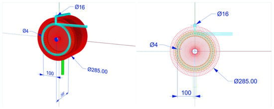
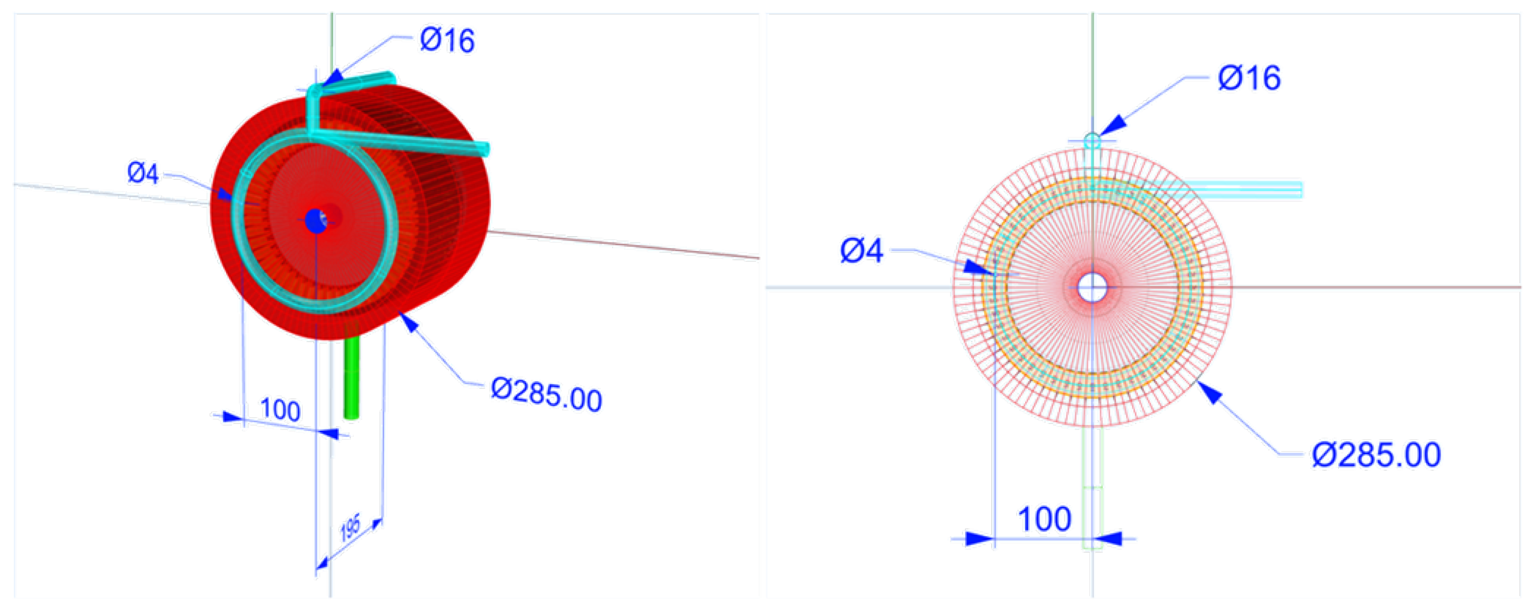
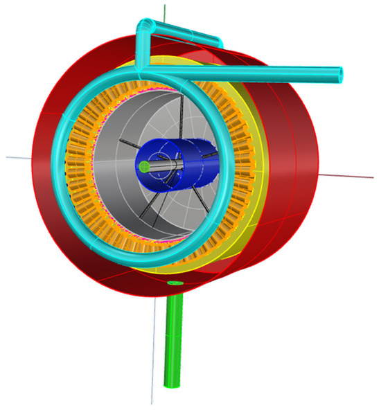
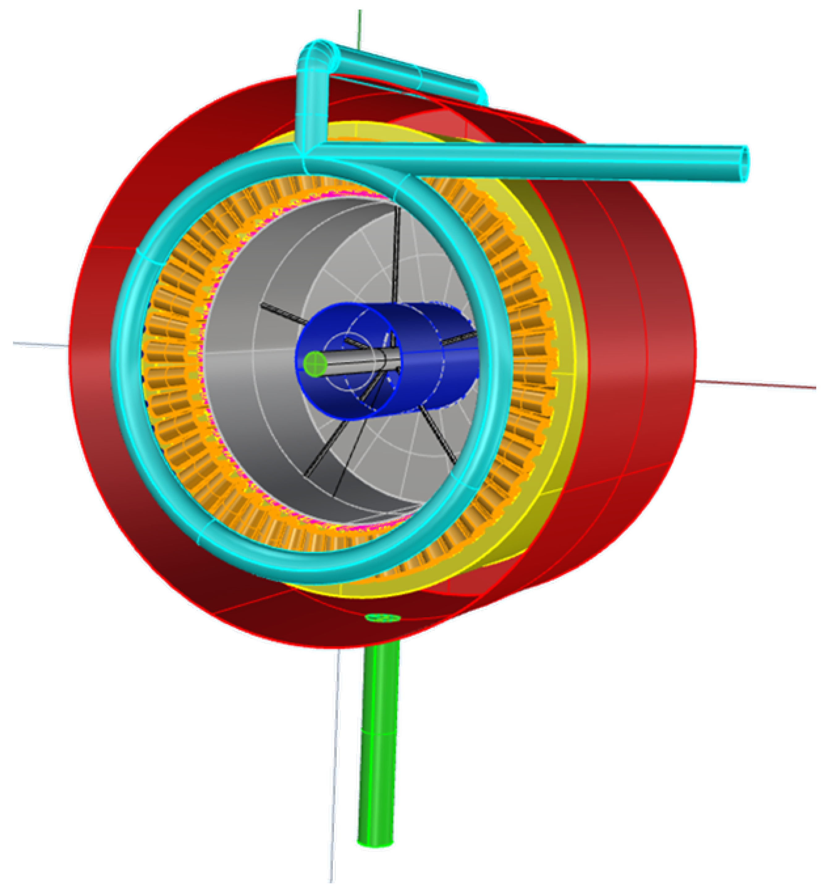
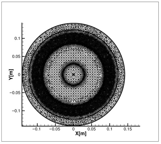
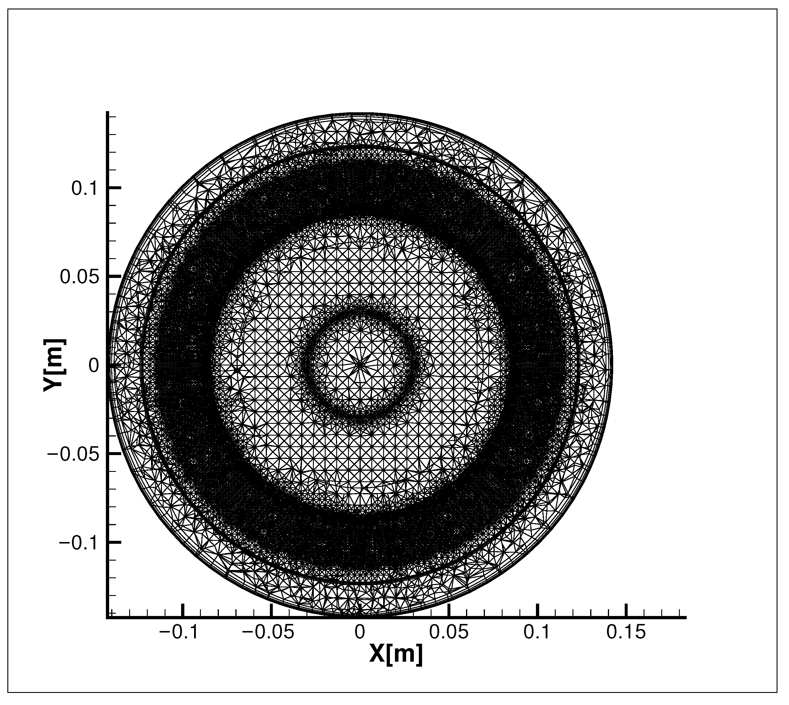
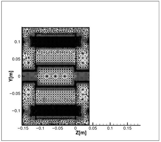
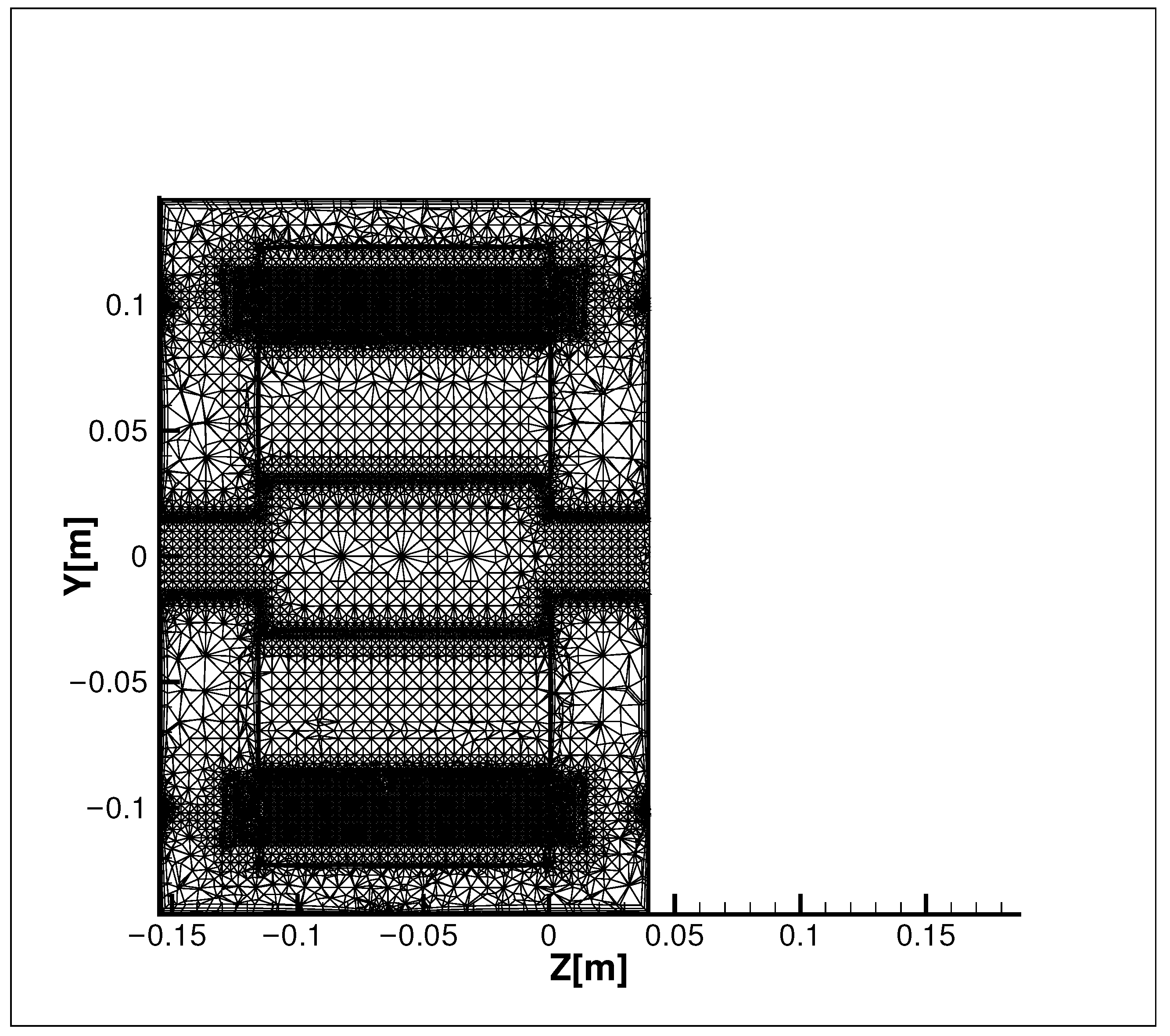
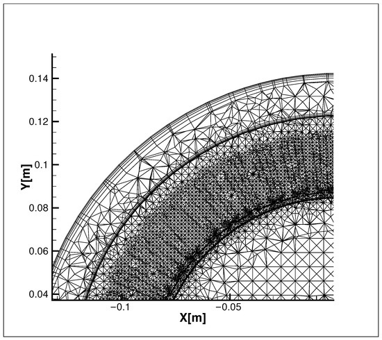
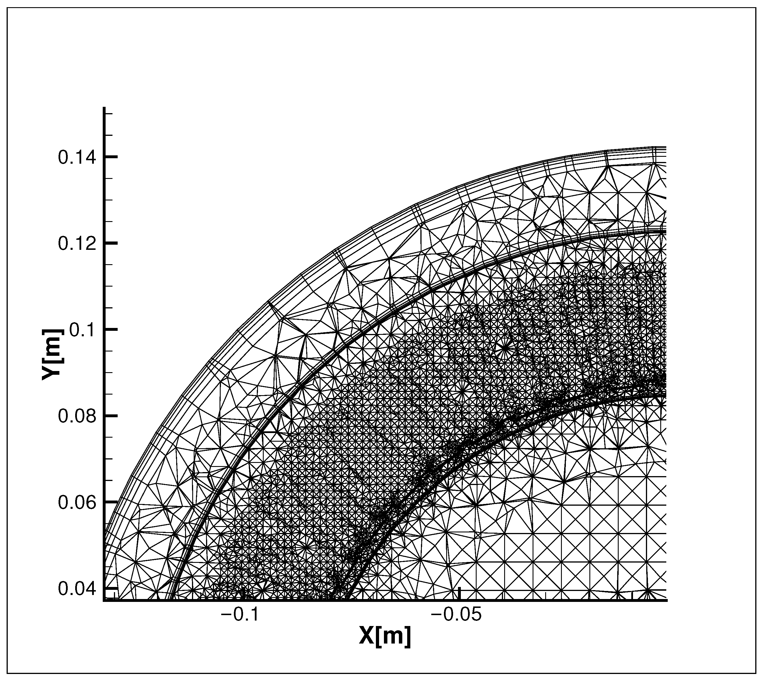
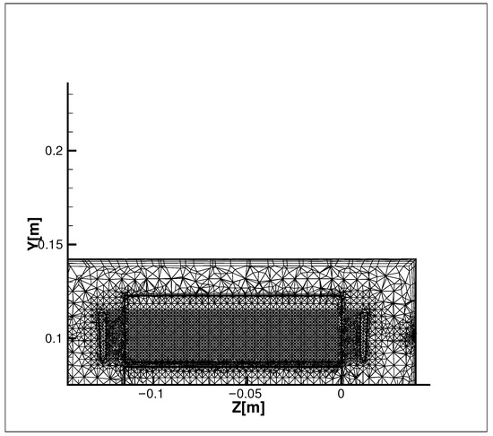
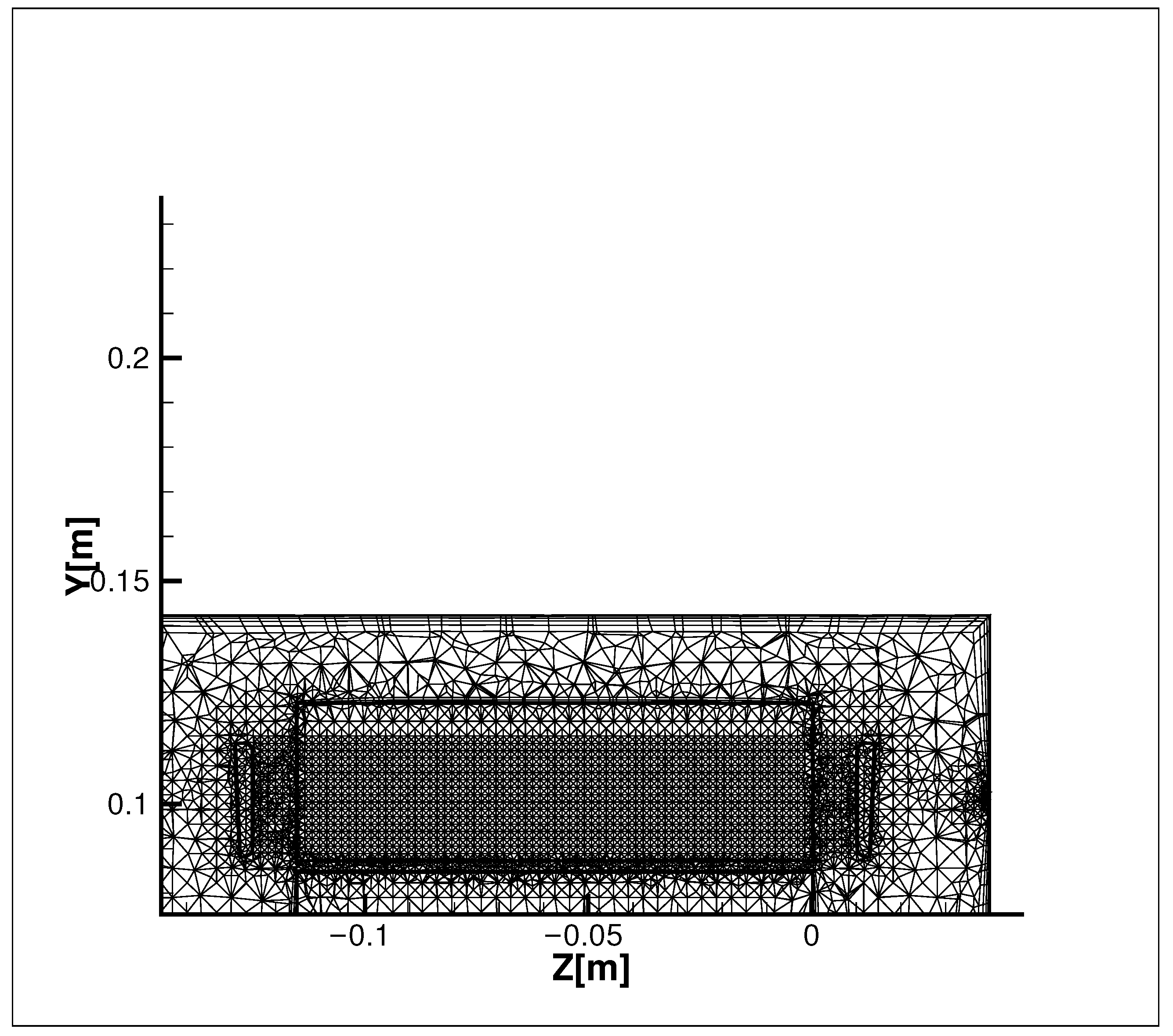
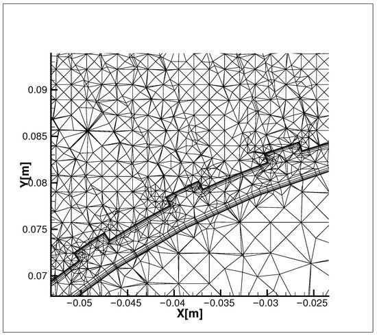
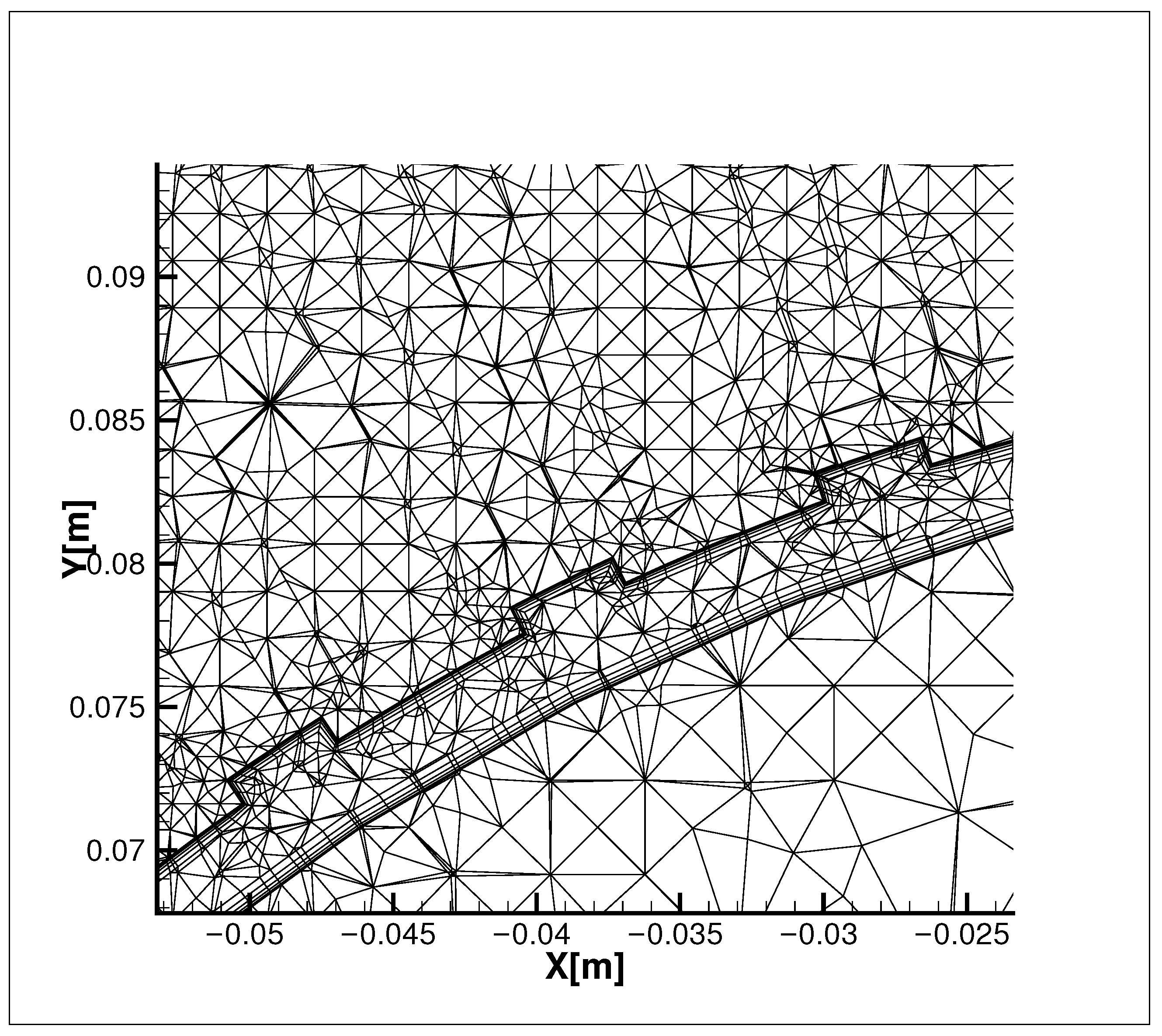
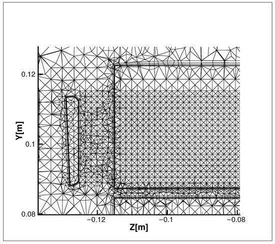
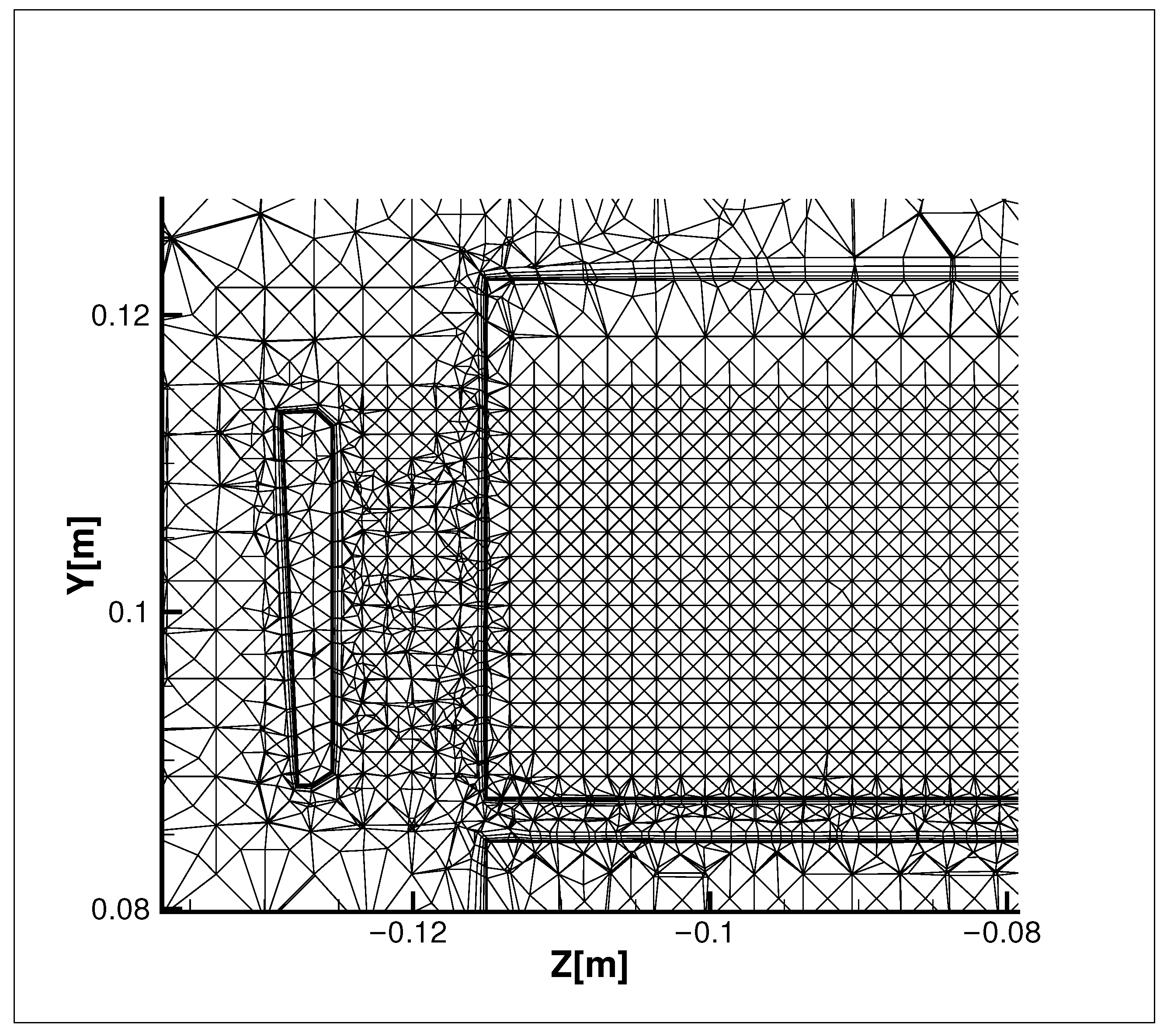
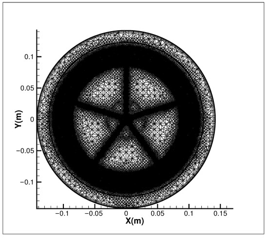
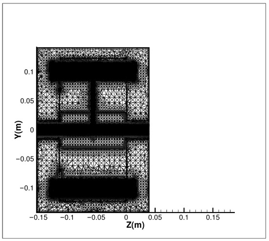
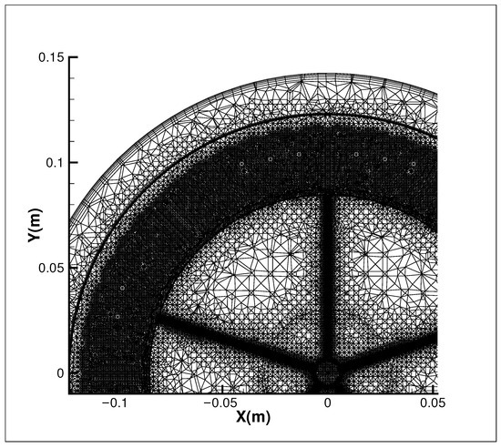
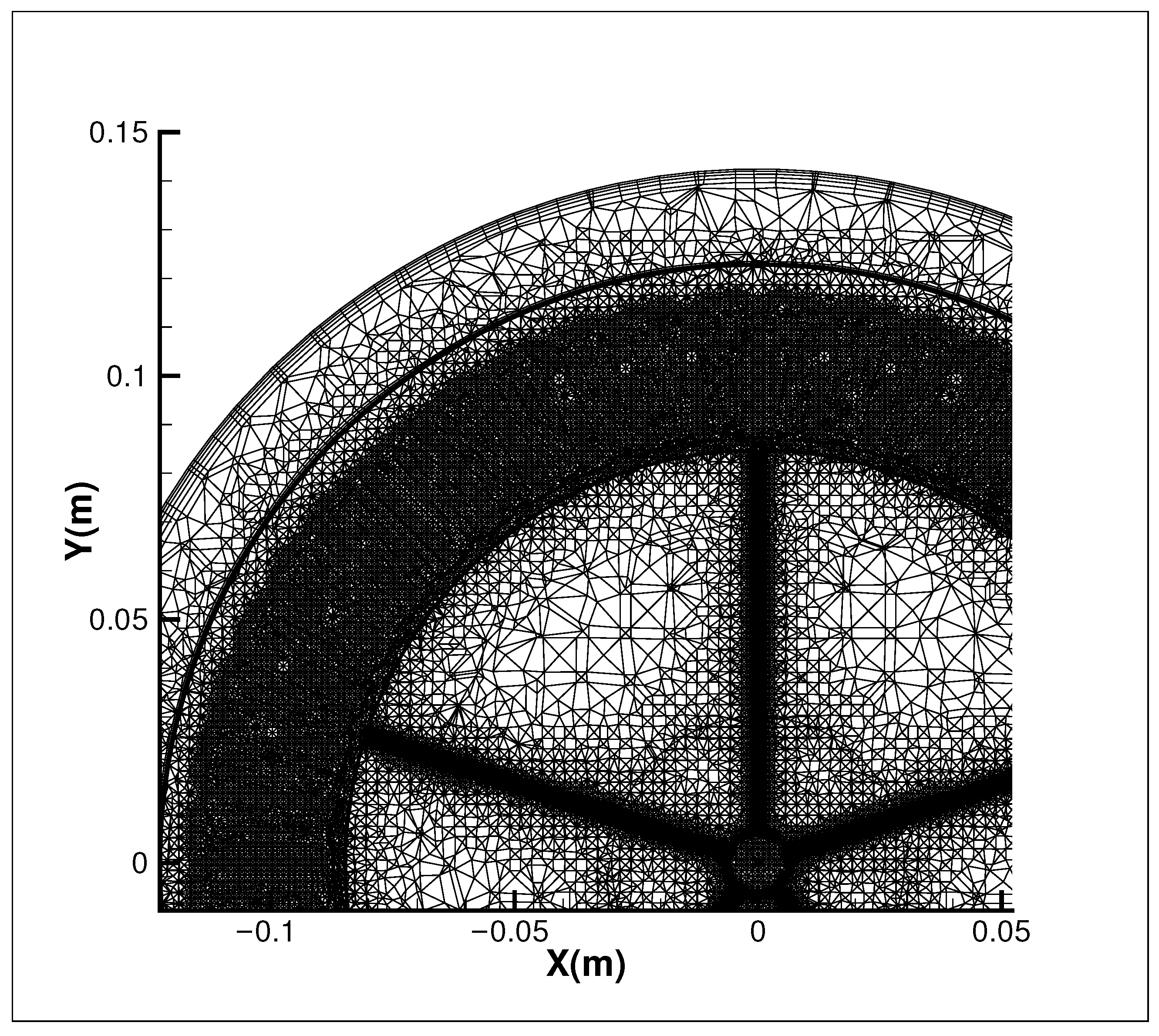
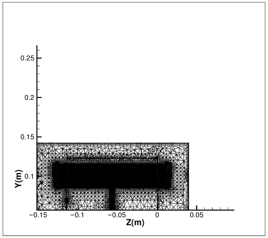
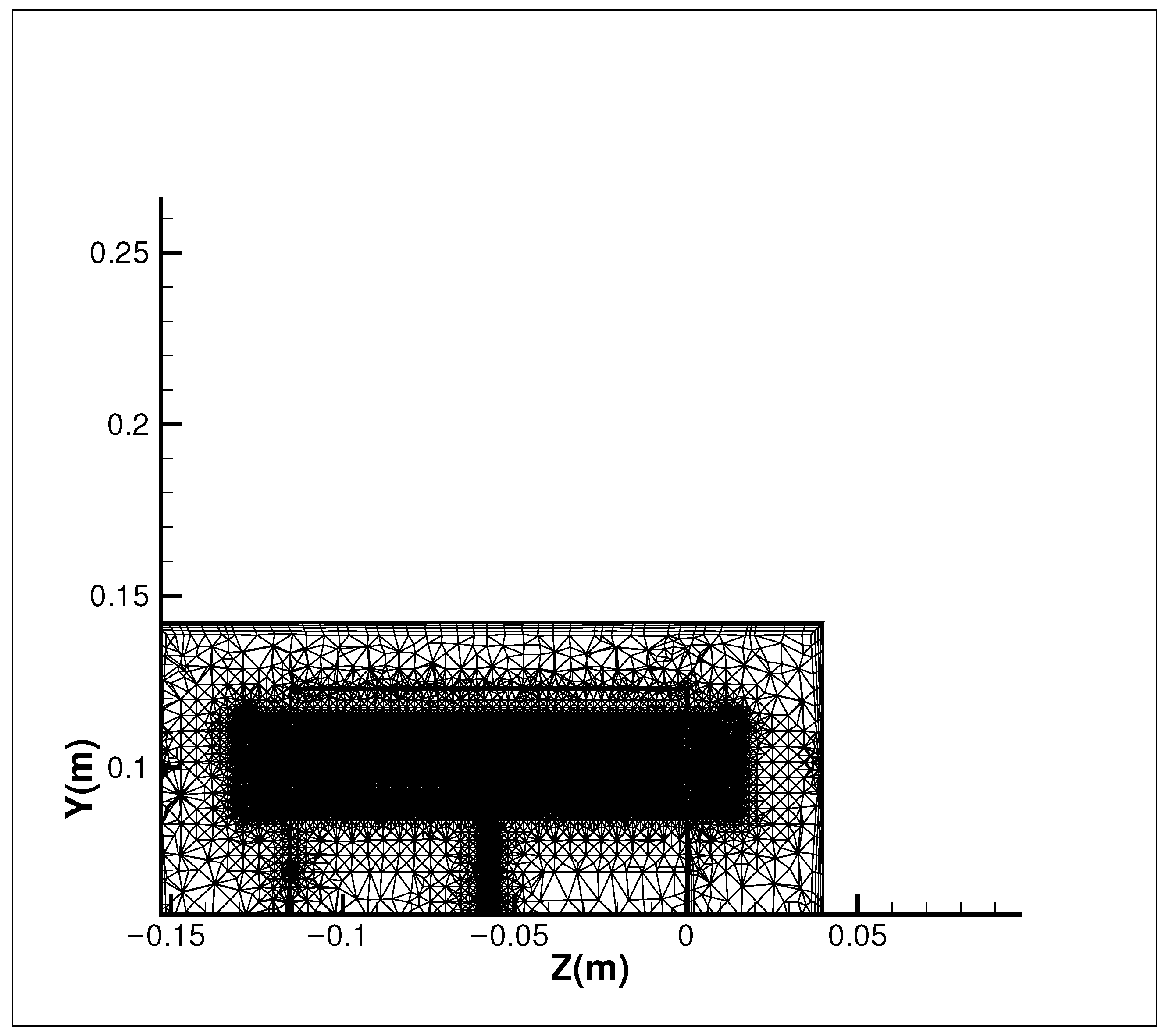
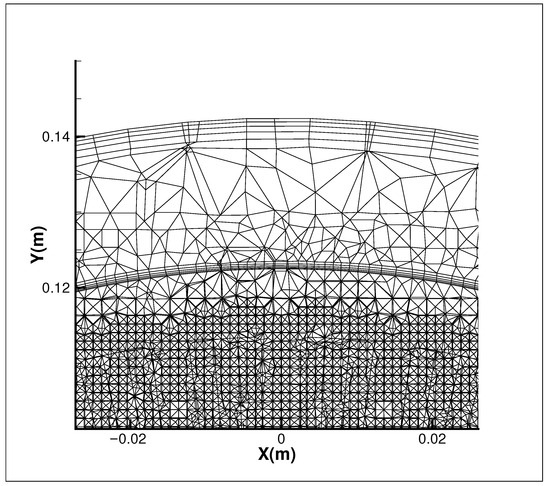
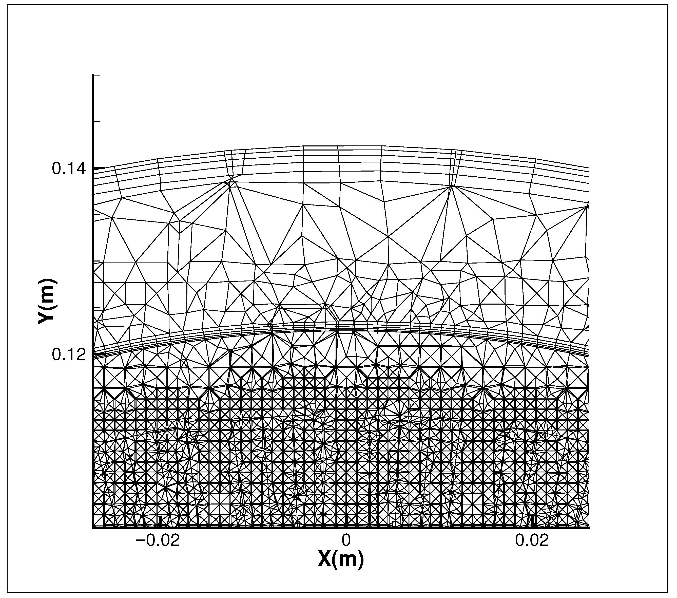
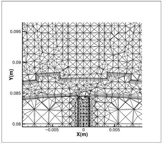
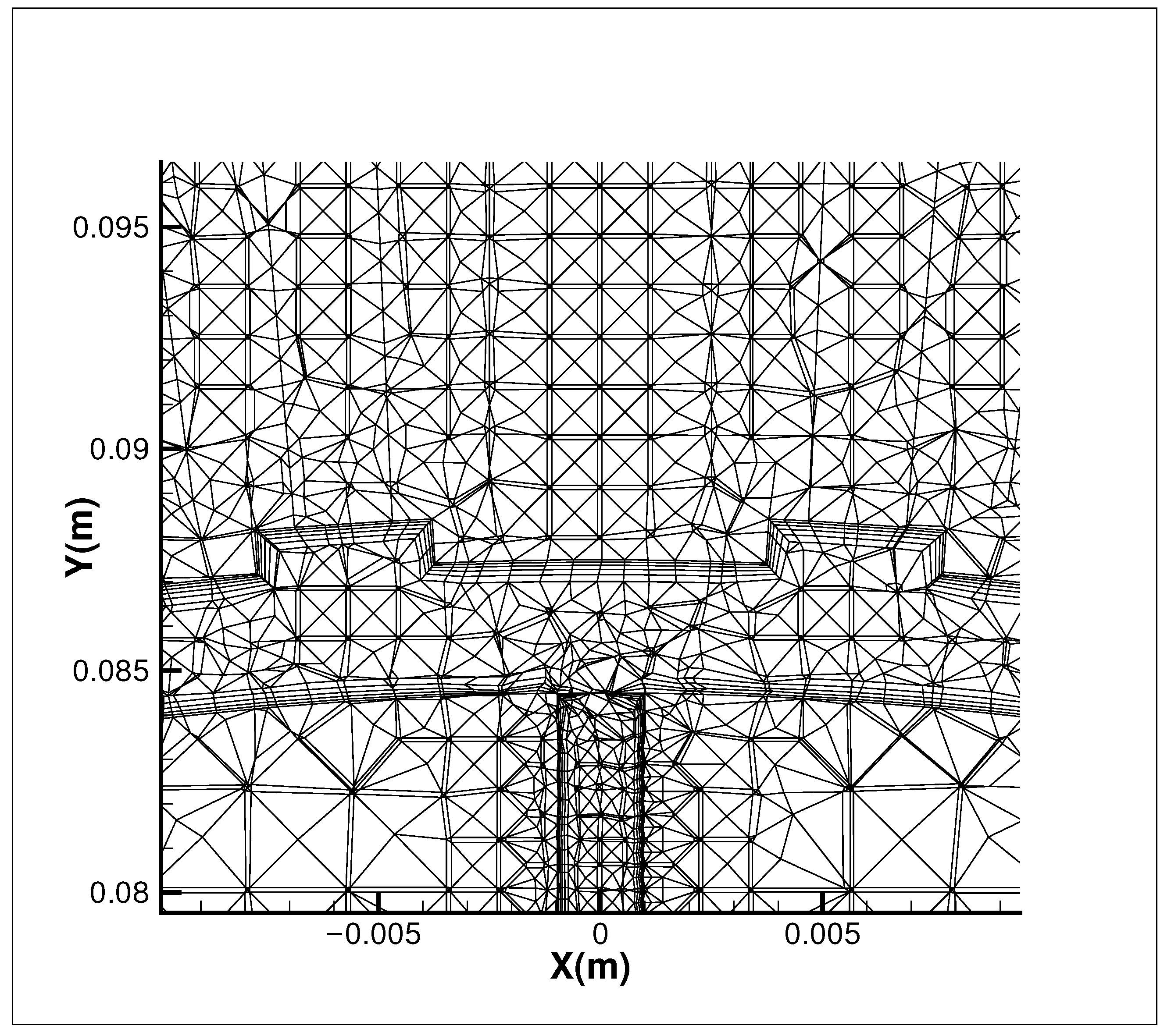
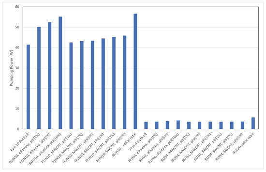
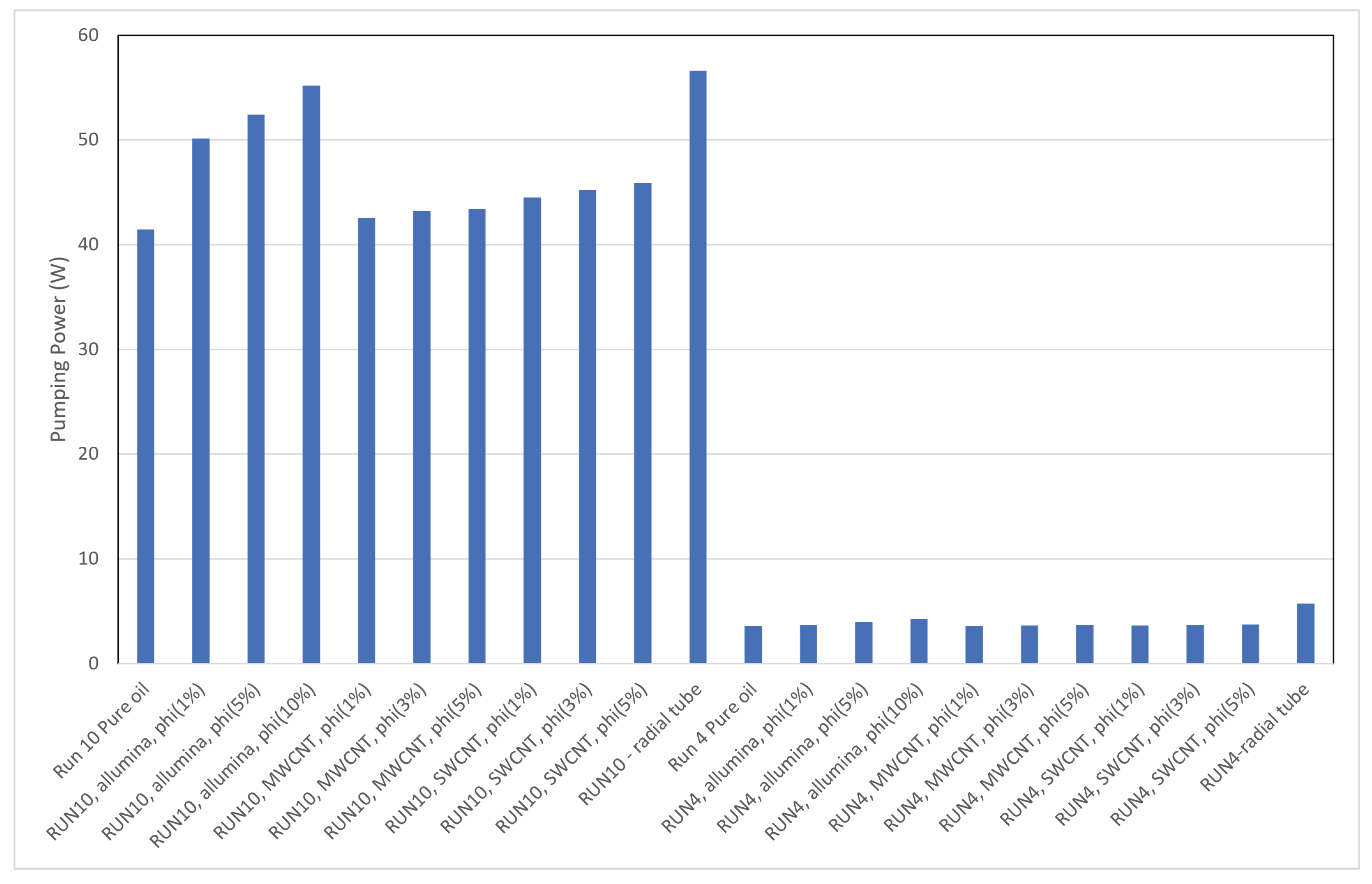
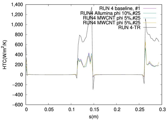
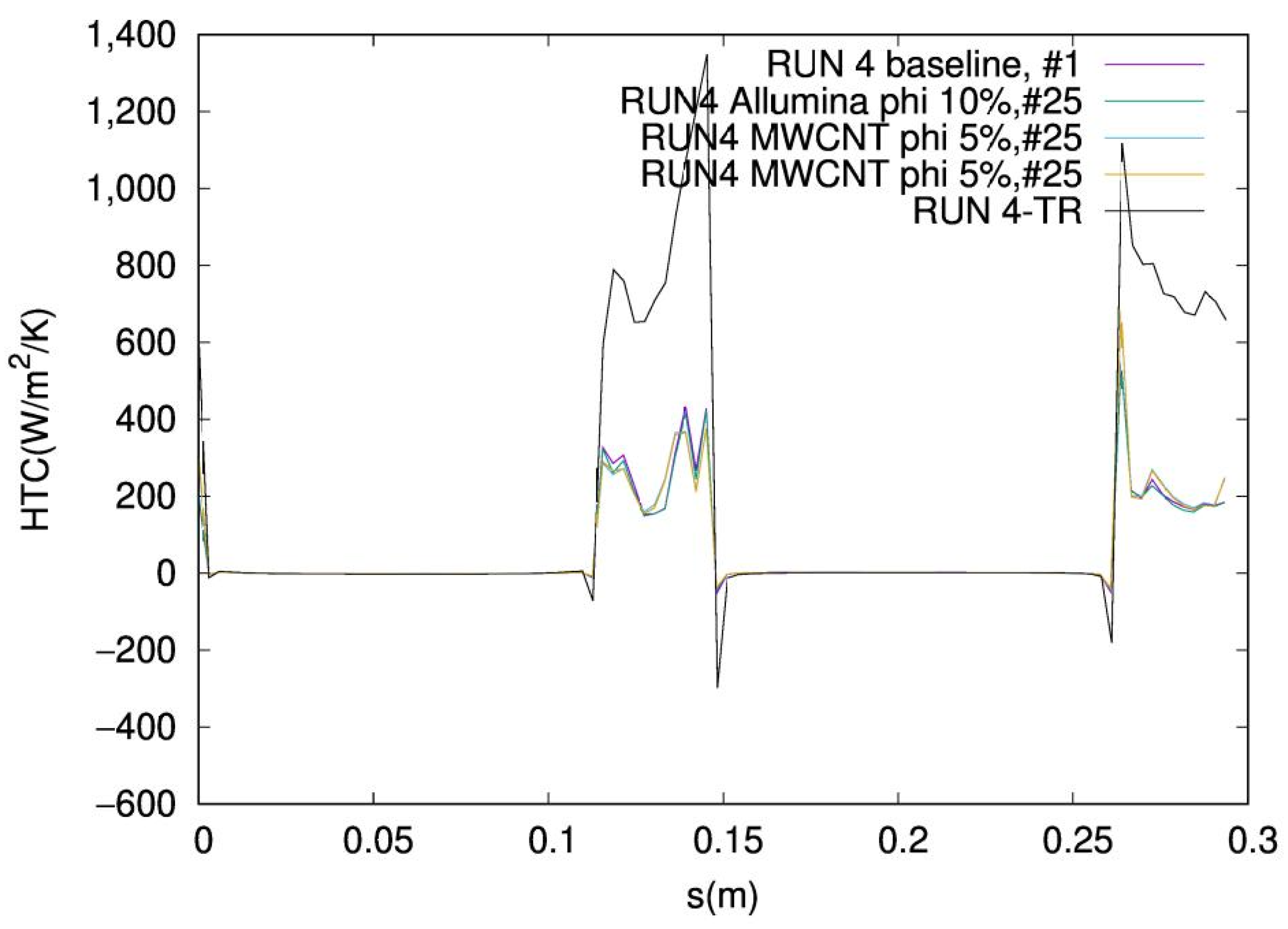
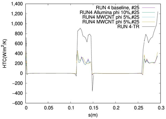
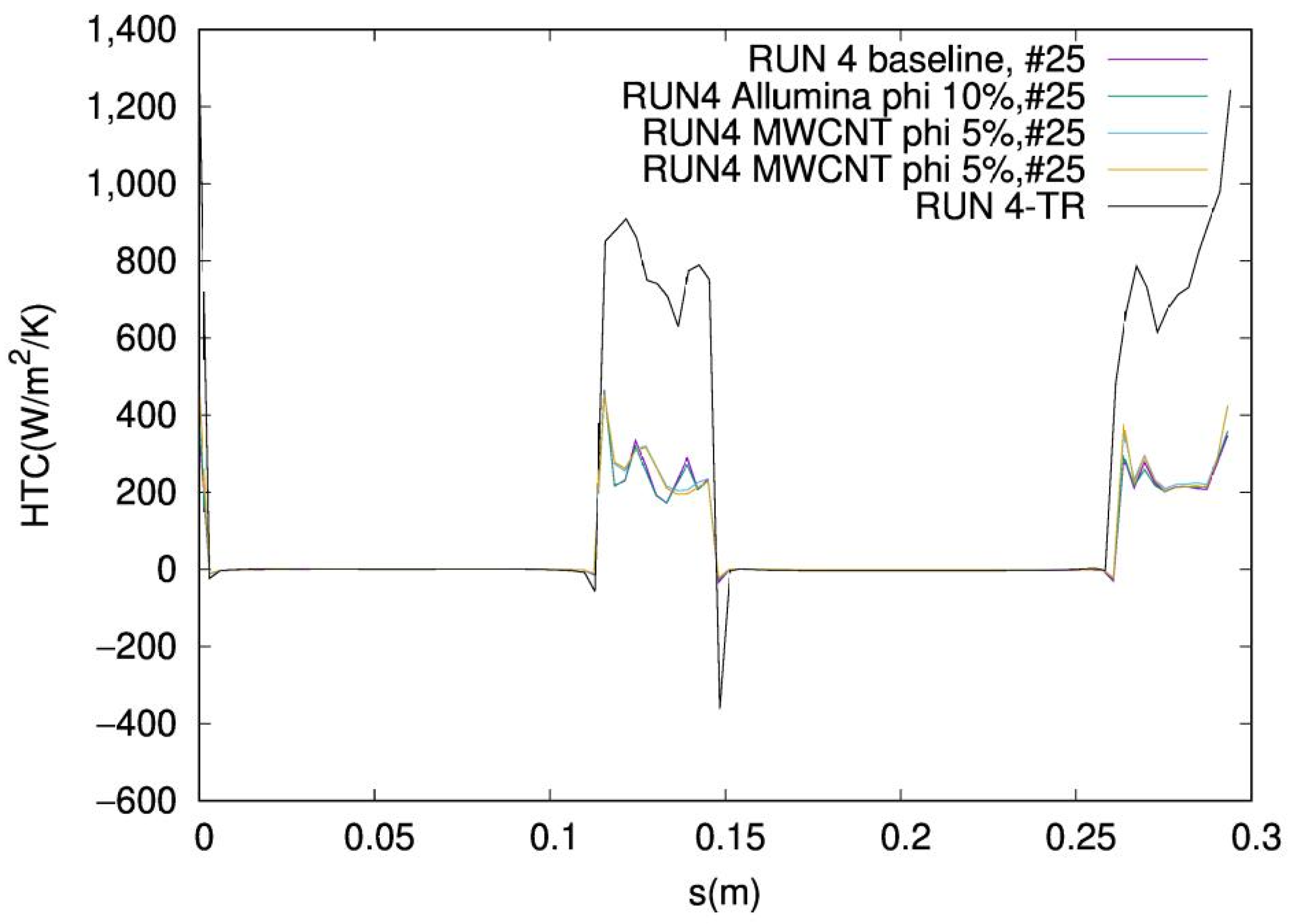
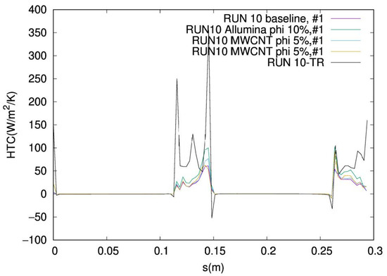
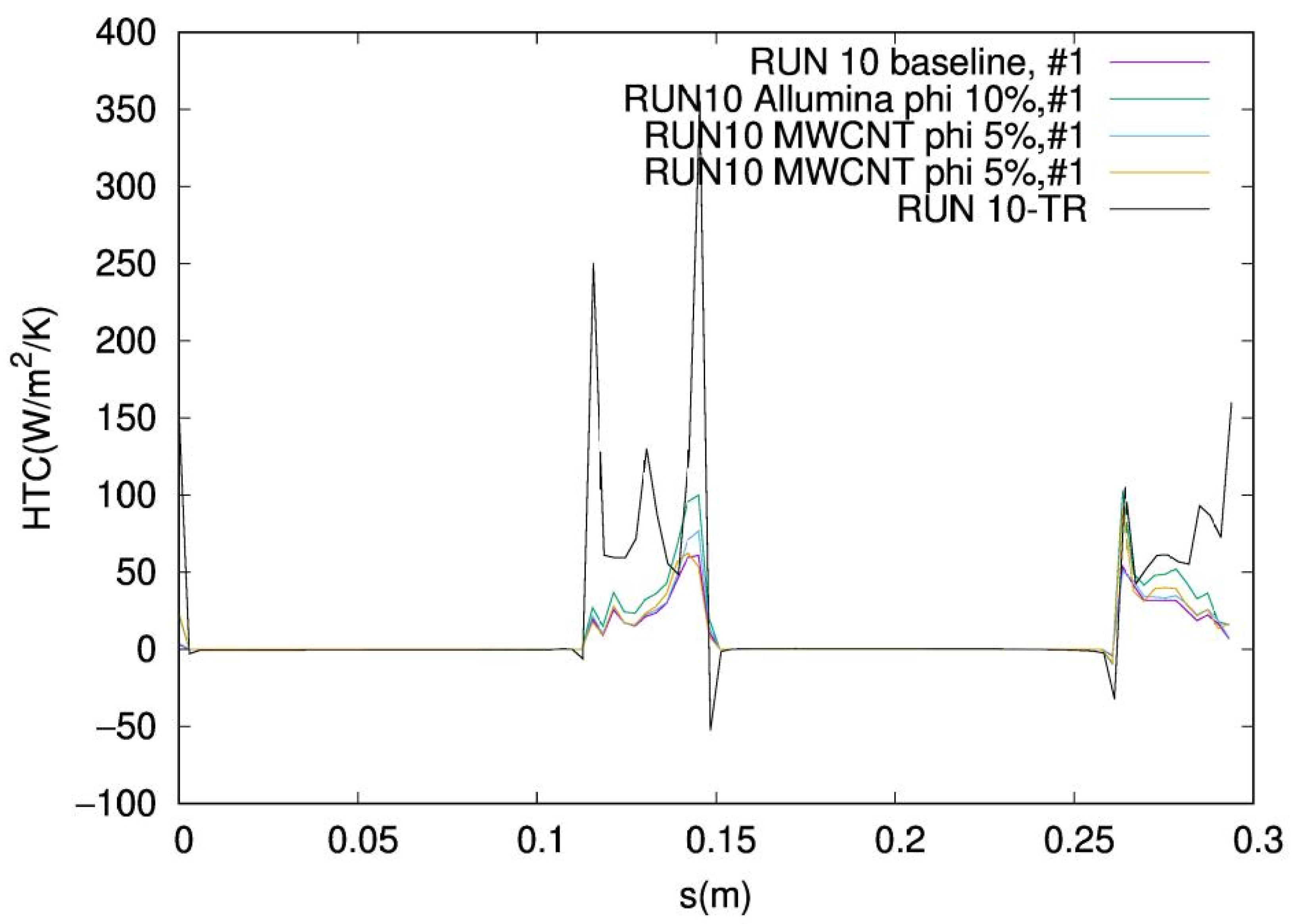
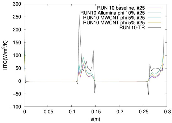
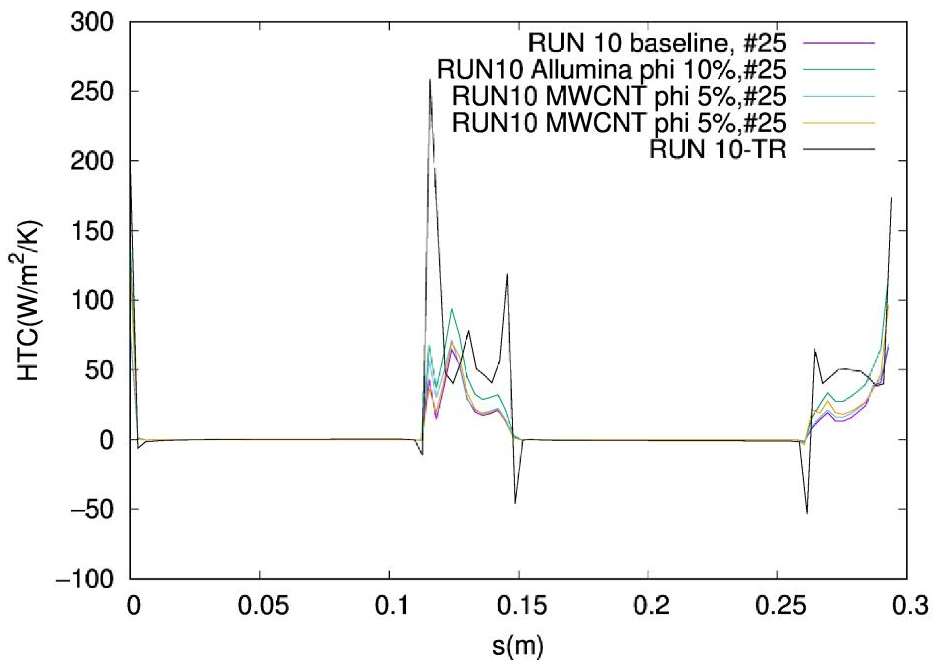
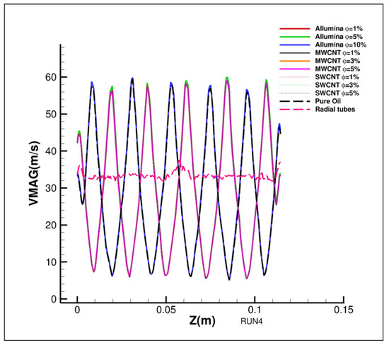
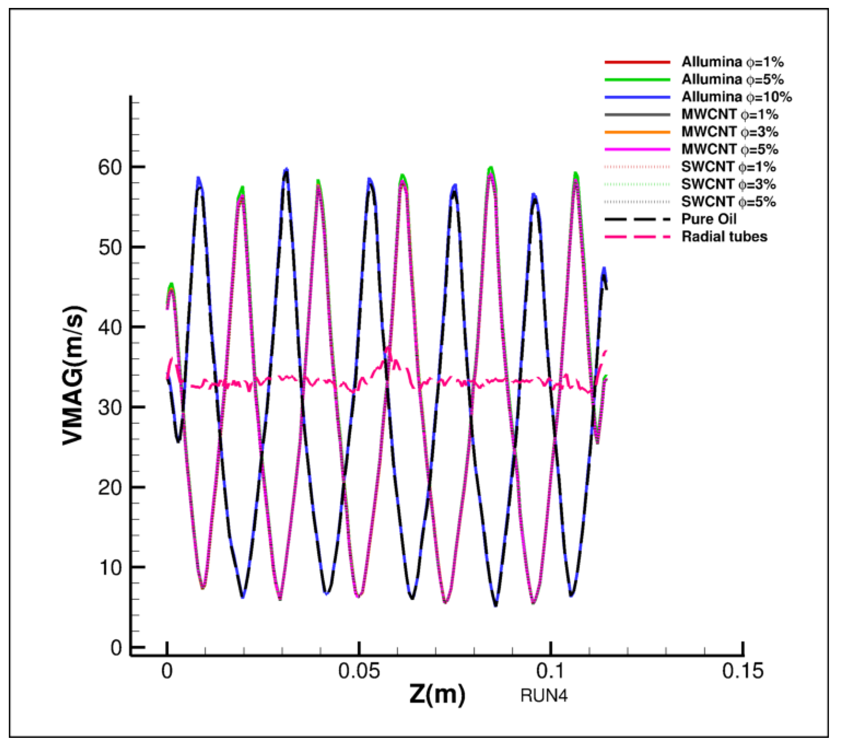
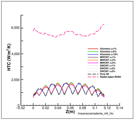
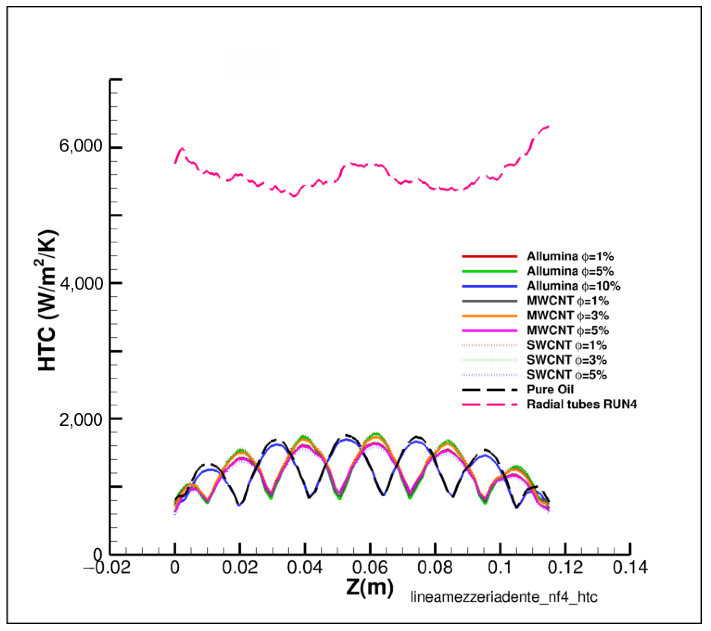
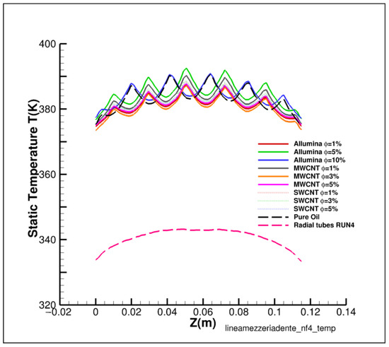
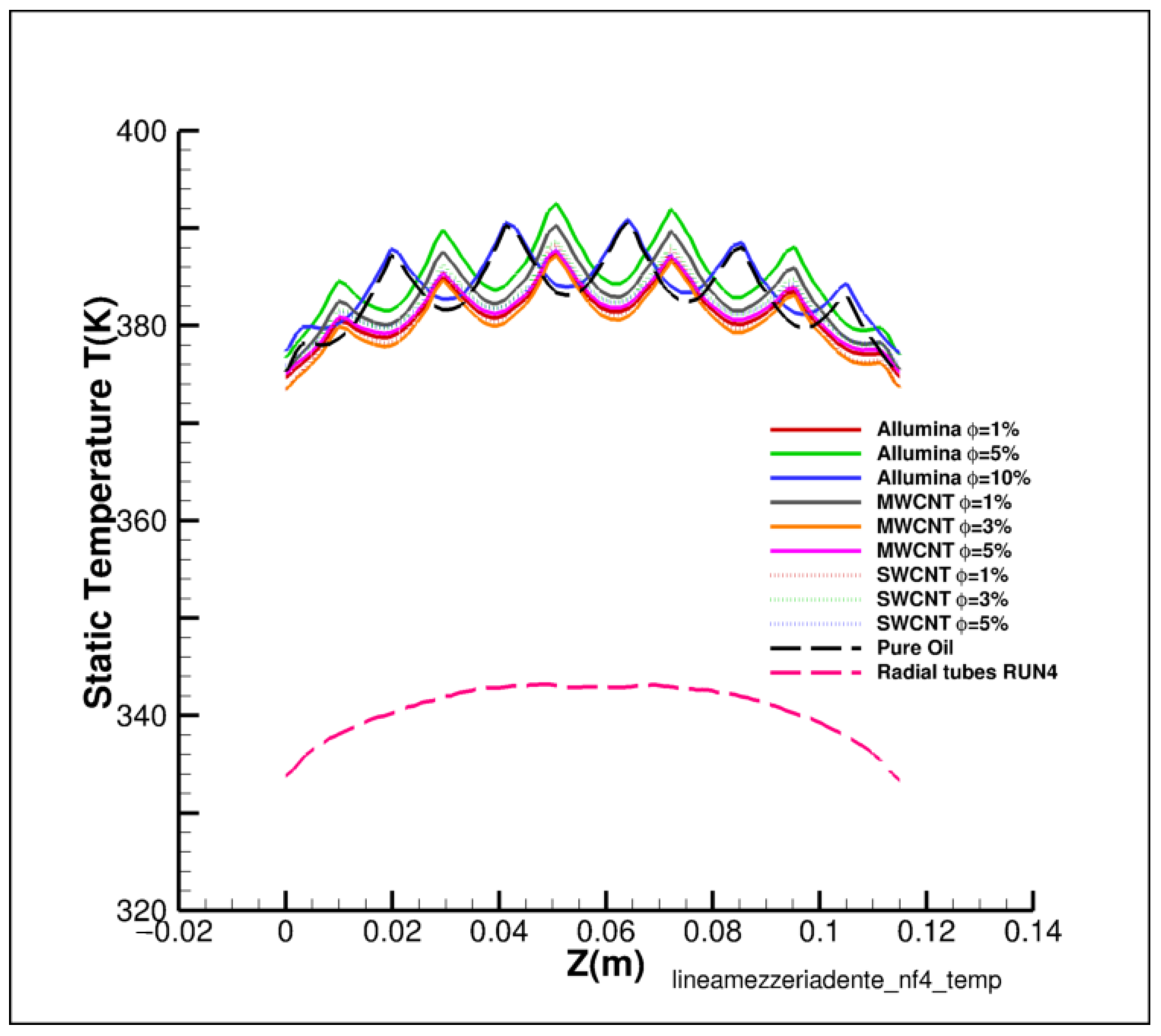
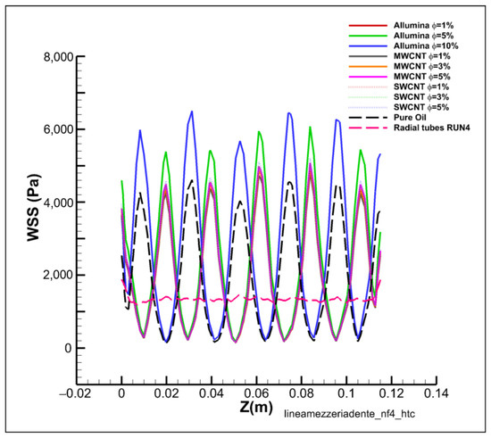
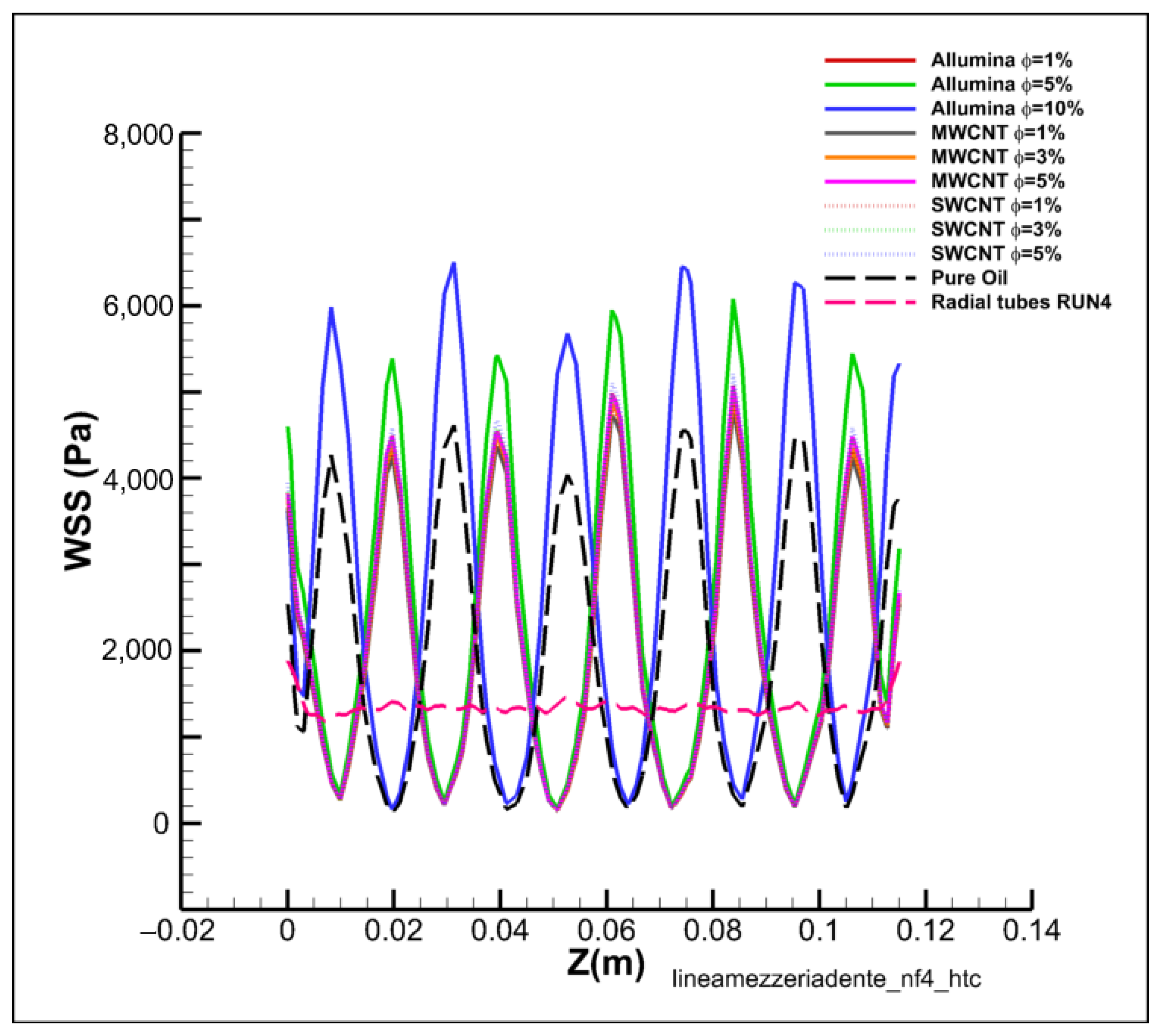
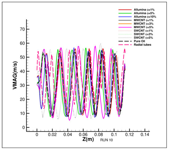
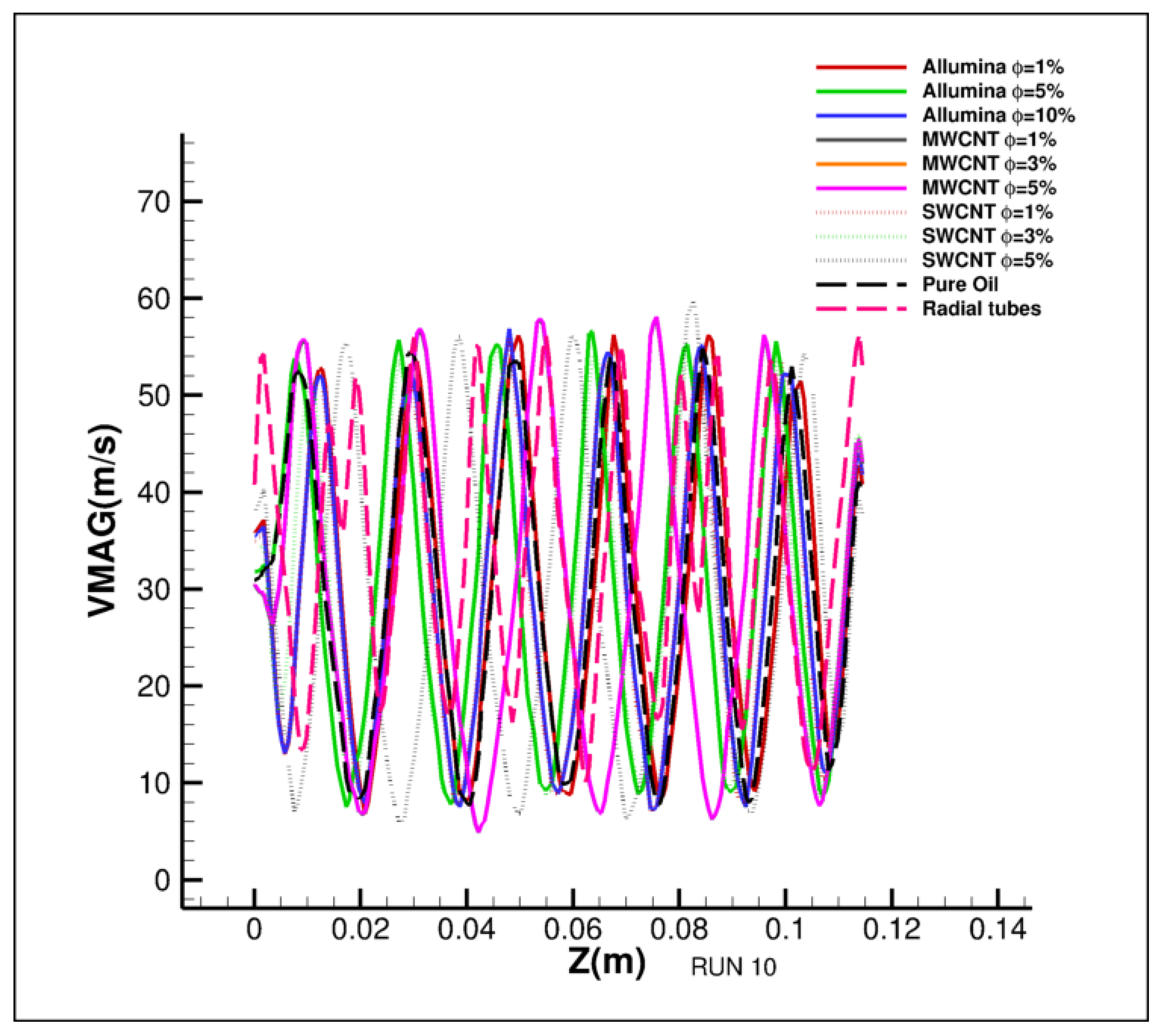
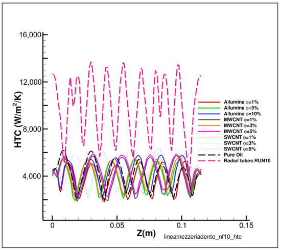
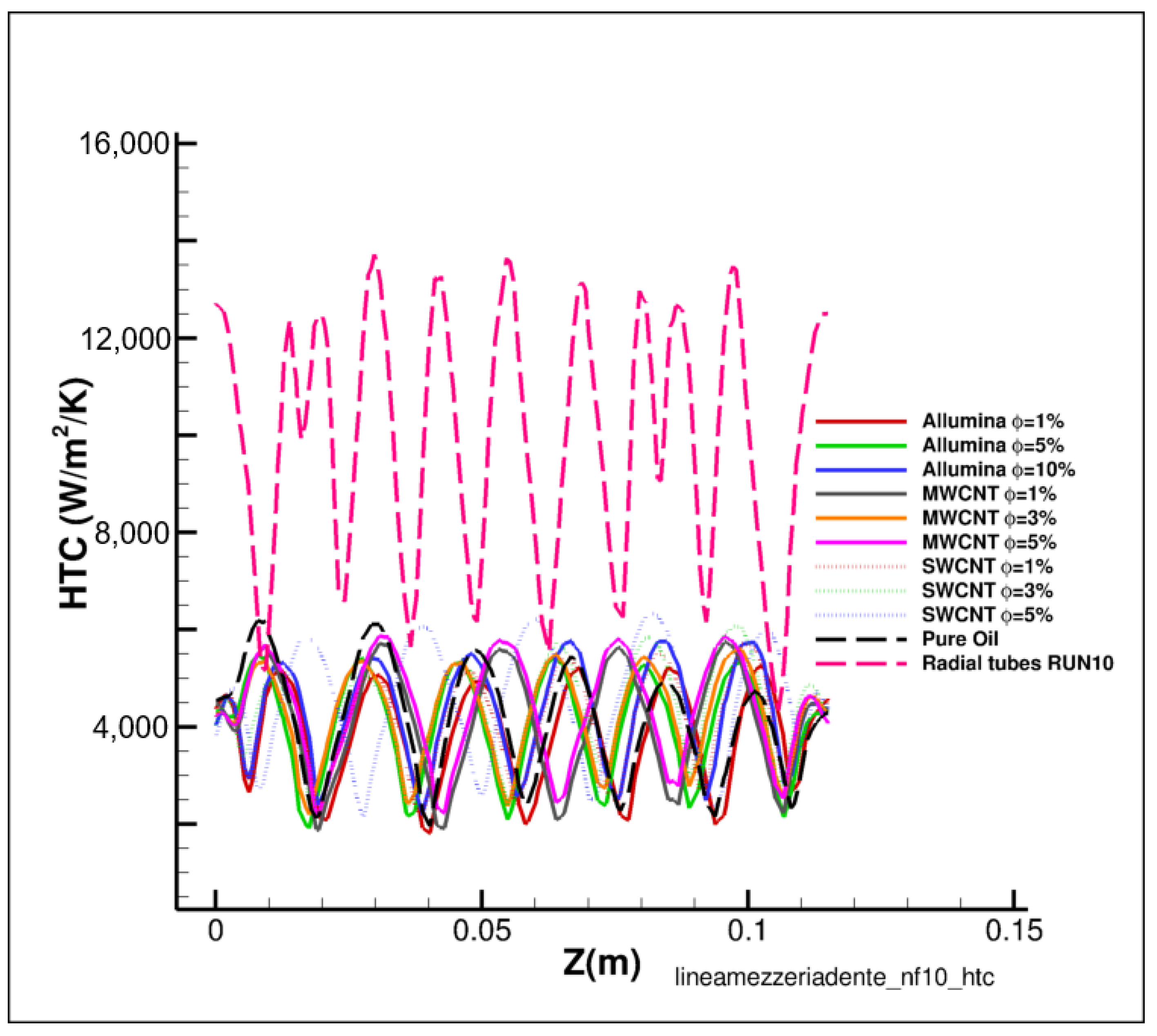
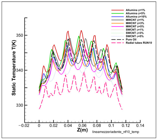
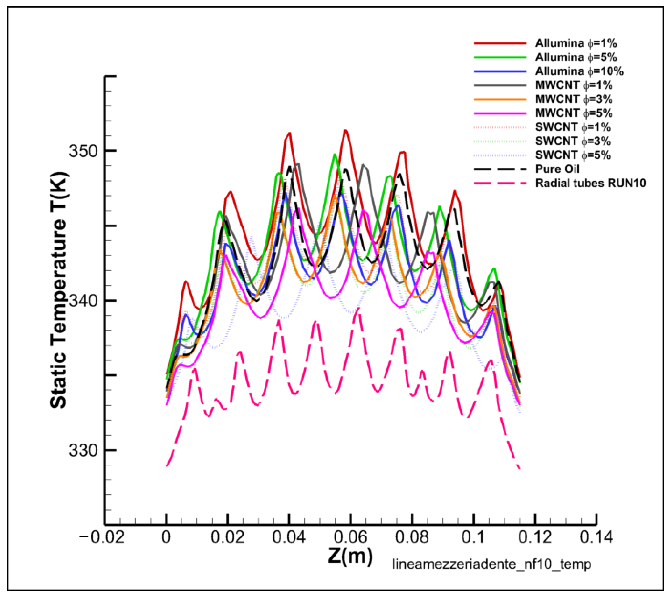
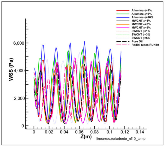
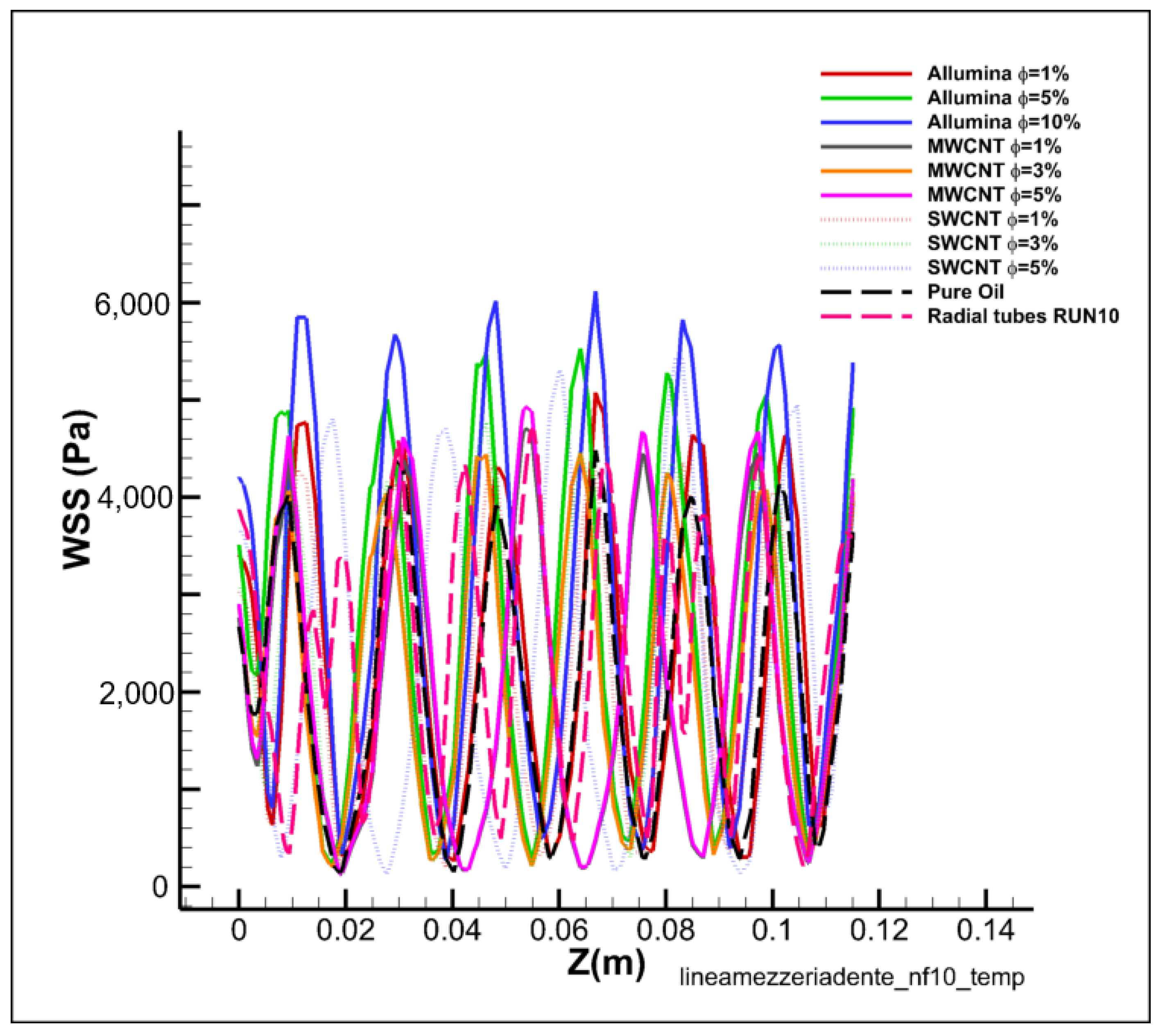
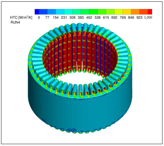
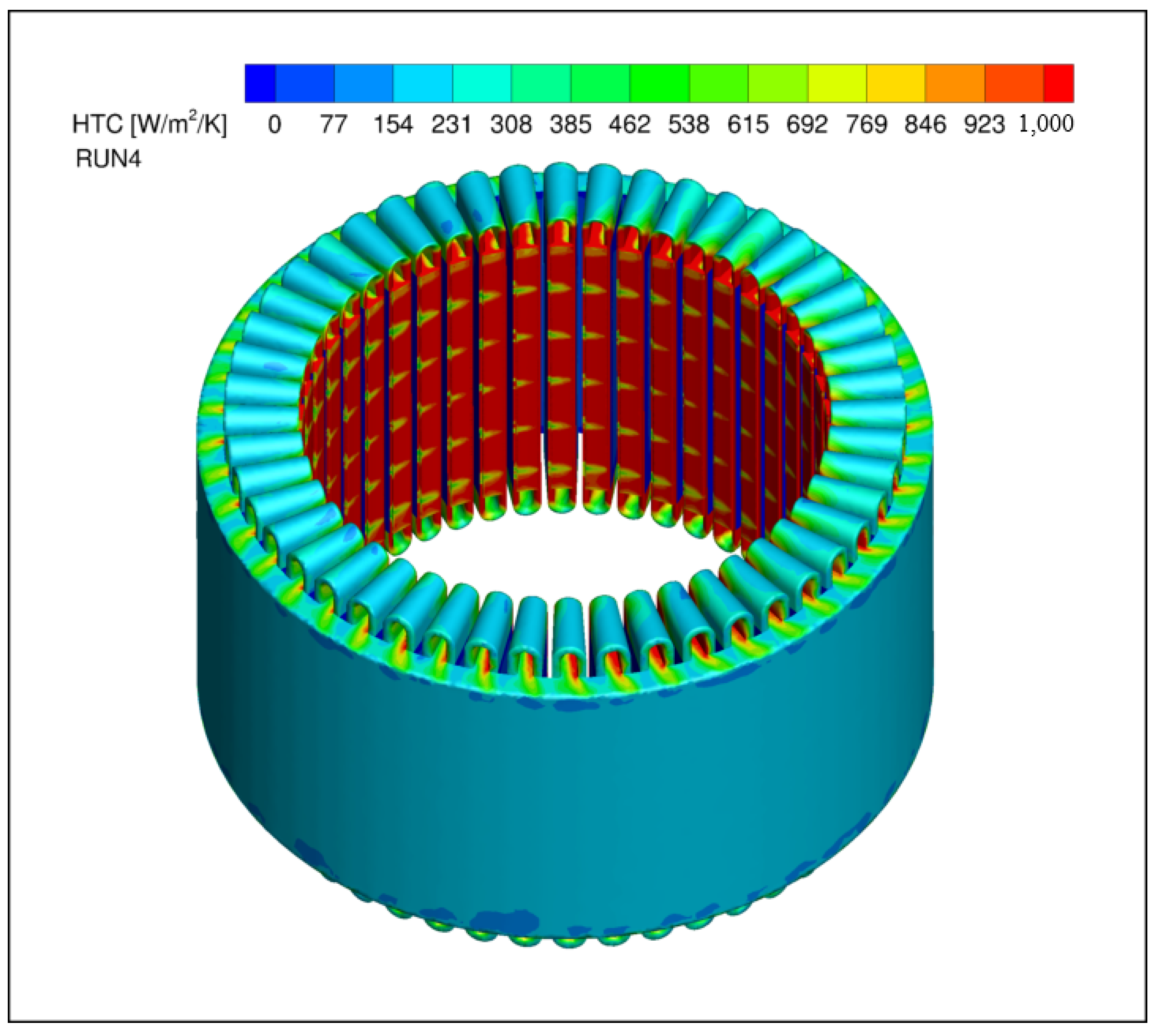
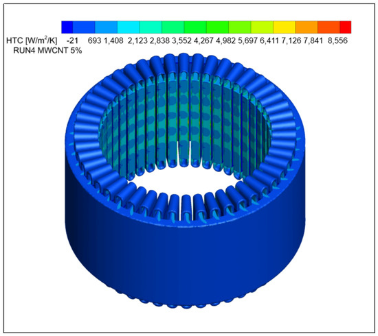
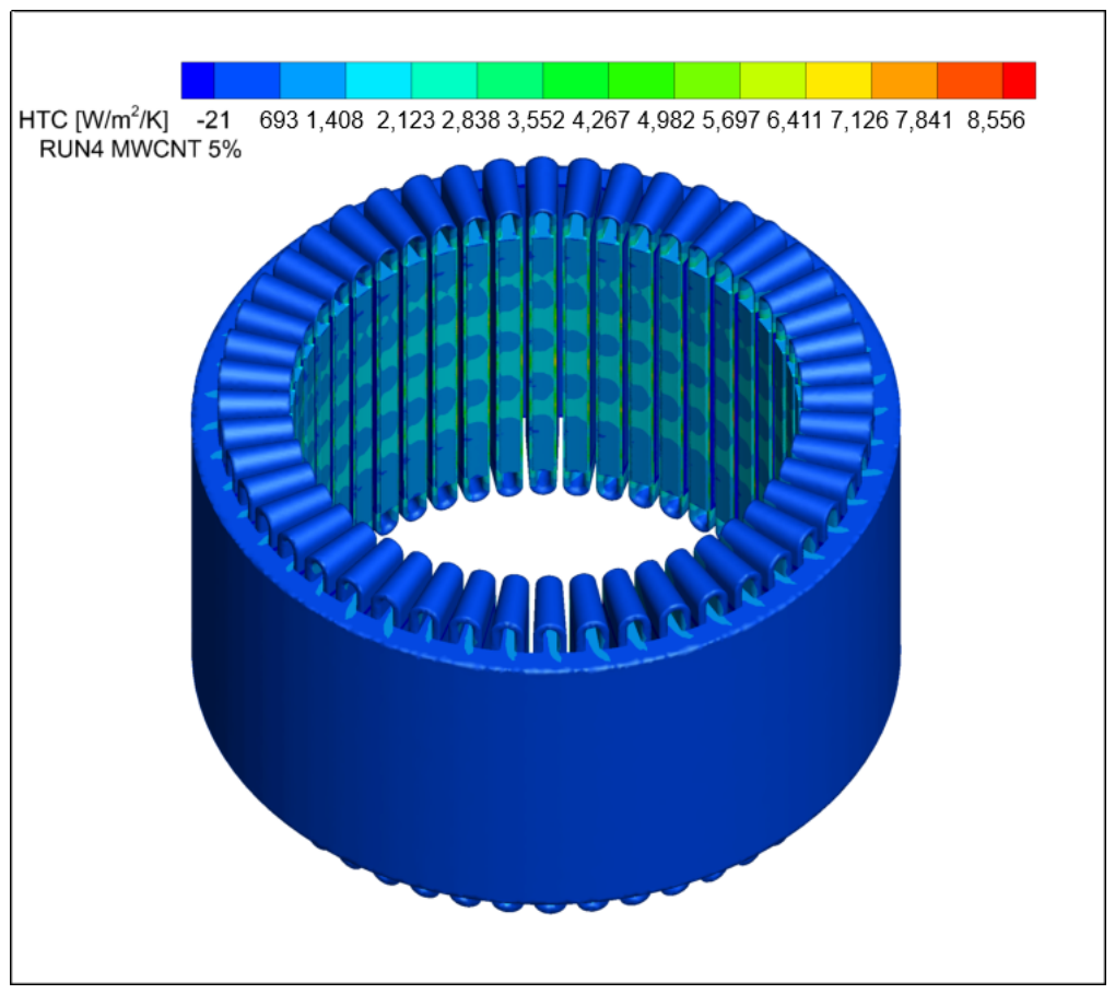
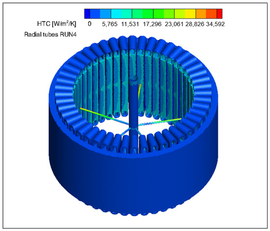
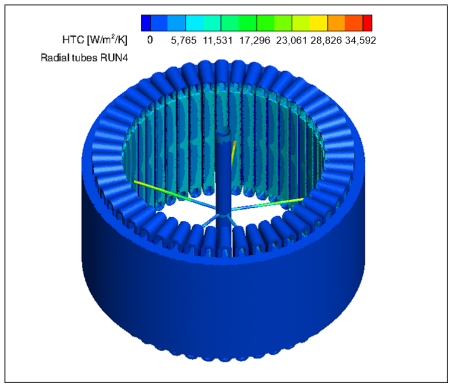
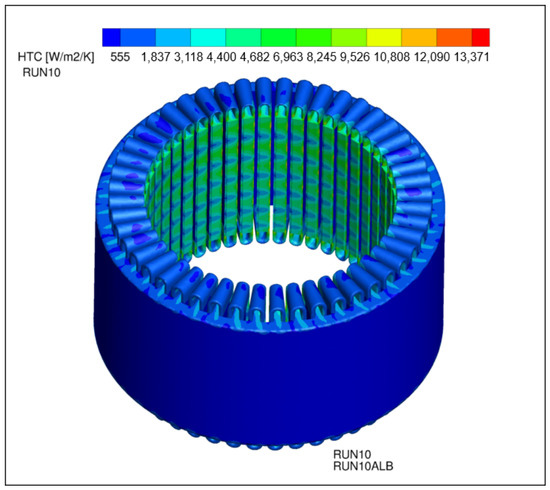
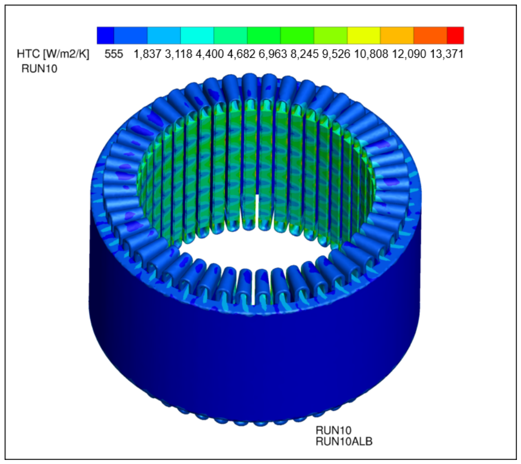
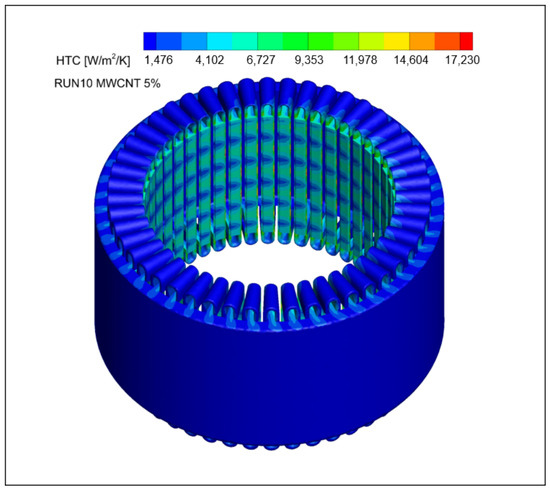
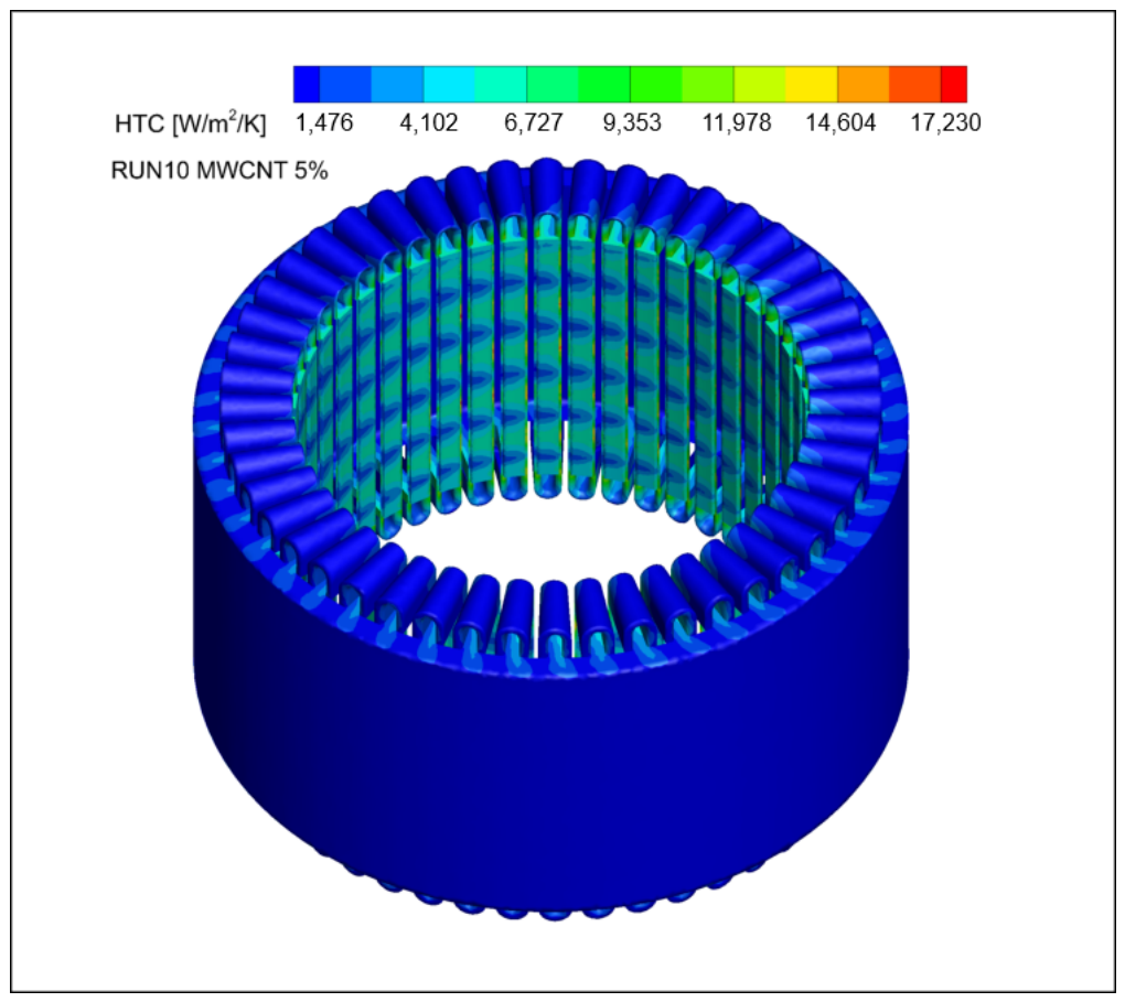
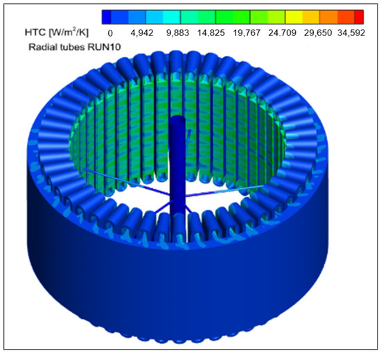
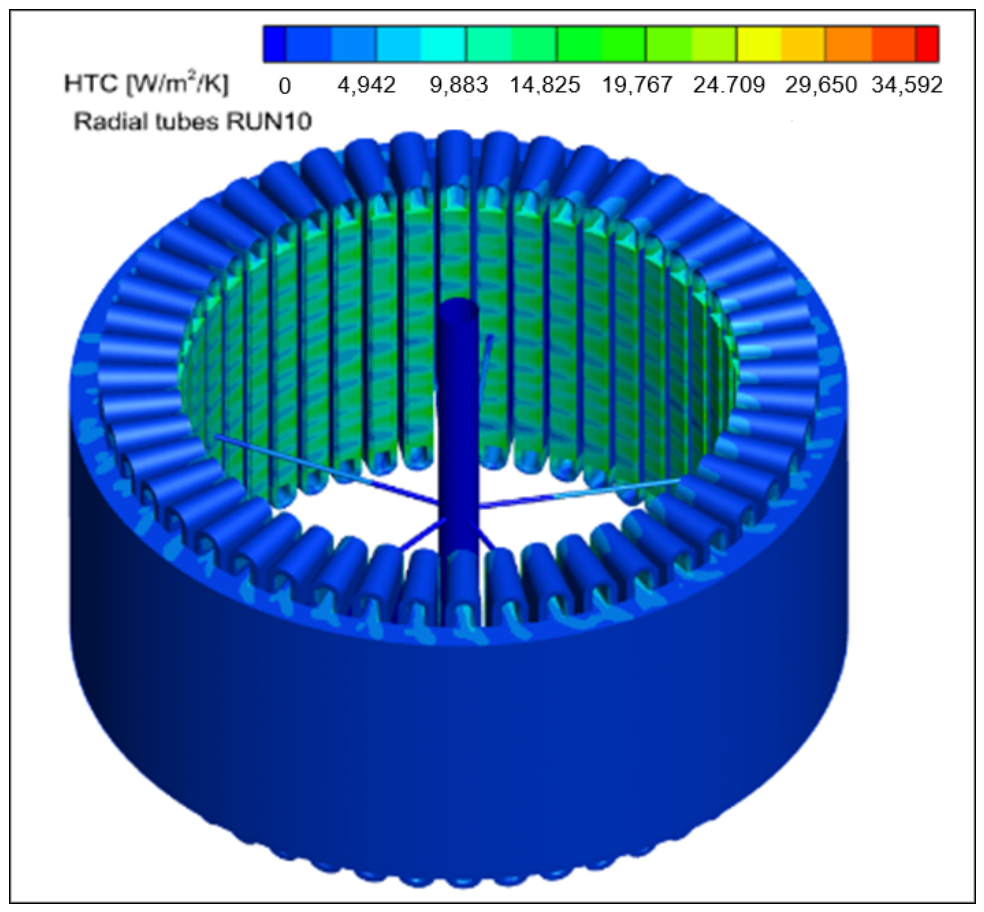
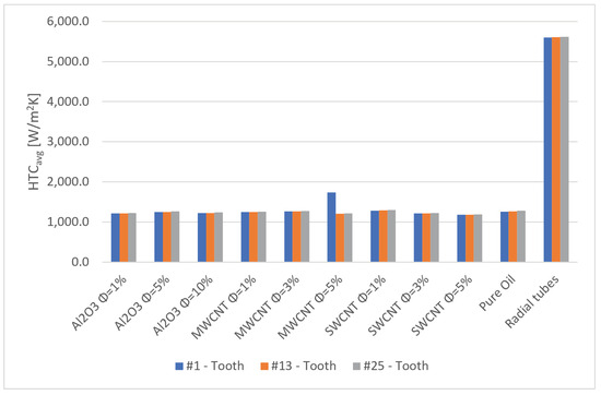
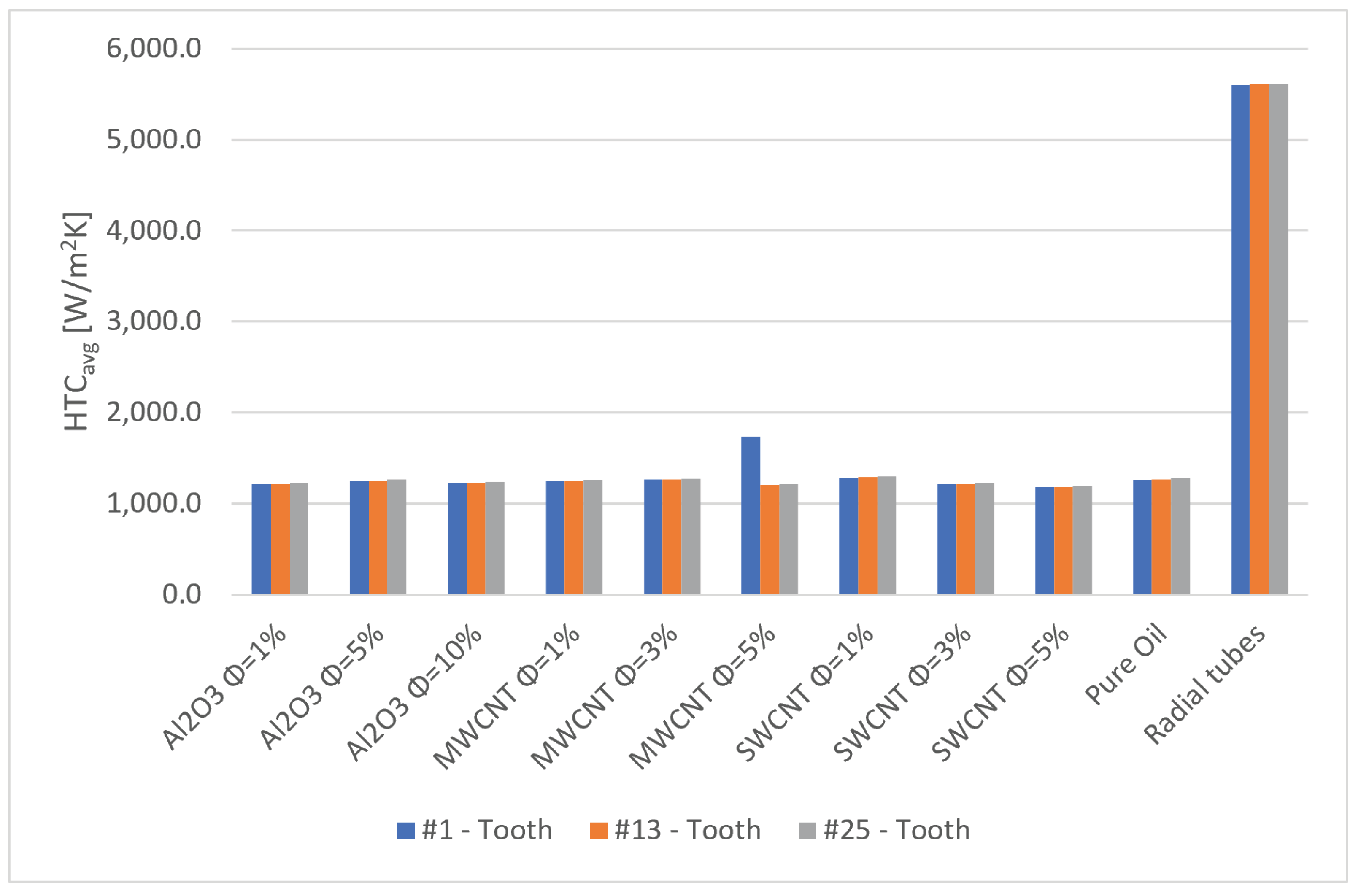
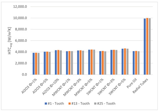
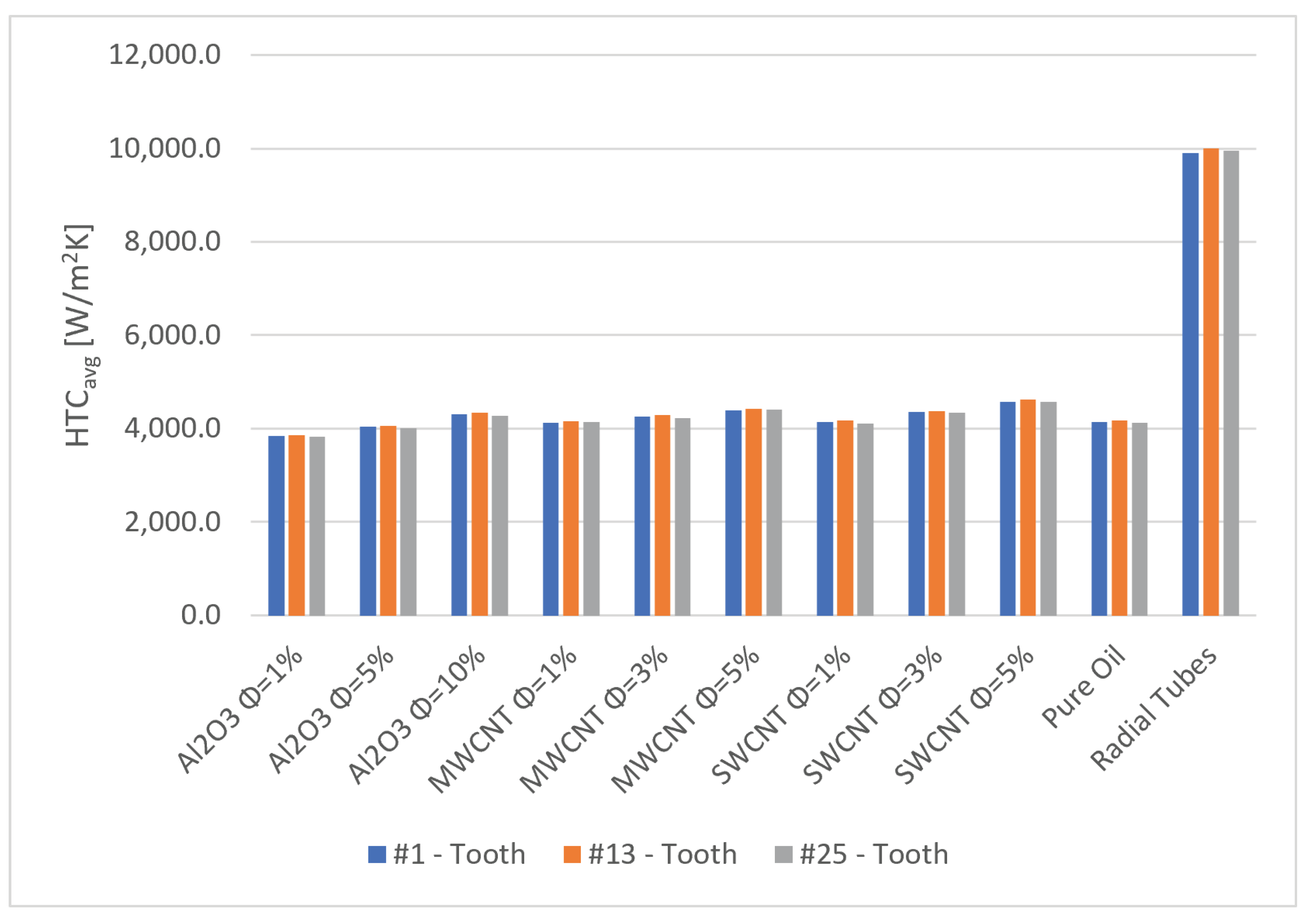

Disclaimer/Publisher’s Note: The statements, opinions and data contained in all publications are solely those of the individual author(s) and contributor(s) and not of MDPI and/or the editor(s). MDPI and/or the editor(s) disclaim responsibility for any injury to people or property resulting from any ideas, methods, instructions or products referred to in the content. |
© 2026 by the authors. Licensee MDPI, Basel, Switzerland. This article is an open access article distributed under the terms and conditions of the Creative Commons Attribution (CC BY) license.