


Abstract
This paper reports the design, implementation, and experimental evaluation of a laboratory autonomous parking platform that supports both perpendicular and parallel parking. The platform integrates three components. First, a depth-image processing pipeline comprising grayscale conversion, Gaussian filtering, Canny edge detection, and Hough transform line extraction is used for parking space detection, together with a pixel-width criterion for distinguishing perpendicular from parallel spaces. Second, a turning-radius trajectory planning strategy based on Ackermann steering geometry determines the steering positions for each parking mode. Third, a fuzzy correction scheme, using membership functions for lateral position and heading angle estimated from web camera imagery, refines the final parking pose. Throughout all maneuvers, LiDAR provides 360° environmental scanning for obstacle detection and emergency stop. Seven test cases covering all supported parking modes were carried out; the parking mode was selected correctly and the maneuver was completed in all seven cases. The evaluation is qualitative, and the design parameters reported here are specific to the hardware configuration used. The contribution is accordingly a transparent and fully documented reference implementation rather than a performance advance.
1. Introduction
The rapid advancement of intelligent transportation technologies has profoundly transformed modern mobility. Autonomous vehicles, in particular, offer a promising solution to enhance safety, efficiency, and convenience in daily travel. By integrating advanced perception systems, decision-making algorithms, and control strategies, self-driving cars reduce reliance on human drivers, thereby minimizing human error and improving overall traffic flow. Beyond navigation, these systems provide passengers with greater comfort, enabling them to rest or engage in other activities without continuously monitoring road conditions.
Despite these advances, parking remains one of the most challenging aspects of autonomous driving. Parking maneuvers—particularly parallel roadside parking and perpendicular lot parking—demand precise spatial awareness and careful trajectory planning. In dense urban environments, limited space and the presence of pedestrians or nearby vehicles further complicate the process. Human drivers frequently struggle with these maneuvers, leading to inefficient parking space utilization, traffic congestion, and increased collision risk. Consequently, developing intelligent self-parking systems has become an essential research focus to automate parking while ensuring safety and efficiency [1,2,3,4,5,6,7].
Existing approaches to autonomous parking span a wide spectrum. At one end, production-level systems and recent deep learning pipelines [4,5,6] achieve high performance but often rely on high-definition maps, large-scale training data, or proprietary sensor suites that are inaccessible to academic research groups. At the other end, classical image-processing and rule-based methods offer transparency and reproducibility, yet the rationale behind key design choices—such as the selection of line-detection parameters, the derivation of pixel-based mode-classification thresholds, and the formulation of fuzzy correction rules—is rarely made explicit. This documentation gap motivates the present work.
Autonomous driving technology has advanced rapidly in recent years, and the state of the art in perception and planning is now dominated by learning-based methods. A representative example is the interaction-aware trajectory prediction framework of Liang et al. [8], in which a transformer-based predictor is trained on human-driven trajectory data and then transferred, using a small set of interaction data, to the vehicle-to-vehicle setting; the prediction error is then quantified and propagated into the path-planning stage so that the resulting motion plan remains safe when the prediction is imperfect. Work of this kind illustrates the direction in which the field has moved, away from hand-designed decision rules and toward learned models that reason explicitly about the behavior of other road users. The platform reported here operates well below that level of capability, and the comparison is drawn to situate a classical implementation within the current landscape rather than to compete with it.
This paper reports the design, implementation, and experimental evaluation of such a platform. The contribution is one of implementation and documentation rather than of methodology: the individual techniques employed are established, and what is offered here is a complete and explicitly documented integration of them, including the design decisions that comparable implementations commonly leave implicit. The three components are as follows:
- Image-based parking mode classification pipeline. A structured depth–image analysis pipeline—comprising grayscale conversion, Gaussian blur, Canny edge detection, and Hough transform line extraction [9,10]—is developed to identify parking space boundaries. A pixel-width criterion (600 pixels) is used to distinguish perpendicular from parallel spaces. The value was obtained empirically from measurements taken under the camera configuration used here; it is not a viewpoint-invariant quantity and would have to be re-derived for any other mounting geometry or image resolution.
- LiDAR-augmented environmental analysis. LiDAR’s 360° scanning capability [11] is used to detect pedestrians and vehicles along the parking trajectory, measure inter-vehicle distances, and confirm space suitability prior to maneuver execution, thereby preventing collisions [12,13,14]. The depth camera and the LiDAR are used in a complementary, sequential manner; the architecture is therefore described as multi-sensor rather than as sensor fusion in the statistical sense, since no probabilistic combination of the two modalities and no explicit modelling of their uncertainties is performed.
- Fuzzy control correction scheme. A fuzzy inference mechanism, using membership functions derived from image-based position and heading estimates, is formulated to correct residual parking errors after the turning-radius maneuver. The membership function boundaries and the seven-entry correction table were obtained by manual iterative refinement based on observed system behavior; no systematic or learning-based optimization procedure was applied, and the resulting rule set is heuristic.
The core of the contribution lies in the first of these components. In most laboratory parking platforms, including our own earlier system [7], the type of maneuver is fixed in advance: the platform is built either for parallel or for perpendicular parking, and the mode is supplied by the operator or implied by the test layout. The platform reported here determines the mode itself, from the depth image, before any maneuver is planned. The classification criterion is elementary, and no claim is made to the contrary; what is new is the consequence of placing it at the entry point of the pipeline. Because the mode is not known beforehand, the planner must hold a family of seven maneuvers covering perpendicular and parallel entry and exit rather than a single parameterized path, and the correction stage must operate on a residual error whose form differs between the two geometries. The contribution is therefore the closed sequence of detection, classification, mode-specific planning, and correction executed without operator intervention, together with the disclosure of the parameters governing each stage.
These three components are instantiated on a university laboratory vehicle platform and evaluated across seven parking scenarios covering all supported modes. The evaluation is qualitative: the platform was not instrumented to record the final pose of the vehicle, the number of correction iterations, or the duration of each maneuver, so the results document feasibility and correct mode selection rather than quantitative performance. The platform is intentionally implemented using classical, transparent techniques in order to maximize reproducibility and to provide the research community with a well-documented baseline for autonomous parking studies [7].
The remainder of this paper is organized as follows. Section 2 describes the vehicle system architecture. Section 3 details the image processing pipeline. Section 4 presents the image analysis and judgment logic. Section 5 describes the intelligent parking system design, including obstacle avoidance, trajectory planning, and fuzzy control. Section 6 presents the experimental results, and Section 7 concludes the paper.
2. Vehicle System Architecture
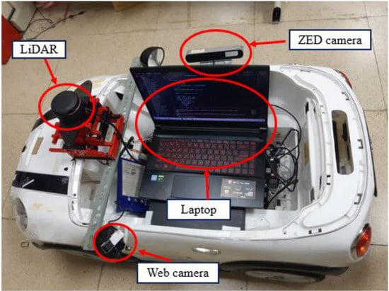
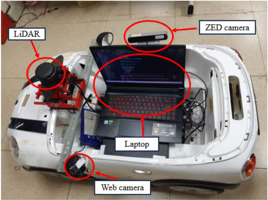
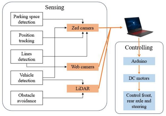
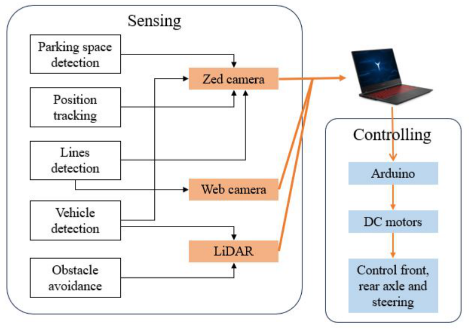
The complete automatic parking system comprises four hardware components: a ZED depth camera, a LiDAR sensor, a web camera, and two Arduino control boards, as illustrated in Figure 1. The system architecture is organized into three functional stages—sensing, judgment, and decision-making—where judgment is treated as a subcomponent of the sensing stage. As shown in Figure 2, the sensing and judgment stages involve computer processing of sensor data, encompassing parking space identification, space occupancy confirmation, vehicle orientation detection, and environmental obstacle recognition. The processed information is subsequently transmitted to the decision-making component, which governs higher-level control processes including parking initiation, mode selection, trajectory planning, and real-time adjustments during both driving and parking maneuvers.
Figure 1.
Architecture of vehicle.
Figure 2.
System mechanism.
The system is designed to fulfill the following control objectives:
- The vehicle autonomously identifies vacant parking spaces, determines their configuration, and executes smooth parking maneuvers.
- The vehicle employs its geometric turning radius for parking path planning.
- Through fuzzy control calibration, the vehicle achieves an optimal final parking pose.
3. Image Processing
Parking space detection involves three sequential stages: image acquisition, image preprocessing, and line detection. The following subsections describe each stage in detail.
3.1. Image Preprocessing for Parking Space and Vehicle Orientation Detection
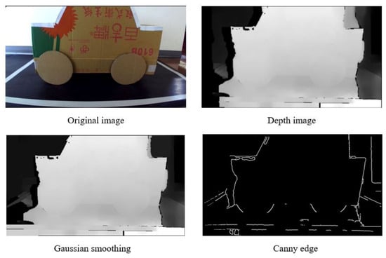
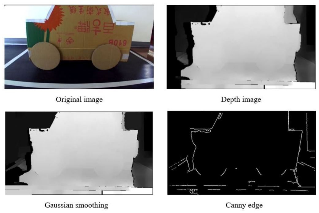
Prior to parking space detection, the system performs image preprocessing and noise reduction to minimize interference and improve processing reliability. The pipeline consists of three steps: acquiring depth images from the ZED depth camera, converting them to grayscale to reduce computational load, and applying a Gaussian blur to suppress high-frequency noise [15,16]. Following noise reduction, Canny edge detection is applied to highlight structural boundaries within the image. Canny edge detection is particularly effective under varying illumination conditions, enabling reliable identification of parking space boundaries regardless of ambient lighting, as illustrated in Figure 3.
Figure 3.
Image preprocessing pipeline for parking space detection.
3.2. Straight Line Detection via the Hough Transform
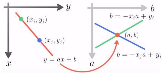
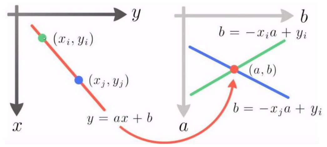
Once the edge map is obtained, the system locates parking space boundaries by identifying the coordinates of straight lines in the processed image. The Hough transform is applied to extract line features by mapping image-space points into a parameter space, where collinear points produce a prominent intersection peak [17,18]. The concept is illustrated in Figure 4. A straight line in the image plane is expressed as:
Figure 4.
The concept of the Hough transform.
Points in the image coordinate system are mapped to corresponding lines in the parameter space. Collinear points yield lines that intersect at a common point, which corresponds to the parameters of the detected line. The image coordinate system is set in , and the detected line is shown as the orange line in Figure 4.
For each line detected by the Hough transform, the endpoints are denoted as and . The slope of the line segment is then computed as , which is used in the subsequent parking space analysis.
4. Image Analysis and Judgment
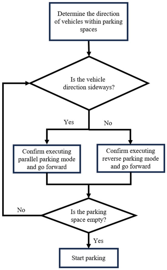
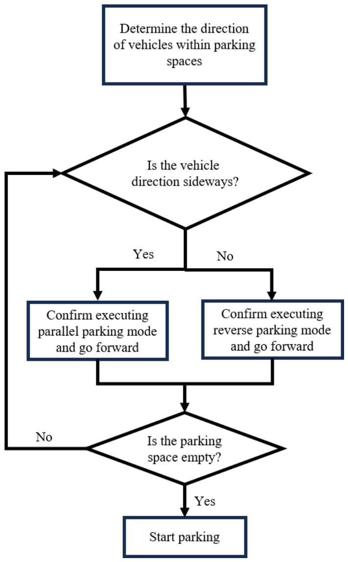
Based on the preprocessed image data, the system classifies the parking scenario into one of two modes: perpendicular parking or parallel parking. When a vehicle is detected within a parking space, the classification is determined by the vehicle’s apparent orientation in the image: a vehicle appearing directly ahead triggers perpendicular parking mode, whereas a vehicle detected from the side activates parallel parking mode. The two cases are illustrated in Figure 5 and Figure 6.
Figure 5.
Perpendicular parking space with an occupying vehicle.
Figure 6.
Parallel parking space with an occupying vehicle.
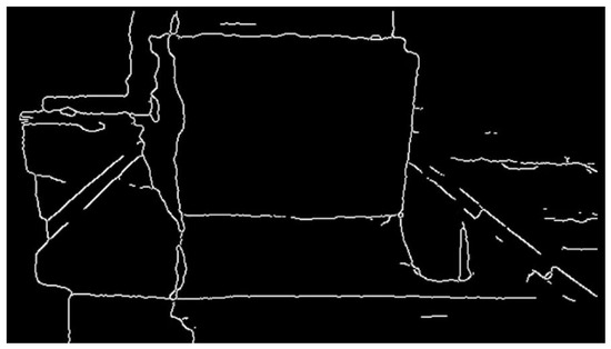
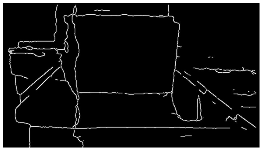
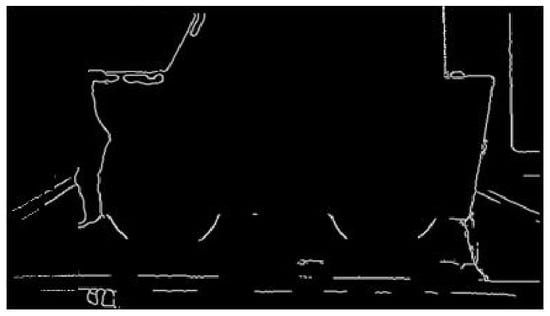
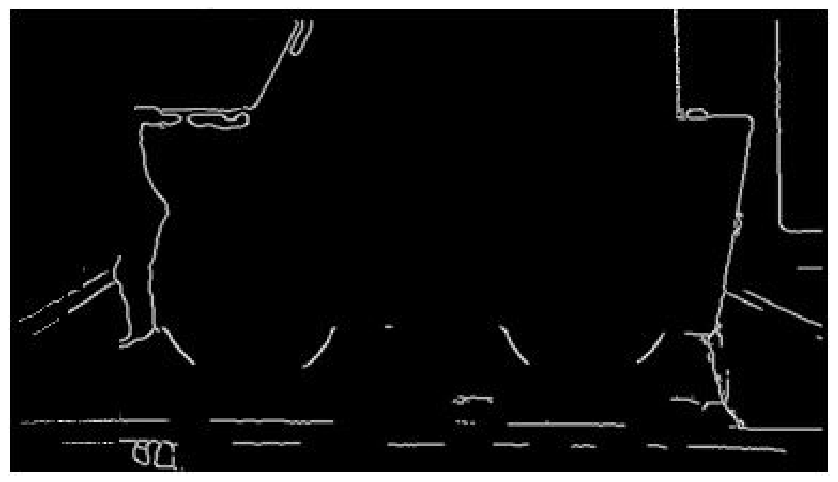
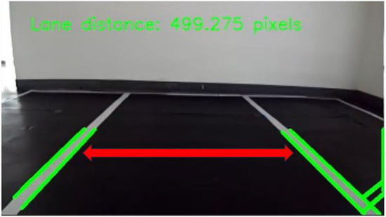
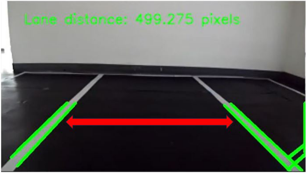
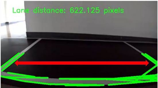
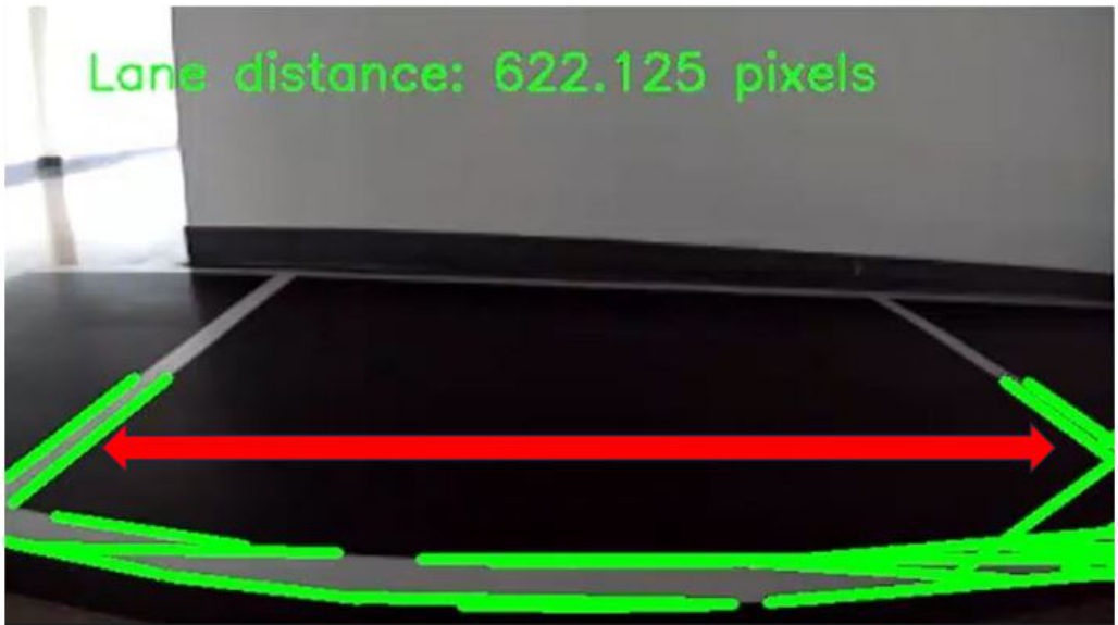
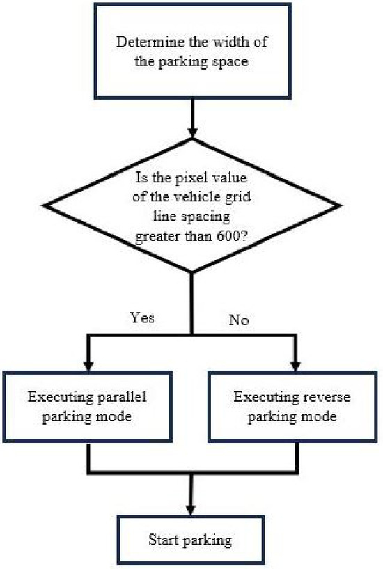
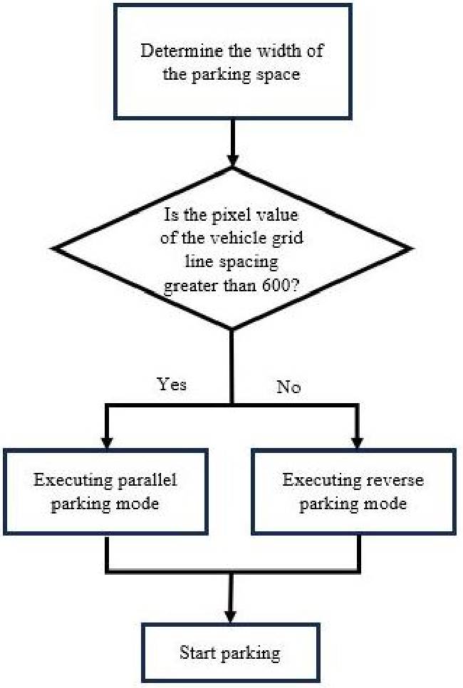
When no vehicle is detected within the target parking space, the system determines the parking mode based on the measured width of the available space. The Hough transform is applied to extract the left and right boundary lines, and the pixel distance between these lines is calculated. To establish a reliable classification criterion, multiple parking spaces of both types were analyzed under the same camera placement and imaging conditions. Experimental measurements showed that perpendicular parking spaces consistently produced widths ranging from approximately 300 to 550 pixels, whereas parallel parking spaces yielded widths between 600 and 1000 pixels, as illustrated in Figure 7 and Figure 8. Because a clear separation was observed between the two distributions, a classification threshold of 600 pixels was selected. Accordingly, spaces with measured widths below 600 pixels are classified as perpendicular parking spaces, while those with widths of 600 pixels or greater are classified as parallel parking spaces. This threshold was determined empirically from the experimental dataset and was applied unchanged across all test scenarios reported in Section 6. It should be emphasized that the 600-pixel value is not a viewpoint-invariant quantity: it depends on the mounting height, tilt, and field of view of the ZED camera and on the image resolution, and it would have to be re-derived for any other installation. A configuration-independent formulation, in which the metric width of the candidate space is recovered from the depth map and compared against a threshold expressed in physical units, would be preferable; this is not implemented in the present system and is identified as future work.
Figure 7.
Measured pixel width of a perpendicular parking space.
Figure 8.
Measured pixel width of a parallel parking space.
5. Intelligent Parking System Design
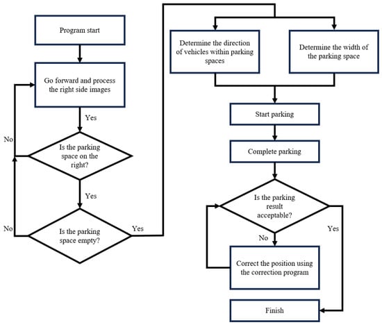
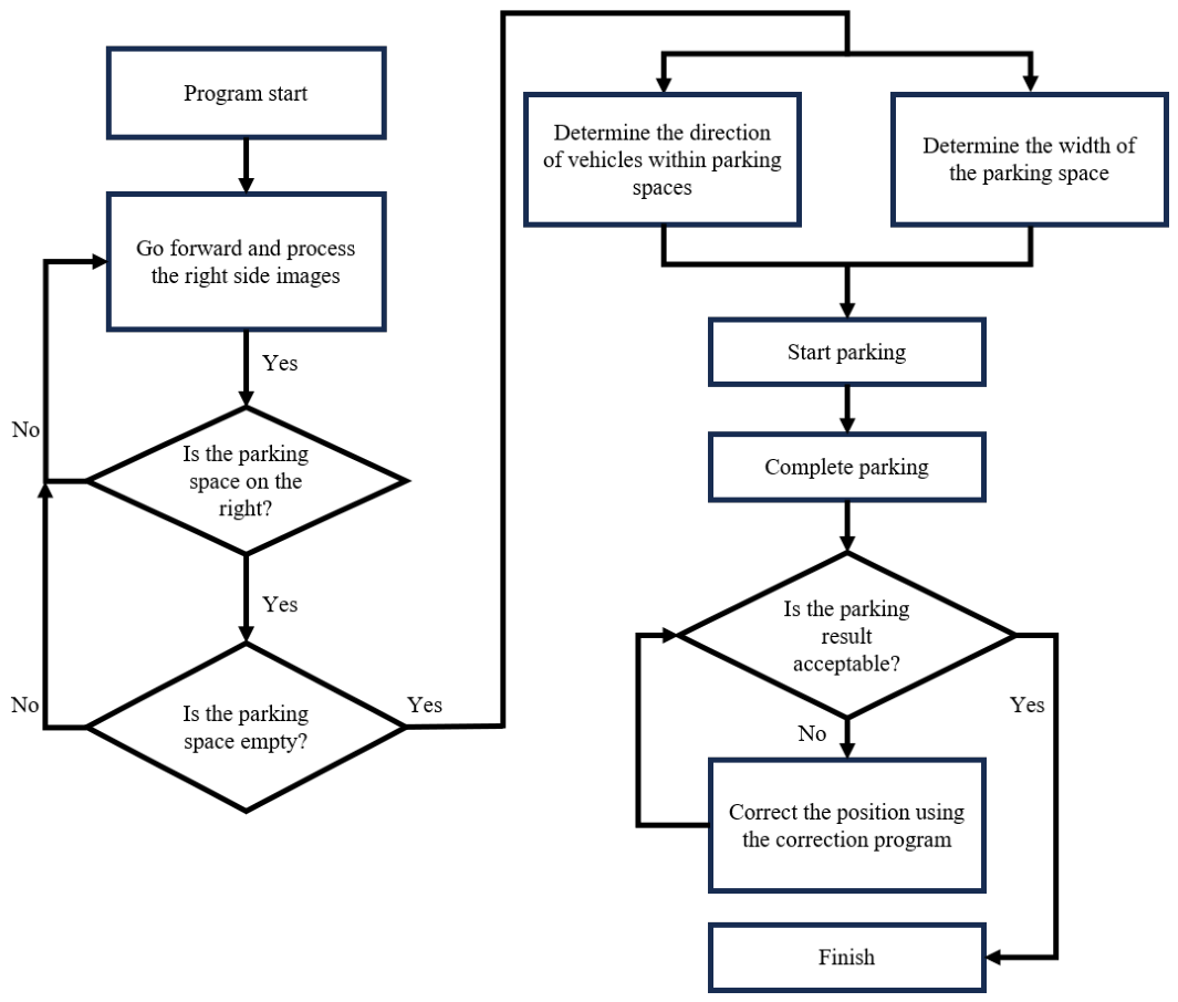
The intelligent parking system coordinates three sensors to collect comprehensive environmental information, which is transmitted to a central computer for processing. The computer subsequently issues commands to the Arduino control boards, which actuate the vehicle’s motors to execute the parking maneuver. Specifically, the ZED depth camera is responsible for detecting available parking spaces and surrounding vehicles; the web camera provides visual feedback for fuzzy-control-based pose correction; and the LiDAR continuously assesses space availability and detects obstacles or pedestrians along the planned trajectory [19]. The overall system workflow is illustrated in Figure 9, Figure 10 and Figure 11.
Figure 9.
Overall automatic parking system flow chart.
Figure 10.
Flow chart for parking space width determination.
Figure 11.
Flow chart for vehicle orientation determination.
5.1. Vacant Parking Space Detection with Obstacle Avoidance
LiDAR serves as the primary sensor for vacant space detection and obstacle avoidance, mounted on top of the vehicle to provide 360° environmental scanning. Its ability to accurately measure object distances and identify object shapes under varying lighting conditions makes it particularly suitable for nighttime operation. During the space search phase, LiDAR scans the surrounding area to determine whether obstacles or other vehicles are present within the candidate space, thereby preventing collisions [19]. During the parking maneuver itself, LiDAR operates analogously to a reverse radar, continuously monitoring the clearance between the vehicle and surrounding objects. If the measured distance falls below a predefined safety threshold, the system immediately issues a stop command to halt the vehicle.
5.2. Trajectory Planning Using Turning Radius
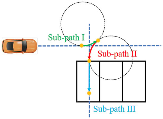
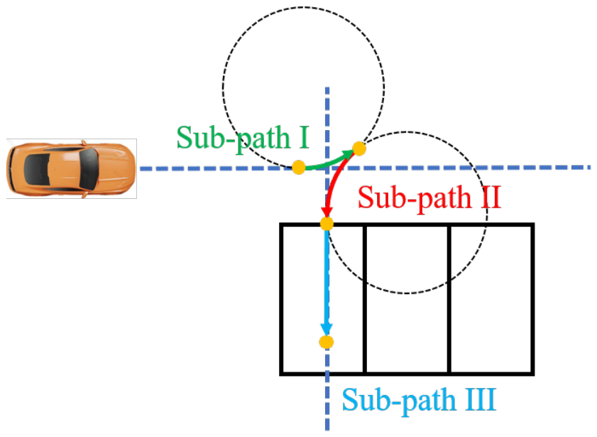
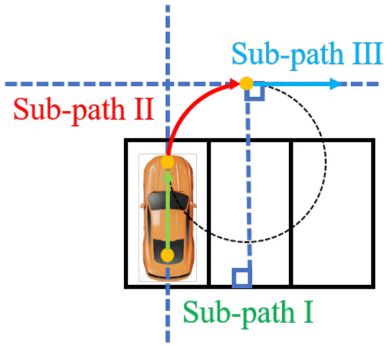
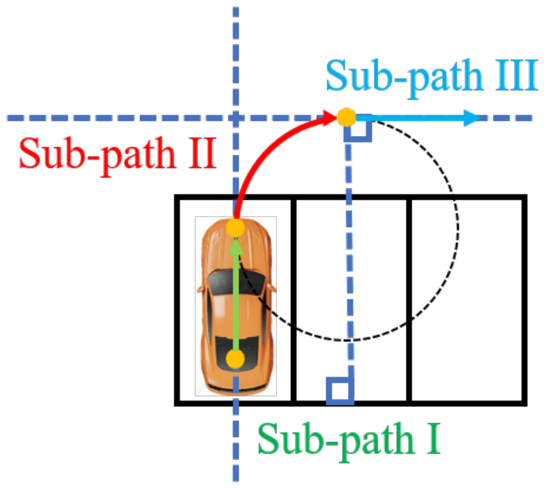
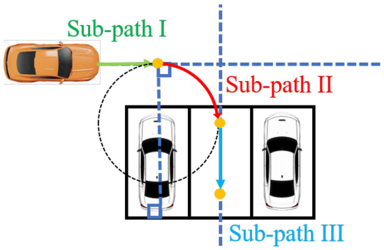
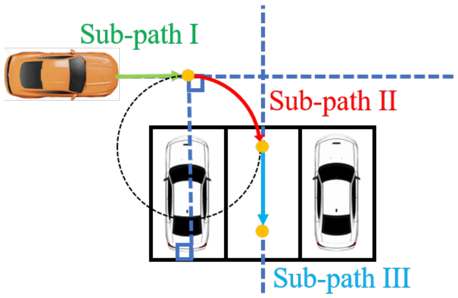
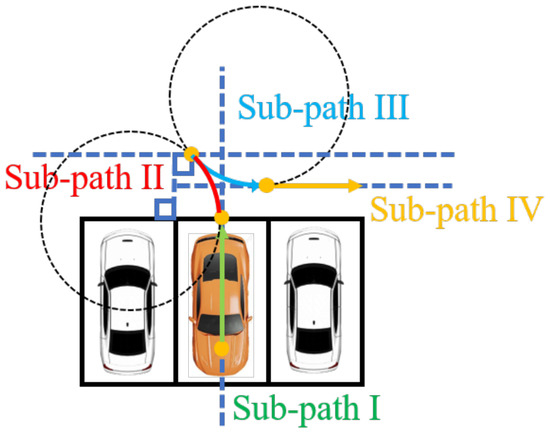
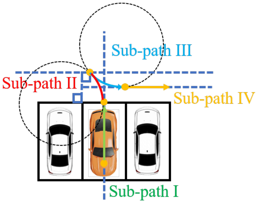
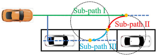
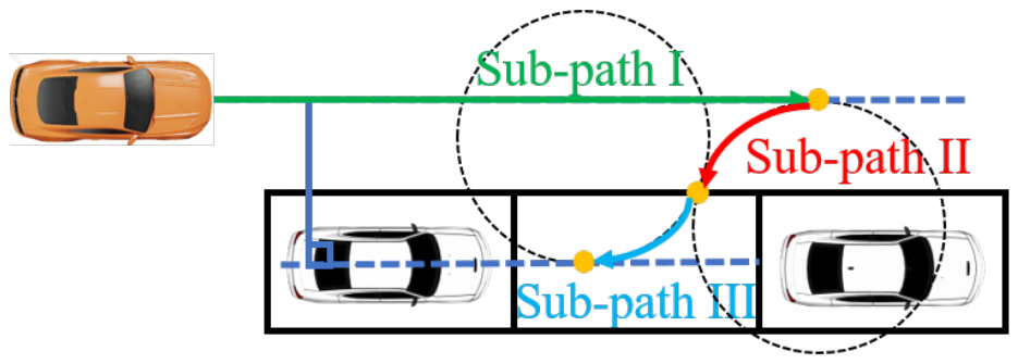
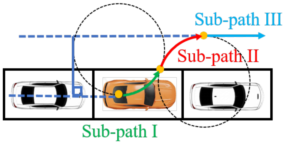
To guide the vehicle smoothly into the parking space, the system employs a trajectory planning strategy based on two turning radius circles, derived from an Ackermann steering geometry model [20,21]. The turning radius r is calculated as:
where
denotes the wheelbase length, and are the maximum right and left steering angles, respectively, and is their average. The trajectory planner determines the steering positions at which the vehicle must initiate each turn to ensure smooth entry into or exit from the parking space.
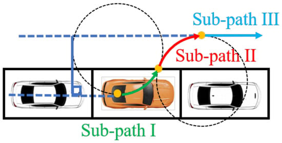
This construction is purely kinematic. The platform operates at low speed on a flat indoor surface, conditions under which the Ackermann model is a reasonable approximation and dynamic effects such as tire slip, lateral load transfer, and actuator lag are small. The model would not be adequate at higher speeds, on inclined or low-friction surfaces, or under external disturbance, where a dynamic vehicle model incorporating tire forces would be required. No such model is developed here. Figure 12, Figure 13, Figure 14, Figure 15, Figure 16, Figure 17 and Figure 18 illustrate the trajectories generated for each of the seven supported parking modes.
Figure 12.
Perpendicular parking mode 1: entering a vacant space backwards.
Figure 13.
Perpendicular parking mode 2: exiting an occupied space forwards.
Figure 14.
Perpendicular parking mode 3: entering a vacant space forwards.
Figure 15.
Perpendicular parking mode 4: exiting an occupied space backwards.
Figure 16.
Parallel parking mode 1: entering a vacant space backwards.
Figure 17.
Parallel parking mode 2: exiting an occupied space forwards.
Figure 18.
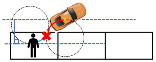
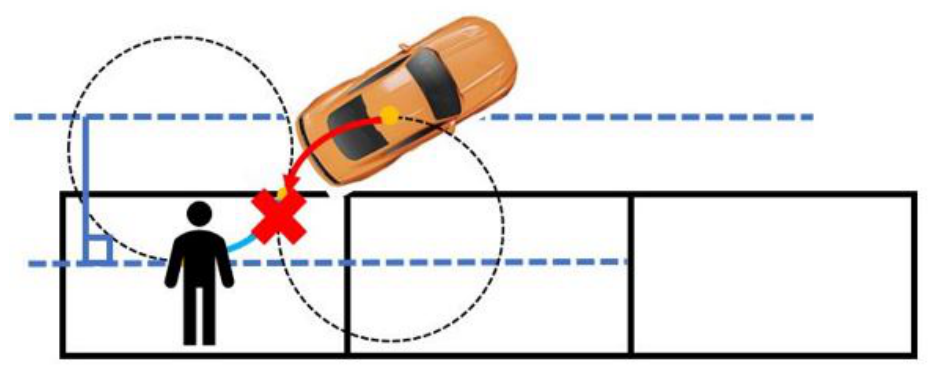
Parallel parking with dynamic obstacle avoidance.
5.3. Fuzzy Control-Based Fine-Tuning Mechanism
After the trajectory-based parking maneuver is completed, the vehicle may still deviate from its intended pose or slightly cross the parking boundary lines due to accumulated steering errors or sensor noise. To refine the final position and heading, a fuzzy-control-based fine-tuning mechanism is incorporated, using the web camera as the sensing modality. This approach avoids the need for additional complex models, thereby preserving the simplicity of the overall system architecture.
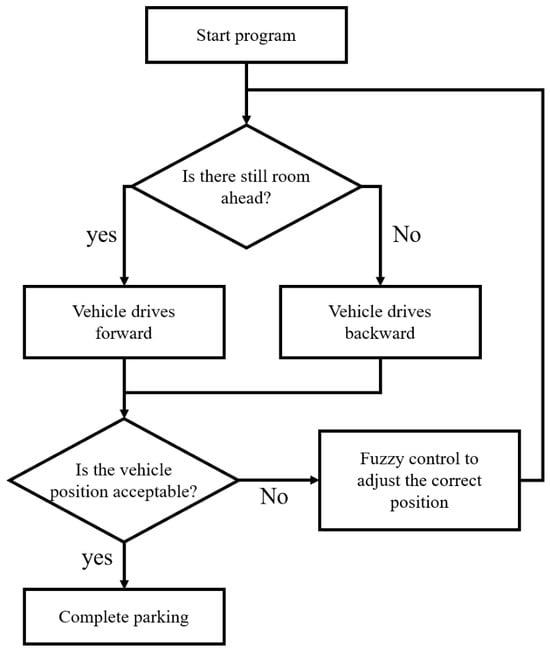
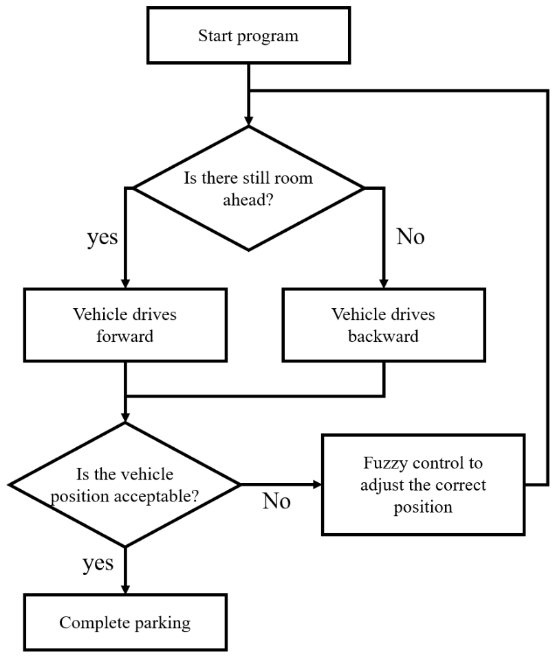
The web camera, mounted on the left side mirror, captures images of the parking space boundary lines. The system processes these images to estimate the vehicle’s lateral offset and angular deviation relative to the parking lines. Unlike model-based control strategies, the fuzzy controller operates directly on linguistic variables derived from image measurements, without requiring an explicit mathematical vehicle model. The correction process is illustrated in Figure 19, and proceeds through the following steps:
Figure 19.
Flow chart of the fuzzy control fine-tuning system.
- Image processing and position estimationThe camera captures the parking space boundary lines, and the system applies image processing to extract line features and compute the vehicle’s lateral position. The y-axis is set to a fixed constant K, and all intersections of the detected lines with are identified. The corresponding x-value, which is denoted as S, serves as the input to membership function . In addition, the slope of the detected parking line is denoted as G, which serves as the input to membership function .
- Membership function design
- (a)
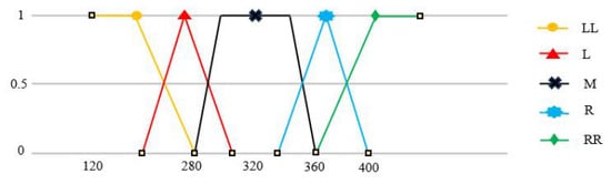
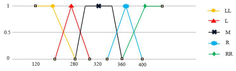
- Membership function (lateral position): This function categorizes the vehicle’s lateral offset relative to the parking lines into five linguistic states: Significantly Left (LL), Slightly Left (L), Centered (M), Slightly Right (R), and Significantly Right (RR), as shown in Figure 20.Figure 20. Input membership function .
- (b)
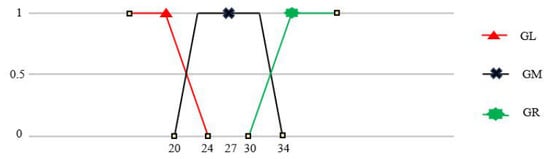
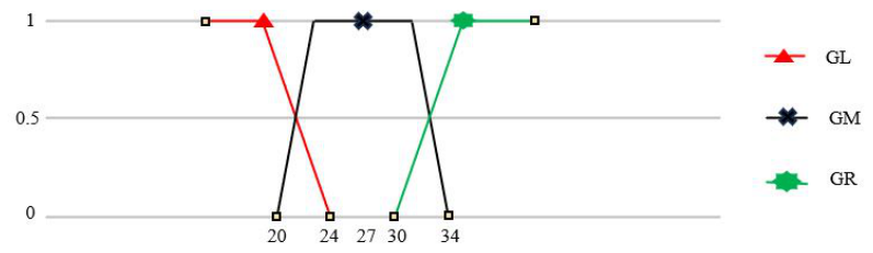
- Membership function (heading angle): Based on the slope of the parking lines, this function assesses the vehicle’s angular deviation and maps it to three states: Heading Right (GR), Heading Center (GM), and Heading Left (GL), as shown in Figure 21.Figure 21. Input membership function .
- (c)
- Breakpoint values: The breakpoints of the two membership functions are located at , 280, 320, 360, and 400 pixels for , and at , 24, 27, 30, and 34 for , as plotted in Figure 20 and Figure 21. These values were selected from the range of S and G observed across the two experimental layouts, so that the Centered (M) and Heading Center (GM) states span the tolerance within which the final pose was judged acceptable. They were set by hand and were not obtained by any systematic optimization procedure.
- Fuzzy rule tableThe fuzzy controller maps the combined inputs from and to one of seven correction actions: Aggressive Right (AR), Right (R), Slight Right (SR), Deadband (DB), Slight Left (SL), Left (L), and Aggressive Left (AL). The meaning of each action is defined in Table 1, and the complete rule table mapping every combination of and to one of these seven actions is given in Table 2. Each rule determines the steering correction based on the current lateral offset and heading deviation. For example, when both the lateral position and heading indicate a leftward deviation, the system commands a rightward correction to simultaneously realign the vehicle’s position and heading.Table 1. Explanation for the position correction output.Table 2. Fuzzy rule table of the correction system.
- Correction procedureUsing the camera data and the fuzzy rule table, the system iteratively corrects the vehicle’s pose. For example, if the initial image indicates a leftward heading (GL) and a leftward position (L), the vehicle adjusts rightward. As the position gradually centers, the system follows the rule table with progressively finer adjustments until both and reach the Centered (M) and Heading Center (GM) states, respectively, as illustrated in Table 2.
The fuzzy control rules were refined by hand across repeated experimental trials, on the basis of observed system behavior, until the corrected pose was judged acceptable in each supported mode. The correction mechanism thus reduces the residual lateral and angular error remaining after the turning-radius maneuver. The magnitude of that residual error was not measured.
6. Experiments and Results
The experimental environment consists of two parking layouts. The first layout contains three perpendicular parking spaces positioned against a wall, each measuring 130 cm in length and 80 cm in width. The second layout contains three parallel parking spaces along a wall, each measuring 86 cm in length and 140 cm in width. These dimensions are proportionally scaled from standard full-size parking space specifications. Seven test cases were conducted to evaluate the system across all supported parking modes:
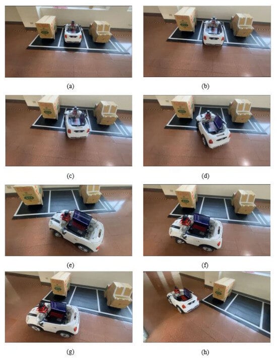
- Case (I): Perpendicular parking mode 1 (Figure 22). This case emulates an empty parking lot in which all perpendicular spaces are unoccupied. The absence of neighboring vehicles provides ample clearance and time for trajectory correction, enabling the vehicle to achieve an optimal final parking pose.
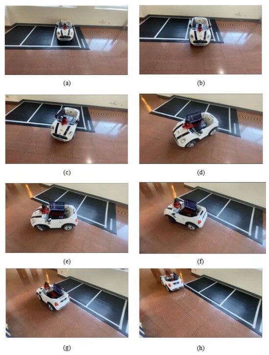
- Case (II): Perpendicular parking mode 2 (Figure 23). This case begins from the final parked state of Case (I) and evaluates forward exit from the perpendicular space. Because the vehicle reversed into the space in Case (I), it simply advances to align with the boundary line and turns right to exit.
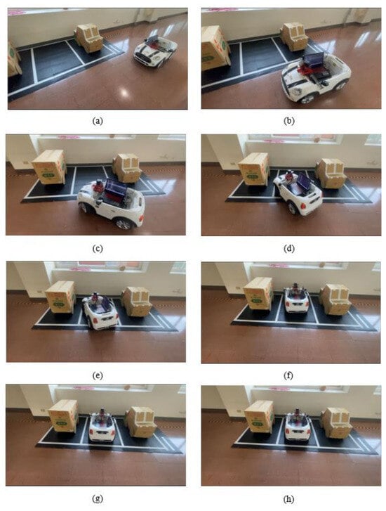
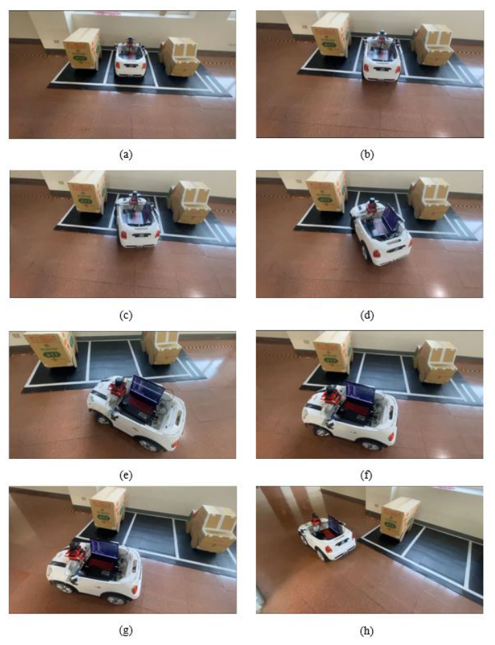
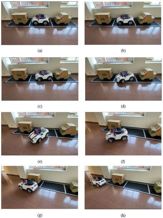
- Case (III): Perpendicular parking mode 3 (Figure 24). This case simulates a congested lot where vehicles are queued behind the ego vehicle and the spaces adjacent to the target space are occupied. Under these time constraints, a rapid forward-entry strategy with limited corrective maneuvers is employed.
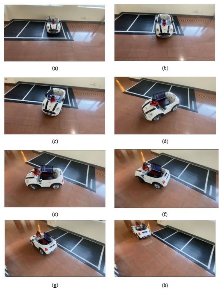
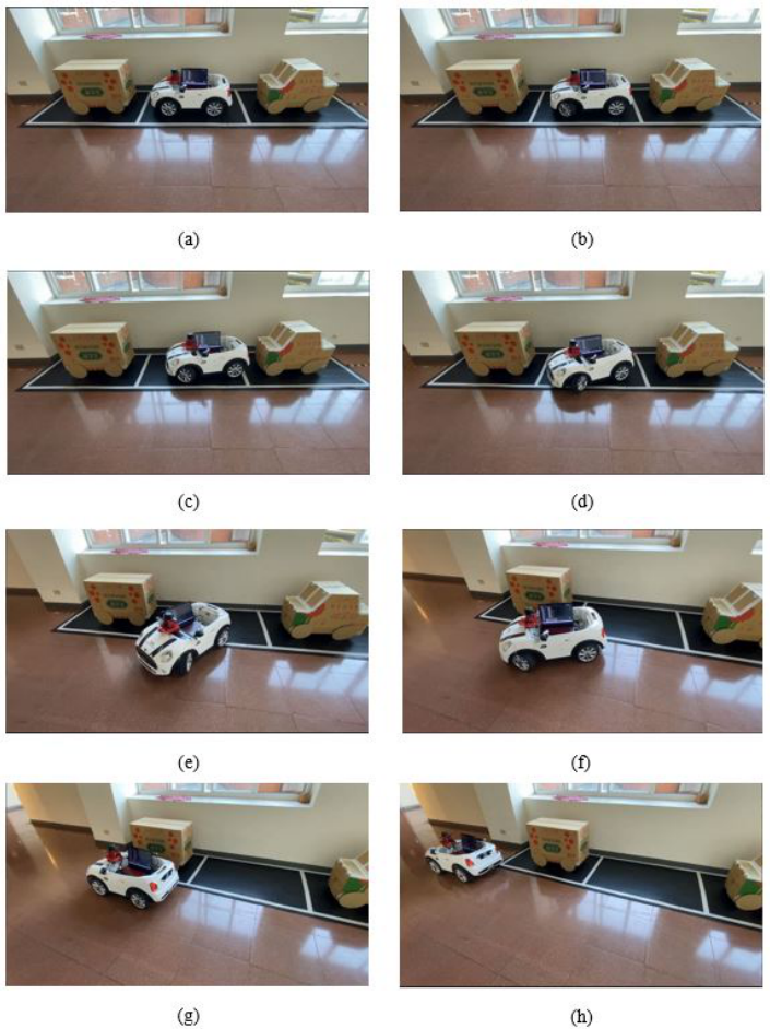
- Case (IV): Perpendicular parking mode 4 (Figure 25). This case continues from Case (III) and evaluates the exit maneuver. Because the vehicle entered head-first, it first reverses diagonally to the right toward the space boundary and then advances diagonally to the left to align with the traffic direction.
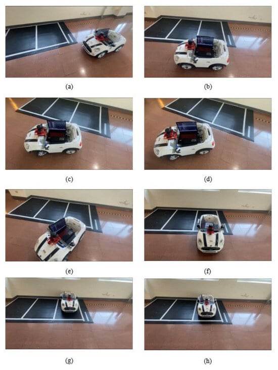
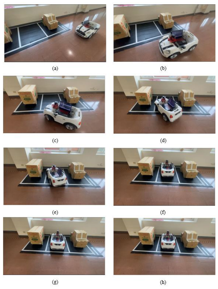
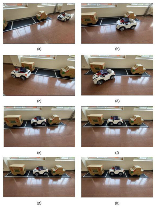
- Case (V): Parallel parking mode 1 (Figure 26). This case models roadside parallel parking using a single reverse maneuver in which the vehicle backs directly into the center of the space, thereby minimizing the need for fine adjustments after stopping.
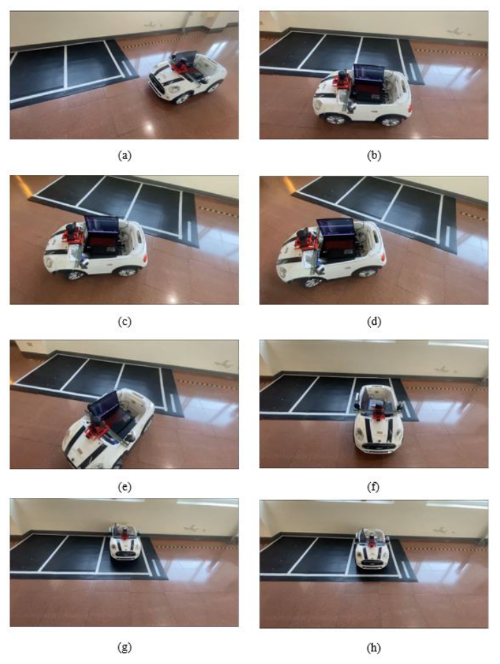
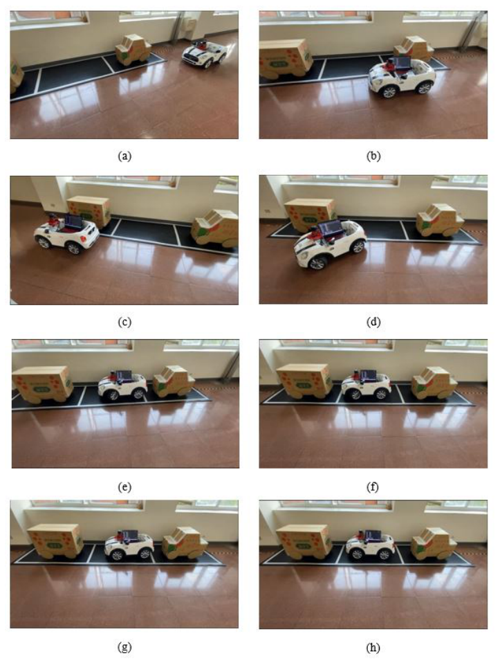
- Case (VI): Parallel parking mode 2 (Figure 27). This case begins from the final state of Case (V) and evaluates the parallel-space exit maneuver. The vehicle first reverses diagonally to the right so that its front faces outward, and then exits with a minimal turning radius along the shortest available path.
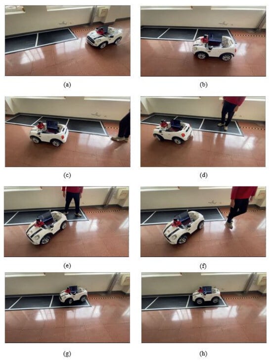
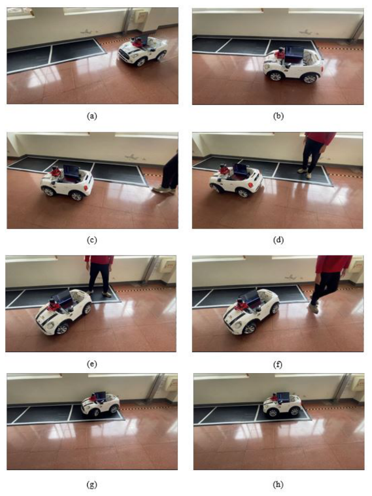
- Case (VII): Parallel parking with obstacle avoidance (Figure 28). This dynamic scenario evaluates the safety response of the system. After the ZED camera detects an empty space and initiates parallel parking, a pedestrian or obstacle is introduced onto the planned path. Upon LiDAR detection of the hazard, the vehicle immediately enters emergency stop mode and resumes parking only after confirming that the route is clear.
Figure 22.
Case (I): Perpendicular parking mode 1.
Figure 23.
Case (II): Perpendicular parking mode 2.
Figure 24.
Case (III): Perpendicular parking mode 3.
Figure 25.
Case (IV): Perpendicular parking mode 4.
Figure 26.
Case (V): Parallel parking mode 1.
Figure 27.
Case (VI): Parallel parking mode 2.
Figure 28.
Case (VII): Parallel parking with obstacle avoidance.
The experimental results presented in Figure 22, Figure 23, Figure 24, Figure 25, Figure 26, Figure 27 and Figure 28 show that the platform identified both perpendicular and parallel parking spaces and selected the appropriate parking mode from the real-time sensor data in all seven test conditions. The parking mode was classified correctly in seven of seven cases; the measured lane widths for the two representative detections are 499.3 pixels and 622.1 pixels (Figure 7 and Figure 8), which fall on either side of the 600-pixel criterion. In each of the seven cases, the vehicle completed the maneuver and came to rest within the designated space, as judged by visual inspection of the recorded images. In Case (VII), the vehicle stopped upon LiDAR detection of the obstacle on the planned path and resumed only after the path was confirmed clear.
Two limitations of this evaluation should be noted. The platform was not instrumented to log the final pose, the number of correction iterations, or the maneuver duration, so no pose-error, success-rate, or timing statistics are available, and each case corresponds to a single reported trial rather than to repeated trials under identical conditions. No comparison against a manual-parking baseline or an external system was performed; the platform is a scaled laboratory vehicle, and no comparable scaled benchmark was available. Quantitative characterization of positioning accuracy, repeatability, and timing is therefore required before any claim of precision or robustness can be supported.
7. Conclusions
This paper documents the design, implementation, and experimental evaluation of a modular intelligent parking system developed as a university research prototype. The system is not proposed as a replacement for or direct competitor to commercially deployed autonomous parking solutions; rather, it is presented as a transparent and reproducible platform intended to support ongoing academic inquiry into multi-sensor autonomous parking architectures.
The platform integrates ZED stereo depth imaging, LiDAR sensing, and web camera feedback to support both perpendicular and parallel parking across seven experimental scenarios. The processing pipeline—comprising grayscale conversion, Gaussian filtering, Canny edge detection, and Hough-transform line identification—performed space detection and mode classification correctly in all seven test cases. Ackermann-geometry-based trajectory planning guides the vehicle into position, and fuzzy control reduces the residual misalignment remaining at the end of the maneuver. As noted in Section 6, the accuracy of the final pose was not measured, and no claim of precision or robustness is made on the basis of the present results.
The principal contributions of this work to the academic community are threefold: (i) a fully documented multi-sensor architecture that integrates perception, planning, and control within a compact embedded platform, with the design parameters and their provenance stated explicitly; (ii) a set of clearly defined experimental protocols covering seven parking modes, which researchers may adopt or extend; and (iii) a demonstration that classical image-processing and rule-based control methods remain practically workable within the scope of laboratory autonomous parking, complementing the growing body of work on learning-based approaches.
Future work will focus first on quantitative characterization: instrumenting the platform to log final pose error, correction-iteration count, and maneuver duration, and repeating each scenario often enough to report success rates and variances. Further priorities are a configuration-independent replacement for the pixel-width classification criterion, a probabilistic treatment of the depth-camera and LiDAR measurements with explicit uncertainty propagation, and systematic or data-driven tuning of the fuzzy membership functions in place of manual refinement. Beyond these, work will address transitioning the platform toward unstructured real-world environments, incorporating semantic segmentation for boundary detection beyond marked lines, and evaluating robustness under adverse conditions including low illumination, rain, and occluded lane markings. Integration with vehicle-to-infrastructure (V2X) communication is also identified as a promising direction for cooperative parking in smart-city contexts.
Author Contributions
Conceptualization, J.-S.L.; methodology, J.-S.L. and Y.-L.W.; software, Y.-L.W.; validation, J.-S.L. and Y.-L.W.; formal analysis, Y.-L.W.; investigation, Y.-L.W.; resources, J.-S.L.; data curation, Y.-L.W.; writing—original draft preparation, Y.-L.W.; writing—review and editing, J.-S.L.; visualization, Y.-L.W.; supervision, J.-S.L.; project administration, J.-S.L.; funding acquisition, J.-S.L. All authors have read and agreed to the published version of the manuscript.
Funding
This research received no external funding.
Data Availability Statement
The original contributions presented in this study are included in the article. Further inquiries can be directed to the corresponding author.
Conflicts of Interest
The authors declare no conflicts of interest.
References
- Tan, Y.; Wang, J.; Liu, J.; Zhang, Y. Unmanned Systems Security: Models, Challenges, and Future Directions. IEEE Netw. 2020, 34, 291–297. [Google Scholar] [CrossRef] [Scilit]
- Wang, J.; Huang, H.; Zhi, P. Review of Development and Key Technologies in Automatic Driving. Appl. Electron. Tech. 2019, 45, 28–36. [Google Scholar]
- SAE Standard J3016_202104; Taxonomy and Definitions for Terms Related to Driving Automation Systems for On-Road Motor Vehicles. SAE International: Warrendale, PA, USA, 2021. Available online: https://www.sae.org/standards/j3016_202104-taxonomy-definitions-terms-related-driving-automation-systems-road-motor-vehicles (accessed on 23 August 2026).
- Medina, J.S.O.; Lázaro, J.G.M.; Rassõlkin, A.; Acuña, H.G. An Overview of Autonomous Parking Systems: Strategies, Challenges, and Future Directions. Sensors 2025, 25, 4328. [Google Scholar] [CrossRef] [Scilit]
- Zhang, C.; Zhou, R.; Lei, L.; Yang, X. Research on Automatic Parking System Strategy. World Electr. Veh. J. 2021, 12, 200. [Google Scholar] [CrossRef] [Scilit]
- Jo, Y.; Ha, J.; Hwang, S. Survey of Technology in Autonomous Valet Parking System. Int. J. Automot. Technol. 2023, 24, 1577–1587. [Google Scholar] [CrossRef] [Scilit]
- Lin, J.-S.; Wu, H.-J.; Hung, J.-W. Automatic Parallel Parking System Design with Fuzzy Control and LiDAR Detection. Electronics 2025, 14, 2520. [Google Scholar] [CrossRef] [Scilit]
- Liang, J.; Tan, C.; Yan, L.; Zhou, J.; Yin, G.; Yang, K. Interaction-Aware Trajectory Prediction for Safe Motion Planning in Autonomous Driving: A Transformer-Transfer Learning Approach. IEEE Trans. Intell. Transp. Syst. 2025, 26, 17080–17095. [Google Scholar] [CrossRef] [Scilit]
- Suhr, J.K.; Jung, H.G. Fully-Automatic Recognition of Various Parking Slot Markings in Around View Monitor (AVM) Image Sequences. In Proceedings of the 15th International IEEE Conference on Intelligent Transportation Systems, Anchorage, AK, USA, 16–19 September 2012. [Google Scholar]
- Bibi, N.; Majid, M.N.; Dawood, H.; Guo, P. Automatic Parking Space Detection System. In Proceedings of the 2nd International Conference on Multimedia and Image Processing, Wuhan, China, 17–19 March 2017. [Google Scholar]
- Verghese, S. Self-Driving Cars and LiDAR. In Proceedings of the Conference on Lasers and Electro Optics, San Jose, CA, USA, 14–19 May 2017. [Google Scholar]
- Cho, M. A Study on the Obstacle Recognition for Autonomous Driving RC Car Using LiDAR and Thermal Infrared Camera. In Proceedings of the Eleventh International Conference on Ubiquitous and Future Networks, Zagreb, Croatia, 2–5 July 2019. [Google Scholar]
- Hsu, C.-W.; Hsu, T.-H.; Chang, K.-J. Implementation of Car-Following System Using LiDAR Detection. In Proceedings of the 12th International Conference on ITS Telecommunications, Taipei, Taiwan, 5–8 November 2012. [Google Scholar]
- Singh, T.; Khan, S.S.; Chadokar, S. A Review on Automatic Parking Space Occupancy Detection. In Proceedings of the International Conference on Advanced Computation and Telecommunication, Bhopal, India, 28–29 December 2018. [Google Scholar]
- Rahul; Nair, B.B. Camera-based Object Detection, Identification and Distance Estimation. In Proceedings of the 2nd International Conference on Micro-Electronics and Telecommunication Engineering, Ghaziabad, India, 20–21 September 2018. [Google Scholar]
- Menon, A.S.; Ramachandran, K.I.; Adarsh, S. Distance Estimation & Driver alert system using ZED Stereo Camera and Raspberry Pi using Socket Communication. In Proceedings of the IEEE 20th India Council International Conference, Hyderabad, India, 14–17 December 2023. [Google Scholar]
- Stević, S.; Dragojević, M.; Krunić, M.; Četić, N. Vision-Based Extrapolation of Road Lane Lines in Controlled Conditions. In Proceedings of the Zooming Innovation in Consumer Technologies Conference (ZINC), Novi Sad, Serbia, 26–27 May 2020; pp. 174–177. [Google Scholar]
- Singh, V.J.; Rani, A.; Goyal, S. Improved Depth Local Binary Pattern for Edge Detection of Depth Image. In Proceedings of the IEEE 7th International Conference on Signal Processing and Integrated Networks, Noida, India, 27–28 February 2020. [Google Scholar]
- Peng, Y.; Qu, D.; Zhong, Y.; Xie, S.; Luo, J.; Gu, J. The Obstacle Detection and Obstacle Avoidance Algorithm Based on 2-D LiDAR. In Proceedings of the IEEE International Conference on Information and Automation, Lijiang, China, 8–10 August 2015; pp. 1648–1653. [Google Scholar]
- Baras, N.; Nantzios, G.; Ziouzios, D.; Dasygenis, M. Autonomous Obstacle Avoidance Vehicle Using LiDAR and an Embedded System. In Proceedings of the 8th International Conference on Modern Circuits and Systems Technologies (MOCAST), Thessaloniki, Greece, 13–15 May 2019; pp. 1–4. [Google Scholar]
- Zhang, Y.; Huang, J.C.; Zhang, J. Research on multi-directional automatic parking of Ackerman car model such as vertical parking, parallel parking and oblique parking. In Proceedings of the IEEE 2nd International Conference on Computer Science, Electronic Information Engineering and Intelligent Control Technology, Virtual, 23–25 September 2022. [Google Scholar]

Disclaimer/Publisher’s Note: The statements, opinions and data contained in all publications are solely those of the individual author(s) and contributor(s) and not of MDPI and/or the editor(s). MDPI and/or the editor(s) disclaim responsibility for any injury to people or property resulting from any ideas, methods, instructions or products referred to in the content. |
© 2026 by the authors. Licensee MDPI, Basel, Switzerland. This article is an open access article distributed under the terms and conditions of the Creative Commons Attribution (CC BY) license.