


Abstract
Deep mining operations in metal mines face escalating challenges from high in situ stress environments, where conventional single-method ground control approaches often prove insufficient. This study proposes an innovative combined protection technology integrating four synergistic components: (i) prestressed rock bolt and plate support for immediate roadway reinforcement, (ii) hydraulic fracturing-based shielding to create fracture zones isolating the orebody from surrounding high-stress regimes, (iii) destress blasting at the orebody crown to form a stress-transfer barrier, and (iv) subsequent cemented paste backfill to provide long-term regional stability. Theoretical formulations are derived for each component: a bolt–rock composite bearing model quantifies the confinement provided by prestressed support; a fracture mechanics-based model characterizes the stress-shielding efficiency of hydraulic fracture networks; controlled blasting theory predicts the stress redistribution achieved through crown destressing; and a backfill arching model evaluates the long-term load-bearing capacity of cemented paste fill. A three-dimensional FLAC3D numerical model was established to simulate six working conditions: no protection, support-only, shield-only, pressure relief-only, backfilling-only, and the integrated four-component system combining support, shield, pressure relief and backfilling. The numerical results reveal that the integrated composite protection system reduces roadway subsidence by 86%. Furthermore, the synergistic effect among all components exceeds the sum of individual contributions, which verifies the necessity of adopting the comprehensive protection strategy under deep high in situ stress conditions. The research findings provide theoretical basis and engineering design references for safe and efficient mining in deep metal mines.
1. Introduction
With the progressive depletion of shallow mineral resources, metal mining operations worldwide have extended to depths exceeding 1000–3000 m [1]. As mining depth increases, the in situ stress magnitude grows substantially, with major principal stresses frequently reaching 30–70 MPa or higher in tectonically active regions [2,3]. Under these extreme stress conditions, conventional ground control measures—designed for shallow to moderate depths—exhibit markedly diminished effectiveness, leading to a cascade of engineering challenges including severe roadway convergence, rockburst hazards, and uncontrollable roof falls [4,5].
The fundamental difficulty in deep high-stress mining lies in the multi-scale nature of the problem. At the excavation scale, stress redistribution around openings creates localized concentrations that may exceed the rock mass strength by a factor of 2–5 [6]. At the stope scale, mining-induced stress transfer can activate pre-existing geological structures, triggering seismic events that compromise the integrity of adjacent excavations [7]. At the mine scale, regional stress reorientation associated with progressive extraction can generate far-field effects that were unforeseen at the design stage.
These challenges demand a paradigm shift from reactive, single-method ground support toward proactive, multi-component protection strategies that address stress management at all relevant scales.
The literature on deep mining ground control has evolved through several distinct phases. Early work focused primarily on passive support systems—the installation of rock bolts, cable bolts, steel sets, and shotcrete to contain rock-mass deformation after it had already initiated [8,9]. While effective at moderate depths, these passive approaches proved inadequate when confronted with the energy release magnitudes characteristic of deep high-stress environments [10].
The recognition that active stress management could yield superior outcomes led to the development of destressing techniques. Destress blasting, pioneered in South African gold mines and subsequently refined in Canadian and Australian hard rock operations, demonstrated that controlled fracturing of the rock mass could redistribute stresses away from vulnerable excavations [11]. Parallel developments in coal mining established hydraulic fracturing as a viable stress control method, particularly for managing hard roof strata and mitigating coal burst hazards [12,13].
More recently, the concept of high-prestress active support has gained prominence. Building on the compensation theory proposed by He et al. [14], researchers have demonstrated that rock bolts installed with high initial tension can actively confine the surrounding rock mass, mobilizing its residual strength and creating a self-supporting arch [15,16]. The development of constant-resistance large-deformation (CRLD) bolts and negative Poisson’s ratio (NPR) bolts has further extended the applicability of prestressed support to squeezing ground conditions [17,18]. Kumar S et al. [19] adopted the random-forest method to predict back-break in mine blasting using variables including the ratio of charge mass to hole spacing, the ratio of stemming length to hole depth, P-wave velocity, and explosive density.
Cemented paste backfill (CPB) technology represents another significant advancement. Beyond its primary function of providing ground support for subsequent extraction sequences, CPB contributes to regional stress stabilization by filling mined-out voids and reducing the potential for large-scale stress redistribution [20]. The arching effect within backfilled stopes, extensively studied by Li and Aubertin [21] and Xie and Wang [22], provides an additional stress management mechanism that has been underexploited in deep mining design. C. Mark [23] discussed the characteristics of roof bolts, including anchorage mechanism, prestress, length, bearing capacity, installation timing and construction quality, based on recent research achievements, and proposed several simple principles for the preliminary design of roof-bolt systems.
Despite these advances, the limitations of single-method approaches become apparent when applied individually to deep high-stress environments. Support-only strategies, even with high-prestress systems, cannot fundamentally alter the in situ stress field and may be overwhelmed by stress magnitudes exceeding 50–70 MPa [24]. Destressing alone creates stress shadows but may introduce unintended damage to adjacent excavations if not precisely controlled [25]. Hydraulic fracturing effectively isolates stress but requires careful design to avoid water management complications and unfractured “blind spots” [26]. Backfill provides long-term stability but offers limited protection during the critical extraction phase before placement.
The integration of multiple techniques—systematically combining support, shielding, destressing, and backfill into a unified protection strategy—represents a logical but underexplored frontier in deep mining engineering. The synergistic potential lies in the complementary spatial and temporal domains of each technique: support acts immediately at the excavation boundary; shielding and destressing modify the far-field stress environment before mining commences; and backfill provides long-term regional stabilization after extraction.
Against this background, the present study proposes and systematically investigates a combined “Support–Shielding–Destressing–Backfill” (SSDB) protection technology for deep high-stress metal mining environments. The specific objectives are: (i) to derive the theoretical formulations governing each component of the SSDB system and quantify their individual contributions to stress management; (ii) to develop and validate a three-dimensional numerical model capable of simulating the coupled behavior of all four components; and (iii) to provide practical design recommendations for the implementation of combined protection strategies in deep metal mines.
2. Theoretical Framework of the Combined Protection System
The combined protection system integrates four protective mechanisms operating at different spatial scales and temporal stages of the mining sequence. This section derives the governing equations for each component and establishes the theoretical basis for their synergistic interaction.
2.1. Prestressed Rock Bolt and Plate Support
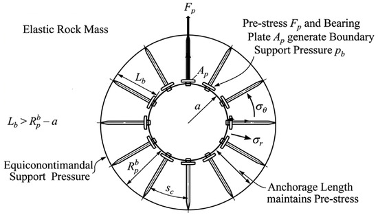
Figure 1 shows the schematic diagram of bolt and plate support.
Figure 1.
Schematic of prestressed rock bolt and plate support.
Consider a circular roadway of radius a excavated in a homogeneous, isotropic rock mass subjected to a hydrostatic in situ stress field . Upon excavation, a plastic zone of radius develops around the opening. The installation of prestressed rock bolts with end plates creates a confining pressure on the excavation boundary, modifying the stress distribution within the plastic zone. The bolt provides an active radial support pressure at the excavation wall, which can be expressed as
where n is the number of bolts per row, Fp is the prestress force per bolt, sl is the longitudinal bolt spacing, and Sc is the circumferential bolt spacing. The bearing plate distributes this force over an area Ap, producing an equivalent surface pressure:
where is a load distribution efficiency factor (0.7 ≤ ≤ 0.95) accounting for the non-uniform contact between the plate and the irregular excavation surface.
Following the elasto-plastic analysis framework established by Fenner [27] and extended by Kastner [28] for supported openings, the radial and tangential stresses in the plastic zone with bolt support are
where c is the cohesion, is the internal friction angle, and a ≤ r ≤ Rp. The enhanced confinement due to bolt prestress shifts the ground reaction curve upward, enabling equilibrium at a smaller radial displacement. The plastic zone radius with bolt support, Rp, satisfies
The bolt length Lb must exceed the plastic zone thickness (Lb > Rpb − a) to ensure anchorage in the elastic zone, providing the necessary reaction force for prestress maintenance.
The grouted bolt–rock interface sustains the prestress through shear stress transfer. Following Farmer [29] and Li and Stillborg [30], the shear stress distribution along a fully grouted bolt under tension can be expressed as
where α2 = 2GrGg/[Ebln(rg/rb)], Gr is the rock shear modulus, Gg is the grout shear modulus, Eb is the bolt elastic modulus, rb is the bolt radius, and rg is the borehole radius. The decay parameter α controls the load transfer length—a larger a indicates more rapid stress transfer to the surrounding rock. The critical anchorage length La, over which 95% of the prestress force is transferred, is
For effective support, the grouted length must satisfy Lg ≥ La, ensuring that the bolt can sustain its design prestress without debonding.
2.2. Hydraulic Fracturing-Based Stress Shielding
2.2.1. Theoretical Model of Hydraulic Fracturing
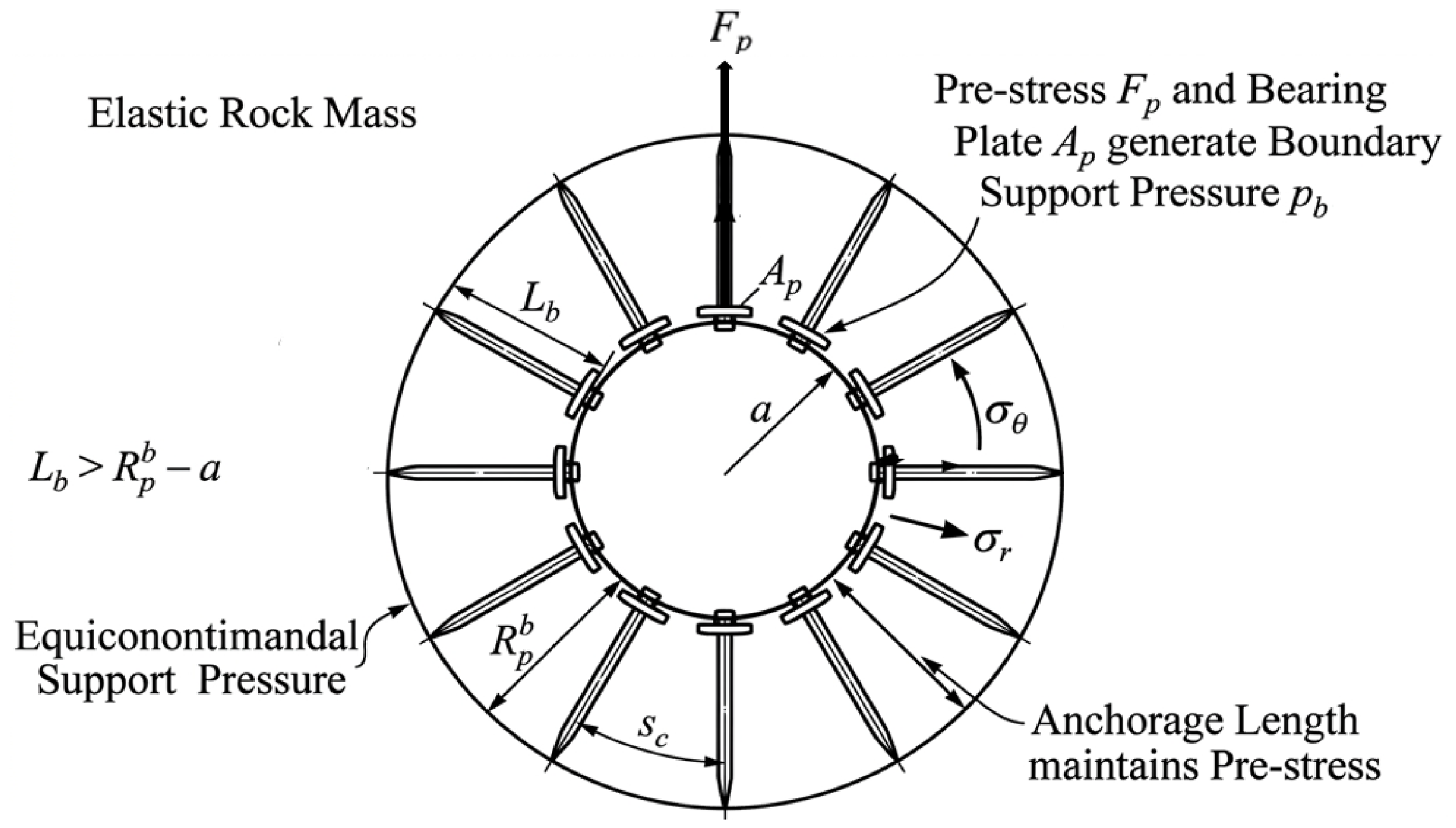
Figure 2 shows the schematic diagram of stress shielding protection based on hydraulic fracturing.
Figure 2.
Schematic diagram of stress shielding protection based on hydraulic fracturing.
The stress shielding component employs hydraulic fracturing to create controlled fracture networks along both sides of the orebody. These fracture zones serve as compliant inclusions that isolate the mining area from far-field stress transmission. For a vertical borehole in a medium subjected to principal stresses σH (maximum horizontal), σh (minimum horizontal), and σv (vertical), the breakdown pressure Pb required for fracture initiation is given by the Hubbert–Willis criterion:
where σt is the tensile strength of the rock and P0 is the pore pressure. Once initiated, the fracture propagates when the stress intensity factor at the crack tip reaches the fracture toughness KIC:
where Pf is the fluid pressure in the fracture, Lf is the fracture half-length, and is a geometry factor accounting for fracture aspect ratio and interaction effects.
The density and connectivity of the induced fracture network govern its stress-shielding effectiveness. The fracture density parameter is defined as
where is the number of fractures within a representative volume and is the mean fracture length.
According to the non-interacting crack model of Budiansky and O’Connell, the reduction in the effective elastic modulus for fractured rock mass relative to the intact-rock modulus is given by
Consider a simplified two-dimensional model where a fracture zone of width wf and reduced modulus Ef is positioned between the far-field stress source and the protected roadway. The stress transmission coefficient , defined as the ratio of the stress reaching the roadway to the far-field stress, is expressed as
where Df is the distance from the roadway to the inner edge of the fracture zone, and is the far-field stress magnitude. A stress-shielding efficiency can be defined as
2.2.2. Parametric Sensitivity of Hydraulic-Fracturing Stress Shielding
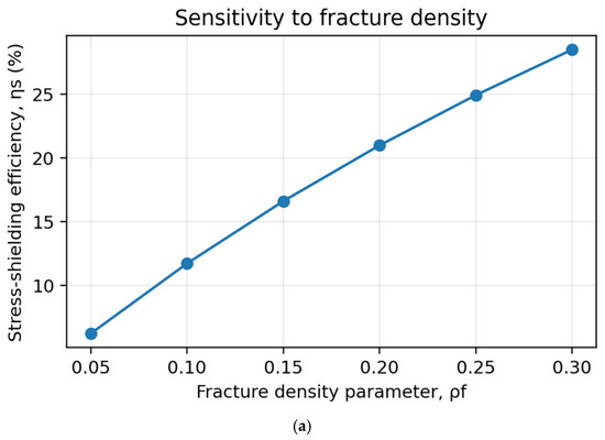
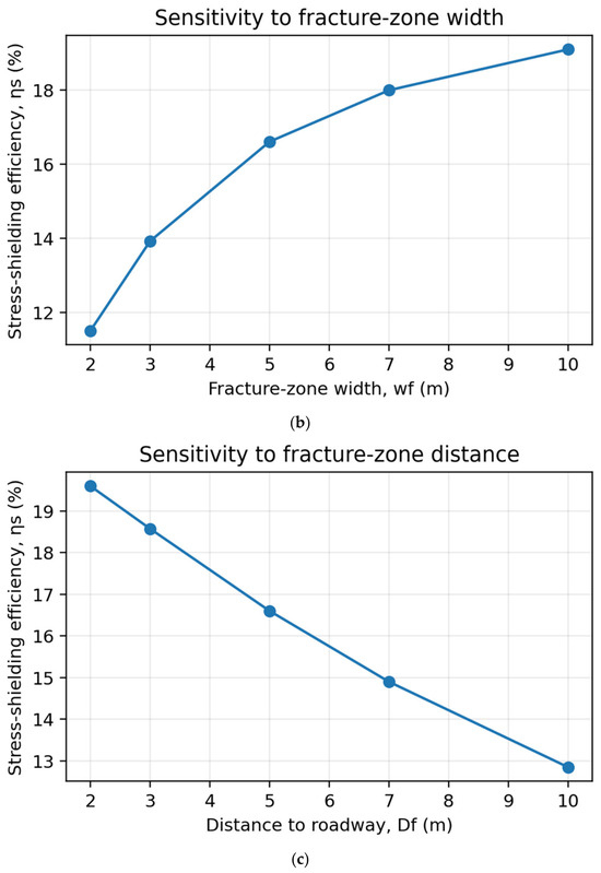
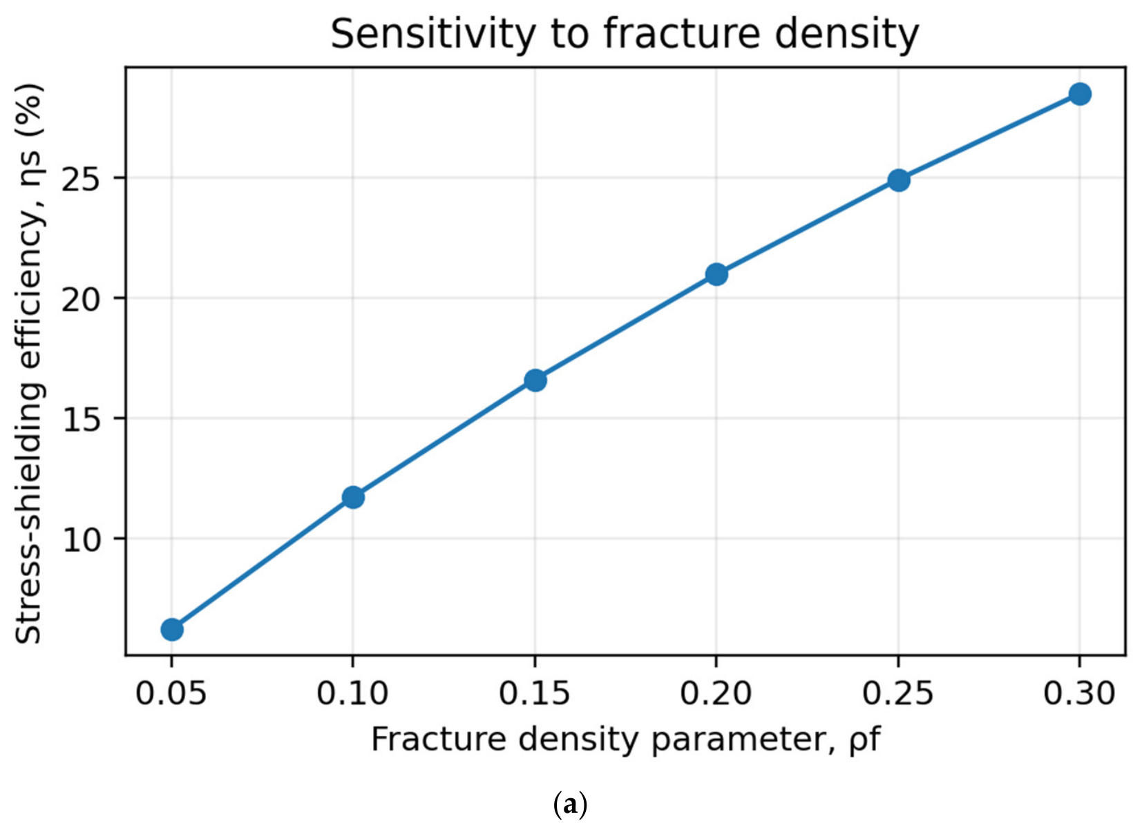
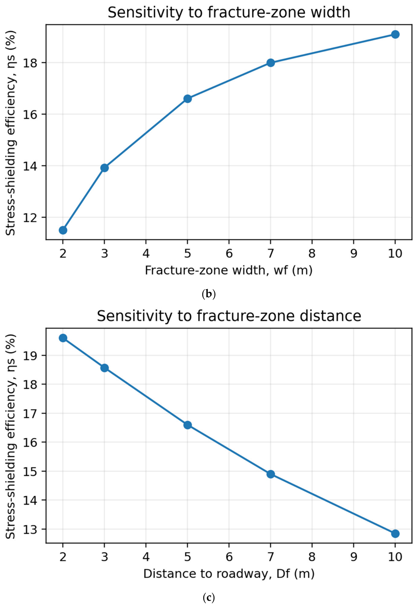
To address the dependence of shielding performance on the geometry and development degree of the induced fracture zone, a one-factor-at-a-time parametric analysis was performed using Equations (9)–(12). The numerical model in Section 3.1 adopts a fracture-zone width wf = 5 m and a distance Df = 5 m from the orebody; these values were therefore taken as the geometric reference case. Because no site-measured fracture-density calibration is available in the present study, the fracture-density effect in Equation (10) was normalized to the numerical shielding result rather than assigned an independently measured material constant. A reference value ρf = 0.15 was used, and the modulus-reduction coefficient was calibrated so that the theoretical model reproduces the 16.6% stress reduction obtained for the shielding group. The resulting reference modulus ratio Ef/E0 is 0.790. The examined ranges were ρf = 0.05–0.30, wf = 2–10 m, and Df = 2–10 m, with the other two parameters fixed at their reference values in each calculation.
Figure 3 shows the sensitivity of bolt parameters.
Figure 3.
(a) Sensitivity of stress shielding to fracture density. (b) Sensitivity of stress shielding to fracture-zone width. (c) Sensitivity of stress shielding to distance from the protected roadway.
The sensitivity curves demonstrate that fracture density has the strongest influence within the investigated range. When ρf increases from 0.05 to 0.30, the shielding efficiency ηs increases from 6.22% to 28.47%, corresponding to a gain of 22.25 percentage points. The increase becomes progressively smaller at high fracture density because the effective modulus reduction tends toward an asymptotic response. Increasing the fracture-zone width from 2 to 10 m increases ηs from 11.50% to 19.09%. The improvement is most pronounced between 2 and 5 m, whereas further widening produces diminishing returns. In contrast, increasing the stand-off distance Df weakens shielding: ηs decreases from 19.60% at Df = 2 m to 12.85% at Df = 10 m.
These results indicate that an effective hydraulic-fracturing design should first ensure a sufficiently dense and connected fracture network, after which increasing the fractured-zone width provides only moderate additional benefit. A smaller stand-off distance is favorable for stress interception, but it cannot be reduced without limit because excessive proximity may induce hydraulic damage, deformation, or water inflow into the excavation. Accordingly, the 5 m wide fractured zone located 5 m from the orebody in the present numerical model should be regarded as a balanced reference configuration rather than a universal optimum. For field application, ρf, wf, and Df should be updated using fracture mapping, microseismic response, water-pressure records, and numerical back-analysis, and the final layout should be accepted only after the target stress reduction is achieved without creating unacceptable damage to the protected roadway.
2.3. Theory of Crown Destress Blasting
Destress blasting at the orebody crown creates a fractured “cushion” zone that absorbs and redirects stresses that would otherwise concentrate in the roof of the extraction area. The blast-induced damage zone is characterized by a rock fragmentation factor :
where and are the bulk moduli of the damaged and intact rock, respectively. For a typical destress blast design with a burden B and spacing S,
where db is the blasthole diameter and is an empirical damage coefficient ( approx 0.3~0.7 for hard rock). The radius of the equivalent damaged zone around each blasthole, , can be estimated using the Holmberg–Persson approach:
where is the borehole radius, is the explosive density, VOD is the velocity of detonation, is the uniaxial compressive strength, and and are rock-specific attenuation parameters.
The destressed zone acts as a stress barrier, redirecting the vertical stress component around the extraction area. The effectiveness of stress transfer can be quantified through a stress reduction factor applied to the vertical stress above the destressed zone:
where is the original vertical stress at depth z, and
Here, is the effective height of the destressed zone (typically 3–8 m for production blasting patterns) and is the elevation of the destressed zone center. The transferred stress is redistributed to the abutments on either side of the extraction area, with the abutment stress concentration factor approximated by
where is the stope width, is the abutment width, and is the average stress reduction factor across the destressed zone.
2.4. Subsequent Cemented Paste Backfill
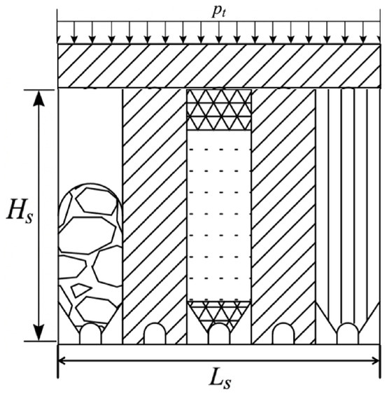
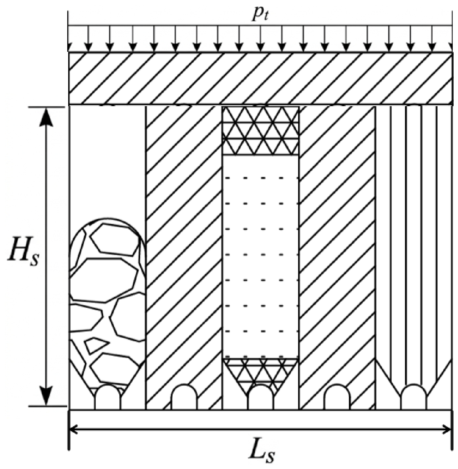
Figure 4 shows the schematic diagram of subsequent backfill.
Figure 4.
Schematic diagram of subsequent backfilling.
Following primary stope extraction, the mined void is backfilled with cemented paste backfill (CPB). The stress distribution within the backfilled stope is governed by the arching effect—the transfer of vertical load from the fill material to the stope walls through shear stress mobilization at the fill–rock interface. For a stope of width , length Ls, and height Hs, the vertical stress at elevation y (measured from the stope floor) is as follows [31]:
where is the backfill unit weight, is the lateral earth pressure coefficient of the backfill (K = νb/(1 − νb) or Rankine’s coefficient), is the interface friction angle between the backfill and the rock wall, and pt is the surcharge pressure at the top of the backfill column.
The horizontal stress in the backfill is
The arching effect reaches an asymptote at a critical height beyond which the vertical stress no longer increases with depth:
For typical CPB parameters (K = 0.4, = 25°, = 15 m), 80 m, meaning that for stope heights exceeding this value, the maximum vertical stress in the backfill is
which is substantially lower than the overburden pressure Hs. The CPB gains strength through cement hydration, with the uniaxial compressive strength evolving according to
where is the 28-day UCS, t is the curing time in days, and n is a hydration exponent (typically n = 0.3~0.5 for tailings-based CPB with 4–7% binder content).
The required backfill strength for free-standing stability during secondary stope extraction is given by the Mitchell solution [32]:
where Fs is a safety factor (typically 1.3–1.5).
Beyond its local support function, backfill contributes to regional stress stabilization by reducing the overall void ratio in the mining area. The post-backfill stress state can be approximated using an equivalent continuum approach where the backfill–rock composite has a modified deformation modulus:
where is the backfill volume ratio and is the time-dependent backfill modulus.
2.5. Unified Framework for the Coupled Protection Mechanisms
Although the four protection measures act at different spatial locations and mining stages, they ultimately influence the same mechanical process, namely the redistribution of stress and the evolution of deformation around the excavation and stope system. Therefore, instead of considering them as completely independent mechanisms, their effects can be conceptually integrated into a unified ground-response framework.
The deformation response of the protected rock mass can be generally expressed as
where U represents the deformation response of the surrounding rock, σeff is the effective stress state after stress redistribution, Keff represents the equivalent stiffness of the rock–support–backfill system, Ceff represents the confinement effect provided by active support and backfill, and Beff represents the weakening or stress-release effect introduced by hydraulic fracturing and destress blasting.
Within this framework, the four protection components modify different controlling variables:
where ηh and ηd denote the equivalent stress-reduction efficiencies associated with hydraulic-fracturing shielding and destress blasting, respectively. These two mechanisms primarily affect the stress-transfer path before and during mining.
The confinement contribution of support and backfill can be represented as
where Cb is the confinement provided by prestressed bolts and bearing plates, and Ccp is the confinement contribution from cemented paste backfill. These two components mainly enhance the post-excavation and post-extraction load-bearing capacity.
The equivalent stiffness of the protected system may be expressed conceptually as
where Kr is the stiffness of the intact rock mass, Kb and Kcpb represent the stiffness contributions of bolts and backfill, and ΔKh and ΔKd represent the stiffness reductions caused by hydraulic fracturing and destress blasting.
3. Research Methods and Effect Analysis
3.1. Numerical Model and Simulation Procedure
FLAC3D was used to establish a three-dimensional finite-difference model, and the Mohr–Coulomb constitutive model was used to describe the mechanical behavior of ore and rock. The roadway model dimensions were 21 m × 8 m × 18 m. In addition to self-weight stress, a vertical load of 16.69 MPa was applied on the top to simulate the deep in situ stress environment. The sides and bottom of the model were displacement-constrained, while the top surface was free to deform. The support group was configured with five radial bolts and a pretension of 100 kN, while the control group underwent excavation only. The mechanical parameters of rock mass are shown in Table 1.
Table 1.
Mechanical parameters of rock mass.
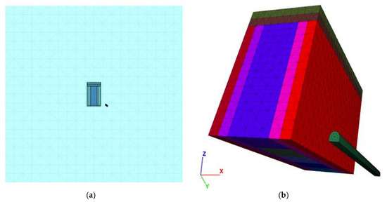
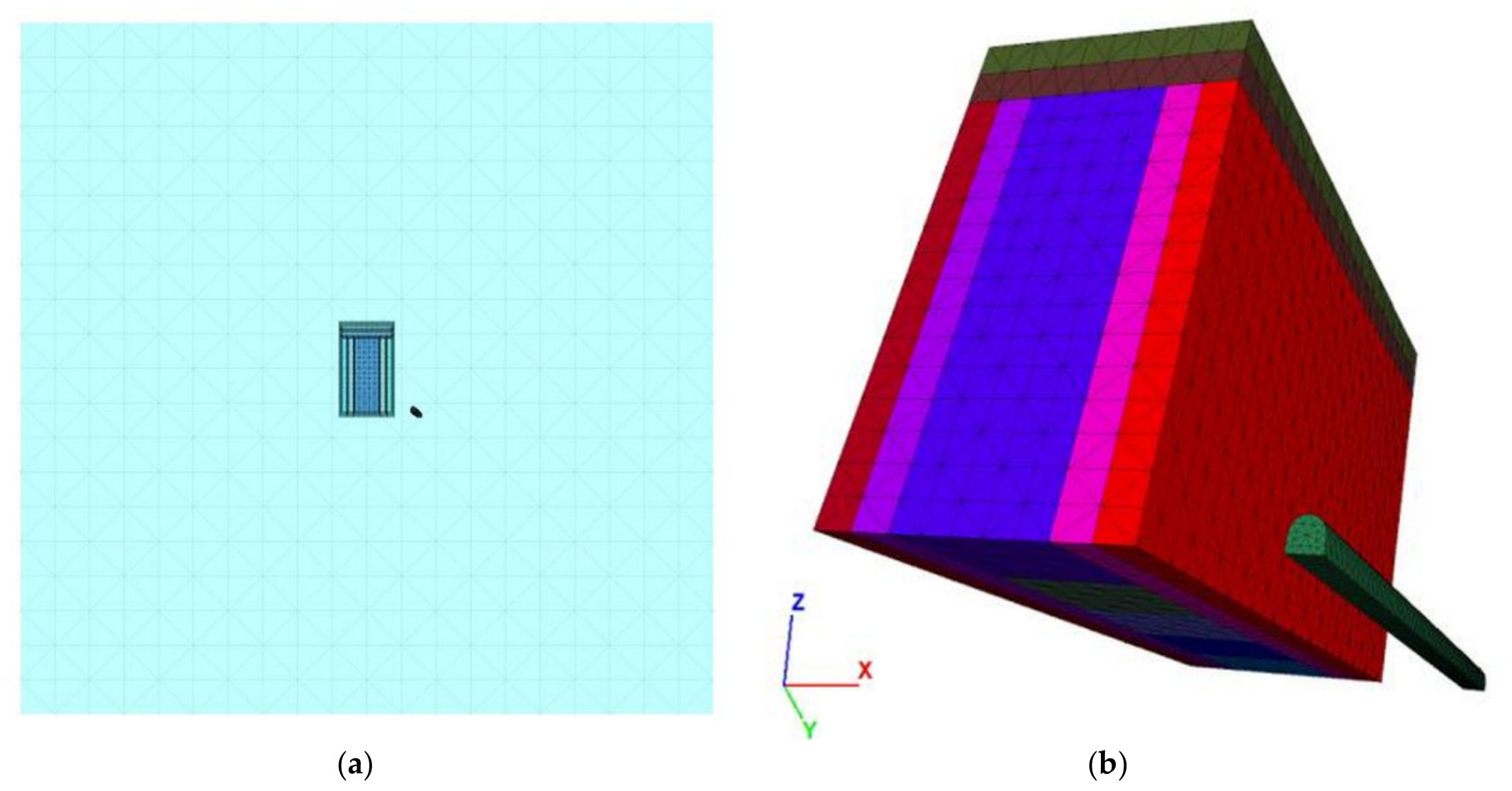
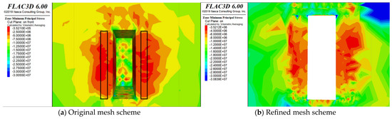
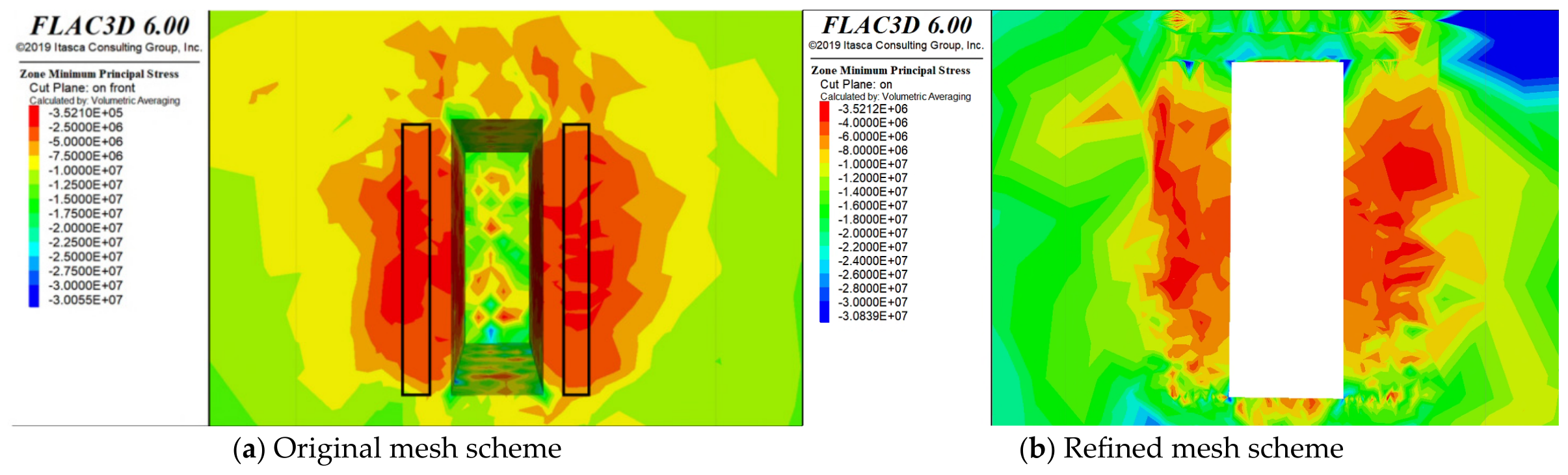
According to Saint-Venant’s principle, 3–5 times the excavation radius is widely adopted for the model boundary in numerical analysis. According to Wang et al. [33] the computational model domain is set to 1000 m × 1000 m × 1000 m, as shown in Figure 5. A horizontal in situ stress equal to 0.5 times the rock self-weight stress is applied in the horizontal direction of the model. The orebody was divided into five stoping units to simulate a subsequent backfilling process in which ore rooms 1, 3, and 5 were mined and backfilled in the first step, and pillars 2 and 4 were recovered and backfilled in the second step. A 5 m wide weakened zone was set 5 m outside the east and west sides of the orebody to simulate hydraulic-fracturing shielding. A 5 m high weakened zone was set 5 m above the roof to simulate blasting pressure relief. In the full-process model, a semi-circular arched orebody-strike roadway was set at the stope bottom to analyze the influence of stope disturbance on the underlying roadway. The stope region was discretized with a mesh size of 1 m, whereas the surrounding rock zone adopted a mesh size of 5 m. Specifically, a gradient transition zone is automatically created between the 1 m roadway mesh and the 5 m far-field mesh, where the element size increases gradually from 1 m to 5 m. The numerical model generates a total of 590,954 zones. The calculation results from refined mesh schemes are compared, as shown in Figure 6. The relative error of key results is 2.61%, which demonstrates that the numerical results are mesh-independent. During model generation, FLAC3D has a built-in function for automatically detecting the maximum unbalanced force. At each iterative calculation step, a variable outputs the maximum unbalanced-force value among all nodes within the model. This magnitude reflects the equilibrium state of the model. Calculation equilibrium is achieved when the ratio of maximum unbalanced force to the average internal force falls below 10−5.
Figure 5.
Full-process numerical model of the Support–Shielding–Destressing–Backfill system. (a) Overall model. (b) The orebody and the roadway are located in a localized area.
Figure 6.
Comparison of key indicators for mesh-independence verification between the base mesh scheme and locally refined mesh scheme.
3.2. Comparison of Single-Technology Effects
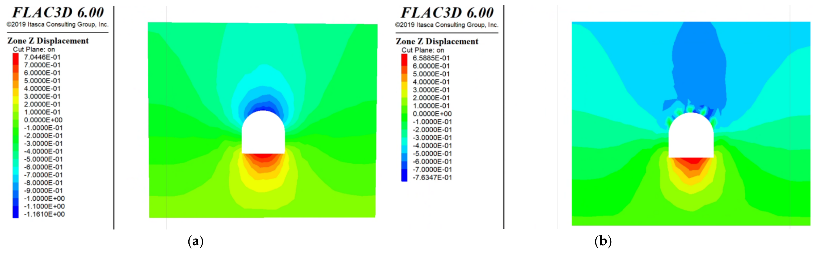
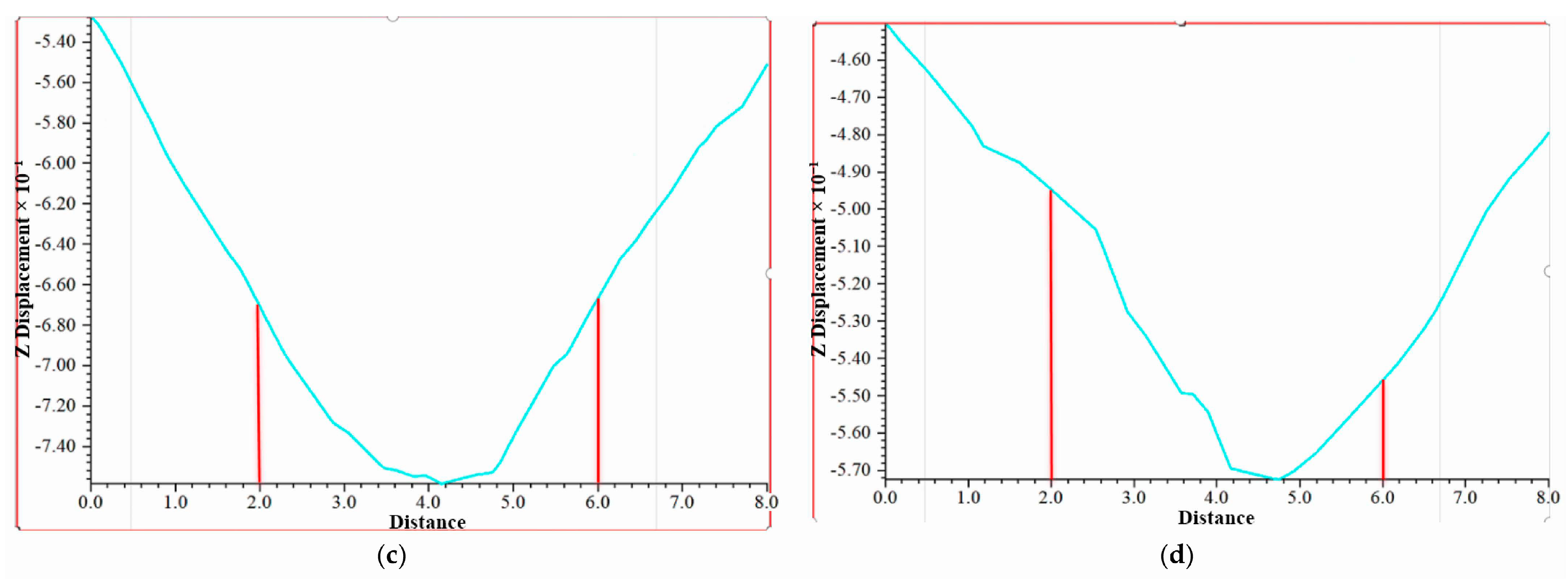
Figure 7 shows the numerical simulation results of rock-bolt support.
Figure 7.
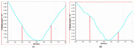
Comparison of simulated support-technology effects. (a) Z-direction displacement contour of unsupported section. (b) Z-direction displacement contour of bolt-supported section. (c) Displacement monitoring line for unsupported roof. (d) Displacement monitoring line for bolt-supported roof.
Bolt support mainly improves the state of the shallow surrounding rock of the roadway, reducing the maximum subsidence of the roadway section from 1.16 m to 0.76 m, a section-displacement reduction of about 34%. The roof displacement along the monitoring line decreases by 13.63%. This result indicates that bolts can effectively suppress early deformation after excavation, but single-layer support has limited long-term control capability under deep high-stress conditions.
Mechanistically, the bolts connect the loosened near-boundary rock to more stable material and provide radial confinement through the plates and pretension. This promotes coordinated deformation of the bolted rock mass and helps delay separation and local instability. These effects explain the improved excavation-stage response without implying that bolt support changes the regional in situ stress field.
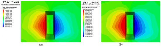
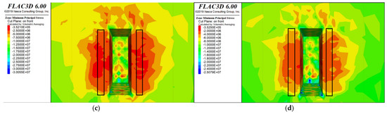
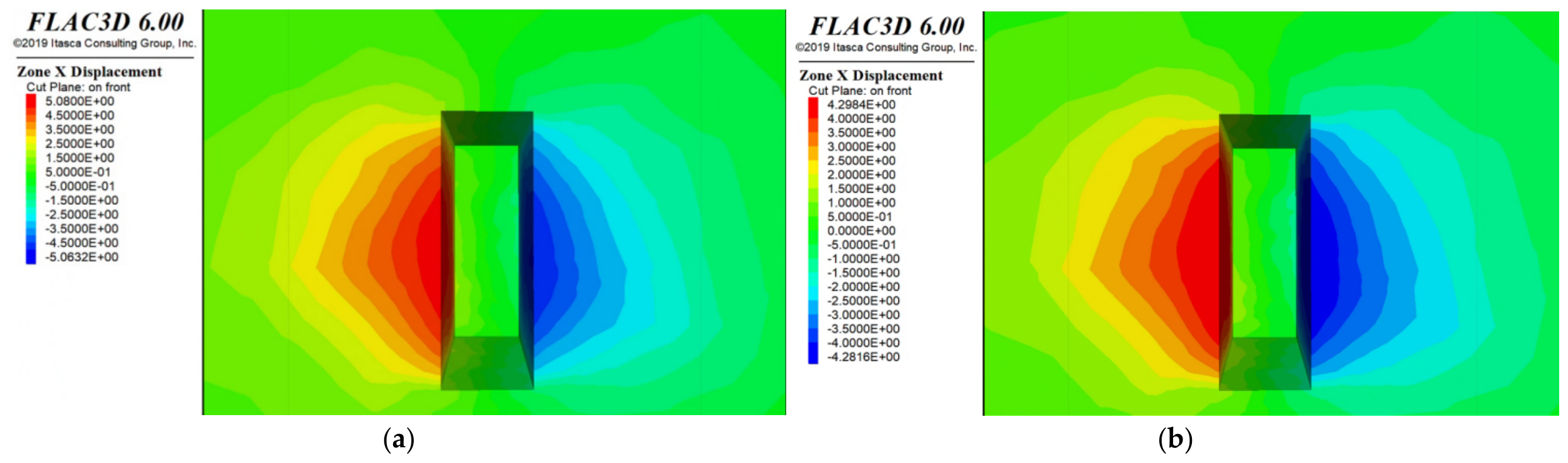
Figure 8 shows the numerical simulation results of hydraulic fracturing. After hydraulic-fracturing shielding, the x-direction displacement of the stope decreases from 5.00 m to 4.29 m, a reduction of about 14.2%. The maximum principal stress in the stope decreases from 30 MPa to 25 MPa, a reduction of about 16.6%. The contour plots show that the high-stress zone migrates from the lateral side of the stope to the outer side of the fractured zone, demonstrating that the lateral fractured zone provides stress blocking and energy dissipation.
Figure 8.
Comparison of simulated shielding-technology effects. (a) X-direction displacement of the control-group stope. (b) X-direction displacement of the shielding-group stope. (c) Maximum principal stress contour of the control group. (d) Maximum principal stress contour of the shielding group.
This index is based on the stress reduction factor in Q system (Barton’s classification) and defined as the ratio of UCS of rock to the maximum principal in situ stress [34,35] as follows:
where is uniaxial compressive strength of the rock and is the maximum in situ stress. Table 2 presents the rockburst classification based on the mean stress index.
Table 2.
Rockburst intensity based on the Tao discriminant index.
The uniaxial compressive strength of the orebody investigated in this paper is 142 MPa. After adopting the hydraulic fracturing technique, the parameter increases from 4.73 to 5.68, and the rockburst risk level decreases from moderate rockburst to weak rockburst.
Large-scale artificial fracture networks are created in preset areas on both sides of the orebody through high-pressure hydraulic fracturing, forming fractured zones in which the elastic modulus, cohesion, internal friction angle, and other mechanical parameters of the rock mass are greatly reduced. The bearing capacity of the rock mass is significantly weakened, so it cannot transmit high levels of tectonic stress. This fractured zone is equivalent to a “stress-isolation barrier” between the stope and the external high-stress rock mass. It prevents mining-induced high concentrated stress from being transmitted into the stope and adjacent roadway, forcing it to migrate to the deeper stable rock mass outside the fractured zone and thereby fundamentally reducing stress concentration around the stope. During high-pressure hydraulic fracturing, the propagation and coalescence of fractures driven by high-pressure water dissipate a large amount of elastic strain energy accumulated in the rock mass in advance. At the same time, the fracture network formed by fracturing provides a continuous dissipation channel for energy released by surrounding-rock deformation during subsequent mining; sliding and friction along fracture surfaces continuously absorb energy, greatly reducing releasable elastic energy in the rock mass and effectively suppressing dynamic disasters such as rockbursts. The fractured zone formed by hydraulic fracturing is equivalent to setting a flexible “yielding cushion” on both sides of the stope. Its good plastic deformability allows it to continuously absorb surrounding-rock deformation during mining through its own compression, buffer the dynamic impact of high stress on the stope and roadway, and achieve the control objective of “pressure relief without loss of stability.”
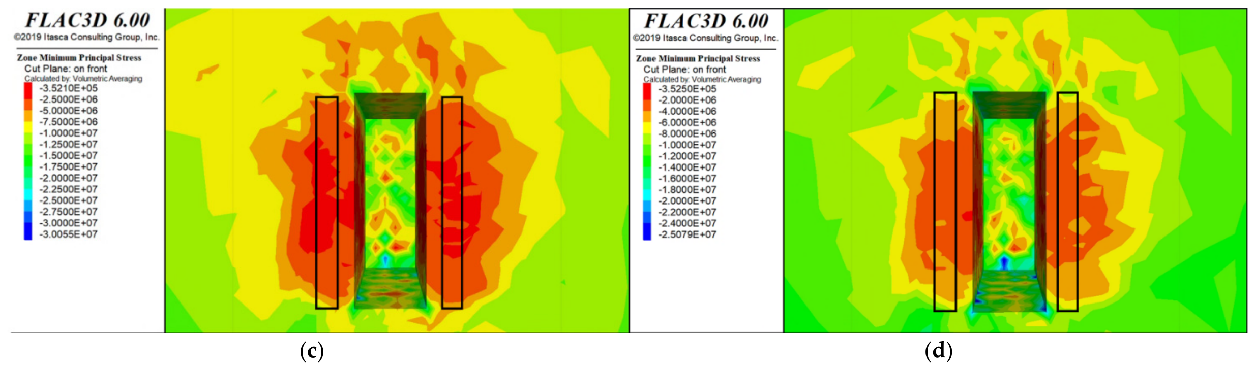
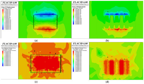
Figure 9 shows the numerical simulation results of roof blasting. Roof blasting destress balsting reduces the stope roof downward displacement from 4.4 m to 3.8 m, a reduction of about 13.6%, and reduces the maximum principal stress from 55 MPa to 45 MPa, a reduction of about 18.2%. This shows that destress balsting can destroy the continuity of a thick and hard roof and reduce stress concentration in the immediate roof, but its action dimension is mainly concentrated in the roof and cannot independently solve lateral rock-pillar stress or mined-out-area support problems.
Figure 9.
Simulated effect of destress blasting technology. (a) Z-direction displacement contour of the control group. (b) Z-direction displacement contour of the destress blasting group. (c) Maximum principal stress contour of the control group. (d) Maximum principal stress contour of the destress blasting group.
The roof fractured zone formed by destress balsting releases in advance the high stress accumulated in the roof strata. At the same time, the high stress originally concentrated in the immediate roof of the mined-out area migrates to the deeper stable strata above the fractured zone, greatly reducing the stress concentration coefficient of the mined-out-area roof and reducing roof bending subsidence and development of the plastic zone in the stope surrounding rock. The strength and elastic modulus of the rock mass in the blasting fractured zone are greatly reduced, forming a weak “destress balsting cushion.” On the one hand, this cushion coordinates roof subsidence through its own compression and buffers dynamic impacts from roof-strata movement on the stope and underlying roadway. On the other hand, the fracture network generated by blasting provides a continuous dissipation channel for energy released by rock-mass deformation; fracture propagation and sliding friction absorb a large amount of elastic strain energy and reduce the rock mass’s impact tendency.
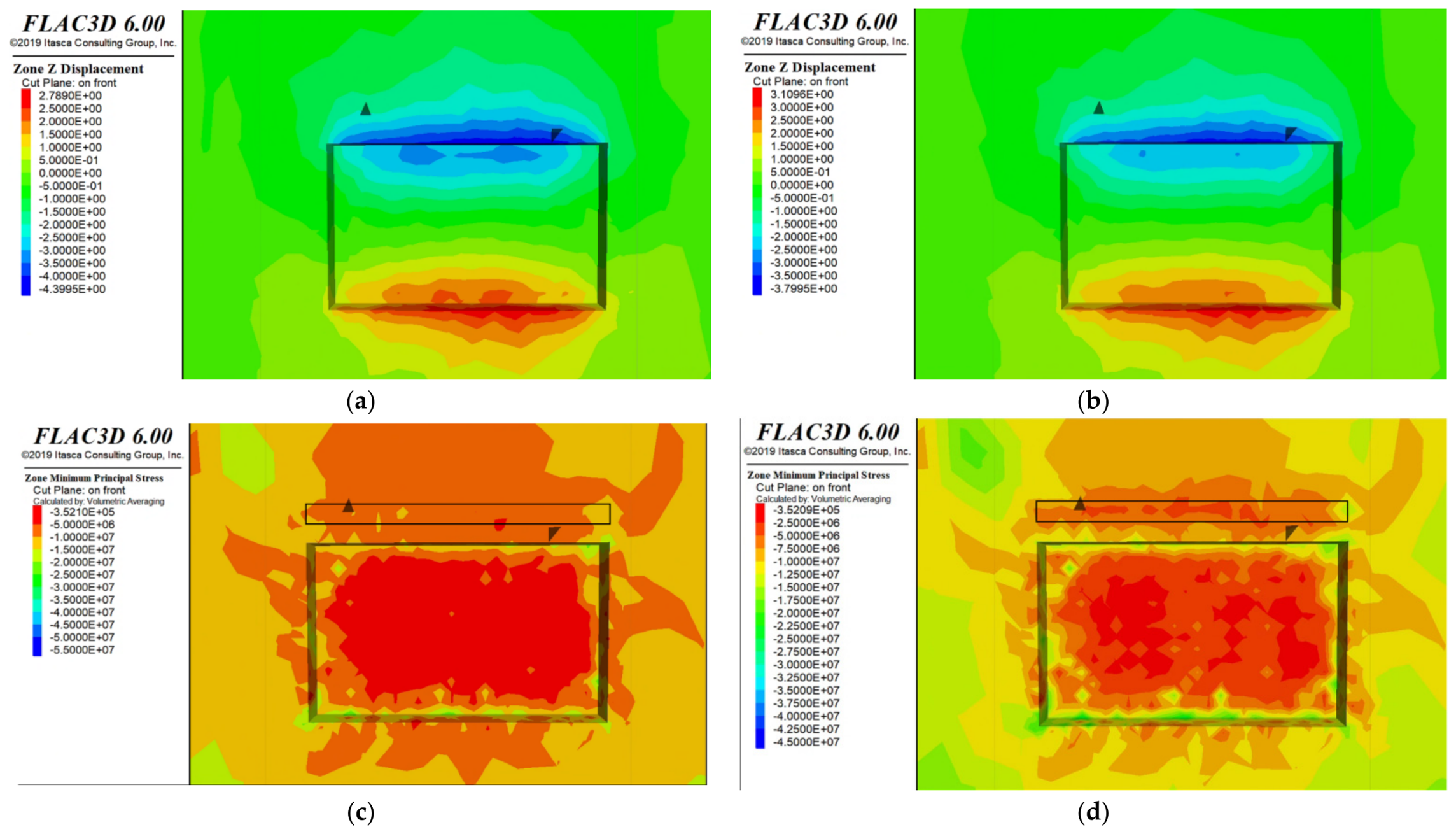
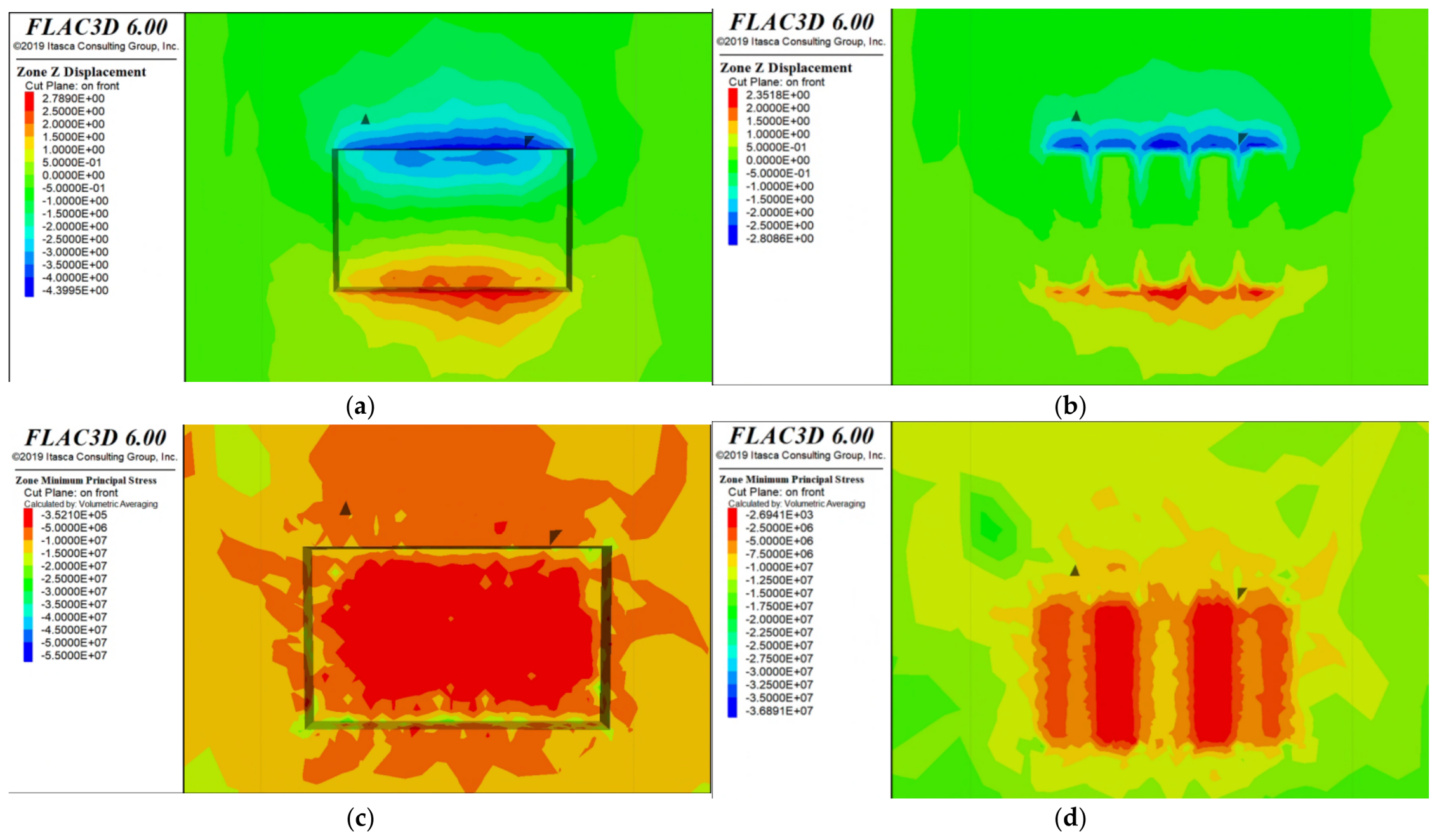
Figure 10 shows the numerical simulation results of subsequent backfill. After subsequent backfilling, the maximum roof subsidence decreases from 4.4 m to 2.8 m, a reduction of 36.4%, and the maximum principal stress in the stope decreases from 55 MPa to 36.7 MPa, a reduction of 34%. This is the most significant deformation-control effect among the single technologies, because the backfill body both bears part of the load and provides continuous restraint to the surrounding rock.
Figure 10.
Simulated effect of backfilling technology. (a) Z-direction displacement contour of the control group. (b) Z-direction displacement contour of the backfilling group. (c) Maximum principal stress contour of the control group. (d) Maximum principal stress contour of the backfilling group.
Once hardened, the backfill carries part of the transferred load and restrains convergence of the stope boundaries. This reduces the unsupported void volume and moderates stress redistribution during subsequent extraction. The result is consistent with the arching and composite-stiffness mechanisms described in Section 2.4; long-term performance nevertheless depends on the actual backfill strength, curing history, interfaces, and mining sequence.
3.3. Combined Technology and Full-Process Protection Effect
Figure 11 shows the full-process numerical simulation results.
Figure 11.
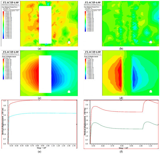
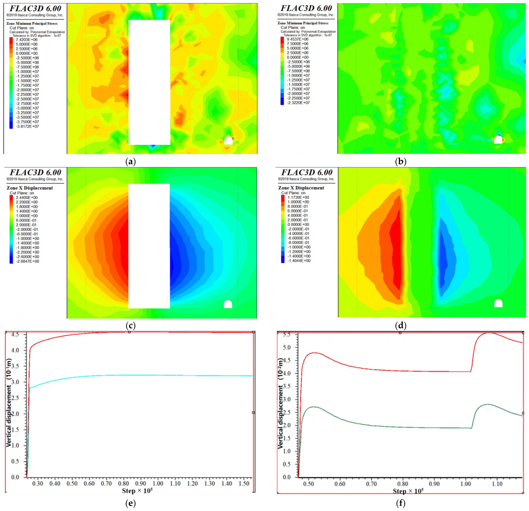
Simulated effect of the Support–Shielding–Destressing–Backfill technology. (a) Maximum principal stress contour of the control group. (b) Maximum principal stress contour of the Support–Shielding–Destressing–Backfill group. (c) X-direction displacement contour of the control group. (d) X-direction displacement contour of the Support–Shielding–Destressing–Backfill group. (e) Vertical displacement of roadway roof in the control group. (f) Roof vertical displacement of the Support–Shielding–Destressing–Backfill group.
The full-process combined protection technology further incorporates roadway support into the mining chain and directly protects the orebody-strike roadway. Under unprotected conditions, extraction of the upper stope increases the roof subsidence of the underlying roadway from 0.15 m in the excavation stage to 0.40 m. After full-process protection is adopted, roof subsidence is controlled at 0.047 m in the excavation stage and increases only to 0.055 m after mining. Compared with the unprotected group, the reduction is about 63% in the excavation stage, reaches 96.8% in the stage of superposed stope disturbance, and reduces total roadway roof subsidence by 86.25%. This shows that the full-process technology not only reduces the stope stress level, but also significantly weakens the transmission of stope disturbance to the underlying roadway through backfill isolation and roadway support.
This result fully verifies the active reinforcement effect of bolt support. Through pretension, it improves the stress state of the roadway surrounding rock, enhances the self-bearing capacity of the surrounding rock, effectively suppresses early deformation after roadway excavation, and lays the foundation for roadway stability during subsequent mining. Under unprotected conditions, the strong superposed disturbance induced by extraction of the upper orebody increases roadway roof subsidence sharply to 0.4 m, 2.67 times that in the excavation stage. This fully indicates that stope mining disturbance is the core cause of large deformation and instability of deep orebody-strike roadways. In the Support–Shielding–Destressing–Backfill group, pre-pressure-relief technology before mining fundamentally reduces the stress level of mining disturbance, and subsequent backfilling during mining effectively isolates the transmission of stope deformation to the underlying roadway. Consequently, after orebody extraction, roadway roof subsidence increases only to 0.055 m. Compared with the unprotected group, the reduction reaches 96.8%, almost completely eliminating the influence of stope mining on the roadway and verifying the super-synergistic prevention and control effect of the full-process technology.
The full-process combined protection technology reduces total roadway roof subsidence by 86.25%, and the protection effect shows a clear gradient: full-process Support–Shielding–Destressing–Backfill technology (86.25%) > single subsequent backfilling technology (36.4%) > single roof destress blasting technology (18.2%) > single hydraulic-fracturing shielding technology (16.6%) > single-layer bolt-support technology (13.63%) and 36.4 + 18.2 + 16.6 + 13.63 = 84.83 < 86.25. This result fully proves that the protection effect of the full-process combined technology is far superior to that of single technologies and local combined technologies, realizing a superimposed synergistic enhancement effect of 1 + 1 + 1 + 1 > 4.
This technology comprehensively meets the ground-pressure prevention and control requirements across the full chain, full space, and full cycle of deep high-stress metal-mine extraction. It both compensates for the dimensional shortcomings of single technologies and realizes temporal coordination and functional complementarity among the technologies. From the two core dimensions of “load reduction” and “bearing-capacity enhancement,” it solves the core problems of large surrounding-rock deformation and dynamic-disaster prevention and control under deep high-stress conditions, and provides a complete and scientific technical scheme for safe, efficient, and green mining of deep metal mines.
3.4. Engineering Criteria for System Parameter Selection
To translate the proposed combined protection technology into an engineering design procedure, the parameters of the four components should not be selected independently. They should be determined from the measured in situ stress, roadway and stope geometry, rock-mass strength and deformability, fracture characteristics, blasting conditions, and backfill properties, and then verified through a coupled numerical model. The theoretical relations established in Section 2.1, Section 2.2, Section 2.3 and Section 2.4 provide the governing constraints, whereas the numerical parameters adopted in this study should be regarded as initial reference values rather than universal constants.
3.4.1. Prestressed Bolt and Plate Support
The design objective is to provide sufficient active confinement to suppress the shallow plastic zone while ensuring that the anchorage remains in stable rock. According to Equations (1)–(6), bolt pretension, row spacing and circumferential spacing should be jointly selected from the required boundary support pressure; the plate efficiency factor may be taken within 0.70–0.95 according to contact quality. Bolt length should satisfy the requirement that the anchorage extends beyond the calculated plastic-zone boundary, and the grouted length should not be smaller than the critical load-transfer length. For preliminary calibration under conditions comparable to the present model, a pretension of 100 kN may be used as a starting value, but it should be increased or the spacing reduced when monitoring or numerical analysis indicates an excessive plastic-zone radius or roof convergence.
3.4.2. Hydraulic-Fracturing Stress Shielding
The fracturing pressure must first satisfy the fracture-initiation criterion in Equation (7), and sustained propagation should satisfy the fracture-toughness condition in Equation (8). After initiation, fracture density, connectivity, weakened-zone width and stand-off distance should be adjusted to obtain a sufficiently low stress-transmission coefficient according to Equations (9)–(12), while avoiding direct hydraulic or mechanical damage to the protected roadway. The present numerical model used a 5 m wide weakened zone located 5 m outside each side of the orebody; these dimensions are recommended only as an initial trial configuration for similar geometries and should be recalibrated with site-specific stress orientation, permeability, jointing and water-control requirements.
3.4.3. Roof Destress Blasting
Burden, spacing, charge conditions and blasthole diameter should be designed so that adjacent damaged zones overlap to form a continuous pressure-relief barrier rather than isolated damaged pockets. The fragmentation/damage coefficient in Equation (14) is typically 0.3–0.7 for hard rock, and the equivalent damaged radius should be checked with Equation (15). The effective destressed-zone height is generally 3–8 m according to the theoretical model; the 5 m high zone positioned 5 m above the roof in the numerical study can therefore serve as a preliminary reference. The final layout should be accepted only when the predicted roof stress reduction is achieved without producing unacceptable abutment stress concentration or blast damage to adjacent excavations.
3.4.4. Cemented Paste Backfill
Backfill parameters should be selected from both short-term exposure stability and long-term regional stress-control requirements. The required compressive strength should satisfy Equation (24) with a safety factor of 1.3–1.5, while the curing-dependent strength should be checked using Equation (23). For tailings-based CPB with 4–7% binder, the hydration exponent used in the present framework is typically 0.3–0.5. The filling sequence and curing time should ensure that the backfill has attained the required strength before adjacent or secondary stopes are exposed, and the backfill modulus and volume ratio should be checked through Equation (25) to limit long-term stress transfer.
3.5. Comparison with Published Numerical Modeling Studies
Because field or laboratory validation is not available for the present mine configuration, the numerical outcomes were benchmarked against published studies using comparable control mechanisms. This comparison is intended as an external plausibility check rather than a one-to-one validation, because the cited studies differ in excavation geometry, stress level, rock-mass properties, support parameters, and response indices.
For active support, the present model predicts a 34% reduction in the maximum roadway-section subsidence (1.16 to 0.76 m), while the roof monitoring-line displacement decreases by 13.63%. Ref. [15] investigated a deep mine drift using numerical simulations together with field monitoring and reported that an optimized excavation-compensation and bolt-support scheme reduced the final surrounding-rock deformation by approximately 70% relative to the original support scheme. The larger reduction than that obtained in the present bolt-only case is reasonable because the two studies differ in excavation geometry, stress environment, support configuration, and performance index.
For hydraulic fracturing, the present simulation gives a 16.6% decrease in maximum principal stress and a 14.2% decrease in lateral stope displacement. Shao et al. [36] combined numerical analysis with mine-site application and reported that hydraulic fracturing reduced the stress-concentration degree of roadway surrounding rock by approximately 26%; the subsequent field application reduced roadway surrounding-rock deformation by more than 60%. Although their geological setting and fracturing layout differ from those of the present metal-mine model, both studies show the same stress-transfer tendency after hydraulic fracturing.
For destress blasting, the present simulation gives an 18.2% reduction in maximum principal stress and a 13.6% reduction in roof displacement. Sainoki et al. [37] examined destress blasting for deep mine drift development using three-dimensional FLAC3D models. Their comparison showed that a traditional representation with a uniformly distributed blast-induced damage zone can provide an overly optimistic estimate of destress-blasting efficiency relative to a model that represents the damage zone around individual blastholes. This observation is directly relevant to the equivalent weakened-zone representation adopted in the present model. Accordingly, the calculated 18.2% stress reduction should be interpreted as a model- and configuration-dependent prediction rather than a field-validated value.
For cemented backfill, the present model predicts a 34% reduction in maximum principal stress and a 36.4% reduction in roof subsidence. Chang et al. [38] used FLAC3D to investigate a cemented-paste-backfill false roof and found that increasing CPB strength from 0.5 to 1.5 MPa reduced the vertical stress from 0.021 to 0.008 MPa (to approximately one-third of the original level) and reduced average vertical displacement from 6.8 to 4.4 mm (about 35%). Thus, the stress-reduction and deformation-control trends in the present backfill model are consistent with published numerical observations, while the absolute magnitudes remain dependent on geometry, constitutive parameters, and loading conditions.
No published study with the same SSDB sequence and identical geometry was identified; therefore, the 86.25% combined roadway-subsidence reduction should be regarded as a model-based prediction of synergistic potential rather than externally validated engineering performance.
4. Conclusions
(1) Deep high-stress mine extraction faces multi-source coupled problems such as roadway deformation, stope stress concentration, roof dynamic disasters, and instability of surrounding rock in mined-out areas. Its essence is the contradiction between high in situ stress loads and insufficient bearing capacity of the surrounding rock.
(2) Each single technology has a clear targeted prevention and control function: bolt support is suitable for controlling early deformation after roadway excavation; hydraulic-fracturing shielding is suitable for blocking lateral stress transfer; roof destress blasting is suitable for weakening stress concentration in thick and hard roofs; and subsequent backfilling is suitable for limiting long-term deformation of mined-out areas. However, the action range of a single technology is limited and cannot satisfy the full-space and full-cycle prevention and control requirements of deep mining.
(3) The full-process combined protection technology integrates active roadway support, stope pre-pressure relief, stepwise stoping, and post-mining backfilling. It reduces total roadway roof subsidence by 86.25% and is particularly effective in suppressing the superposed disturbance caused by stope extraction. It is therefore a comprehensive prevention and control scheme suitable for safe and efficient mining of deep high-stress metal mines.
(4) The conclusions are limited to one numerical configuration. Equivalent weakened zones are used for hydraulic fracturing and blasting, and no field/laboratory validation is included. The comparison in Section 3.5 shows that the predicted deformation- and stress-reduction trends are qualitatively consistent with published numerical studies of bolt support, hydraulic fracturing, destress blasting, and cemented backfill, while the reported magnitudes vary with site conditions and modeling assumptions. This external comparison provides a plausibility check but does not replace site-specific validation. Future work should calibrate the weakened-zone parameters and the combined-system response against field monitoring, microseismic data, borehole/fracture mapping, and/or physical-model tests before the method is used as a site-specific design or rockburst-safety criterion.
Author Contributions
Conceptualization, T.L. and S.Z.; formal analysis, Q.Z. and T.L.; writing—original draft, Z.S.; writing—review and editing, T.L. and Q.Z. All authors have read and agreed to the published version of the manuscript.
Funding
This work was financially supported by the National Natural Science Foundation of China under Grant No. 52374108.
Data Availability Statement
Data are contained within the article.
Conflicts of Interest
Shankun Zhao, Qifan Zeng, Zhenguo Su and Taoying Liu were employed by Coal Science and Technology Research Institute Co., Ltd.
References
- Wagner, H. Deep mining: A rock engineering challenge. Rock Mech. Rock Eng. 2019, 52, 1417–1446. [Google Scholar] [CrossRef] [Scilit]
- He, M.C.; Xie, H.P.; Peng, S.P.; Jiang, Y.D. Study on rock mechanics in deep mining engineering. Chin. J. Rock Mech. Eng. 2005, 24, 2803–2813. [Google Scholar]
- Kaiser, P.K.; Cai, M. Design of rock support system under rockburst condition. J. Rock Mech. Geotech. Eng. 2012, 4, 215–227. [Google Scholar] [CrossRef] [Scilit]
- Mazaira, A.; Konicek, P. Intense rockburst impacts in deep underground construction and their prevention. Can. Geotech. J. 2015, 52, 1426–1439. [Google Scholar] [CrossRef] [Scilit]
- Feng, X.; Chen, B.; Li, S.; Zhang, C.; Xiao, Y.; Feng, G.; Zhou, H.; Qiu, S.; Zhao, Z.; Yu, Y.; et al. Studies on the evolution process of rockbursts in deep tunnels. J. Rock Mech. Geotech. Eng. 2012, 4, 289–295. [Google Scholar] [CrossRef] [Scilit]
- Hoek, E.; Brown, E.T. The Hoek–Brown failure criterion and GSI—2018 edition. J. Rock Mech. Geotech. Eng. 2019, 11, 445–463. [Google Scholar] [CrossRef] [Scilit]
- Hudyma, M.; Potvin, Y. An engineering approach to seismic risk management in hard rock mines. Rock Mech. Rock Eng. 2010, 43, 891–906. [Google Scholar] [CrossRef] [Scilit]
- Stillborg, E.B. Professional Users Handbook for Rock Bolting; Trans Tech Publications: Wollerau, Switzerland, 1985. [Google Scholar]
- Windsor, C.R.; Thompson, A.G. Rock reinforcement—Technology, testing, design and evaluation. In Comprehensive Rock Engineering; Pergamon Press: Oxford, UK, 1993; Volume 4, pp. 451–484. [Google Scholar]
- Cai, M.; Kaiser, P.K. Volume I: Rockburst Phenomenon and Support Characteristics. In Rockburst Support Reference Book; MIRARCO: Sudbury, ON, Canada, 2018. [Google Scholar]
- Andrieux, P.P.; Brummer, R.K.; Liu, Q.; Simser, B.P.; Mortazavi, A. Large-scale panel destress blast at Brunswick mine. CIM Bull. 2003, 96, 78–87. [Google Scholar]
- Huang, B.; Liu, J.; Zhang, Q. The reasonable breaking location of overhanging hard roof for directional hydraulic fracturing to control strong strata behaviors of gob-side entry. Int. J. Rock Mech. Min. Sci. 2018, 103, 1–11. [Google Scholar] [CrossRef] [Scilit]
- He, H.; Dou, L.M.; Gong, S.Y.; He, J.; Zheng, Y.; Zhang, X. Microseismic and electromagnetic coupling method for coal bump risk assessment. Saf. Sci. 2020, 125, 104634. [Google Scholar] [CrossRef] [Scilit]
- He, M.C.; Gong, W.L.; Wang, J.; Qi, P.; Tao, Z.; Du, S.; Peng, Y. Development of a novel energy-absorbing bolt with extraordinarily large elongation and constant resistance. Int. J. Rock Mech. Min. Sci. 2014, 67, 29–42. [Google Scholar] [CrossRef] [Scilit]
- Guo, L.; Tao, Z.; He, M.; Coli, M. Excavation compensation and bolt support for a deep mine drift. J. Rock Mech. Geotech. Eng. 2024, 16, 3206–3220. [Google Scholar] [CrossRef] [Scilit]
- Guo, K.; Ji, M.; Liu, Y.; Wang, Q.; Guo, Z.; Peng, J. Study on the load-bearing mechanism of tensile prestressed bolt–cable coupled support in deep roadways. Appl. Sci. 2025, 15, 12418. [Google Scholar] [CrossRef] [Scilit]
- Tao, Z.; Zhu, C.; He, M.; Karakus, M. A physical modeling-based study on the control mechanisms of negative Poisson’s ratio anchor cable on the large deformation of tunnels. Rock Mech. Rock Eng. 2021, 55, 4027–4048. [Google Scholar]
- He, M.C.; Li, C.; Gong, W.L.; Sousa, L.; Li, S. Dynamic tests for a constant-resistance-large-deformation bolt using a modified SHTB system. Tunn. Undergr. Space Technol. 2017, 64, 103–116. [Google Scholar] [CrossRef] [Scilit]
- Kumar, S.; Mishra, A.K.; Choudhary, B.S. Prediction of back break in blasting using random decision trees. Eng. Comput. 2022, 38, 1185–1191. [Google Scholar] [CrossRef] [Scilit]
- Benzaazoua, M.; Fall, M.; Belem, T. A contribution to understanding the hardening process of cemented pastefill. Miner. Eng. 2004, 17, 141–152. [Google Scholar] [CrossRef] [Scilit]
- Li, L.; Aubertin, M. Numerical investigation of the stress state in inclined backfilled stopes. Int. J. Geomech. 2009, 9, 52–62. [Google Scholar] [CrossRef] [Scilit]
- Xie, X.; Wang, W. Numerical simulation-based study on the arching effect in subsequent backfill. Appl. Sci. 2025, 15, 5649. [Google Scholar] [CrossRef] [Scilit]
- Mark, C. Design of roof bolt systems. In Proceedings: New Technology for Coal Mine Roof Support; NIOSH Open Industry Briefing, NIOSH IC; NIOSH: Washington, DC, USA, 2000; pp. 111–132. [Google Scholar]
- Cai, M. Principles of rock support in burst-prone ground. Tunn. Undergr. Space Technol. 2013, 36, 46–56. [Google Scholar] [CrossRef] [Scilit]
- Konicek, P.; Soucek, K.; Stas, L.; Singh, R. Long-hole destress blasting for rockburst control during deep underground coal mining. Int. J. Rock Mech. Min. Sci. 2013, 61, 141–153. [Google Scholar] [CrossRef] [Scilit]
- Kang, H.; Xia, Y.; Feng, M.; Lu, C.; Gao, F. Case study of hydraulic fracturing for coal burst risk mitigation. Int. J. Coal Sci. Technol. 2025, 12, 61. [Google Scholar] [CrossRef] [Scilit]
- Fenner, R. Untersuchungen zur Erkenntnis des Gebirgsdruckes. Glückauf 1938, 74, 681–695. [Google Scholar]
- Kastner, H. Statik des Tunnel-und Stollenbaues auf der Grundlagen Geomechanischer Erkenntnisse; Springer: Berlin/Heidelberg, Germany, 2013. [Google Scholar]
- Farmer, I.W. Stress distribution along a resin grouted rock anchor. Int. J. Rock Mech. Min. Sci. Geomech. Abstr. 1975, 12, 347–351. [Google Scholar] [CrossRef] [Scilit]
- Li, C.; Stillborg, B. Analytical models for rock bolts. Int. J. Rock Mech. Min. Sci. 1999, 36, 1013–1029. [Google Scholar] [CrossRef] [Scilit]
- Li, L.; Aubertin, M. A three-dimensional analysis of the stress distribution in backfilled stopes with vertical and inclined walls. Can. Geotech. J. 2009, 46, 1430–1446. [Google Scholar]
- Mitchell, R.J. Model studies on the stability of confined fills. Can. Geotech. J. 1989, 26, 210–216. [Google Scholar] [CrossRef] [Scilit]
- Wang, Y.; Jin, A. Research on Optimization of Orebody Mining Sequence Under Isolation Layer of Filling Body Based on FLAC3D Software. Processes 2025, 13, 2296. [Google Scholar] [CrossRef] [Scilit]
- Grimstad, E. Experiences from excavation under high rock stress in the 24, 5 km long Laerdal Tunnel. In Proceedings of the International Conference on Rock Engineering Techniques for Site Characterization, Bangalore, India, 6–8 December 1999; pp. 135–146. [Google Scholar]
- Tao, Z.-Y. Support design of tunnels subjected to rockbursting. In ISRM International Symposium; ISRM: Lisbon, Portugal, 1988; p. ISRM-IS. [Google Scholar]
- Shao, L.; Huang, B.; Zhao, X.; Chen, S. Hydraulic fracturing method for relieving stress concentration in remaining coal pillar in overlying goaf. Energy Sci. Eng. 2024, 12, 1518–1530. [Google Scholar] [CrossRef] [Scilit]
- Sainoki, A.; Emad, M.Z.; Mitri, H.S. Study on the efficiency of destress blasting in deep mine drift development. Can. Geotech. J. 2017, 54, 518–528. [Google Scholar] [CrossRef] [Scilit]
- Chang, Q.; Sun, X.; Dong, X.; Shao, S. Stability analysis of cemented paste backfill false roof in highwall mining: A case study. Desalin. Water Treat. 2021, 219, 96–102. [Google Scholar] [CrossRef] [Scilit]

Disclaimer/Publisher’s Note: The statements, opinions and data contained in all publications are solely those of the individual author(s) and contributor(s) and not of MDPI and/or the editor(s). MDPI and/or the editor(s) disclaim responsibility for any injury to people or property resulting from any ideas, methods, instructions or products referred to in the content. |
© 2026 by the authors. Licensee MDPI, Basel, Switzerland. This article is an open access article distributed under the terms and conditions of the Creative Commons Attribution (CC BY) license.