


Abstract
The dynamic behaviour of a column excited at the base, e.g., under an earthquake load, has been extensively studied. However, the column may also experience impact at the tip like a heavy-duty truck braking on a bridge. The caused base shear of the pier is very important. In this work, the dynamic behaviour, particularly the impact load from the tip to the base, was studied on two different composites: double basalt- and double flax fibre-reinforced polymer tube (DBFRP and DFFRP)-confined coconut fibre-reinforced concrete (CFRC). For each composite, two columns with a height of 1 m, an inner diameter of the outer tube of 100 mm, and an inner tube of 30 mm were fabricated. The column was fully fixed at the base and struck at the top with an impulse hammer. The base shear was calculated through an equivalent mass method using the acceleration at the tip. The results show that both DBFRP-CFRC and DFFRP-CFRC can dissipate a portion of the impact force, resulting in a reduction in force at the base of the specimens. The base shear of DFFRP-CFRC columns is larger and dissipates energy faster than that of DBFRP-CFRC columns.
1. Introduction
In recent years, fibre-reinforced polymer (FRP) composites have been extensively studied and used. Due to high stiffness and outstanding corrosion resistance, synthetic fibres such as glass, carbon and aramid fibres are frequently used in the construction industry [1]. However, the production of synthetic fibre is expensive and associated with various environmental issues. As more and more environmental concerns are raised, it is urgent for the construction industries to develop sustainable construction materials, i.e., the usage of raw materials (e.g., coir) and natural FRP composites such as basalt fibre. These materials are environmentally friendly and can be applied to concrete structures.
Coir is extracted from coconut shells and has outstanding mechanical properties. Ramakrishna and Sundararajan [2] compared the impact performance of four different natural fibre (coir, sisal, jute and hibiscus cannebinus)-reinforced concretes. In comparison with plain concrete, coconut fibre-reinforced concrete (CFRC) has more randomly distributed cracks due to the fibre bridging effect at crack locations. Inclusion of coconut fibre can also improve the damping of composite material [3,4,5,6,7,8]. To improve the compression strength of CFRC, Yan and Nawawi [9,10,11,12] proposed a new material, flax FRP-confined CFRC, which can be used almost as an equivalent conventional concrete with steel reinforcement.
Existing research revealed a number of good features of BFRP and FFRP confined concrete on compression and flexural properties [13,14,15,16,17,18,19,20,21]. The dynamic properties of FFRP-reinforced concrete are also studied by many researchers. Yan [12] tested FFRP-CFRC beams under impact tests. Three vibration modes were investigated (transverse mode, longitudinal mode and torsional mode). Wang [6] investigated the FFRP thickness on the impact behaviour of reinforced CFRC and found that the impact resistance increases linearly with the FFRP thickness. Wang [22] also studied the impact behaviour of concrete slabs reinforced by externally wrapped FFRP sheets, and the results revealed that the reinforced concrete slabs can absorb more energy and withstand higher impact loads compared with normal concrete slabs. Other than single outer-FFRP reinforcement, Chen [23] studied the seismic behaviour of DFFRP-CFRC with mechanical bonds. Wu et al. [24] studied the seismic behaviour of BFRP-confined CFRC and concluded that the seismic performance of the concrete is improved significantly. A similar conclusion has been made by Zhou et al. [25]. They studied the seismic behaviour of BFRP reinforced concrete beam-column joints and concluded that the ultimate bearing capacity and energy dissipation are improved compared with unconfined specimens. Ouyang et al. [26] compared the seismic performance of CFRP- and BFRP-retrofitted square RC columns. It was demonstrated that there is a potential for BFRP composites to be used as an alternative to conventional FRPs for seismic retrofit of square RC columns. Zhao et al. [27] tested RC beams under impact load and found that with increasing beam span, the time needed for stress waves to propagate to the supports and reflect to the impact point increases accordingly, and the effect of stress wave propagation on impact response becomes more significant.
However, when vehicles are in motion or people run or jump on a beam, various impact loads are applied to the member. It is therefore important to understand the load transfer to the base or supports. Most previous research has focused on the material properties or static performance of columns or beams, while little research has addressed the dynamic responses of beams or columns under impact loading. To address this research gap, this study conducted dynamic impact tests on 1 m high cantilever BFRP-CFRC and FFRP-CFRC column specimens to investigate their dynamic properties and load transfer behaviour.
2. Experimental Study
2.1. Test Specimens and Materials
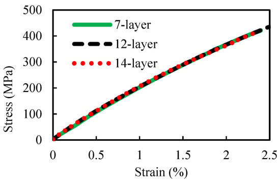
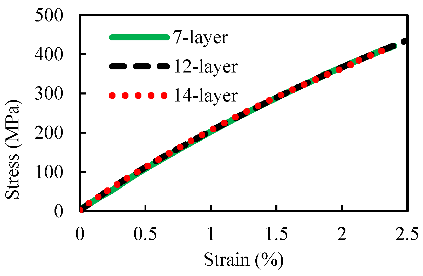
Commercial bidirectional woven basalt fabric (300 g/m2) was used. The fabric has a plain-woven structure with a count of 5.5 threads/cm in both warp and weft directions. The epoxy used was SP High Modulus Ampreg 22 resin and slow hardener with a mix ratio of 100:26 by mass. Three different configurations of layers, i.e., 7-, 12- and 14-layer of basalt fibre, with each of six coupons, were fabricated and cured. The corresponding thicknesses were 1.91 mm, 3.13 mm and 3.68 mm, respectively. Coupon tests were carried out to determine the elastic modulus and strength on a universal testing machine [28]. Figure 1 shows that the tensile strengths of 7, 12 and 14 layers were 422 MPa, 409 MPa and 435 MPa, respectively, and the corresponding fracture strains were 2.4%, 2.5% and 2.3%, respectively. The average tensile strength is 422 MPa, and the average fracture strain is 2.4%. The elastic modulus of the basalt coupon, determined from the gradient of the stress–strain curve, is about 17 GPa, in comparison to that of FFRP of 9.5 GPa [13].
Figure 1.
Stress–strain curves for different layers obtained from coupon test.
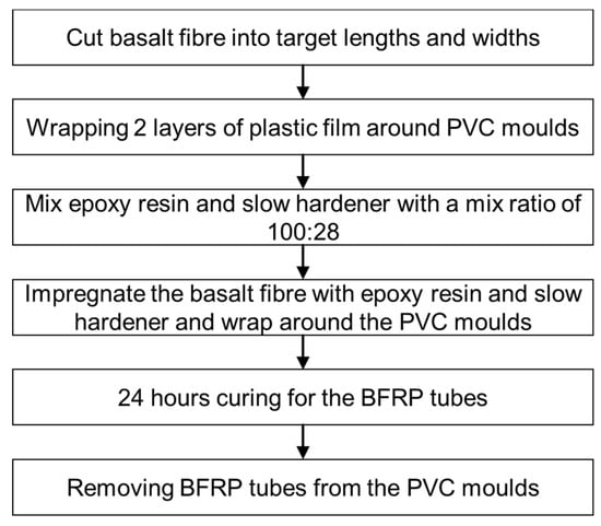
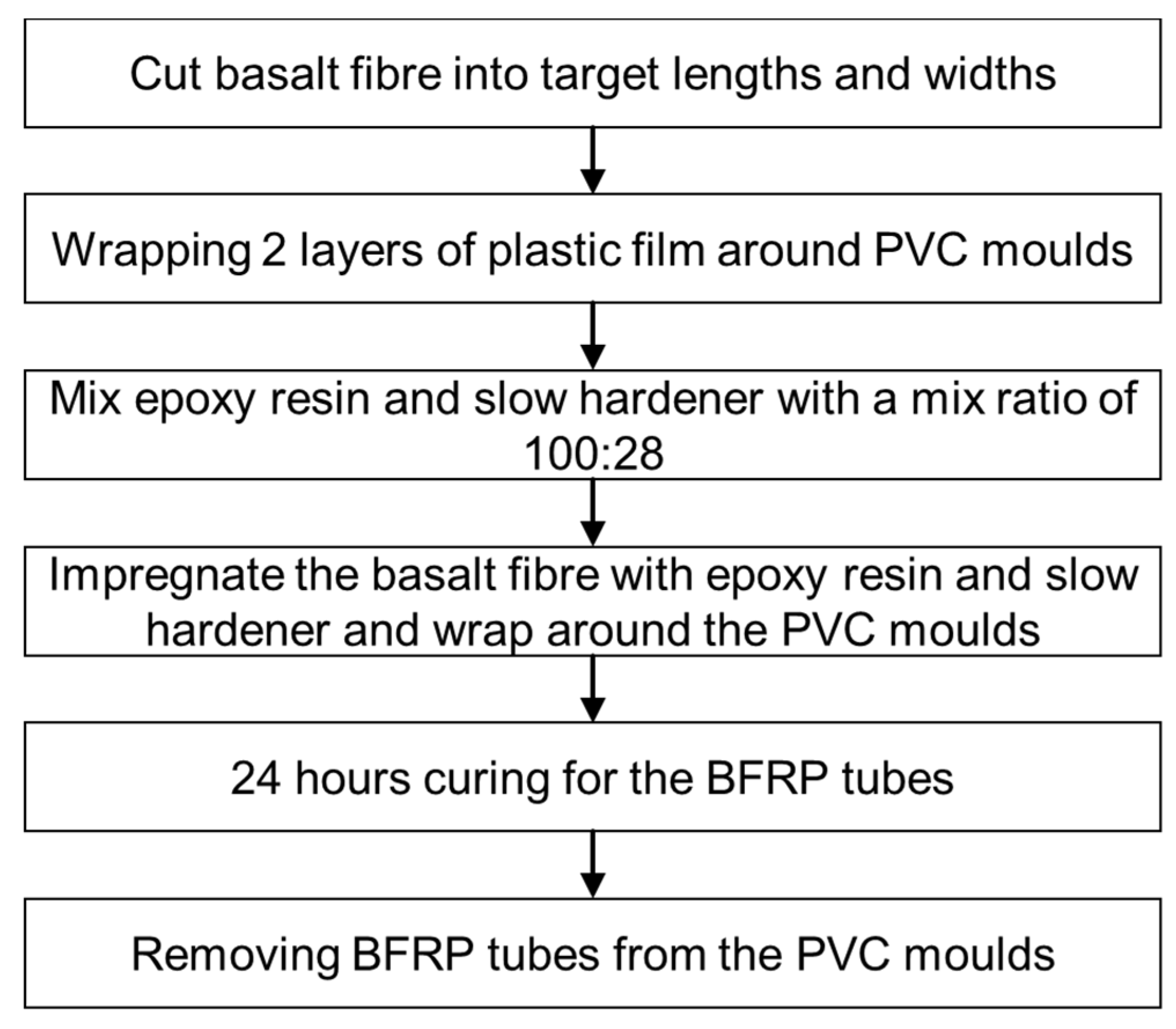
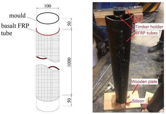
Two BFRP tubes were manufactured using the hand lay-up process (see Figure 2). The outer BFRP and FFRP tubes were approximately 100 mm in diameter, and the inner tubes were approximately 25 mm. Both the inner and outer tubes of the BFRP tubes comprise 12 layers. The fibre was first cut into the target size and was impregnated with epoxy for 30 min. The epoxy was the same as that of manufacturing coupons. A mould was wrapped in plastic film and brushed with Epoxy primer/oil for the ease of demoulding. The basalt fibre was then wrapped around the mould and cured for 24 h at room temperature. While wrapping the BFRP on the mould, a 20 mm buffer was left on each end. After removing the basalt fibre tube from the mould, the buffer parts were cut to create a flat surface.
Figure 2.
Manufacturing process of BFRP tubes.
For the manufacturing of CFRC, cement, water, gravel, sand and coconut fibre were mixed by weight in a ratio of 1:0.58:3.72:2.37:0.005, respectively. Coconut fibres were cut to a length of 50 mm and were added to the concrete during mixing. The maximum size of gravel was around 13 mm, and the sand used with a fineness modulus of 2.75. The resultant compressive strength of CFRC is 32.1 MPa.
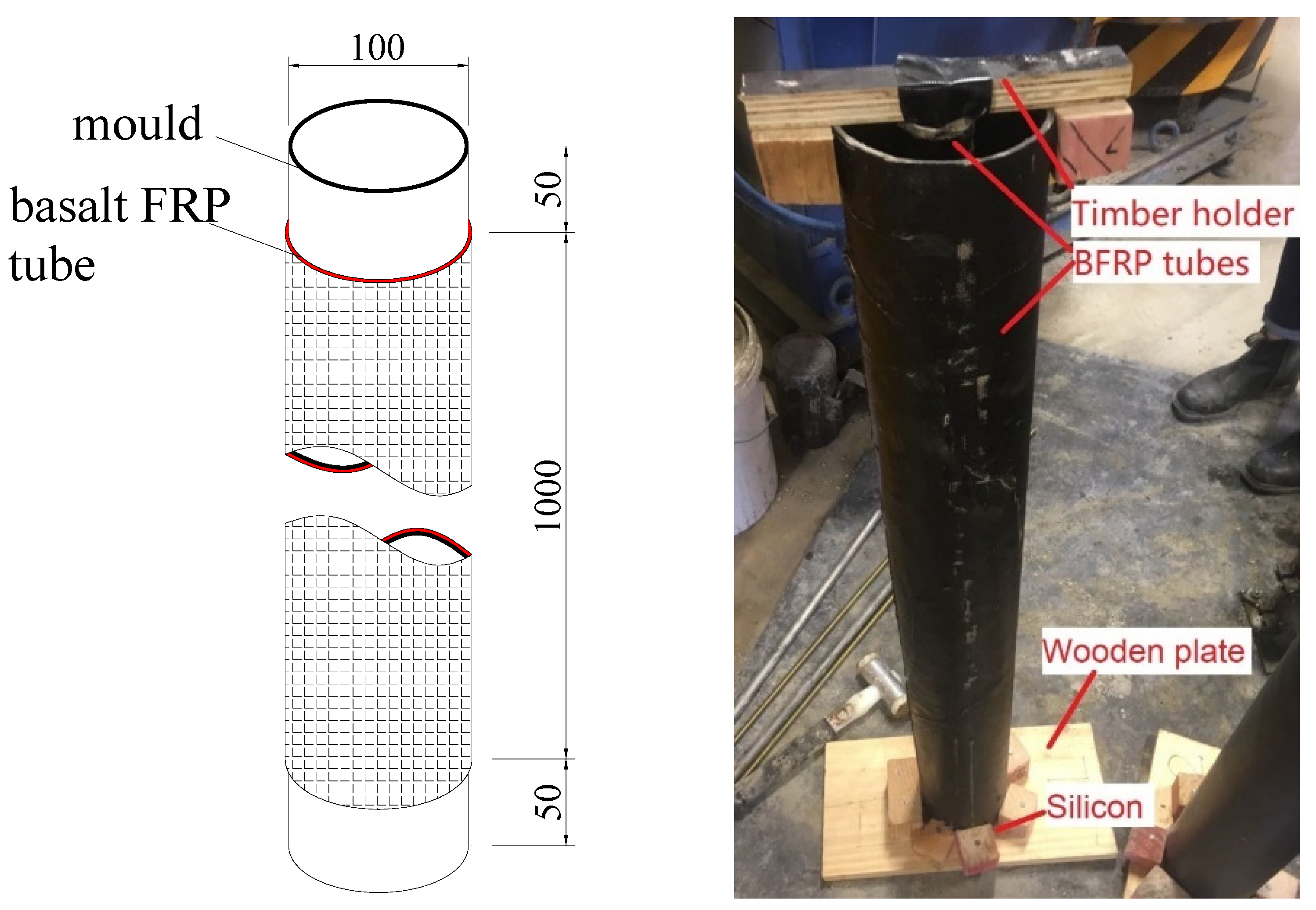
Before concrete pouring, one end of the BFRP tube is sealed with silicon on a wooden plate. For specimens with an inner tube, the inner tube was sealed on the plate similarly to the outer tubes. Additionally, a timber holder was placed at the top of the specimen (see Figure 3) to hold the inner tube in place during concrete pouring. Concrete was subsequently cast, poured, compacted and cured in a standard curing room for 28 days. A total of 2 specimens with a height of 1000 mm were made. Table 1 shows the specimen configuration. The configuration of the DFFRP confined CFRC columns is the same as the DBFRP-CFRC, i.e., dimensions and thicknesses of the tubes. Both the inner and the outer tubes of DFFRP are 4 layers.
Figure 3.
Preparation of BFRP tubes for concrete pouring.
Table 1.
Configurations for compressive test.
2.2. Instrumentation and Test Set-Up
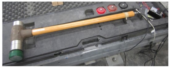
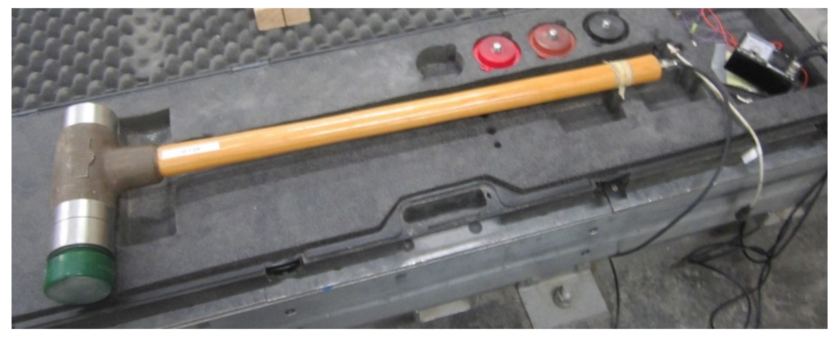
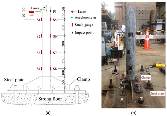
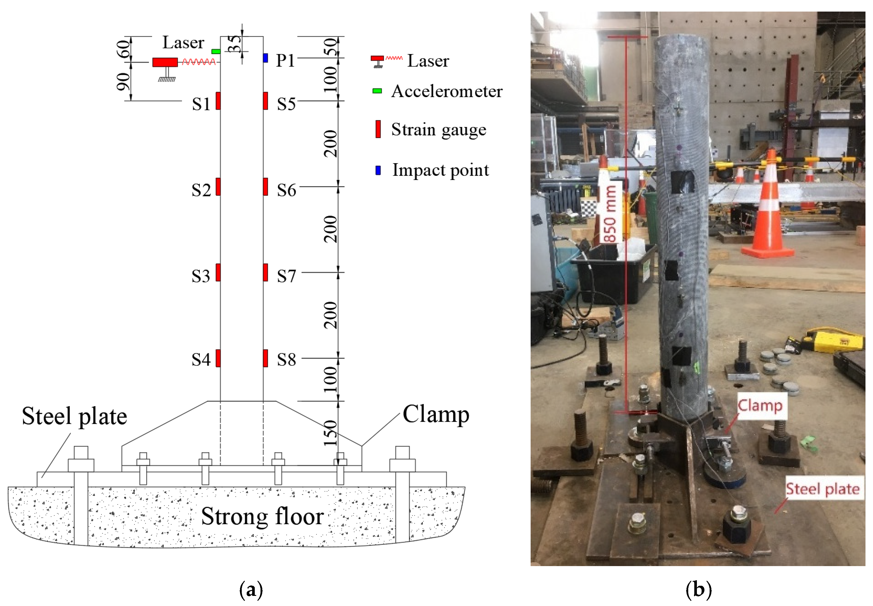
The 1 m long specimen was fixed at one end using a steel clamp on a steel plate. The steel plate was fixed on the strong floor. The specimen was struck 60 mm below the top by a calibrated impulse hammer. Different impact loads were generated by a verified impulse hammer, Dytran model 5803A (see Figure 4). The hammer is an IEPE impulse sledgehammer, used to excite larger structures with a definable impulse force, for purposes of studying their dynamic behaviour. The hammer has a head weight of 5.44 kg with a sensitivity of 0.25 mV/N and an available measurement range of 22.2 kN. Electrical connection is achieved via a BNC jack located at the end of the hammer handle. The impulse sledgehammer incorporates a special acceleration-compensated piezoelectric force sensor in the hammer head at the striking face, ensuring a smooth frequency spectrum that is free from anomalies. The instrumentations are shown in Figure 5a. The test setup is shown in Figure 5b. Four strain gauges were placed longitudinally, on both sides, and were distributed evenly along the longitudinal axis of the specimen. An accelerometer was placed 35 mm below the top of the specimen to measure the acceleration during and after impact. A laser was located 60 mm from the top to measure the lateral displacement. The resulting impact load, acceleration, displacement and strains were recorded using a data logger with a sampling rate of 2000 Hz.
Figure 4.
Impulse hammer device.
Figure 5.
Flexural test setup: (a) instrumentation and (b) physical setup.
3. Results and Discussion
3.1. Effective Mass and Base Shear
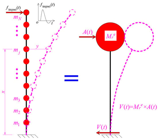
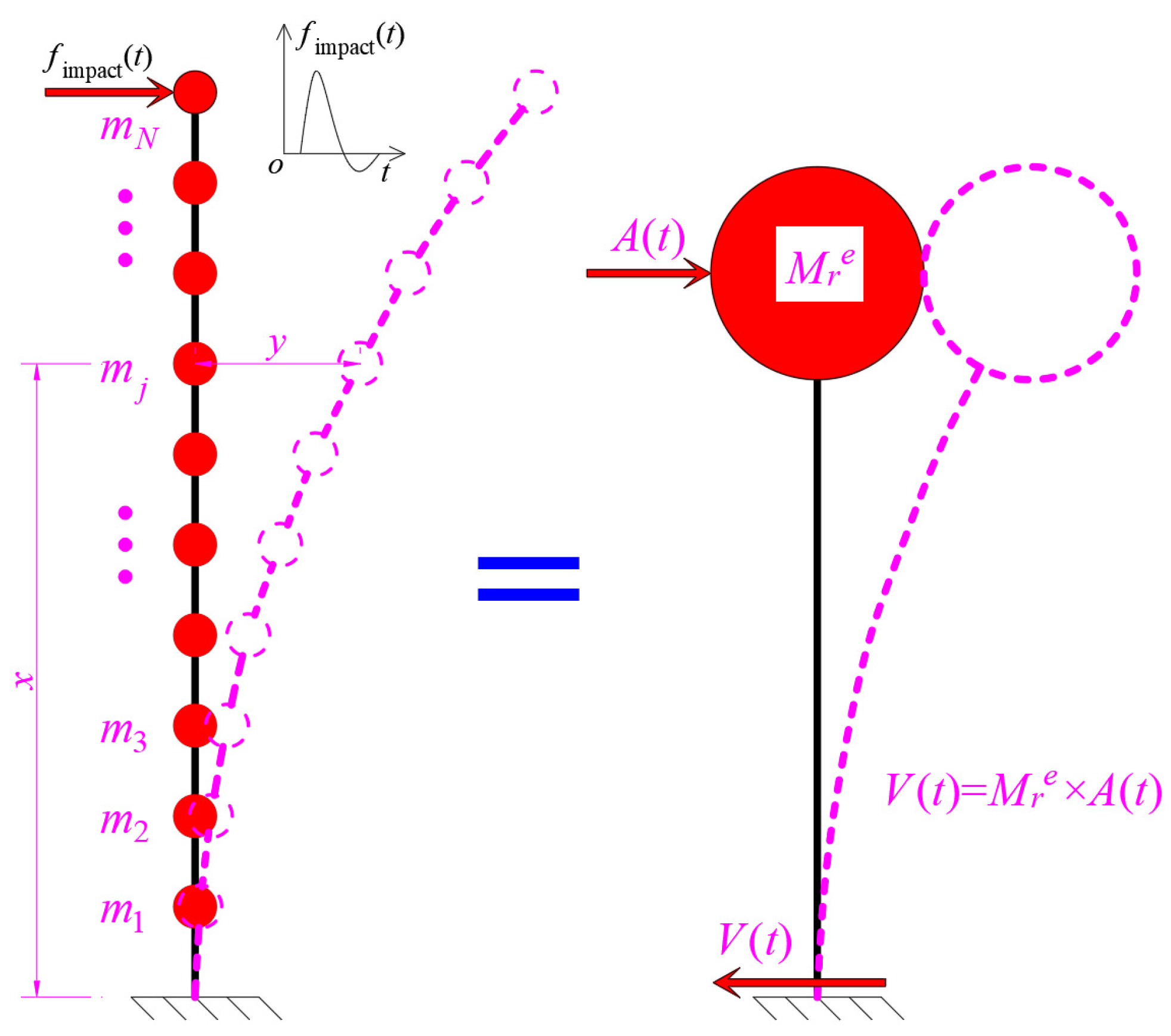
The core objective of this theoretical model is to quantify the load-transferring behaviour of the cantilever column specimens by establishing a direct correlation between the measured dynamic response and the key mechanical indicator reflecting load transmission. The shear at the base of the specimen was calculated and compared to the impact load. To simplify the mechanical analysis of the continuous cantilever column, the specimen is evenly divided into N discrete portions with equal mass. This step converts the continuous elastic body into a lumped-mass model (see Figure 6). The discretization serves two critical purposes: first, it transforms the complex distributed mass and stiffness of the column into a set of discrete mass points and connecting elements, which is compatible with matrix-based modal analysis; second, it ensures uniform mass distribution across the column height, eliminating the influence of uneven mass allocation on subsequent deflection and modal calculations, thus improving the consistency of theoretical results.
Figure 6.
Effective mass calculation.
The deflection along the height of the column under uniform lateral loading w can be estimated using Equation (1):
where w is the weight distributed along the specimen, x is the distance along the specimen from the base, E is the elastic modulus of the specimen, I is the second moment of inertia of the specimen and l is the length that is considered (l = 850 mm). By using Equation (1), the model assumes that the specimen’s deflection is solely driven by gravity, ignoring other minor loads that have negligible impact on the primary deformation mode; the second assumption is that the model specifies that the deflection behaviour is governed exclusively by the first vibration mode, since in structural dynamics, the first mode contribute the most to the overall deformation and dynamic response of cantilever structures, while higher-order modes have minimal influence and can be safely neglected. This assumption drastically reduces computational complexity without compromising engineering accuracy.
The calculated displacement y is then normalized with a maximum value of 1 at the tip of the specimen to standardize the mode shape scale, ensuring that the modal shape values are dimensionless and comparable across different positions of the specimen.
Effective mass is a key parameter in structural dynamics that quantifies the equivalent mass participating in vibration for a specific mode. Unlike the total physical mass of the specimen, effective mass reflects the actual mass contribution to the dynamic response, which is essential for accurately calculating the inertial force and thus the base shear. The effective mass of the specimen is then calculated using the following equations:
where is the transposed mode shape of the rth mode ( = ), m is the mass matrix of the specimen, i is the influence factor (taken as a vector of 1), Mr is the normalized mass which can be calculated as , mj is the mass at the jth portion and is the rth mode shape at the jth portion. The calculated effective mass for basalt- and flax-confined concrete is 14.73 kg and 15 kg, respectively, which is about two-thirds of the specimen weight. This result indicates that only about two-thirds of the specimen’s mass effectively participates in the first-mode vibration that dominates the load transfer process, while the remaining mass contributes minimally to the dynamic response. This finding directly reflects the mass participation characteristics during the load transfer from the specimen tip to the base.
Base shear is the ultimate indicator of load transfer, representing the shear force generated at the specimen base to balance the inertial force caused by the dynamic response. With the effective mass, the base shear can be calculated using the following equation:
where Ar(t) is the acceleration recorded at the top of the specimen.
3.2. Dynamic Properties
The fundamental frequency and damping ratio of all specimens are shown in Table 2. Both DBFRP-CFRC specimens have a frequency of 53 Hz, where DFFRP-A and -B specimens, respectively, have a frequency of 41.6 Hz and 40.6 Hz. This means that the specimen is stiffer when confined by basalt fibre. In terms of damping ratio, the DFFRP-CFRC specimens dissipate energy at a faster rate, as the average damping ratio (3.3%) is 1.5% higher than that of the DBFRP-CFRC specimens (1.8%). The reasons are as follows: first, flax fibre has an organic polymeric structure and exhibits high internal friction as well as energy dissipation capacity through fibre bundle slip; second, the moderate interfacial bonding between flax fibres and the matrix facilitates continuous interfacial micro-slip for energy dissipation; and finally, the favourable modulus matching between flax fibres and the matrix promotes the coordinated deformation of the composite and thereby improves the overall energy dissipation efficiency.
Table 2.
Summary of the dynamic properties.
3.3. Force–Time History Analysis
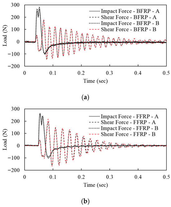
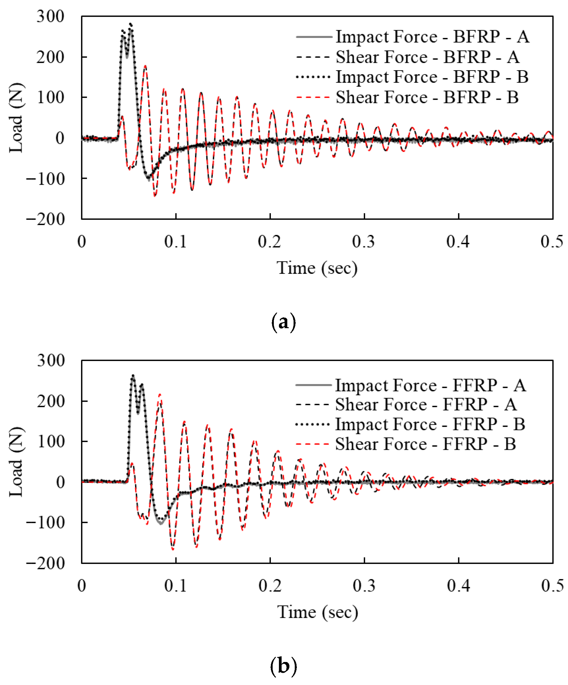
The force–time history for basalt double-reinforced concrete is shown in Figure 7a. The peak impact force is 268 N and 285 N, where the maximum shear force at the base is 180 N and 178 N for specimens A and B, respectively. The duration of the impact force is about 0.025 s. It is noted that the shear force at the base of specimens A and B is about 67% and 62% of the peak impact force, resulting in a load reduction of 33% and 38%. This indicates that some energy is dissipated as the load transfers from top to base.
Figure 7.
Force–time history for (a) DBFRP-CFRC and (b) DFFRP-CFRC.
The force–time history for flax fibre doubly reinforced concrete is shown in Figure 7b. Similarly to the specimens confined by basalt fibre, the force–time history shows a reduction in shear force at the base of the specimen. The peak impact forces are 261 N and 264 N, where the maximum shear forces at the base are 216.6 N and 194.1 N, resulting in a load reduction of 18% and 26.5% for specimens A and B, respectively.
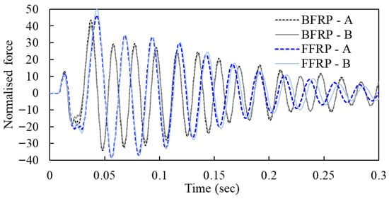
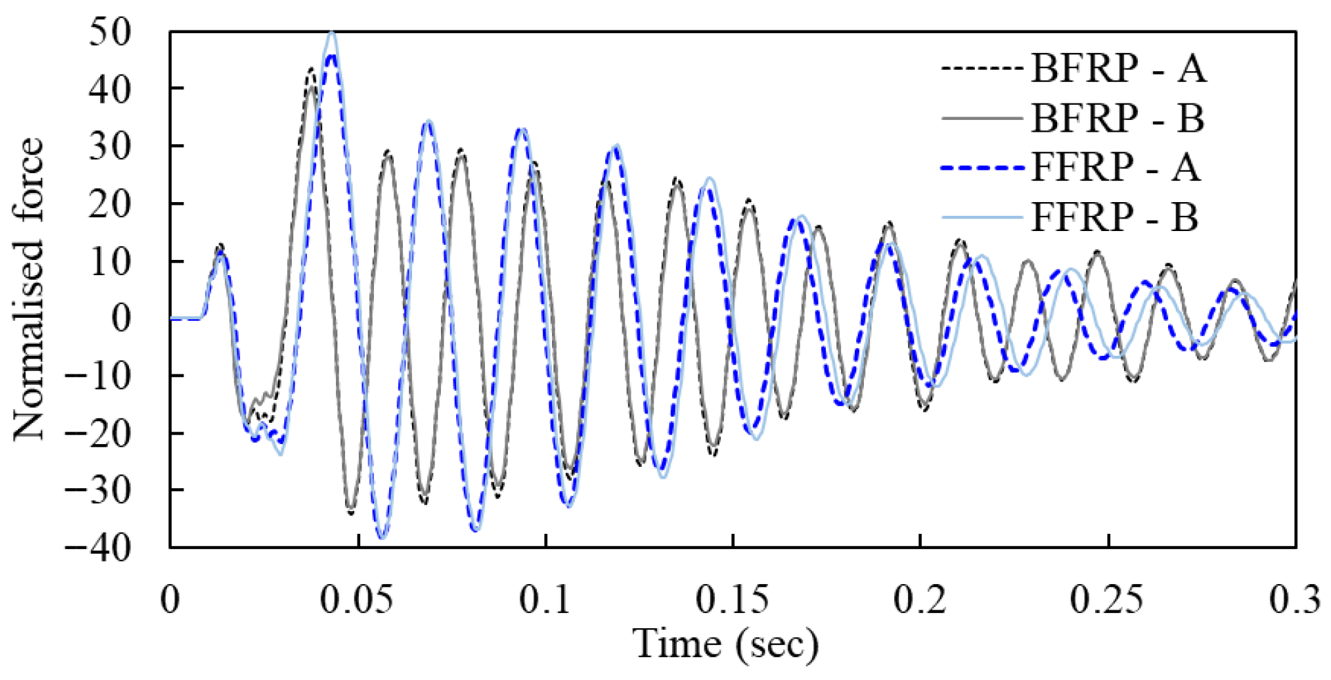
Figure 8 shows the normalized force–time history for all specimens. The calculated shear forces were normalized by the areas under the force–time history of the corresponding impacts. This is to account for the different impact loads and impact durations. The graph shows that the peak base shears of DBFRP-CFRC specimens are smaller than those of DFFRP-CFRC. It means that more energy is dissipated when force transfers from the impact point to the base of the specimen. However, it is interesting to note that DFFRP-CFRC specimens can dissipate energy faster in free vibration. The peak normalized forces for both DFFRP-CFRC specimens are higher than those of DBFRP-CFRC specimens, and become smaller at 0.15 s. This behaviour results in a higher damping ratio of DFFRP-CFRC specimens, as mentioned previously.
Figure 8.
Comparison of the normalized force–time history between DFFRP-CFRC and DBFRP-CFRC specimens.
3.4. FFT Analysis
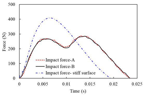
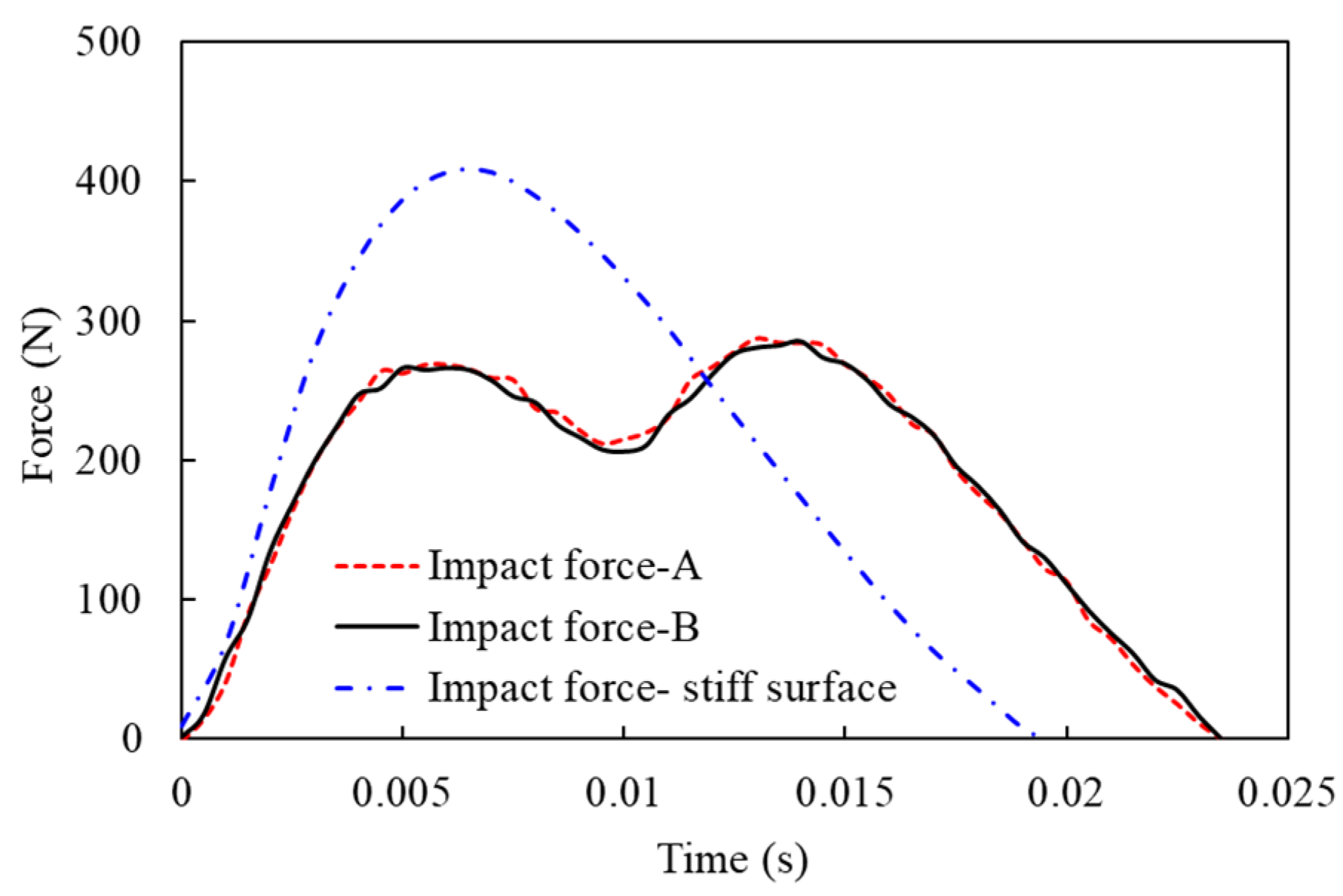
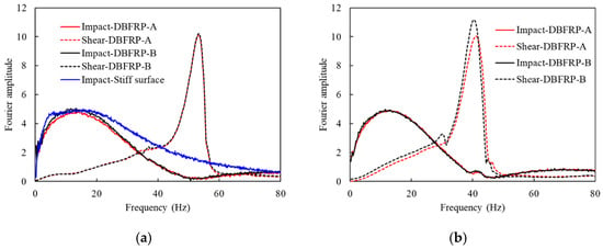
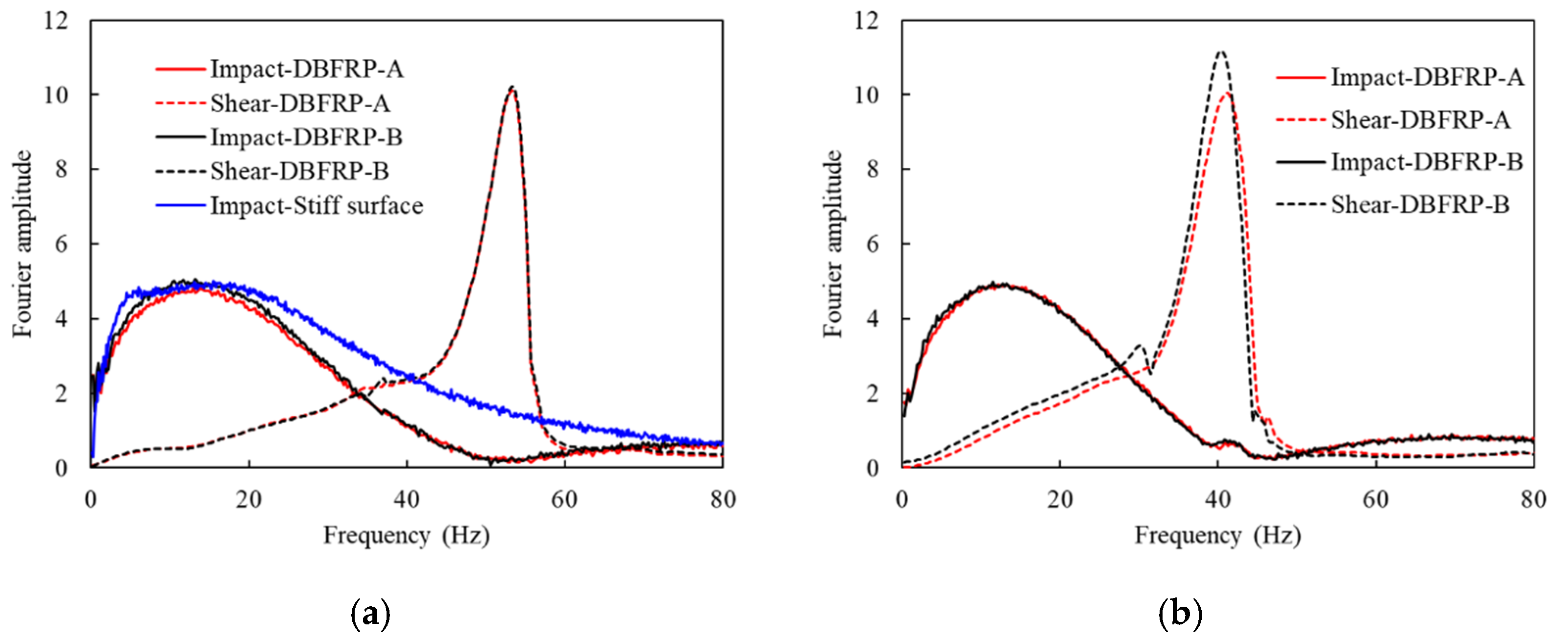
The loading process always experiences an interactive action between the loading equipment and the specimen, especially for dynamic loading. To reduce the influence of the impact strength of different impact cases, the peak impact force was normalized by the impulse of the impact on specimen A, and without changing the duration, i.e., after normalization, all three impacts had the same impulse. Figure 9 shows the normalized force–time histories produced by the hammer impacting three different surfaces. The impact force on a stiffer surface has a higher peak and shorter duration. Fast Fourier Transform was then conducted on both the impact forces and the base shear (see Figure 10). The FFT result of the impact force on the stiff surface is also displayed in Figure 10a. In comparison to the impacts on specimens A and B, the impact force on the stiff surface contains more frequencies, which means some energy has already dissipated during the loading process.
Figure 9.
Time history of normalized impact force on different surfaces.
Figure 10.
FFT results of the impact force and base shear of (a) DBFRP and (b) DFFRP columns.
Figure 10 shows that DBFRP and DFFRP columns have similar FFT results, except that DBFRP has a higher fundamental frequency. The frequencies of the impact force at the tip range from 0 to 50 Hz. After transferring to the base, the domain frequency shifts to the fundamental frequency of the column, around 53 Hz and 41 Hz, respectively, for the DBFRP and DFFRP columns. The area under the curve for the impact force and shear force of DBFRP-A is 171.70 and 144.13, respectively. This area can be used to represent the energy input and output of the column. That means about 16.06% of the energy was dissipated during the impact load transferring from the tip to the base. The corresponding energy dissipations of DBFRP-B, DFFRP-A, and DFFRP-B are 18.72%, 13.08% and 7.83%, respectively. The energy dissipation characteristics are summarized in Table 3.
Table 3.
Energy dissipation characteristics.
4. Conclusions
Coconut fibre-reinforced concrete confined with double basalt and flax fibre reinforced polymer tubes were studied in this work (termed as DBFRP-CFRC and DFFRP-CFRC, respectively). One end of the column was fixed on a strong floor, and an impact force was stroke at the top using an impact hammer. The dynamic behaviour, i.e., base shear, frequency and damping, was investigated and compared. Based on the test results, the following conclusions can be drawn:
- (1)
- The impact force applied at the top of the cantilever column, after transferring to the base, is reduced to about 33% and 38% for DBFRP columns and 18% and 26.5% for DFFRP columns, respectively.
- (2)
- The BFRP columns have higher stiffness and lower damping ratios in comparison to FFRP.
- (3)
- The normalized shear at the base of DFFRP-CFRC specimens is higher than that of DBFRP-CFRC columns, while DFFRP-CFRC dissipates energy faster in free vibration.
- (4)
- The energy dissipation obtained from FFT analysis of DBFRP-A and -B is, respectively, 16.06% and 18.72%, while that of DFFRP-A and -B is 13.08% and 7.83%, respectively.
It should be noted that the conclusions are derived solely from scaled specimens; thus, additional research is required for full-scale structural applications.
Author Contributions
Conceptualization, Y.L.; Methodology, B.Z. and Y.L.; Validation, B.Z.; Formal analysis, B.Z.; Writing—original draft, B.Z.; Writing—review and editing, Y.L.; Supervision, Y.L.; Funding acquisition, Y.L. All authors have read and agreed to the published version of the manuscript.
Funding
This research was funded by the open fund of the Key Laboratory of Fire Protection and Retardant Technology, Ministry of Emergency Management under grant number FHZR2023KFZD_04, and the Tianjin Nature Science Foundation (Grant No. 24JCYBJC00100).
Data Availability Statement
The original contributions presented in this study are included in the article. Further inquiries can be directed to the corresponding author.
Acknowledgments
The authors would like to thank colleagues at the University of Auckland, New Zealand, for the support in the tests.
Conflicts of Interest
The authors declare no conflicts of interest.
References
- Bakis, C.E.; Bank, L.C.; Brown, V.; Cosenza, E.; Davalos, J.F.; Lesko, J.J.; Machida, A.; Rizkalla, S.H.; Triantafillou, T.C. Fiber-reinforced polymer composites for construction—State-of-the-art review. J. Compos. Constr. 2002, 6, 73–87. [Google Scholar] [CrossRef] [Scilit]
- Ramakrishna, G.; Sundararajan, T. Impact strength of a few natural fibre reinforced cement mortar slabs: A comparative study. Cem. Concr. Compos. 2005, 27, 547–553. [Google Scholar] [CrossRef] [Scilit]
- Ali, M.; Chouw, N. Experimental investigations on coconut-fibre rope tensile strength and pullout from coconut fibre reinforced concrete. Constr. Build. Mater. 2013, 41, 681–690. [Google Scholar] [CrossRef] [Scilit]
- Ali, M.; Li, X.; Chouw, N. Experimental investigations on bond strength between coconut fibre and concrete. Mater. Des. 2013, 44, 596–605. [Google Scholar] [CrossRef] [Scilit]
- Ali, M.; Liu, A.; Sou, H.; Chouw, N. Mechanical and dynamic properties of coconut fibre reinforced concrete. Constr. Build. Mater. 2012, 30, 814–825. [Google Scholar] [CrossRef] [Scilit]
- Wang, W.; Chouw, N. The behaviour of coconut fibre reinforced concrete (CFRC) under impact loading. Constr. Build. Mater. 2017, 134, 452–461. [Google Scholar] [CrossRef] [Scilit]
- Islam, S.M.; Hussain, R.R.; Morshed, M.A.Z. Fibre-reinforced concrete incorporating locally available natural fibres in normal- and high-strength concrete and a performance analysis with steel fibre- reinforced composite concrete. J. Compos. Mater. 2012, 46, 111–122. [Google Scholar] [CrossRef] [Scilit]
- Tang, Z.; Ali, M.; Chouw, N. Residual compressive and shear strengths of novel coconut- fibre-reinforced-concrete interlocking blocks. Constr. Build. Mater. 2014, 66, 533–540. [Google Scholar] [CrossRef] [Scilit]
- Yan, L.; Chouw, N. Compressive and flexural behaviour and theoretical analysis of flax fibre reinforced polymer tube encased coir fibre reinforced concrete composite. Mater. Des. 2013, 52, 801–811. [Google Scholar] [CrossRef] [Scilit]
- Yan, L.; Chouw, N. Behavior and analytical modeling of natural flax fibre-reinforced polymer tube confined plain concrete and coir fibre-reinforced concrete. J. Compos. Mater. 2013, 47, 2133–2148. [Google Scholar] [CrossRef] [Scilit]
- Yan, L.; Chouw, N. A comparative study of steel reinforced concrete and flax fibre reinforced polymer tube confined coconut fibre reinforced concrete beams. J. Reinf. Plast. Compos. 2013, 32, 1155–1164. [Google Scholar] [CrossRef] [Scilit]
- Yan, L.; Chouw, N. Dynamic and static properties of flax fibre reinforced polymer tube confined coir fibre reinforced concrete. J. Compos. Mater. 2014, 48, 1595–1610. [Google Scholar] [CrossRef] [Scilit]
- Long, Y.L.; Zhu, J. Experimental study on concrete columns with various sizes confined by BFRP and hybrid FRP under axial compression. Adv. Mater. Res. 2014, 838, 407–411. [Google Scholar] [CrossRef] [Scilit]
- Campione, G.; La Mendola, L.; Monaco, A.; Valenza, A.; Fiore, V. Behavior in compression of concrete cylinders externally wrapped with basalt fibers. Compos. Part B Eng. 2015, 69, 576–586. [Google Scholar] [CrossRef] [Scilit]
- Sadeghian, P.; Fillmore, B. Strain distribution of basalt FRP-wrapped concrete cylinders. Case Stud. Constr. Mater. 2018, 9, e00171. [Google Scholar] [CrossRef] [Scilit]
- Wei, Y.; Zhang, X.; Wu, G.; Zhou, Y. Behaviour of concrete confined by both steel spirals and fiber-reinforced polymer under axial load. Compos. Struct. 2018, 192, 577–591. [Google Scholar] [CrossRef] [Scilit]
- Liu, H.X.; Liu, G.J.; Wang, X.Z.; Kong, X.Q. Effect of cross-sectional aspect ratio and basalt fiber-reinforced polymer-confined number on axial compression behavior of short columns. J. Reinf. Plast. Compos. 2015, 34, 782–794. [Google Scholar] [CrossRef] [Scilit]
- Lv, Y.; Wu, X.; Zhu, Y.; Liang, X.; Cheng, Q.; Gao, M. Compression Behavior of Basalt Fiber-Reinforced Polymer Tube-Confined Coconut Fiber-Reinforced Concrete. Adv. Mater. Sci. Eng. 2018, 2018, 7982396. [Google Scholar] [CrossRef] [Scilit]
- Lv, Y.; Wu, X.; Gao, M.; Chen, J.; Zhu, Y.; Cheng, Q.; Chen, Y. Flexural Behavior of Basalt Fiber Reinforced Polymer Tube Confined Coconut Fiber Reinforced Concrete. Adv. Mater. Sci. Eng. 2019, 2019, 1670478. [Google Scholar] [CrossRef] [Scilit]
- Chen, W.; Pham, T.M.; Sichembe, H.; Chen, L.; Hao, H. Experimental study of flexural behaviour of RC beams strengthened by longitudinal and U-shaped basalt FRP sheet. Compos. Part B Eng. 2018, 134, 114–126. [Google Scholar] [CrossRef] [Scilit]
- Gribniak, V.; Arnautov, A.K.; Kaklauskas, G.; Tamulenas, V.; Timinskas, E.; Sokolov, A. Investigation on application of basalt materials as reinforcement for flexural elements of concrete bridges. Balt. J. Road Bridge Eng. 2015, 10, 201–206. [Google Scholar] [CrossRef] [Scilit]
- Wang, W.; Chouw, N. Experimental and theoretical studies of flax FRP strengthened coconut fibre reinforced concrete slabs under impact loadings. Constr. Build. Mater. 2018, 171, 546–557. [Google Scholar] [CrossRef] [Scilit]
- Chen, J.; Chouw, N. Compressive behaviour of flax FRP double tube confined coconut fibre reinforced concrete. Constr. Build. Mater. 2016, 112, 666–673. [Google Scholar] [CrossRef] [Scilit]
- Wu, G.; Gu, D.; Jiang, J. Comparative study on seismic performance of circular concrete columns strengthened with BFRP and CFRP composites. Ind. Constr. 2007, 37, 19–23. [Google Scholar]
- Zhou, Y.Y.; Yu, J.T.; Lu, Z.D.; Zhang, K.C. Seismic behavior of BFRP-reinforced pre-damaged concrete beam-column joints. J. Cent. South Univ. (Sci. Technol.) 2010, 41, 1514–1521. [Google Scholar]
- Ouyang, L.J.; Gao, W.Y.; Zhen, B.; Lu, Z.D. Seismic retrofit of square reinforced concrete columns using basalt and carbon fiber-reinforced polymer sheets: A comparative study. Compos. Struct. 2017, 162, 294–307. [Google Scholar] [CrossRef] [Scilit]
- Zhao, D.B.; Yi, W.J.; Kunnath, S.K. Shear mechanisms in reinforced concrete beams under impact loading. J. Struct. Eng. 2017, 143, 04017089. [Google Scholar] [CrossRef] [Scilit]
- ASTM C78-10; Standard Test Method for Flexural Strength of Concrete. ASTM Standard: West Conshohocken, PA, USA, 2010.

Disclaimer/Publisher’s Note: The statements, opinions and data contained in all publications are solely those of the individual author(s) and contributor(s) and not of MDPI and/or the editor(s). MDPI and/or the editor(s) disclaim responsibility for any injury to people or property resulting from any ideas, methods, instructions or products referred to in the content. |
© 2026 by the authors. Licensee MDPI, Basel, Switzerland. This article is an open access article distributed under the terms and conditions of the Creative Commons Attribution (CC BY) license.