


Abstract
The main difficulty of pitch diameter calculation arises during the determination of the coordinates of the probing element and screw surface contact. This paper proposes a mathematical model for pitch diameter calculation of thread gauges using a two-ball stylus for internal thread calibration and three wires for external thread calibration. To describe the geometry of the thread and probing element, a non-linear equation system has been established and solved numerically. The solution of this system gives the actual contact points of the probing element with the thread profile. Pitch diameter is calculated directly without any further corrections. This mathematical model can be applied to parallel threads without any restrictions regarding lead and flank angles. Calculation of the rake correction is therefore avoided completely. The authors provide functional PHP/HTML code that can be easily integrated into any PHP-based website. Additionally, an open-access web tool has been developed that enables the direct calculation of thread pitch diameter from measured values, as well as the coordinates of the actual contact points between the thread profile and the measuring elements.
1. Introduction
Threaded connections are a key element in technical systems and are widely used in various industrial areas due to their versatility and reliability. In mechanical engineering, they are used to transfer forces, adjust, fasten, and achieve precise mechanical motion. Construction relies on threaded elements in the assembly of structures, installations, and systems exposed to variable loads and demanding environmental conditions. In medicine and dentistry, threads play a key role in implants, orthopedic fixation systems, and dental prosthetic components. In addition to the above areas, threaded elements are widely used in the energy and transport industry, precision mechanics, etc.
Extensive research has confirmed that the geometry of the thread, including profile, angle, lead, and pitch diameter, significantly affects the mechanical behaviour of the connection, stress distribution, and long-term reliability. Studies have shown that even small deviations in geometry can lead to stress concentration, reduced durability, or joint failure, especially in systems exposed to complex mechanical and thermal loads. Study [1] investigates the effect of thread dimensional conformance on the yield and tensile strength of fasteners. Tests on bolts and nuts with both conforming and nonconforming dimensions showed that undersized pitch and major diameters or oversized pitch and minor diameters significantly reduce strength. Variations in bolt pitch diameter had the greatest impact, with conforming fasteners exhibiting significantly higher tensile strength than nonconforming ones. The influence of limit deviations in thread parameters on the sealing performance of drill pipe joints was explored in study [2]. The effects of taper, angle, and pitch deviations under torque and axial load were analyzed. Results show that pitch deviations strongly affect sealing performance, taper deviations reduce sealing under tensile load, and opposing side angle deviations cause local plastic deformation, highlighting the need for tighter control of thread tolerances to prevent sealing failure. Study [3] demonstrated that the length of the thread and the thread pitch have a significant influence on the mechanical properties of threaded connections. Meanwhile, study [4] analyzed the mechanical performance of the threaded joint under complex loading conditions, revealing that the first thread root is the critical failure point. Study [5] investigated the failure behaviours of specifically designed steel–aluminum threaded connections under impact fatigue, focusing on the effects of fundamental thread parameters, such as thread shape.
In medical applications, thread geometry directly affects the biomechanical stability of implants, force transmission, and interaction with surrounding tissue, which has been confirmed through analyses of dental and orthopedic implants. Study [6] conducted a systematic review to evaluate the biomechanical effects of thread parameters—depth, width, pitch, and angle—on implant stability. The review found that variations in these parameters significantly affect load distribution, stress concentration, and overall implant stability. These findings highlight the importance of optimizing thread geometry to ensure the long-term performance of implants. In study [7], the relationship between thread pitch, cortical bone thickness, and the primary stability of orthodontic miniscrew implants in human cadaver palates was investigated. Results showed that thread pitch has a strong negative correlation with primary stability, while cortical bone thickness is positively correlated. Primary stability tests confirmed that stability decreases as thread pitch increases, highlighting the combined influence of pitch and bone thickness on implant performance. Research in work [8] investigated the influence of implant thread geometry and pitch on primary stability in a high-density polyurethane model. Implants with wider, V-shaped threads and a round apex showed greater stability. These results highlight that thread design plays a critical role in enhancing the mechanical interaction and primary stability of implants. Study [9] investigated the influence of locking screw design, specifically core diameter and thread pitch, on the stability of locked plating in osteoporotic proximal humeral fractures. Screws with a larger core diameter and lower thread pitch were compared with conventional locking screws using an osteoporotic model. The modified screws demonstrated higher fixation strength, suggesting a reduction in fixation failure rates. Research in work [10] investigated the effects of mini-screw parameters, including length, diameter, taper, and thread dept, on stress distribution and displacement in alveolar bone. Results showed that mini-screw diameter had the greatest influence on primary stability, with smaller diameters increasing stress in both bone and screw, while other design parameters had smaller effects. The findings emphasize the importance of optimizing diameter and structural design at the bone entry site. Another investigation focused on the effect of thread shape on the mechanical stability of orthodontic miniscrews in bone. Research in work [11] showed that miniscrews with a novel thread shape demonstrated higher initial stability, particularly in thinner cortical bone, compared to those with a regular thread shape. The findings emphasize the importance of selecting an appropriate thread design to achieve sufficient primary stability based on cortical bone thickness.
The reviewed research consistently highlights that the performance, reliability, and mechanical stability of threads are strongly dependent on accurate and precise measurement of thread parameters. Consequently, thread geometry remains a subject of intensive research, with significant efforts dedicated to developing methods for the precise and reliable determination of its dimensions.
Traditional contact methods continue to be widely applied due to their long-standing industrial acceptance. Alongside these established approaches, recent research explores the use of non-contact, optical techniques for thread geometry measurement. Optical systems, vision-based measurement, and laser triangulation enable rapid and precise thread profiling without physical contact with the measured object. Recent studies have demonstrated its accuracy for measurements of thread profiles. Work [12] describes the development of an online machine vision system for the automatic measurement of external threads at the end of sucker rods. Validation against conventional measurement methods for screw thread pitch, major diameter, minor diameter, and pitch diameter demonstrated high accuracy, while the approach also provides rapid measurement times, confirming its effectiveness and suitability for real-time applications. The study [13] presents a high-precision method for measuring and compensating for geometric errors of external cylindrical threads by combining machine vision with a traceable optical micrometer. Experimental validation demonstrates that the non-contact approach efficiently quantifies critical pitch diameter runout with high accuracy. In work [14], the use of a laser triangulation sensor for non-contact measurement of aerospace thread profiles under variable conditions was investigated. Transverse scanning improved capture of thread roots and crests, while surface reflectivity and tilting angles affected measurement accuracy and visibility. The results identify the limitations of the method and suggest optimization strategies for laser-based thread metrology. Study [15] proposes a novel laser-based system for measuring the thread profile of ballscrews, integrating a triangulation laser measuring unit with a dual-axis rotary stage. The system captures the longitudinal section of the thread profile while enabling precise movement of the object. Experimental validation showed that the measurements are within tolerance, and comparison with a coordinate measuring machine confirmed the high accuracy of this non-contact technique. All these studies highlight the potential of non-contact measurement methods for enhancing industrial thread inspection and quality control.
In recent years, research efforts have been increasingly directed towards 3D gear and thread metrology. For example, in work [16], a universal 3D geometry model for helical machine elements, including gears and screw threads, was proposed, enabling precise parameterization and functional description of transverse profiles. By employing modern 3D coordinate measuring technology, the approach offers a holistic evaluation of actual geometry and form deviations. The novel method can be adapted to established 2D procedures, allowing direct comparison between the two approaches. Its results have demonstrated high stability and enable comprehensive evaluation of areal measurements without any loss of information. In addition, the work [17] demonstrates non-contact optical measurements of threaded surfaces and proposes a precise 3D geometric error modelling method for external threads. The study establishes an accurate digital twin model of the bolt, incorporating actual errors, and presents a method to evaluate non-uniform distribution errors of the threaded surface. The feasibility of these approaches was validated on high-precision lead screws, confirming their applicability for precise modelling and assessment of threaded connections.
Nevertheless, classical contact-based methods for measuring thread geometry continue to be the most widely employed. Given the extensive use of threaded components across industries such as mechanical engineering, construction, medicine, and aerospace, precise and reliable determination of their geometry is crucial, particularly as tolerances become increasingly stringent. Consequently, thread geometry remains a focus of intensive research. For example, research in paper [18] deals with different calibration methods for thread ring pitch diameter, including classical mechanical probing on a 1D-length measuring machine and a coordinate measuring machine, and compares them with a modern profile-scanning method. The study analyzes how these methods affect the uncertainty of thread ring pitch diameter measurement. While at work [19], conventional pitch diameter calibration of screw thread gauges is examined, highlighting critical factors such as the selection of measuring wires that significantly influence measurement uncertainty, and proposing practical solutions to improve calibration reliability. All the above confirms that precise measurement of thread geometry, particularly the accurate determination of pitch diameter, is essential for ensuring the functionality and reliability of threaded connections. Accurate thread metrology is therefore critical for maintaining high-quality threads across mechanical, industrial, and biomedical applications.
2. Pitch Diameter
The pitch diameter cannot be measured directly. It must be calculated from an expression that depends on the measurement method in use. The two-ball stylus technique for internal thread calibration and the three-wire technique for external thread calibration are widely used for the calibration of screw-thread gauges. Each technique uses spherical or cylindrical probing elements, so the calculation of pitch diameter requires that the coordinates of the probing element and screw surface contact are well determined.
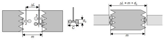
The mathematical formula given below, Equation (1) [20] applies to pitch diameter measurements using spherical or cylindrical probing elements and two or three-point measurements. The pitch diameter must be determined from the measured diameter m (defined as the distance between the centres of the probing elements touching the thread on both sides) as indicated in Figure 1, knowing the pitch P, the thread angle α, and the diameter dD of the probing elements. For a symmetrical thread with β = γ = α/2, a pitch diameter can be calculated from the expression:
where the upper sign applies to external thread (d2) and the lower sign to internal threads (D2), respectively. The term A1 is the rake correction, which considers the progressive movement of the probing elements away from the thread axis as the lead angle increases. A2 is a correction for the measurement force.
Figure 1.
Pitch diameter measurement [20].
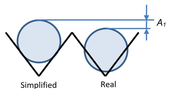
Due to the helical nature of the thread, probing elements do not contact the flanks in the axial section, and in a real representation of axial section, contact points would not be visible at all. Furthermore, probing elements would be projected as an ellipse, not as a circle. Figure 2 shows a real and simplified presentation of an axial section. The significant displacement of probing elements towards the axis of the thread can be illustrated using simplified presentation. This displacement must be corrected, and that correction is known as rake correction—A1 [21].
Figure 2.
Rake correction.
Calculation of the rake correction for symmetrical thread with small lead angle and not too steep flank angles can be made using the following approximation:
for the internal threads or:
for the external threads.
In the general case, for asymmetric, multi-start threads, the use of Berndt’s approximation theory [22,23] is generally recommended and is proposed by current EURAMET guidelines for pitch-diameter determination [20]. Although Berndt’s correction provides sufficient accuracy for many applications, it omits several geometric parameters. A comprehensive description of thread geometry, therefore, requires solving a more complex problem that accounts for these previously neglected factors. The mathematical model proposed in this work, presented in the following sections, enables accurate calculation of parallel thread pitch diameter using mechanical probing.
3. Vector-Numerical Model
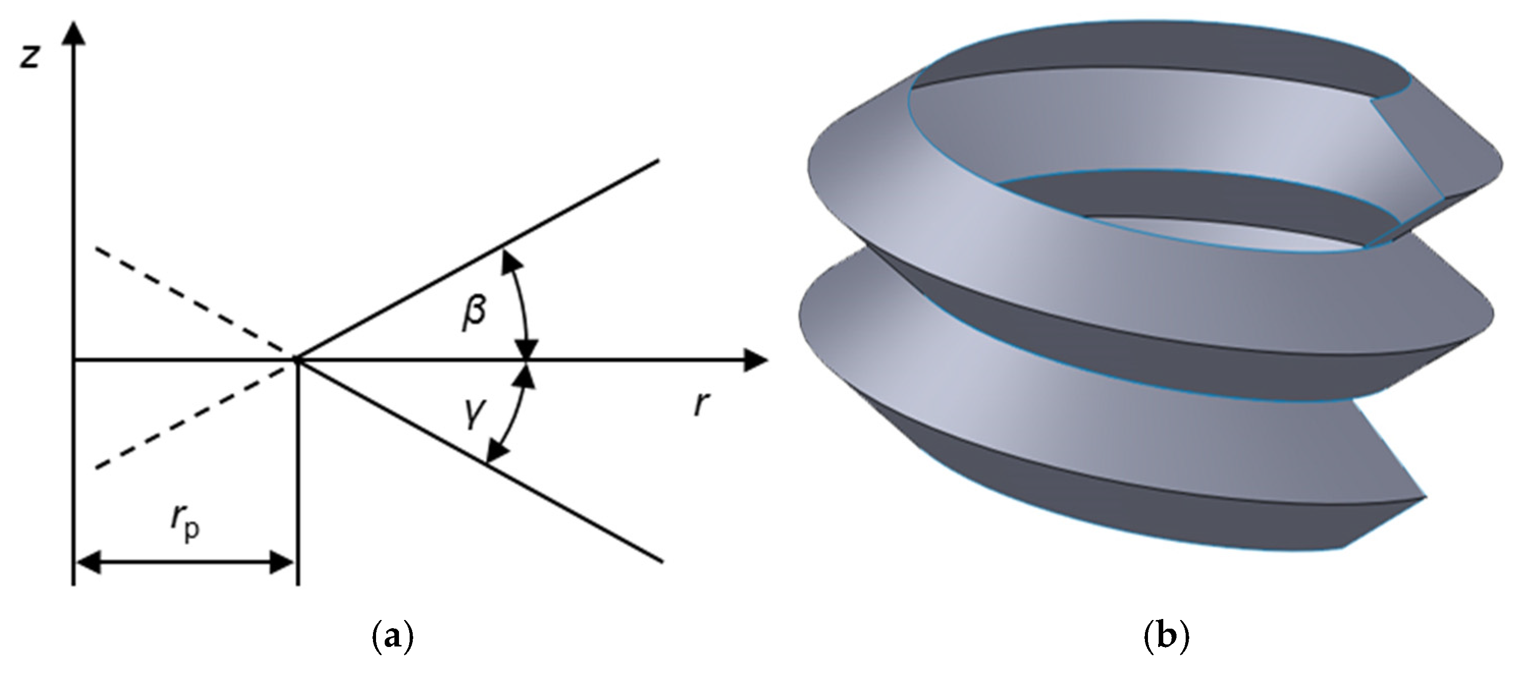
The pitch diameter calculation model described in this section is applicable for parallel, external, and internal, symmetrical and asymmetrical threads. The equation of probing element and thread geometry, along with the coordinates of probing element position (spherical or cylindrical), defines a system of nonlinear equations whose solution can be found numerically. By solving the system of equations, the coordinates of the contact point (contact between probing element and the thread profile) are obtained along with the coordinates of the centre of the probing element, from which the pitch diameter is then calculated. Every thread can be described with a characteristic helix of radius r and pitch P, and the flank angles β and γ. The mathematical model development starts with a helix equation in parametric form:
where:
and φ—lead angle, P—helix pitch, r—helix radius.
To form a helicoid that describes a flank thread surface, Equation (4) expands to:
where:
Figure 3.
The scheme thread profile: (a) Thread profile; (b) Revolved thread profile.
Two helicoids, which differ only in the flank angles, fully describe the entire geometry of the thread surfaces, so the equations of the thread can be written in the following form:
where k = 1 denotes the upper and k = 2 the lower thread flank.
Equation (7) can be written in implicit form using Cartesian coordinates:
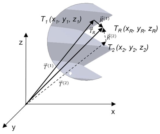
Let us now consider a probing element in contact with a thread.. If the probing element, with the centre ,, is in contact with the thread, then there are two intersection points and ,, with upper and lower thread flanks, respectively. The points , and define vectors , and shown in Figure 4. The mathematical condition for the probing element to be in contact with the thread is that the vector at the point and vector at the point are normal to the surface of the probing element and the thread surface as well. As shown in Figure 3, the norm of the vector and equals the radius of the probing element . If is vector normal to thread surface at points and can be written:
where norm vectors of are:
Vector must be coplanar with vector as well as with and by taking the fact that it can be written as:
From Equations (13) and (14) contact of thread and measuring element is described with:
If Equation (15) is expanded, two linear systems of three equations, one for measuring element contact with the lower thread flank and one with the upper thread flank, are obtained:
From the linear system showed by Equation (16) following equalities can be set:
Equation (10) and identities Equations (17)–(20) form a nonlinear system of eight equations with the eight unknowns. Each unknown can be assumed as a component of a vector
. In that way, a function vector which satisfies the condition can be formed:
Figure 4.
Vector presentation of thread flanks and probing element contact.
By solving the system of equations (Equations (21)–(28)), position vectors may be determined as well as the coordinates of contact points and , the centre of the probing element , and the diameter for a particular thread. It can be noticed that the system consists of nine nonlinear equations and nine unknowns: coordinates of the points: , , , , , , , , and radius . The system can be solved with one known (measured) quantity. Using the two-ball stylus technique for internal thread and the three-wire technique for external thread, the coordinate of the centre of the probing element can be easily found from the measured displacement m, see Figure 1:
4. Numerical Solution
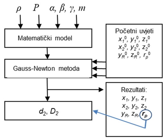
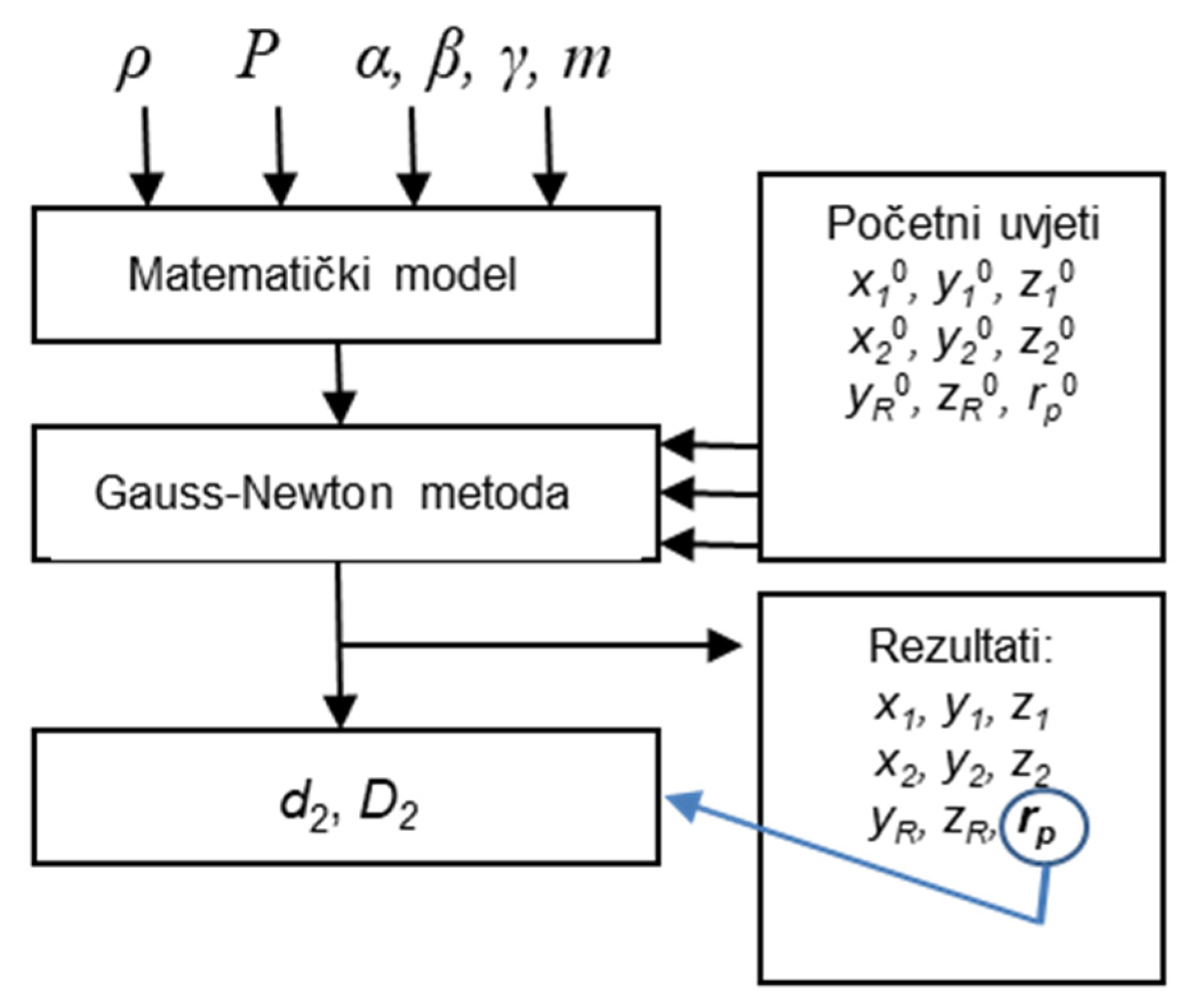
The solution of the non-linear system is presented by the block diagram given in Figure 5, showing the steps in the calculation of the pitch diameter.
Figure 5.
Block diagram for calculation of the pitch diameter.
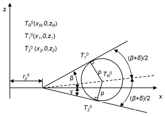
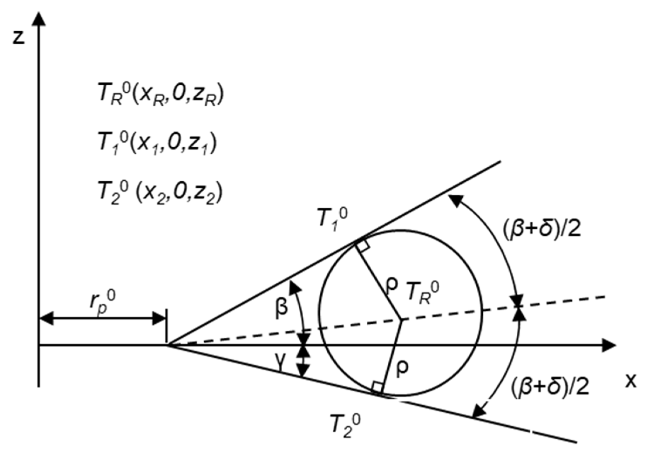
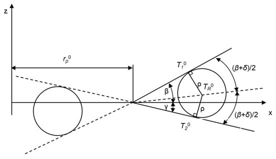
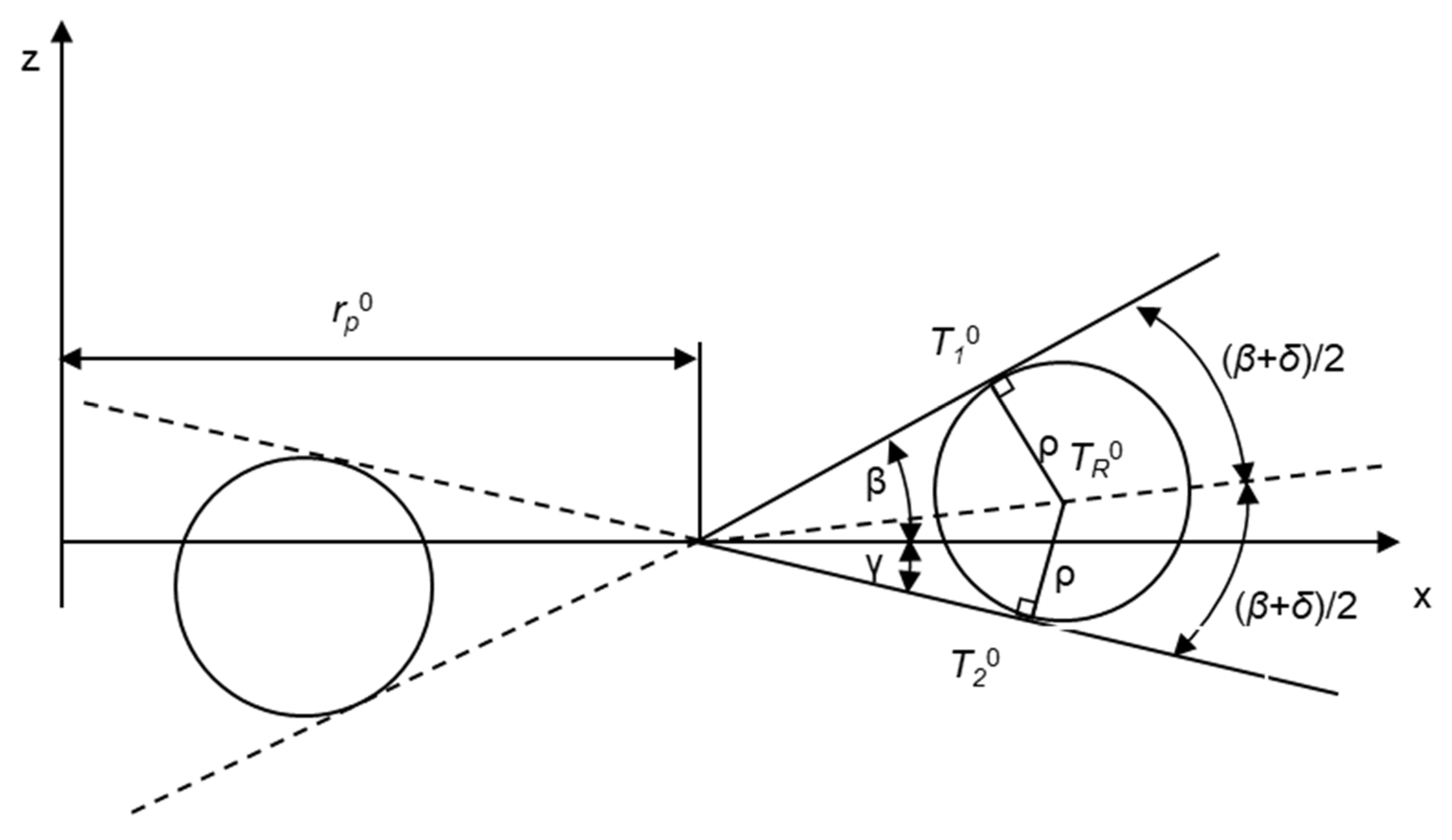
Although trust-region and Levenberg–Marquardt methods [24] generally offer faster convergence, the model presented in this work was implemented in PHP to ensure public accessibility through a web-based application. Due to its simplicity and ease of implementation, the Gauss–Newton method was therefore selected. In the proposed approach, the initial conditions are expected to be sufficiently close to the true solution when the thread is represented using a simplified geometrical model, as illustrated in Figure 6. Using Equations (32)–(40), the initial contact conditions between the ball and the thread are computed by neglecting the helical geometry of the thread. Although these conditions do not correspond to the actual contact points, the resulting solution is sufficiently close to the true one to provide reliable initial conditions for the numerical method. When such well-defined initial conditions are available, the Gauss–Newton method exhibits high robustness and consistently converges to a solution. However, if the proposed model is to be employed in iterative procedures, such as the Monte Carlo method for measurement uncertainty estimation, the use of an optimized algorithm for solving nonlinear systems of equations is strongly recommended.
Figure 6.
Definition of initial conditions.
The vector-numerical model consists of a nonlinear system of nine equations, Equations (21)–(28), where ρ, P, β, γ, and m are input parameters and results are shown by vector :
Newton’s method is defined as:
where k = 1, 2, 3…n represent the number of iteration steps, and J is the Jacobian matrix. Equation (30) can be transformed into:
where represents numerical error. The first step is the calculation of and with initial values. To define the initial conditions, i.e., the starting point of the contact and the centre of the probing element from which the iterative process begins, the model of the axial section in the y = 0 plane can be assumed as shown in Figure 6. Although this view does not correspond to the actual contact, the points , and initial conditions are certainly located close to the solution of the system.
With known coordinates of the centre of the measuring element = initials vector can be formed:
The obtained solution represents the coordinates of the contact points and the centre coordinates of the probing element R, and the radius . Equations (41) and (42) can be used for the calculation of the pitch diameter for external and internal threads respectively.
The pitch diameter of both external and internal threads is calculated in the same manner, with only slight differences in the initial conditions. When calculating the pitch diameter of an external thread, the starting point of the probing element’s centre must be larger than the radius to ensure that the system’s solution (the contact point coordinates) is found on the right side of the root. The opposite is valid when the probing element is in contact with an internal thread, see Figure 7.
Figure 7.
Contact between measuring elements with external and internal thread.
Gaussian elimination is used to solve the linear system Equation (30). From the obtained result a vector is calculated for the next iteration step.
The pitch diameter is calculated using Equation (41) or Equation (42). Iterations are made until is smaller than 10−11.
5. Online Calculator
For the development of an online calculator for determining thread pitch diameter, PHP code was created that can be easily implemented on any standard PHP server and integrated as part of a website. The source code is available in the scientific repository [25], enabling its reuse and adaptation for research or industrial applications. In addition to the code, a publicly accessible web-based calculator [26] has been developed, allowing users to directly calculate the pitch diameter based on their measured input values. The programme consists of two main scripts: index.php—main script for execution and constant.php—definitions of input constants (ρ, P, β, γ, m), initialization of the starting vector , numerical precision settings and the selection internal or external thread. Function files: fun_derivate.php, fun_function.php and fun_matrix.php contain functions for the calculation of Jacobian matrix , function for calculation of function vector and functions for matrix operations (Gaussian elimination and matrix subtraction). For HTML report of results fun_report.php can be used.
6. Verification of PHP Algorithm
The results obtained using the PHP algorithm were compared with the results obtained using the model described in the EURAMET Calibration Guide cg-10 [22] for the general case (Berndt theory-based) [26], which represents the recommended and widely applied approach for pitch diameter determination in accredited calibration laboratories and national metrology institutes. Since most calibrations are performed on symmetrical threads, the EURAMET model is considered a reference for verifying the numerical model. The verification procedure was carried out for the entire range of ISO metric threads.
To simulate measured values, an inverse function was developed in MATLAB R2020 b. Based on the values of the nominal pitch diameter d2nom and nominal pitch P according to ISO 724:2023 [27], the function calculates the theoretical measurement value m, i.e., the value that would be obtained when measuring a thread with ideal geometry and nominal pitch, flank angle, and pitch diameter. The system of nonlinear equations was solved using the optimized MATLAB function fsolve, with a tolerance of 1 × 10⁻³⁰ mm.
The measuring element diameter was determined by calculating the optimal diameter [22]. Based on this value, a diameter corresponding to a realistic measuring element was adopted, representing commercially available measuring elements used in practice, rather than an idealized nominal diameter. This approach ensures consistency with practical measurement conditions encountered when using standard measuring wires for external threads and a two-ball stylus for internal threads.
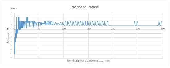
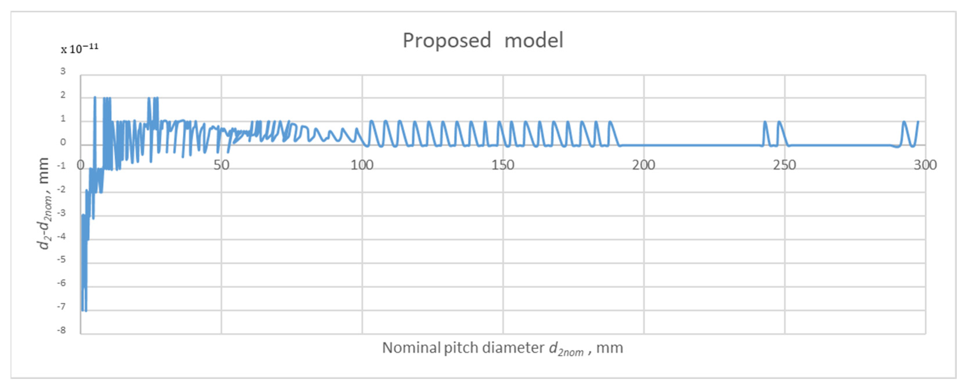
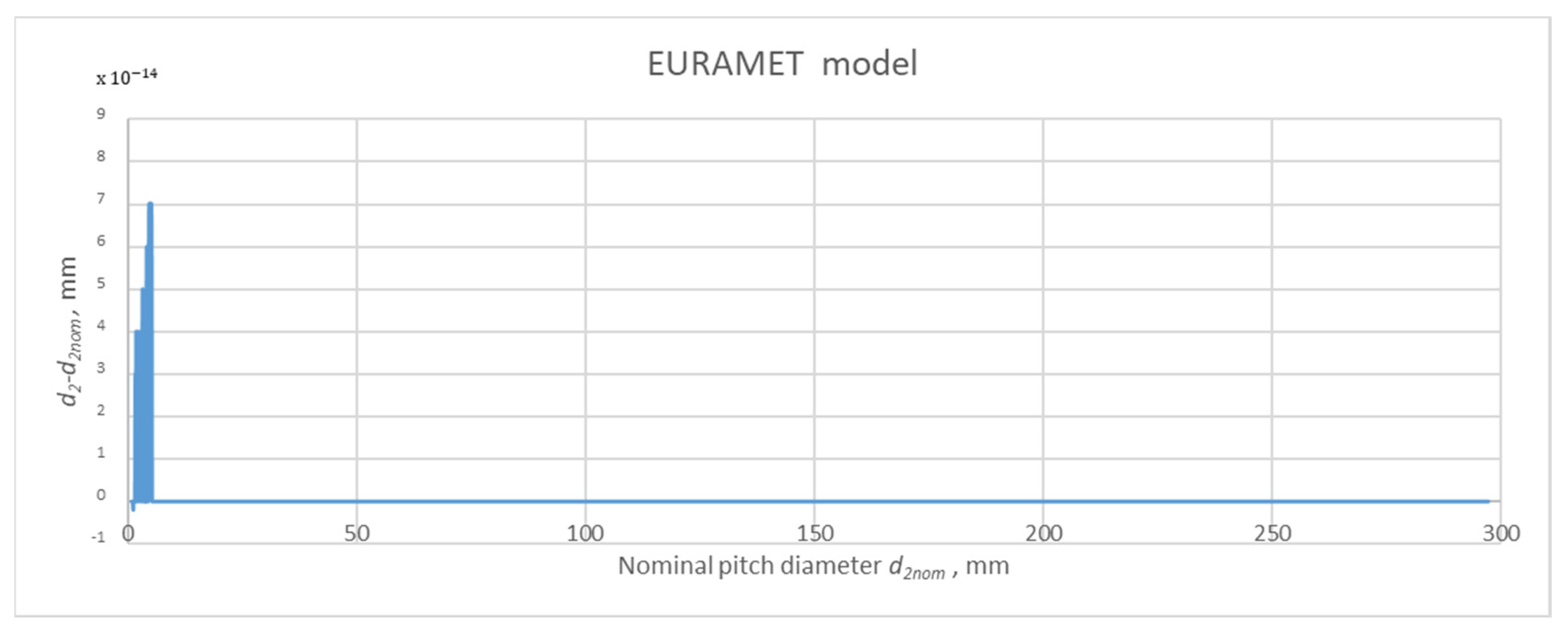
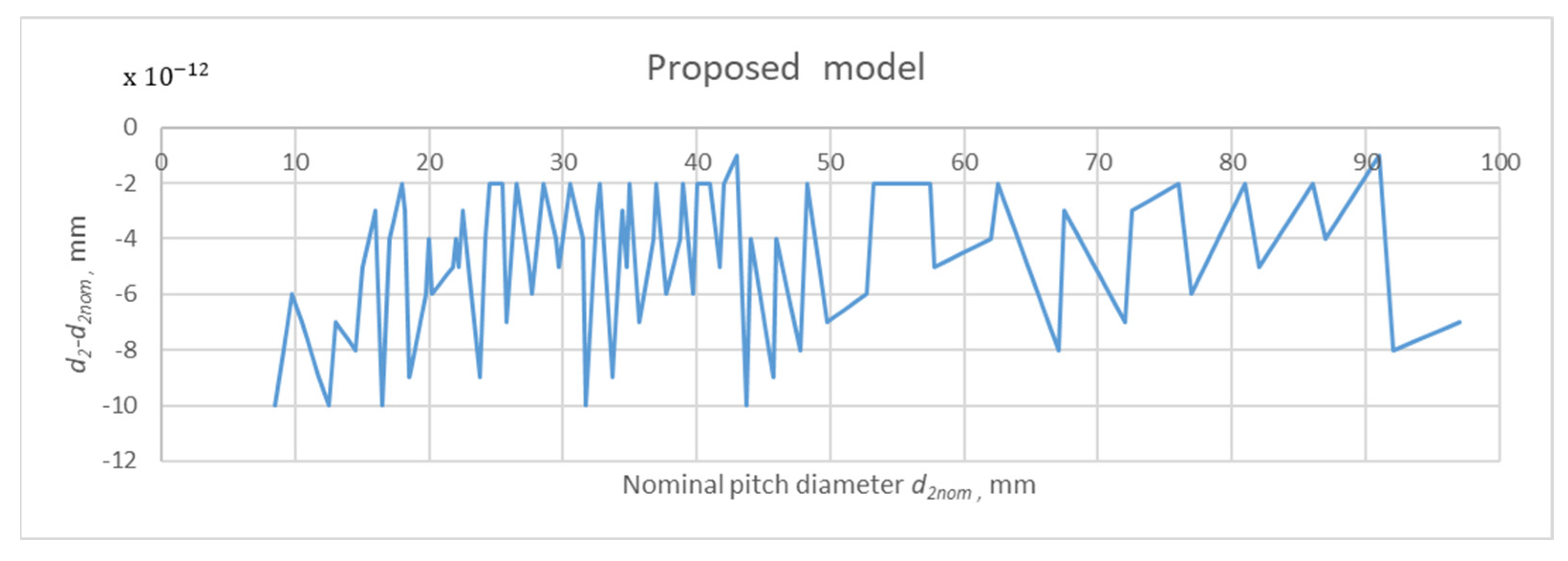
Simulations were performed for 300 external threads of different pitches and diameters, and 300 internal threads. Based on the obtained values of m, the pitch diameters were calculated using Berndt’s theory and the proposed model via the web application. The results were compared with the nominal pitch diameter values. The analysis demonstrated that both models exhibit high accuracy in the calculation of the pitch diameter of symmetrical threads. The resulting errors are presented in Figure 8 and Figure 9.
Figure 8.
PHP software: Deviation from the nominal value of pitch diameter for external M threads.
Figure 9.
EURAMET model (reference): Deviation from the nominal value of pitch diameter for external M threads.
Accordingly, the proposed model was validated in two steps. In the first step, the inverse function implemented in MATLAB used the same equations and initial conditions as those described in Section 3. The calculation based on the EURAMET guide yielded all values close to the nominal pitch diameter d2nom.
In the second step, when d2 was calculated using the web application, the PHP implementation was validated, and the maximum numerical error of the implemented Gauss–Newton method was quantified. The same simulations were performed for internal threads, with identical results in terms of error calculations, although the number of iterations differed.
Overall, for symmetrical threads, the average computing time was 0.51 s, which is acceptable for web-based applications. The average number of iterations was 25, and the maximum numerical error was 2 × 10⁻¹¹. Additional data is presented in Table 1.
Table 1.
Simulation analysis—symmetrical threads.
An additional verification was performed using the test values proposed in [22]. A summary of this comparison is presented in Table 2.
Table 2.
Results of pitch diameter calculated according to EURAMET guide and by PHP algorithm.
The results show no differences between the two models, except in the case of highly asymmetric threads with a large lead angle, where deviations of a few micrometres can be observed. To further investigate the behaviour of both models in the case of asymmetric threads, simulations were performed on DIN 513-2:2020-12 [28]. “S” threads. The proposed model natively treats all threads as asymmetric; therefore, the same procedure was applied as in the case of symmetrical threads. The resulting errors for external threads are presented in Figure 10.
Figure 10.
PHP software: Deviation from the nominal value of pitch diameter for external S threads.
Similar results were obtained for internal threads, and the results of the analysis are presented in Table 3.
Table 3.
Simulation analysis—asymmetric threads.
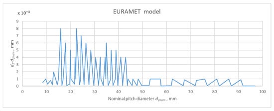
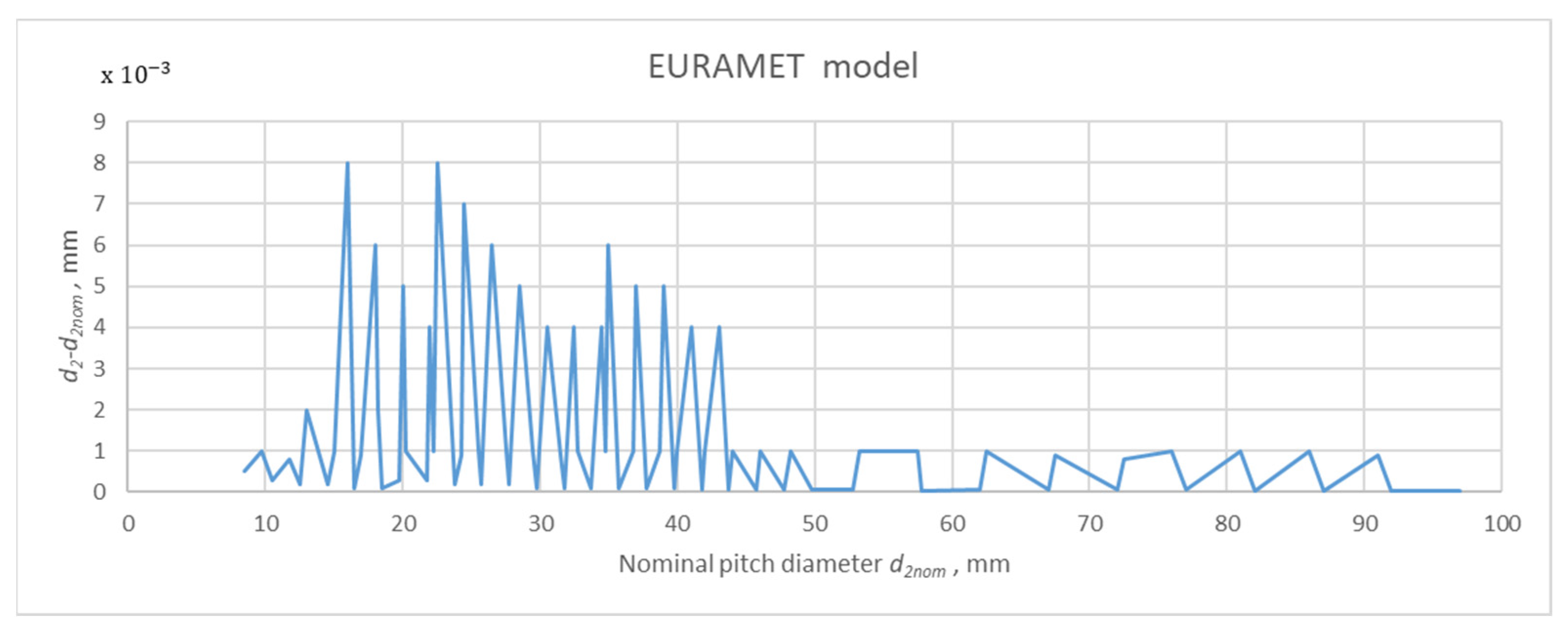
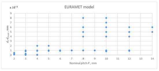
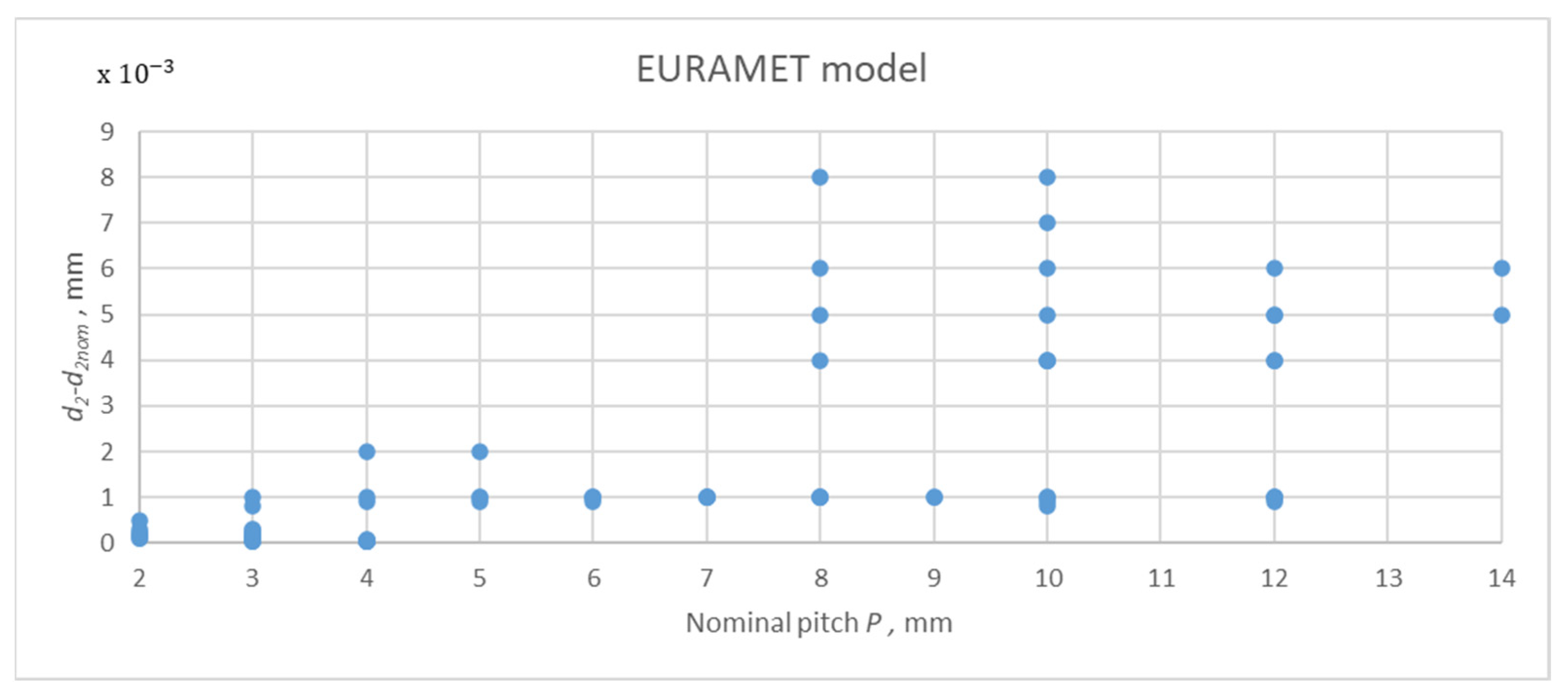
The simulation results showed that the error of the proposed PHP algorithm does not exceed 1 × 10⁻¹¹ over the entire range of S threads. However, in the case of the EURAMET model presented in Figure 11, a significant increase in deviation was observed for threads with smaller pitch diameters and larger pitch. The calculation error for different nominal thread pitches is shown in Figure 12.
Figure 11.
EURAMET model: Deviation from the nominal value of pitch diameter for external S threads.
Figure 12.
EURAMET model: Deviation from the nominal value of pitch diameter vs. pitch for external S threads.
The EURAMET model’s behaviour requires further investigation before drawing definitive scientific conclusions. However, it is not justified to use this model as a reference for asymmetric threads.
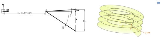
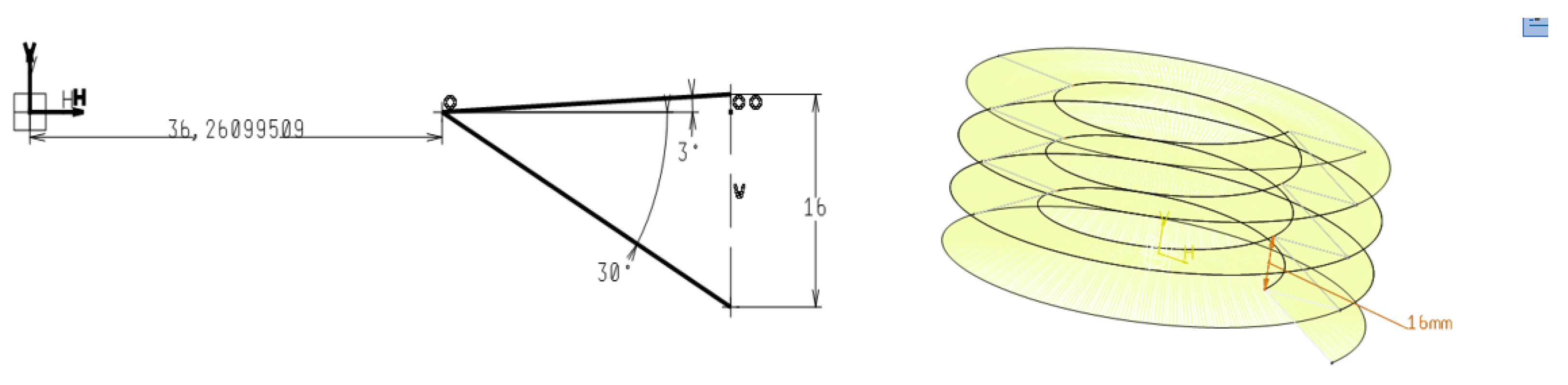
Additional verification was performed using an external thread with a nominal pitch diameter of 97.9242 mm, highlighted in Table 3, where a difference of 1.8 μm was observed. Since the proposed PHP algorithm calculates not only the pitch diameter but also the contact points, the coordinates of the measuring element centre, and the theoretical root diameter rp, both the thread geometry and its contact with the measuring element can be fully reconstructed in CAD software based on the measured value m. This approach was applied in practice using the CAD software CATIA V5R20 (Figure 13).
Figure 13.
S Thread constructed in CAD.
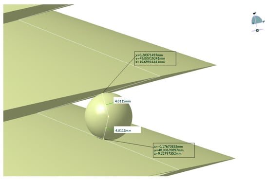
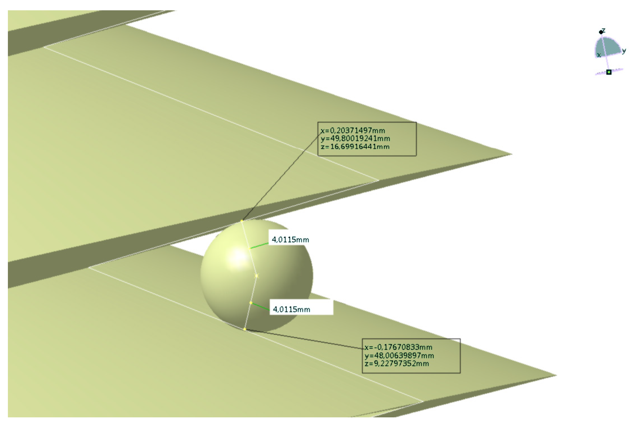
Using the coordinates of the measuring element centre calculated by the PHP algorithm, a point was constructed from which normals were extended toward the upper and lower flank surfaces of the thread. In the CAD model, the coordinates of the intersections of these normals with the thread surfaces, points T1 and T2, were then determined, as presented in Table 4 and Figure 14. Since the results agree within the numerical precision of the CAD software, the proposed PHP algorithm is considered verified for asymmetric threads as well.
Table 4.
Values calculated by the proposed PHP software and CAD model.
Figure 14.
CAD model of the contact between the measuring element and the thread surface.
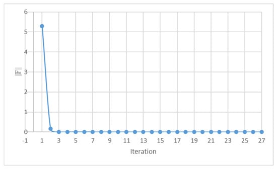
The convergence analysis of the proposed PHP algorithm was also performed for the same thread, and the results are presented in Figure 15.
Figure 15.
Convergence analysis: |F| vs. iteration number.
The proposed PHP algorithm can be considered highly robust, primarily due to the well-defined initial conditions. Its performance was evaluated on more than 600 symmetrical and 200 asymmetrical threads, and convergence was consistently achieved within a maximum of 30 iterations. No cases of incorrect results were observed.
7. Discussion of Measurement Uncertainty
The determination of the thread pitch diameter measurement uncertainty is a demanding task. For this reason, most calibration laboratories and national metrology institutes apply the methodology described in the EURAMET calibration guidelines. The guidelines recommend an uncertainty evaluation methodology that follows the principles of the GUM (Guide to the Expression of Uncertainty in Measurement) and is based on an approximate geometric model of the thread, outlined in Equations (1)–(3).
Although this approximation has certain limitations, particularly with respect to the error in the calculated pitch diameter, it is sufficiently accurate for the purpose of uncertainty estimation and can therefore be used for symmetrical threads, regardless of the mathematical model used for the pitch diameter calculation. For asymmetrical threads, the use of Monte Carlo simulations is recommended. However, due to the non-optimized Gauss–Newton algorithm and the limitations of PHP technology, the proposed model must be implemented in a more suitable computational environment, such as Python or MATLAB, to achieve faster convergence and computing time.
Measurement uncertainty depends primarily on quantities such as the measuring displacement m, the thread pitch P, the thread angle α, and the diameter of the measuring element dD. These quantities cannot be reliably determined without detailed knowledge of the applied measurement procedure, the specific instruments used, and the laboratory conditions. Consequently, each laboratory, regardless of the model used for the final calculation of the pitch diameter, is required to perform its own uncertainty evaluation in accordance with its equipment and measurement method.
The contribution of the mathematical model itself to the measurement uncertainty budget can be estimated based on the maximum error observed during simulations, in which nearly all combinations of different thread pitches, diameters, and measuring element sizes were considered. According to Table 1, the maximum observed error was 7 × 10⁻¹¹ mm. Uncertainty of calculation can be estimated assuming a rectangular distribution: .
This value is negligible even when compared with the best calibration and measurement capabilities (CMC) of national metrology institutes, which typically range from 2 µm to 5 µm for pitch diameter calibration.
8. Conclusions
In screw thread measurement, the pitch diameter cannot be measured directly; instead, it must be calculated using an expression that depends on the selected measurement method. The EURAMET Guide CG-10 recommends the model based on Berndt’s theory for determining the pitch diameter, and this approach has been widely adopted by most national metrology institutes. The Berndt model, like other calibration methods for screw-thread gauges, applies to mechanical techniques using probing elements. The main problem in pitch-diameter calculation is the accuracy of the contact-point coordinates between the probing element and the thread surface.
This paper presents an original vector-numerical model for calculating the pitch diameter from the measured value m by solving a system of nonlinear equations.
The proposed model can be used for determining the pitch diameter of thread gauges by means of a two-ball stylus for internal thread calibration and the three-wire method for external thread calibration. The model is applicable to the calibration of parallel threads without any restrictions on lead or flank angles.
A comparison with the standard model defined in the EURAMET calibration guidelines revealed no significant differences for threads with normal or small lead angles. However, for asymmetric threads, deviations of several micrometres were observed. Furthermore, the analysis showed that, for the same measured quantity m, the calculated pitch diameter of asymmetric “S” threads may differ by up to 7 μm between the two models. These deviations are most likely the result of the limited accuracy of the approximations employed in the EURAMET guidelines, indicating the need for more extensive scientific investigation to fully identify and explain the underlying causes.
The proposed model also calculates the coordinates of the contact points between the thread flanks and the measuring element, while simultaneously defining the theoretical thread root. This capability enables the construction of a CAD model directly from the measured value m. Based on this approach, an additional verification was made using a CAD model of an asymmetrical thread constructed from real measurement data. The CATIA software was used for geometric modelling and for determining the contact points, i.e., the numerical solution obtained by the proposed algorithm was independently verified using the numerical engine of CATIA V5R20 for contact point determination.
To support the practical application of this, publicly accessible web-based software has been developed. Since all geometric quantities are computed through direct numerical iteration, this avoids the approximation errors that occur in threads with large lead angles or highly asymmetric profiles. For everyday applications, however, the software can be used interchangeably with Berndt’s theory, as comparisons show that the results are effectively identical for common thread geometries.
Author Contributions
Methodology, V.Š., G.B. and N.F.; software, V.Š.; validation, V.Š. and N.F.; investigation, V.Š., G.B. and N.F.; writing—original draft, V.Š. and N.F.; writing—review & editing, G.B. All authors have read and agreed to the published version of the manuscript.
Funding
This research received no external funding.
Data Availability Statement
Dataset available on request from the authors.
Conflicts of Interest
The authors declare no conflict of interest.
References
- Leon, F.M.; Pai, N.G.; Hess, D.P. The effect of thread dimensional conformance on yield and tensile strength. Eng. Fail. Anal. 2001, 8, 49–56. [Google Scholar] [CrossRef] [Scilit]
- Cheng, X.; Hou, Y. Analysis of the Influence of Thread Parameter Deviation on The Sealing Performance of Drill Pipe Joint Under Axial Load. Acad. J. Sci. Technol. 2024, 10, 316–324. [Google Scholar] [CrossRef] [Scilit]
- Zhang, C.; Sun, R.; Yin, J.; Zhao, F.; Dou, Q.; Tang, Z.; Miao, Y.; Li, Y. Mechanical behaviour and failure mechanism of 7075 Aluminium alloy threaded connections under wide loading rate. Thin-Walled Struct. 2025, 215, 113555. [Google Scholar] [CrossRef] [Scilit]
- Liu, H.; Wang, B.; Ding, B.; Zheng, T.; Wen, C.; Zhang, H. Failure behavior analysis of the main shaft threaded joint of ultra-deep top drive drilling rig under complex loading conditions. Eng. Fail. Anal. 2025, 182, 110090. [Google Scholar] [CrossRef] [Scilit]
- Zhan, C.; Sun, R.; Yin, J.; Hu, Y.; Dou, Q.; Tang, Z.; Miao, Y.; Li, Y. Failure behaviours of steel/aluminium threaded connections under impact fatigue. Eng. Fail. Anal. 2025, 174, 109473. [Google Scholar] [CrossRef] [Scilit]
- Arabbeiki, M.; Niroomand, M.R. Biomechanical evaluation of the effects of thread parameters on dental implant stability: A systematic review. Med. Biol. Eng. Comput. 2025, 63, 2833–2851. [Google Scholar] [CrossRef] [Scilit]
- Budsabong, C.; Trachoo, V.; Pittayapat, P.; Chantarawaratit, P.-O. The association between thread pitch and cortical bone thickness influences the primary stability of orthodontic miniscrew implants: A study in human cadaver palates. J. World Fed. Orthod. 2022, 11, 68–73. [Google Scholar] [CrossRef] [Scilit]
- Fanali, S.; Tumedei, M.; Pignatelli, P.; Petrini, M.; Piattelli, A.; Iezzi, G. The Effect of Threads Geometry on Insertion Torque (IT) and Periotest Implant Primary Stability: A High-Density Polyurethane Simulation for the Anterior Mandible. Crystals 2021, 11, 308. [Google Scholar] [CrossRef] [Scilit]
- Schliemann, B.; Risse, N.; Frank, A.; Müller, M.; Michel, P.; Raschke, M.J.; Katthagen, J.C. Screws with larger core diameter and lower thread pitch increase the stability of locked plating in osteoporotic proximal humeral fractures. Clin. Biomecha-Nics 2019, 63, 21–26. [Google Scholar] [CrossRef] [Scilit]
- Rahimi, H.; Khosroshahian, S.; Vjihi, F. Effect of variations in mini-screw diameter, length, tapering, and thread depth on stress-strain distribution and displacement in alveolar bone: A three-dimensional finite element analysis. Int. Orthod. 2026, 24, 101068. [Google Scholar] [CrossRef] [Scilit] [PubMed]
- Watanabe, K.; Mitchell, B.; Sakamaki, T.; Hirai, Y.; Kim, D.-G.; De-guchi, T.; Suzuki, M.; Ueda, K.; Tanaka, E. Mechanical stability of orthodontic miniscrew depends on a thread shape. J. Dent. Sci. 2022, 17, 1244–1252. [Google Scholar] [CrossRef] [Scilit]
- Li, X.; Wang, S.; Xu, K. Automatic Measurement of External Thread at the End of Sucker Rod Based on Machine Vision. Sensors 2022, 22, 8276. [Google Scholar] [CrossRef] [Scilit]
- Li, L.; Li, B.; Shi, Y.; Sun, Z.; Wei, X. Compensation and measurement of external cylindrical thread geometric errors based on machine vision and optical micrometer. Measurement 2026, 258, 119355. [Google Scholar] [CrossRef] [Scilit]
- Krawczyk, B.; Swojak, N.; Gapiński, B.; Szablewski, P.; Wieczorowski, M. The use of laser triangulation sensor for non-contact measurement of aerospace thread profiles under variable conditions. Measurement 2026, 258, 119410. [Google Scholar] [CrossRef] [Scilit]
- Huang, H.-L.; Jywe, W.-Y.; Liu, C.-H.; Duan, L.; Wang, M.-S. Development of a novel laser-based measuring system for the thread profile of ballscrew. Opt. Lasers Eng. 2010, 48, 1012–1018. [Google Scholar] [CrossRef] [Scilit]
- Stein, M.; Keller, F.; Przyklenk, A. A Unified Theory for 3D Gear and Thread Metrology. Appl. Sci. 2021, 11, 7611. [Google Scholar] [CrossRef] [Scilit]
- Zhang, M.; Sheng, Z.; Xiong, J.; Saren, Q.; Chen, X.; Zhang, Z. Accurate modeling of threaded connections and evaluation of contact surface distribution errors oriented to accurate digital twins. Measurement 2025, 247, 116821. [Google Scholar] [CrossRef] [Scilit]
- Primozic, M.T.; Acko, B. Comparising measuring methods of pitch diameter of thread gauges and analysis of influences on the measurement results. Measurement 2010, 43, 421–425. [Google Scholar] [CrossRef] [Scilit]
- Šimunović, V.; Baršić, G.; Horvatek, M. Analysis of Measurement Uncertainty of (Simple) Pitch Diameter Calibration when Selected Sizes of Zeiss Wires are Used. Trans. FAMENA 2022, 46, 97–105. [Google Scholar] [CrossRef] [Scilit]
- EURAMET e.V; Technical Committee for Length. Determination of Pitch Diameter Of Parallel Thread Gauges by Mechanical Probing, Version 2.1.; EURAMET e.V.: Braunschweig, Germany, 2012. [Google Scholar]
- National Physical Laboratory (Great Britain) Metrology Division. Notes on Screw Gauges, 5th ed.; H.M. Stationery Office UK: London, UK, 1944; pp. 25–26. [Google Scholar]
- Kochsiek, M.; Lerch, J. Zur Ermittlung von Bestimmungsgrössen an Gewinden. Phys.-Tech. Bundesanst. 1974. [Google Scholar]
- Berndt, G. Die Anlagekorrekturen bei der Bestimmung des Flankendurchmessers von symmetrischen und unsymmetrischen Aussen- und Innengewinden nach der Dreidrahtmethode oder mittels zweier Kugeln. Z. Für Instrumentenkunde 1940, 60, 141ff. [Google Scholar]
- Nocedal, J.; Wright, S.J. Nonlinear Least-Squares Problems. In Numerical Optimization; Springer Series in Operations Research and Financial Engineering; Springer: New York, NY, USA. [CrossRef] [Scilit]
- Simunovic, V. Php Code for Calculation of Pitch Diameter, version 1; Zenodo: Geneva, Switzerland, 2025. [CrossRef]
- Faculty of Mechanical Engineering and Naval Architecture, University of Zagreb, Croatia. Available online: https://lpmd.fsb.hr/navoji.php (accessed on 5 December 2025).
- ISO 724:2023; ISO General Purpose Metric Screw Threads—Basic Dimensions. International Organization for Standardization: Geneva, Switzerland, 2023.
- DIN 513-2:2020-12; Metric Buttress Threads—Part 2: General Plan. Deutsches Institut für Normung e.V.: Berlin, Germany, 2020.

Disclaimer/Publisher’s Note: The statements, opinions and data contained in all publications are solely those of the individual author(s) and contributor(s) and not of MDPI and/or the editor(s). MDPI and/or the editor(s) disclaim responsibility for any injury to people or property resulting from any ideas, methods, instructions or products referred to in the content. |
© 2026 by the authors. Licensee MDPI, Basel, Switzerland. This article is an open access article distributed under the terms and conditions of the Creative Commons Attribution (CC BY) license.