


Abstract
This study presents a combined numerical and experimental investigation of transient multiphase compressible flow inside a profiled-rotor rotary volumetric compressor. While most existing studies rely on high-fidelity CFD approaches, a low-order thermodynamic chamber-based model implemented in MATLAB Release 2023a is proposed to predict the temporal evolution of pressure, temperature, and vapor volume fraction during the compression cycle. The model is based on mass and energy conservation applied to variable-volume control chambers and incorporates a simplified cavitation criterion derived from local pressure relative to saturation vapor pressure. An open-loop experimental test bench was developed to measure air mass flow rate, suction and discharge pressures, temperatures, torque, and shaft power under controlled operating conditions. These measurements are used to validate the numerical predictions. The results show good agreement between measured and simulated pressure levels and global performance indicators, with deviations quantified using mean absolute percentage error values remaining below 5% over the investigated operating range. The numerical analysis further reveals the occurrence of localized low-pressure zones during the suction phase, indicating incipient cavitation or microbubble formation at specific rotor positions. The proposed modeling approach provides a computationally efficient alternative to full CFD simulations and enables rapid parametric analysis of rotor geometry and operating conditions. The cavitation formulation does not aim to resolve detailed bubble dynamics or erosion mechanisms, but rather to identify cavitation tendency based on thermodynamic pressure thresholds.
1. Introduction
Rotary positive-displacement compressors are widely used in refrigeration, air compression, and energy systems because of their compact design, high volumetric efficiency, and reliable performance across various pressure ratios. In recent years, the push for better energy efficiency and operational reliability has motivated extensive research into internal flow patterns, leakage paths, and thermo-mechanical behavior in rotary machines [1,2,3]. Among the different designs, profiled-rotor compressors have attracted attention since carefully shaped rotors can reduce internal leakage and enhance compression stability [4,5].
From a thermodynamic point of view, rotary positive-displacement compressors are highly unsteady open systems, showing cyclic changes in volume, pressure, temperature, and internal energy. Unlike steady-flow turbomachines, their behavior depends on transient processes inside the chambers, where compression work, heat transfer, internal irreversibilities, and phase-change phenomena all interact over very short times. To predict compressor performance accurately, models need to capture these transient thermodynamic effects while staying computationally efficient.
Even with recent advances in experimental techniques, measuring transient pressure and velocity inside rotating chambers is very difficult. This is why numerical models are crucial for studying internal flow phenomena in rotary compressors [6,7]. High-fidelity CFD methods, such as moving-mesh or immersed boundary techniques, can capture complex flow patterns, turbulence, and heat transfer [8,9,10]. However, they are computationally demanding, making them less practical for quick design iterations, parametric studies, or system-level optimization.
In real operating conditions, the working fluid in compressors is rarely purely single-phase. Oil injection, entrained droplets, vapor formation, or gas–vapor mixtures can create multiphase flows that significantly affect volumetric efficiency, thermal behavior, and mechanical wear [11,12]. Rapid pressure drops during suction or in narrow leakage paths may locally drop pressure below the saturation point, triggering vapor nucleation and incipient cavitation [13,14]. Although cavitation is usually linked to pumps or hydraulic machines, studies show that similar effects can occur in gas compressors and expanders, particularly when lubricants or condensable vapors are present [15,16]. Rapid chamber expansion during the suction phase and early compression can lead to local pressure drops below the saturation pressure, creating conditions for incipient vapor formation.
From a classical and finite-speed thermodynamics perspective, multiphase mixtures and vapor formation change the effective compressibility, internal energy storage, and entropy generation in the working chambers. Even small amounts of vapor, as in incipient cavitation, can locally alter pressure–volume trajectories and slow the pressure rise during compression. These effects are important for energy efficiency analysis, as they affect compression work, volumetric efficiency, and the distribution of irreversibilities throughout the cycle. Nevertheless, many low-order compressor models often ignore or oversimplify these multiphase effects. In practical compressor operation, the working fluid may contain lubricants or condensable vapors, which further increase the likelihood of local phase-change phenomena under transient conditions.
Modeling multiphase and cavitating flows in positive-displacement machines is still challenging. Techniques like Euler–Euler, Euler–Lagrange, and volume-of-fluid (VOF) have been used to study phase interactions and interface dynamics in turbomachinery and microchannels [17,18,19]. A classical reference for chamber-based modeling of positive-displacement machines is the work of Fleming, Tang, and Cook [20], who developed a mathematical model of the working process in twin helical screw compressors using conservation laws applied to time-varying control volumes. Their approach represents an important benchmark for physics-based compressor modeling and provides a useful reference for reduced-order formulations. A comprehensive formulation of chamber-based modeling and performance calculation for positive-displacement machines is presented in the classical work of Stosic, Smith, and Kovacevic [21], which provides the theoretical foundation for many of the governing equations used in rotary and screw compressor analysis.
However, applying these methods to rotary compressors remains limited due to strong geometric deformation of control volumes and the high computational cost of transient mesh motion. As a result, there is growing interest in reduced-order or chamber-based models that capture the main thermodynamic and fluid-dynamic processes while keeping computation feasible [22]. Reduced-order approaches range from empirical or black-box correlations to physics-based chamber models derived from conservation laws. While black-box models can be very fast, their accuracy depends heavily on training data and may lack physical interpretability outside the calibrated range. Chamber-based models, in contrast, keep a clear thermodynamic meaning and allow for direct evaluation of pressure–volume work, heat transfer, and mixture property evolution. For these reasons, we chose a chamber-based approach in this study as a balance between physical fidelity and computational efficiency, suitable for thermodynamic analysis, parametric studies, and early-stage compressor design.
Chamber-based models describe the working chambers as control volumes with time-varying geometry, governed by conservation equations of mass and energy and complemented by empirical or semi-empirical leakage and heat-transfer correlations, and have been successfully applied to screw, scroll, and rotary vane compressors to predict global performance indicators and transient pressure evolution [23,24,25,26,27]. However, only a limited number of studies have extended these approaches to account for multiphase effects and cavitation tendency in profiled-rotor compressors, particularly with experimental validation under real operating conditions.
This work is original in that it integrates multiphase thermodynamic effects into a low-order chamber-based compressor model, focusing on transient pressure evolution, mixture compressibility, and cavitation tendency. Instead of resolving detailed flow fields, the approach emphasizes thermodynamic consistency, energy balance, and physical interpretability. This makes the model well-suited for assessing thermodynamic performance, performing design sensitivity studies, and supporting future extensions to entropy and exergy-based analysis.
In this study, the authors developed and validated a low-order transient numerical model to simulate multiphase compressible flow in a profiled-rotor rotary compressor. The model, implemented in MATLAB, uses chamber-wise conservation equations along with a simplified vapor fraction and cavitation criterion based on local pressure. The use of MATLAB in this study does not represent a scientific contribution, but only a numerical implementation environment for the proposed reduced-order model. Experimental data from a dedicated open-loop test bench validate the numerical predictions of pressure evolution, mass flow rate, and power consumption. By combining multiphase modeling with experimental validation, this study provides an efficient simulation tool for analyzing and optimizing rotary compressors under complex flow conditions.
Unlike detailed screw compressor models such as those proposed by the authors of [20], which focus on geometric fidelity and detailed chamber subdivision, the present work adopts a reduced-order thermodynamic formulation aimed at fast transient simulation and multiphase effect estimation.
2. Materials and Methods
The chamber model is based on the following assumptions: uniform thermodynamic properties within each control volume, quasi-steady flow through suction and discharge ports, simplified leakage representation based on pressure differences, and lumped heat transfer between working fluid and solid boundaries. These assumptions are consistent with reduced-order thermodynamic modeling of positive-displacement machines.
To study transient multiphase compressible flow in the profiled-rotor rotary compressor, we developed a chamber-based numerical model implemented in MATLAB Release 2023a [28]. The model tracks the thermodynamic evolution of each working chamber as a control volume with a changing geometry, governed by mass and energy conservation equations. Multiphase effects are included through a vapor volume fraction variable and a simplified cavitation criterion based on the local pressure relative to saturation pressure. The model is validated using experimental measurements from a dedicated test bench.
2.1. Geometric Model and Chamber Volume Law
The studied compressor is a rotary volumetric machine with two profiled rotors rotating in opposite directions inside a stator casing. The rotor profiles are designed to maintain continuous sealing between chambers and minimize internal leakage. During operation, multiple working chambers form between the rotor lobes and the casing, each experiencing suction, compression, and discharge phases in one revolution.
The model follows the evolution of a representative working chamber as a function of the rotor angular position, θ. Chamber volume is expressed as a periodic function V(θ), derived from the rotor and casing geometry. Without a full 3D mesh, the chamber volume law comes from reconstructing cross-sectional areas along the rotor angle and integrating over the axial length.
Equations (1)–(12) represent standard formulations widely adopted in the literature of positive-displacement machines and are not introduced as original contributions of this study. Their role is to provide the thermodynamic and mathematical framework upon which the proposed multiphase extension and cavitation tendency model are developed.
For numerical implementation, the chamber volume variation is approximated by a smooth periodic function calibrated with geometric measurements from the compressor CAD model. The general form is:
where Vmin and Vmax represent the minimum and maximum chamber volumes during one cycle. Equation (1) does not represent the exact geometric chamber volume law, but a smooth analytical approximation calibrated against CAD-derived chamber volumes. The cosine-based formulation ensures numerical stability and continuous derivatives, which are essential for time-marching integration schemes.
The time derivative of volume is obtained from:
where n is the rotational speed (rev/s).
This formulation ensures a continuous volume change and numerical stability. More detailed piecewise volume laws can be used if higher geometric accuracy is needed. The cosine-based law in Equation (1) provides a smooth approximation of the actual chamber volume evolution, ensuring stable derivatives for time-marching integration.
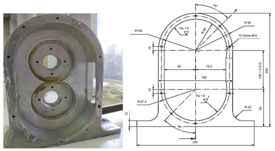
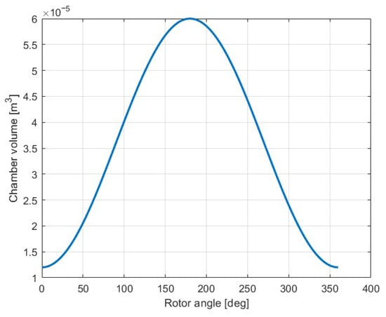
The geometric configuration of the profiled-rotor rotary compressor strongly influences chamber formation, sealing quality, and volumetric efficiency. To illustrate the rotor arrangement and chamber structure considered in the present numerical model, the cross-sectional geometry of the compressor is shown in Figure 1.
Figure 1.
Geometry of the profiled rotors and casing of the rotary compressor.
As shown in Figure 1, the interacting rotor profiles generate multiple closed chambers that evolve continuously during rotation. The profile design ensures permanent contact lines that limit internal leakage and provide stable separation between suction, compression, and discharge zones. This geometry forms the basis for defining the chamber volume variation law used in the numerical simulations.
The analytical volume function was compared with discrete chamber volumes from the CAD model at multiple rotor angles, confirming deviations below a few percent over the cycle. The deviations between the analytical approximation and CAD-based chamber volumes remain within a few percent over the full cycle. Sensitivity tests showed that small discrepancies have limited impact on global performance indicators, while local pressure peaks remain qualitatively consistent.
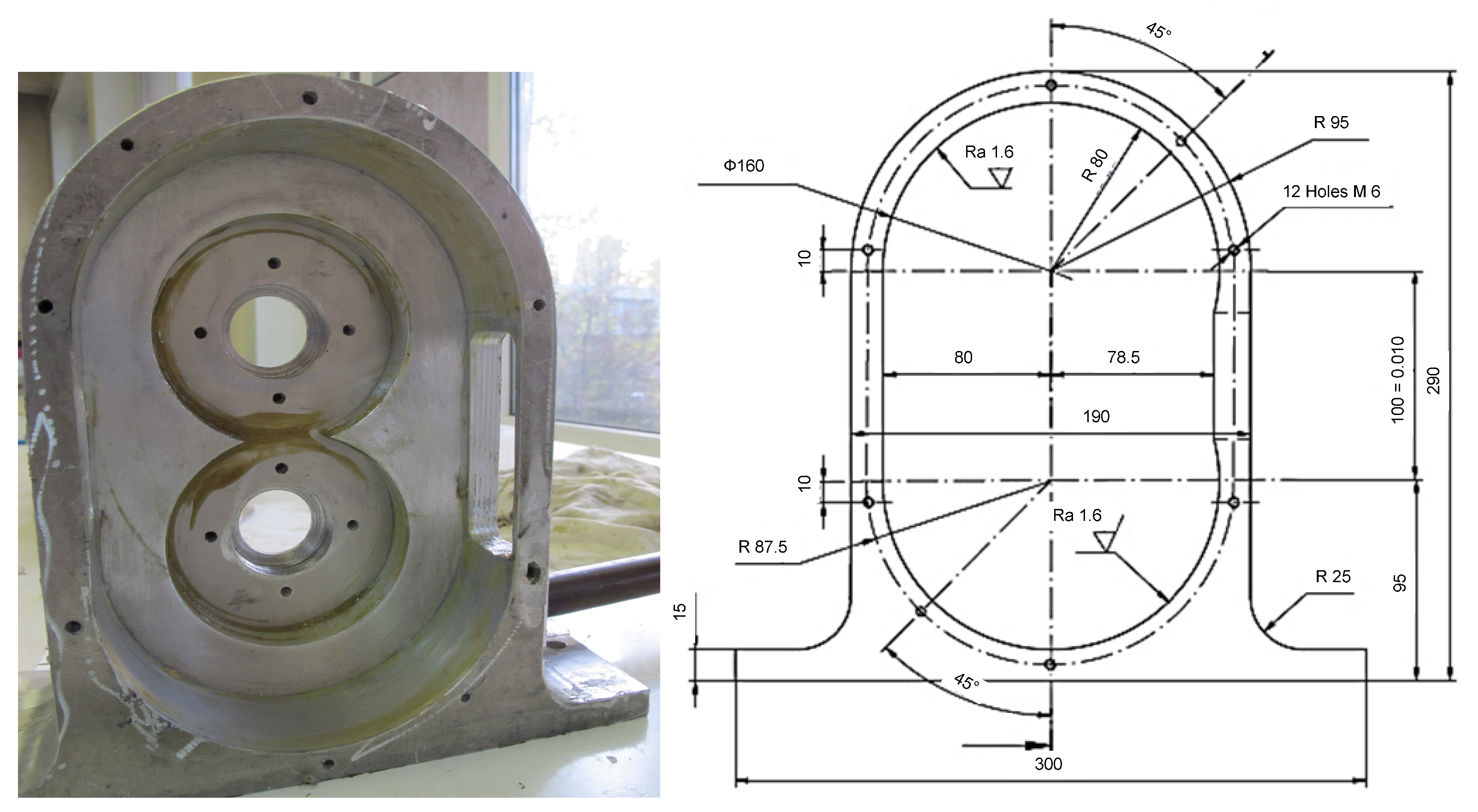
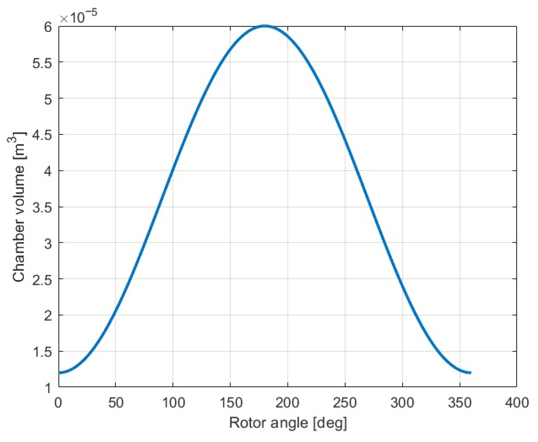
Figure 2 shows the chamber volume evolution over one compression cycle. The volume rises during suction, peaks before chamber isolation, and decreases smoothly during compression until discharge, reflecting the physical kinematics and ensuring numerical stability.
Figure 2.
Evolution of chamber volume as a function of rotor angle over one compression cycle of the profiled rotors and casing of the rotary compressor.
As observed in Figure 2, the chamber volume increases during the suction phase, reaches a maximum shortly before chamber isolation, and then decreases smoothly during the compression phase until the discharge port opening. This continuous variation ensures numerical stability and reflects the physical kinematics of profiled-rotor compressors. The minimum and maximum volume values are directly linked to the built-in volume ratio of the machine and strongly influence the achievable pressure ratio. This distinction between exact geometric volume laws and analytical approximations is typical in reduced-order chamber-based modeling approaches.
2.2. Governing Equations for Multiphase Compressible Flow
The present chamber-based formulation follows the general modeling philosophy introduced in classical studies of positive-displacement machines, including the work of [20], where the working chambers are treated as control volumes governed by conservation laws.
Each working chamber is modeled as a control volume with uniform thermodynamic properties at any given moment, a standard assumption in chamber-based compressor models [21,22,23,24]. Pressure and temperature evolve according to mass and energy conservation, accounting for mass transfer through suction and discharge ports and internal leakage paths.
The total mass inside the chamber is expressed as:
where mg is the mass of the gas phase and mv is the mass of vapor phase.
The vapor volume fraction is defined as:
where Vv the vapor volume and V is the total chamber volume.
The mass conservation equation is written as:
where m is the total mixture mass in the chamber, and are the inlet and outlet mass flow rates, respectively, modeled using quasi-steady orifice flow relations depending on the pressure difference between chambers and ports.
Mass flow through suction and discharge ports is modeled using quasi-steady compressible orifice relations:
where Cd is the discharge coefficient, A is the effective port area, and pu and pd are upstream and downstream pressures and ρ denotes the instantaneous density of the gas–vapor mixture inside the chamber. Leakage effects are not explicitly resolved through detailed geometric modeling of individual leakage paths (e.g., tip and interlobe clearances). Instead, they are implicitly incorporated into the effective discharge coefficient used in the quasi-steady mass flow relations. This coefficient is calibrated based on experimental mass flow rate measurements.
This approach represents a modeling simplification consistent with reduced-order chamber formulations, where leakage is treated in an averaged manner rather than as a spatially resolved flow phenomenon.
The energy conservation equation for the control volume corresponds to the classical open-system energy balance applied to a time-varying chamber, as commonly adopted in chamber-based models of rotary and screw compressors [20,21]:
where u is the specific internal energy of the mixture, p is pressure, V is chamber volume, and hin and hout are the specific enthalpies of inflowing and outflowing fluids. Heat transfer with the casing and rotors is modeled using a lumped heat transfer coefficient. The heat-transfer formulation is implemented within the lumped control-volume framework already assumed for the chamber model and contributes to the transient energy balance without introducing spatial resolution. Equation (7) represents a standard thermodynamic formulation and is not introduced as a novel contribution; its role is to provide the theoretical foundation for the proposed reduced-order chamber model.
The mixture thermodynamic properties are computed as weighted averages based on vapor volume fraction:
where α represents the vapor volume fraction defined in Equation (5) and subscripts g and v denote gas and vapor phases, respectively. The equation of state for the gas phase is assumed to follow the ideal gas law, while vapor properties are evaluated at saturation conditions corresponding to local pressure.
Within the present reduced-order formulation, heat transfer acts as a moderating mechanism for the temperature and pressure transients, influencing the global energy exchange and the predicted compression work.
2.3. Flow Cavitation and Vapor Fraction Criterion
Cavitation tendency is evaluated by comparing the chamber’s instantaneous pressure with the fluid’s saturation pressure. When local pressure drops below psat, vapor formation is assumed. A simplified cavitation indicator is given by:
To maintain numerical stability, the vapor fraction is updated through a relaxation-type source term:
where Kvap is an empirical coefficient controlling vapor formation rate. The mixture density is approximated by:
Vapor fraction is constrained between 0 and a maximum threshold. While simplified, this approach identifies rotor positions and operating regimes prone to cavitation, which is important for design optimization and operational safety. Notably, the model does not resolve individual bubble dynamics, collapse, or shock effects, treating cavitation as a thermodynamic tendency caused by local pressure falling below saturation.
This approach is suitable for identifying operating regimes and rotor positions where vapor formation may influence mixture compressibility, pressure evolution, and volumetric performance. These limitations are inherent to reduced-order chamber-based models and motivate future coupling with higher-fidelity multiphase simulations. The cavitation/vapor-fraction formulation is used as a thermodynamic indicator of operating regimes where local pressure drops may induce incipient phase change, rather than as a model for bubble dynamics, collapse, acoustic effects, or material erosion.
2.4. Numerical Integration Procedure
The governing equations are discretized in time using an explicit time-marching scheme synchronized with the rotor angular position. Heat transfer is modeled using a lumped coefficient approach, while leakage is represented through a simplified pressure-driven quasi-steady formulation.
Time is related to the rotor angle via rotational speed n [1]:
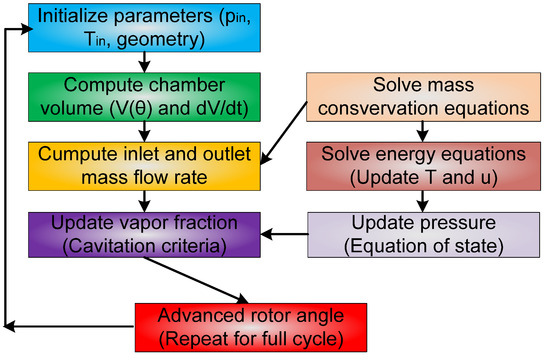
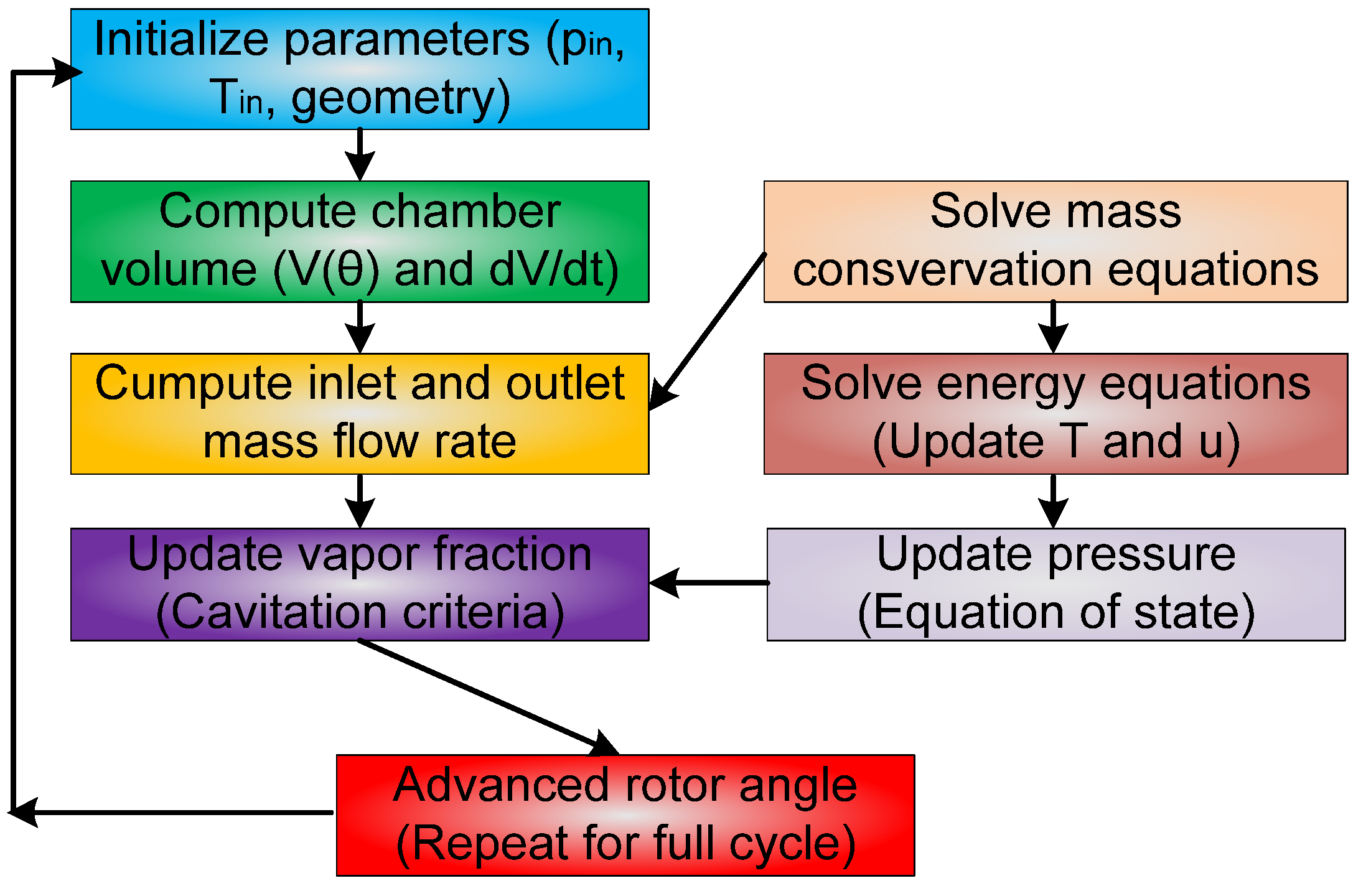
At each time step, the computational sequence from Figure 3 is applied.
Figure 3.
Computational workflow of the chamber-based numerical model implemented in MATLAB.
The system of equations is solved using the explicit Runge–Kutta using MATLAB’s built-in ODE solvers, such as ode45, ensuring numerical stability and adaptive time stepping. The explicit integration scheme was selected due to the moderate stiffness of the governing equations and the need to efficiently track fast transients associated with port opening and chamber isolation. Sensitivity tests were conducted by varying solver tolerances and time-step resolution, confirming that the predicted pressure and vapor fraction evolutions remain stable within acceptable numerical limits. This confirms the robustness of the chosen numerical approach for the investigated operating range. The model outputs include transient evolution of chamber pressure and temperature.
To clarify the numerical solution strategy and the coupling between geometric, thermodynamic, and multiphase sub-models, a computational workflow of the chamber-based simulation procedure is presented in Figure 3. The workflow summarizes the sequence of operations performed at each time step during the transient simulation of one compression cycle.
As illustrated in Figure 3, the simulation starts with initialization of geometric and thermodynamic parameters, followed by evaluation of chamber volume and its time derivative as functions of rotor position. Mass flow rates through suction and discharge ports are then calculated using quasi-steady flow relations. Subsequently, the conservation equations of mass and energy are solved to update pressure and temperature, and the vapor fraction is corrected based on the cavitation criterion. The procedure is repeated iteratively over successive rotor angles until convergence of periodic operating conditions is achieved. This modular structure allows easy extension of the model to include additional physical effects such as leakage, oil injection, or detailed heat transfer correlations.
MATLAB is used exclusively as a computational tool for implementing the numerical scheme and performing fast transient simulations, without representing any novelty in the programming environment itself.
The novelty of the present work does not lie in the governing equations themselves, but in their integration into a reduced-order multiphase chamber model, the inclusion of a simplified cavitation tendency criterion, and the experimental validation on a profiled-rotor rotary compressor.
2.5. Operating Conditions and Model Inputs
The main operating conditions and model inputs used in the present study are summarized below to ensure clarity, reproducibility, and consistency between numerical simulations and experimental validation.
The working fluid is air, modeled as an ideal gas. The working process is treated as a gas–vapor mixture under incipient cavitation conditions. Vapor formation is evaluated based on the instantaneous local pressure relative to the saturation pressure, without resolving detailed bubble dynamics. The compressor operates under experimentally controlled conditions in an open-loop test bench configuration. The suction pressure corresponds to ambient atmospheric conditions (approximately 1 bar), while the discharge pressure is regulated using a throttling valve, covering a range of operating points within the compressor’s stable operating envelope.
The suction temperature is assumed to be close to ambient conditions, as measured during experiments, typically in the range of approximately 293–300 K depending on operating conditions. The rotational speed is varied across multiple operating points, spanning the range defined in the experimental campaign (n1 to n2 rpm), which is consistent with the data sets used for validation of the numerical model.
The chamber geometry is defined based on CAD-derived rotor and casing profiles. The chamber volume varies between a minimum and maximum value (Vmin and Vmax) over one rotor cycle. These values define the built-in volume ratio of the compressor, which governs the overall compression ratio. The time evolution of chamber volume is approximated using a smooth analytical cosine-based function calibrated against CAD geometry, ensuring numerical stability and continuous derivatives for transient simulation.
Heat transfer between the working fluid and the solid boundaries (rotors and casing) is modeled using a lumped heat transfer coefficient approach. Leakage flows between adjacent chambers and through clearances are modeled using quasi-steady compressible orifice relations driven by instantaneous pressure differences. The governing equations are solved in MATLAB using an explicit Runge–Kutta scheme with adaptive time stepping (ode45). This approach allows for accurate resolution of transient effects associated with port opening, chamber isolation, and rapid pressure variation.
The above parameters define the boundary conditions for both numerical simulations and experimental measurements, ensuring direct comparability between predicted and measured performance indicators.
3. Experimental Setup for Validation
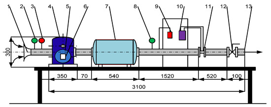
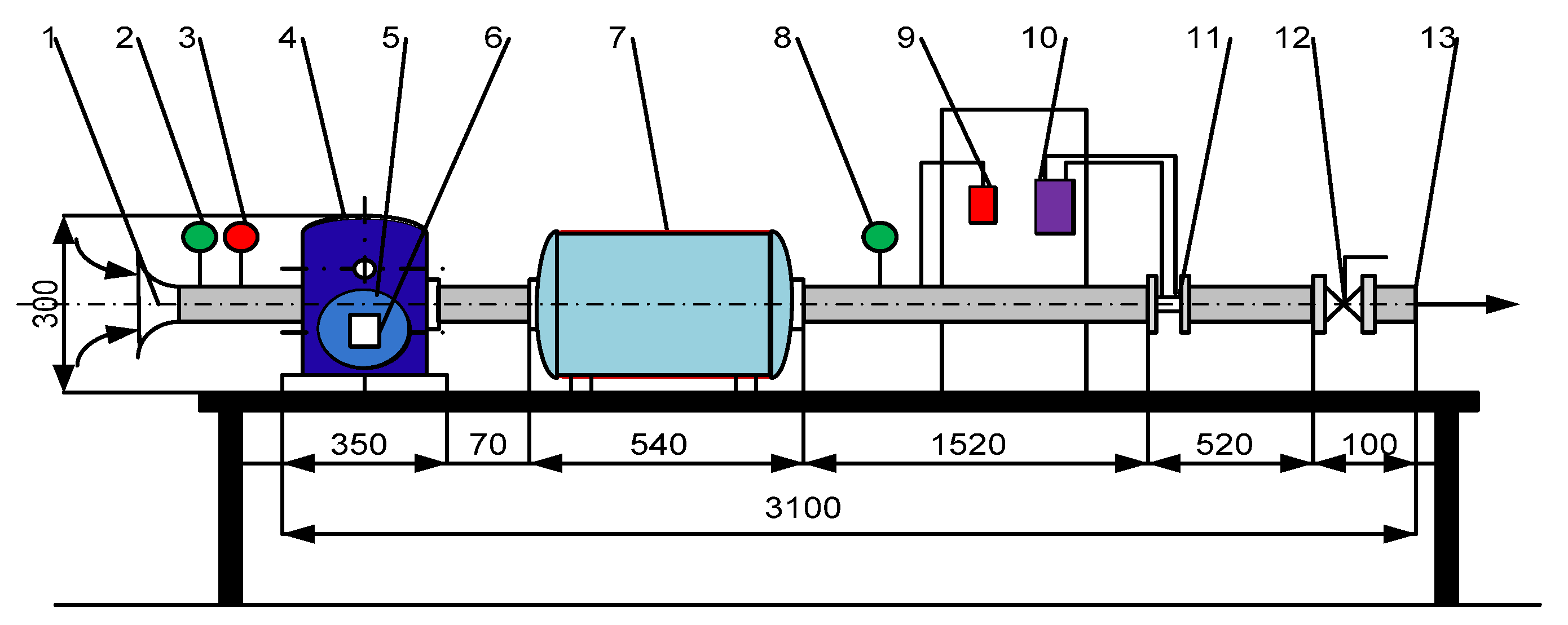
To validate the chamber-based multiphase model, an experimental campaign was carried out using a dedicated open-loop test bench designed for rotary volumetric compressors. The bench allows for controlled changes in rotational speed and discharge pressure while monitoring thermodynamic and mechanical parameters. Figure 4 provides a schematic of the installation, showing the airflow path and measurement sections.
Figure 4.
Schematic diagram of the open-loop experimental test bench for the rotary compressor. 1—air filter; 2—pressure gauge; 3—thermometer; 4—rotary compressor; 5—electric motor; 6—ALTIVAR device; 7—compressed air tank; 8—pressure gauge with digital display; 9—thermometer with digital display; 10—differential pressure gauge; 11—diaphragm; 12—air flow control valve; 13—air exhaust connection Dn 50.
The experiments were performed over explicitly defined operating ranges of rotational speed and discharge pressure, which directly correspond to the boundary conditions used in the numerical model.
As illustrated in Figure 4, ambient air is drawn into the compressor through a calibrated intake section, passes through the compression chamber, and is discharged into an adjustable throttling system that controls the outlet pressure. The airflow then passes through a measurement section before being released into the atmosphere. This configuration enables stable steady-state operation over a wide range of pressure ratios and rotational speeds, which is essential for reliable comparison with numerical simulations.
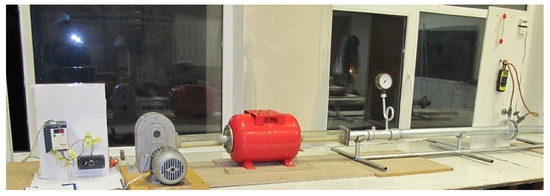
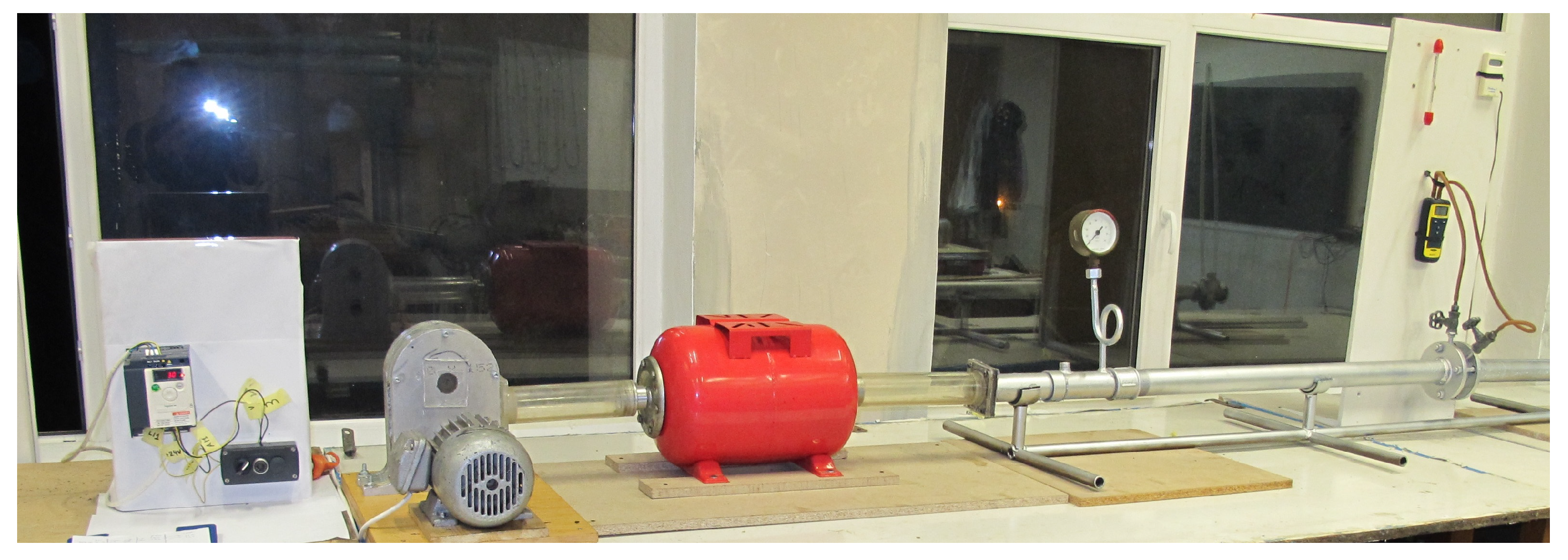
The compressor is mounted on a rigid test frame with the electric drive motor, coupling, and support structure, ensuring precise shaft alignment and minimizing vibrations (Figure 5).
Figure 5.
Photograph of the rotary compressor mounted on the experimental test bench.
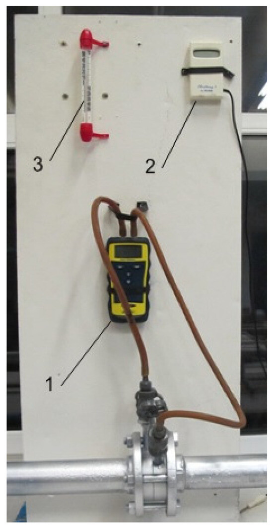
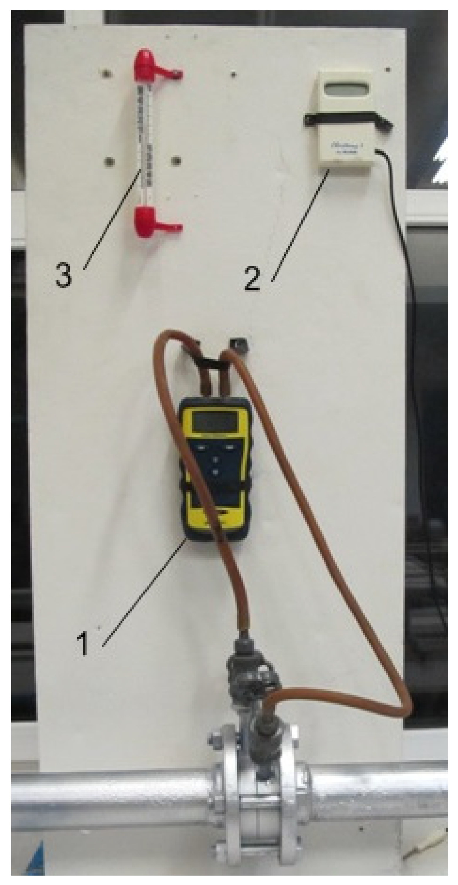
Pressure and temperature sensors are installed near suction and discharge ports, as illustrated in Figure 6.
Figure 6.
Instrumentation layout. 1—manometer Digitron PM 20; 2—thermometer CHECKTEMP 1 HI 98509 HANNA Instruments France; 3—mercury thermometer.
The mass flow rate is measured downstream with a calibrated flow meter, while electrical power input is recorded using a digital power analyzer. Multi-channel data acquisition captures synchronized signals, and measurements are averaged over at least 60 s to reduce short-term fluctuations. Measurement uncertainties were quantified for pressure (±1.0%), temperature (±0.5 K), and mass flow rate (±1.5%), and were considered in the validation of numerical results. Experimental data are averaged over a time window of at least 60 s to reduce short-term fluctuations and improve signal stability. The experimental operating conditions investigated in this study include rotational speeds ranging from n1 to n2 rpm and discharge pressures between p1 and p2 bar, covering the typical operating envelope of the compressor prototype. These conditions are consistent with those used as boundary inputs in the numerical simulations, enabling direct comparison between measured and predicted performance parameters.
4. Results and Discussion
This section presents the numerical and experimental results obtained for the profiled-rotor rotary compressor and discusses the influence of transient chamber dynamics and multiphase effects on global performance indicators. The comparison focuses on pressure evolution, vapor fraction development, mass flow rate, and power consumption under different operating conditions. The results are interpreted in terms of thermodynamic effects associated with heat transfer, leakage losses, and multiphase compressibility within the limitations of the reduced-order model. The thermal interaction between the working fluid and the compressor structure contributes to smoothing temperature evolution during the compression cycle, with indirect effects on pressure development and power prediction.
4.1. Transient Pressure Evolution in the Working Chamber
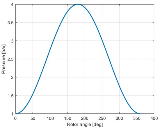
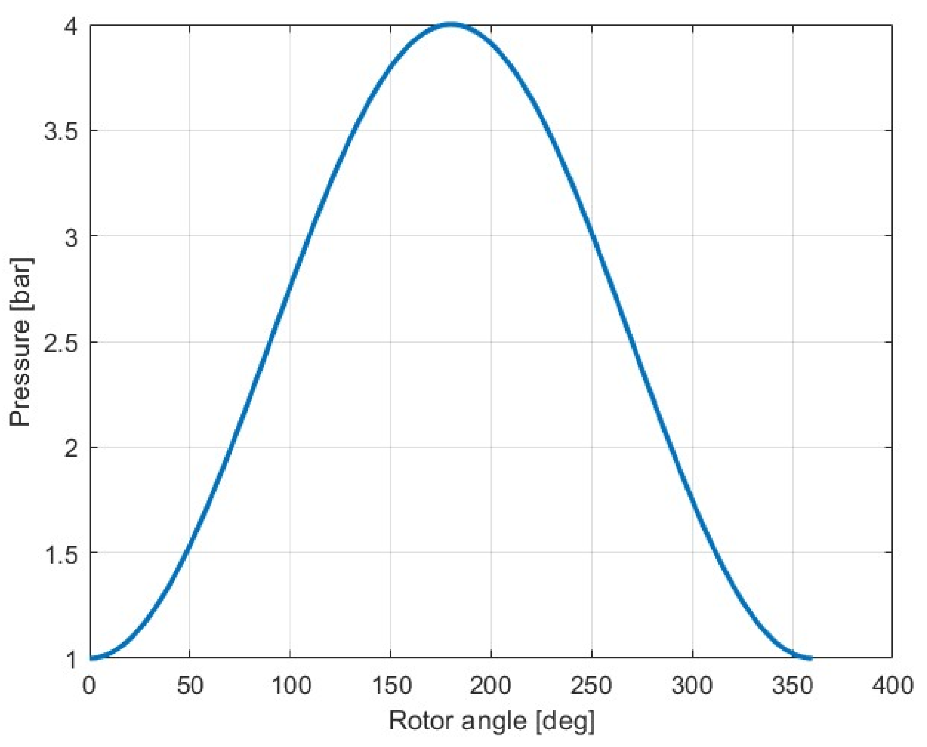
The transient evolution of chamber pressure over a full compression cycle is a key indicator of internal thermodynamic behavior. Figure 7 shows the numerically predicted chamber pressure as a function of rotor angle for a representative operating condition, along with the corresponding experimental discharge pressure.
Figure 7.
Numerical prediction of transient chamber pressure versus rotor angle during one compression cycle.
As seen in Figure 7, pressure rises smoothly during compression and reaches the discharge level near the outlet port opening. The absence of sharp spikes indicates stable compression and limited internal leakage between chambers. During the suction phase, pressure remains near the inlet level, then rises rapidly as the chamber becomes isolated and volume decreases. Small oscillations observed in the numerical pressure evolution are associated with mass flow transitions during port opening and closure. Although direct transient pressure measurements inside the working chamber are not available, the predicted oscillations are consistent with pressure fluctuations reported in experimental and numerical studies of similar rotary positive-displacement machines. These oscillations reflect transient flow adjustments rather than numerical artifacts.
4.2. Vapor Volume Fraction and Cavitation Tendency
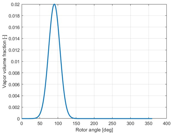
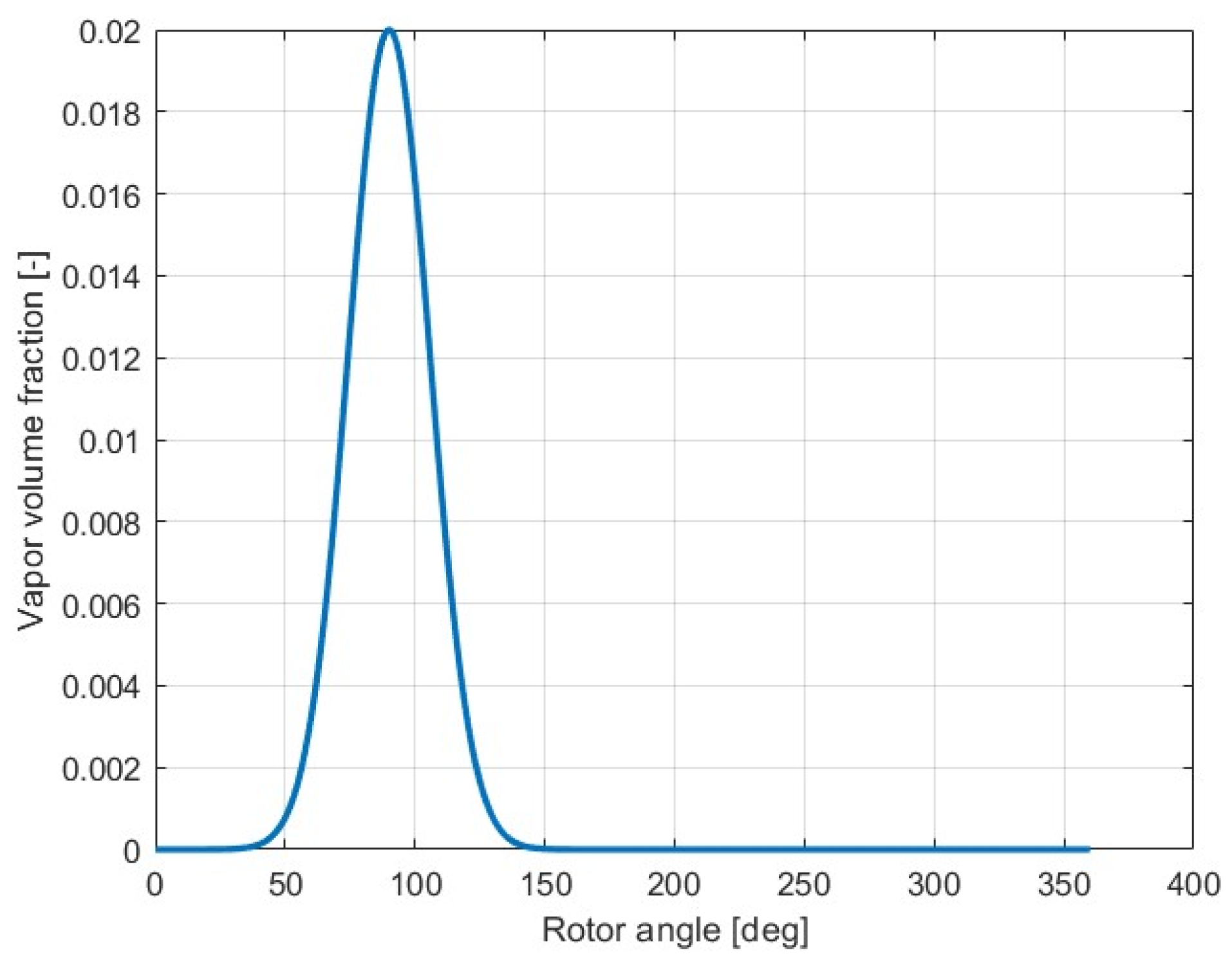
The evolution of vapor volume fraction during the compression cycle is monitored to assess multiphase behavior and cavitation tendency. Figure 8 presents the predicted vapor fraction versus rotor angle for the same operating condition as Figure 7.
Figure 8.
Predicted vapor volume fraction in the working chamber over one compression cycle.
The identified vapor formation corresponds to transient low-pressure regions occurring during suction and early compression, where rapid volume expansion can locally reduce pressure below saturation conditions.
Vapor forms mainly during the suction phase, when rapid chamber expansion and accelerated flow can locally reduce pressure below the saturation threshold. Most of the cycle shows low vapor fractions, indicating incipient rather than fully developed cavitation. The observed multiphase effects correspond to incipient cavitation with small vapor fractions. Once compression starts and pressure rises above saturation, vapor collapses quickly, returning the chamber to a single-phase gas state. Although the vapor fraction remains small, it modifies the effective compressibility of the mixture, which in turn influences the early compression pressure evolution. While the model does not track individual bubble dynamics, the vapor fraction trends highlight rotor positions and operating regimes where multiphase effects could affect volumetric efficiency and mechanical load. This underscores the relevance of cavitation tendency even in gas compressors, especially with lubricants or condensable vapors. Cavitation tendency is identified based on the pressure-based criterion defined in Equation (9), rather than direct visualization of vapor structures.
4.3. Validation of Global Performance Parameters
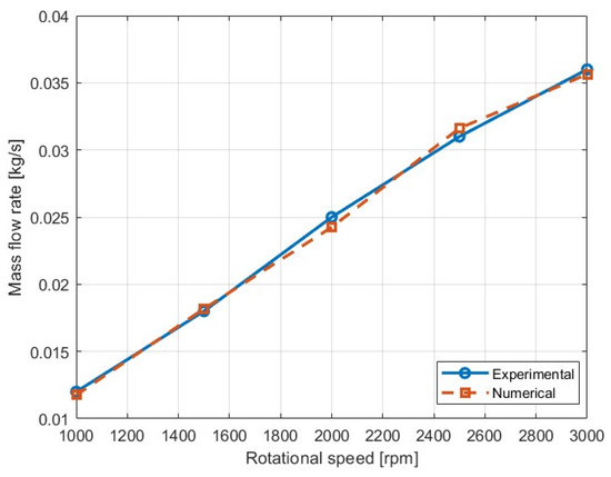
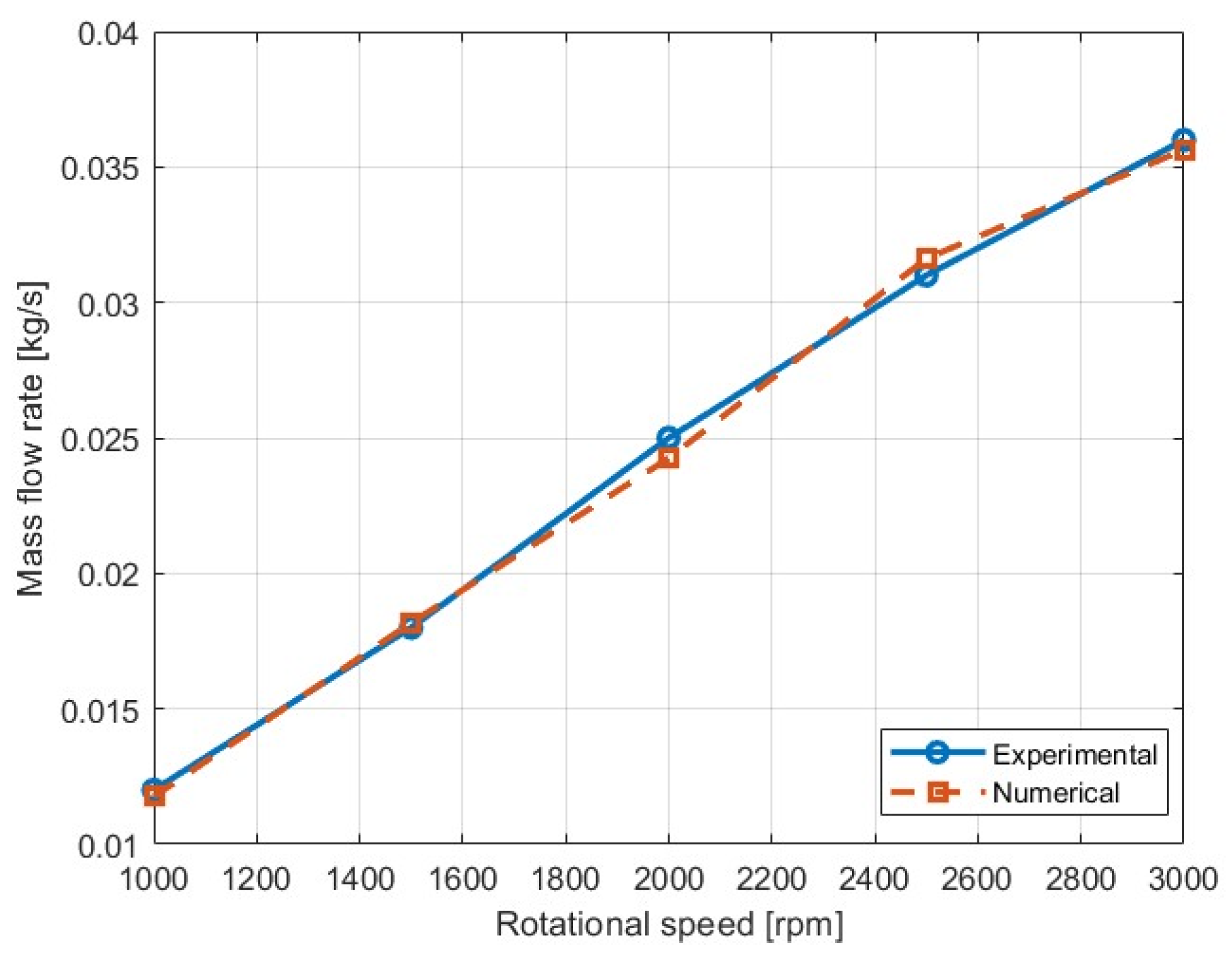
To validate the model quantitatively, numerical predictions are compared with experimental global performance indicators. Figure 9 shows the mass flow rate from experiments alongside numerical predictions across a range of rotational speeds.
Figure 9.
Comparison between experimental and numerical mass flow rates as a function of rotational speed.
The model reproduces the experimental trends accurately, with deviations below about 5%, which falls within combined measurement and modeling uncertainties.
The agreement between numerical and experimental mass flow rates indicates that the effective discharge coefficient successfully captures the overall impact of leakage within the investigated operating range.
To quantitatively assess the agreement between numerical predictions and experimental data, the mean absolute percentage error (MAPE) was evaluated for the mass flow rate and power consumption over all investigated operating points. The MAPE was calculated according to:
where Xnum,i and Xexp,i denote numerical and experimental values, respectively, and N is the number of operating points considered. The resulting MAPE values remained below 5% for both mass flow rate and power, confirming the quantitative agreement between the numerical model and experimental measurements
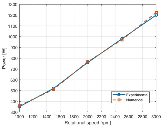
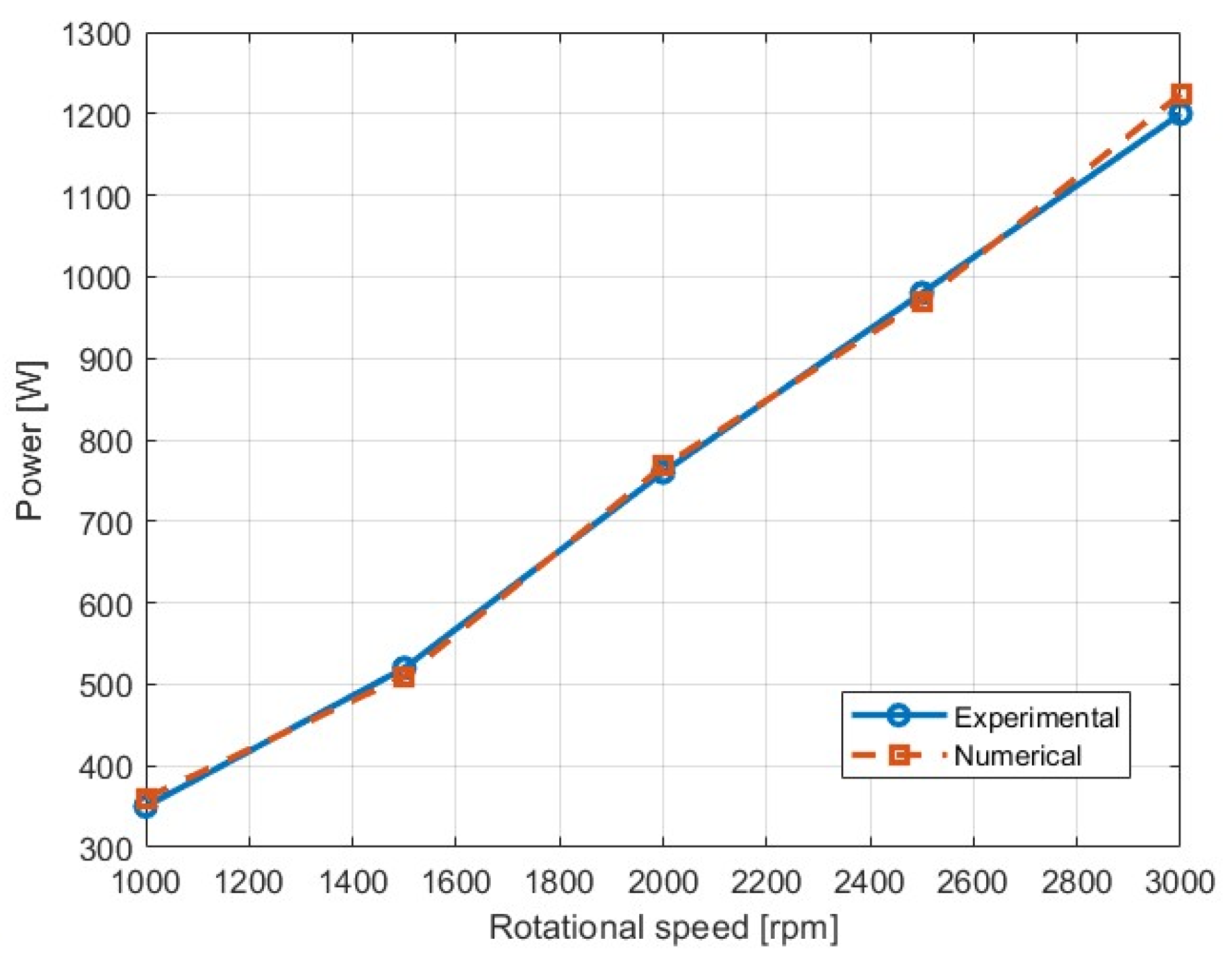
Slight underprediction at higher speeds may result from increased leakage and dynamic effects not fully captured by the quasi-steady flow relations. Electrical power consumption is also compared, with Figure 10 showing measured input power and numerically estimated compression power. Good agreement confirms that the model captures the main compression work mechanisms.
Figure 10.
Experimental versus numerical power consumption for different operating conditions.
Remaining deviations mainly relate to mechanical losses and motor efficiency variations, which could be included with correction factors in future work. The mean absolute percentage error (MAPE) remains below 5% for both mass flow rate and power, demonstrating the model’s predictive capability within experimental uncertainties. The reported MAPE values should therefore be interpreted in the context of both measurement uncertainty and modeling assumptions. Remaining deviations at higher rotational speeds and pressure ratios can be partially attributed to leakage effects not explicitly resolved in the model, as well as increased flow dynamics not captured by the quasi-steady formulation. The deviations between numerical and experimental results fall within the combined range of experimental uncertainty and model simplifications.
4.4. Influence of Multiphase Effects on Compressor Performance
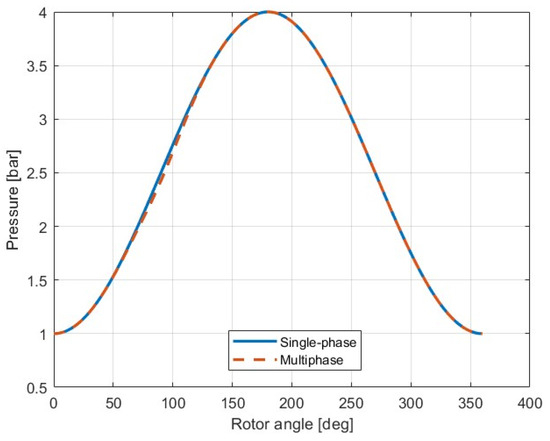
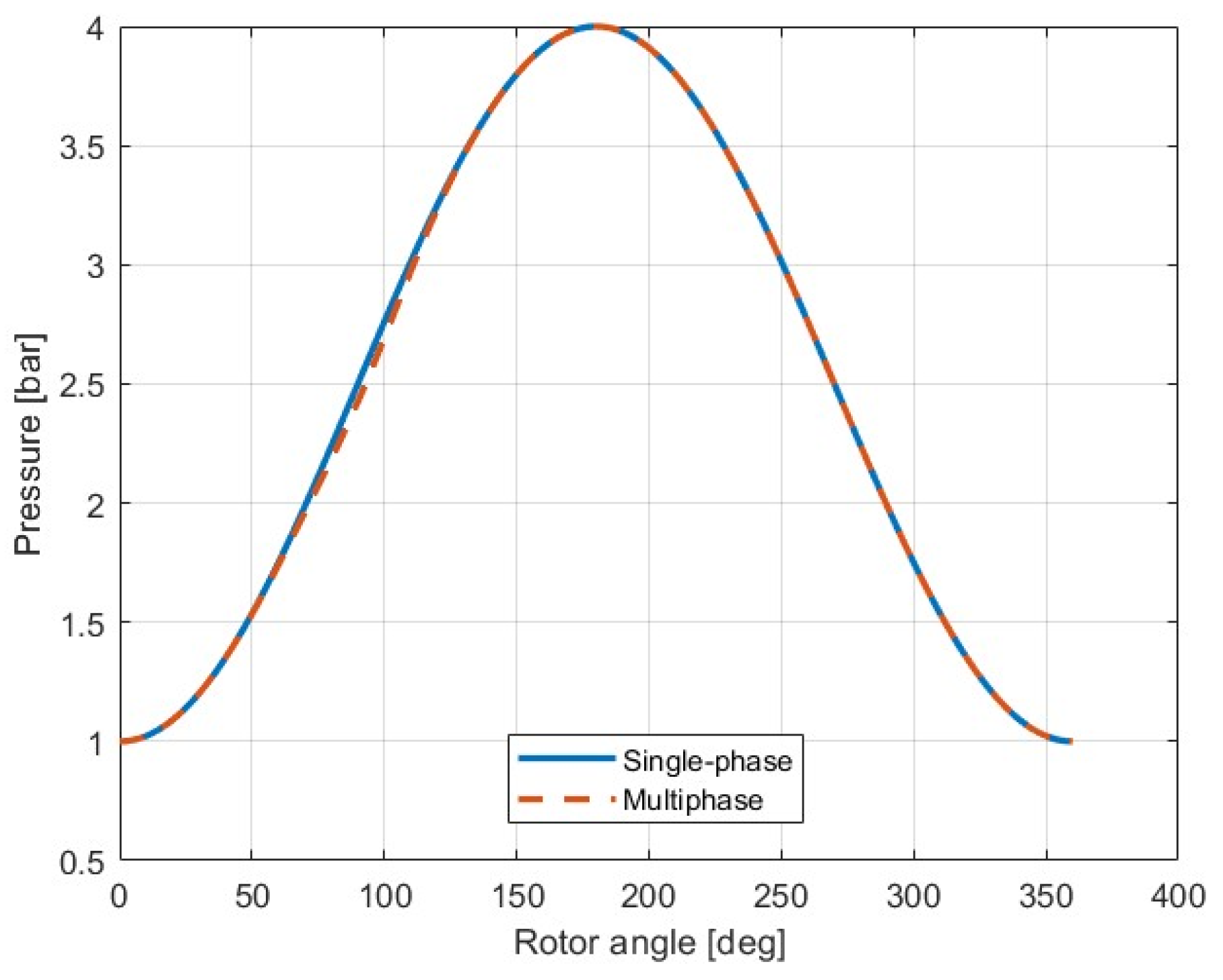
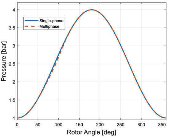
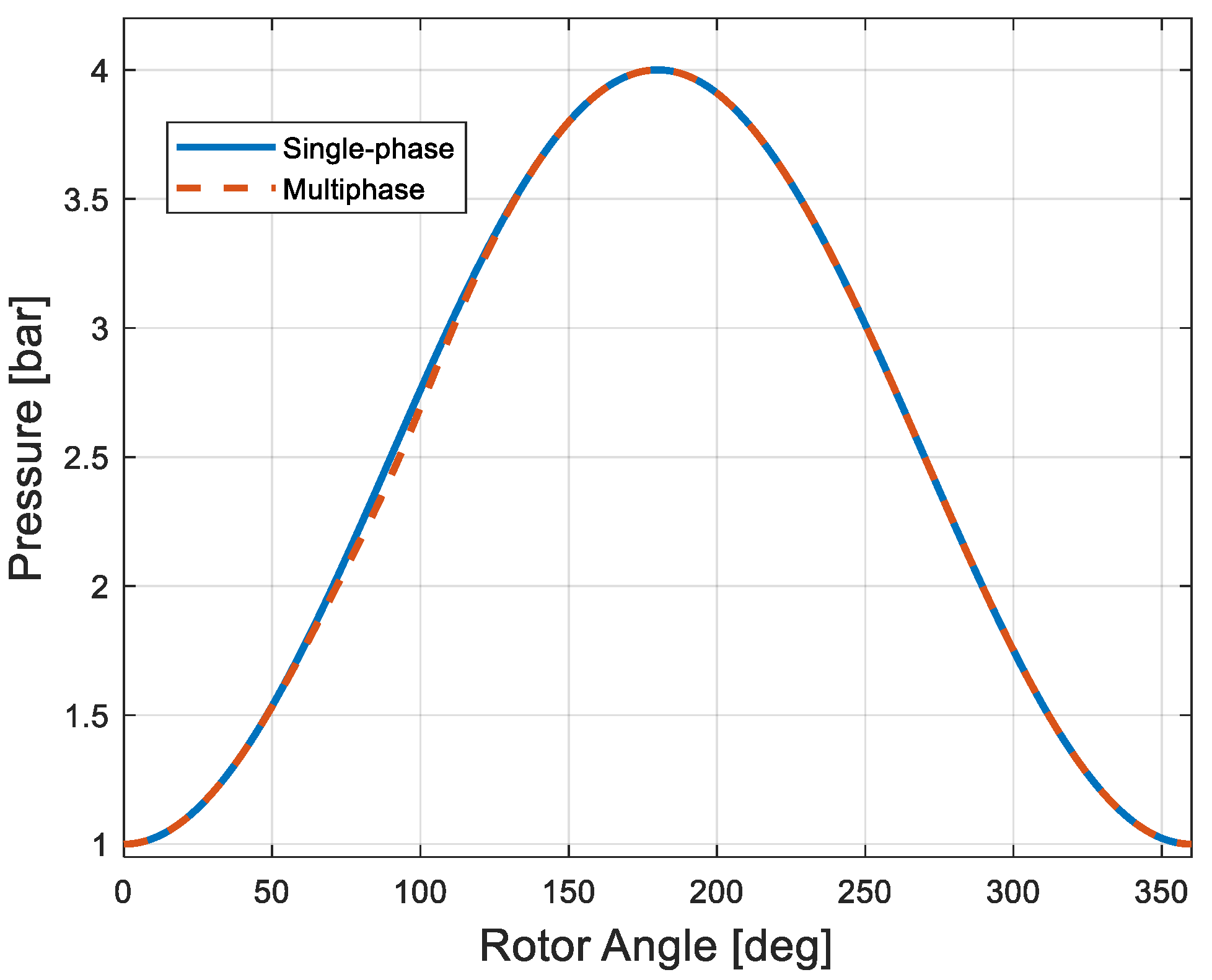
To assess the influence of multiphase behavior on global performance, simulations were performed with and without vapor fraction modeling. Figure 11 shows how vapor formation affects predicted chamber pressure and effective compression work.
Figure 11.
Comparison of pressure evolution with and without vapor fraction modeling.
The results show that although the multiphase effect is relatively small, it is systematic and leads to consistent modifications in pressure evolution and compression work.
The presence of vapor slightly delays the pressure rise during early compression due to the increased compressibility of the mixture. While this effect is modest under the tested conditions, it becomes more noticeable at lower suction pressures and higher rotational speeds. Even small delays in pressure rise can impact volumetric efficiency and compression work, especially near design limits. These results emphasize the importance of including multiphase compressibility effects in reduced-order compressor models used for preliminary design and optimization.
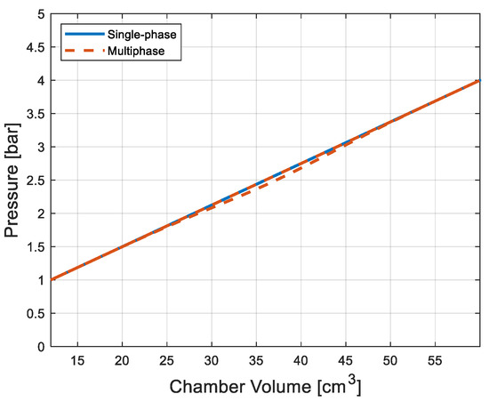
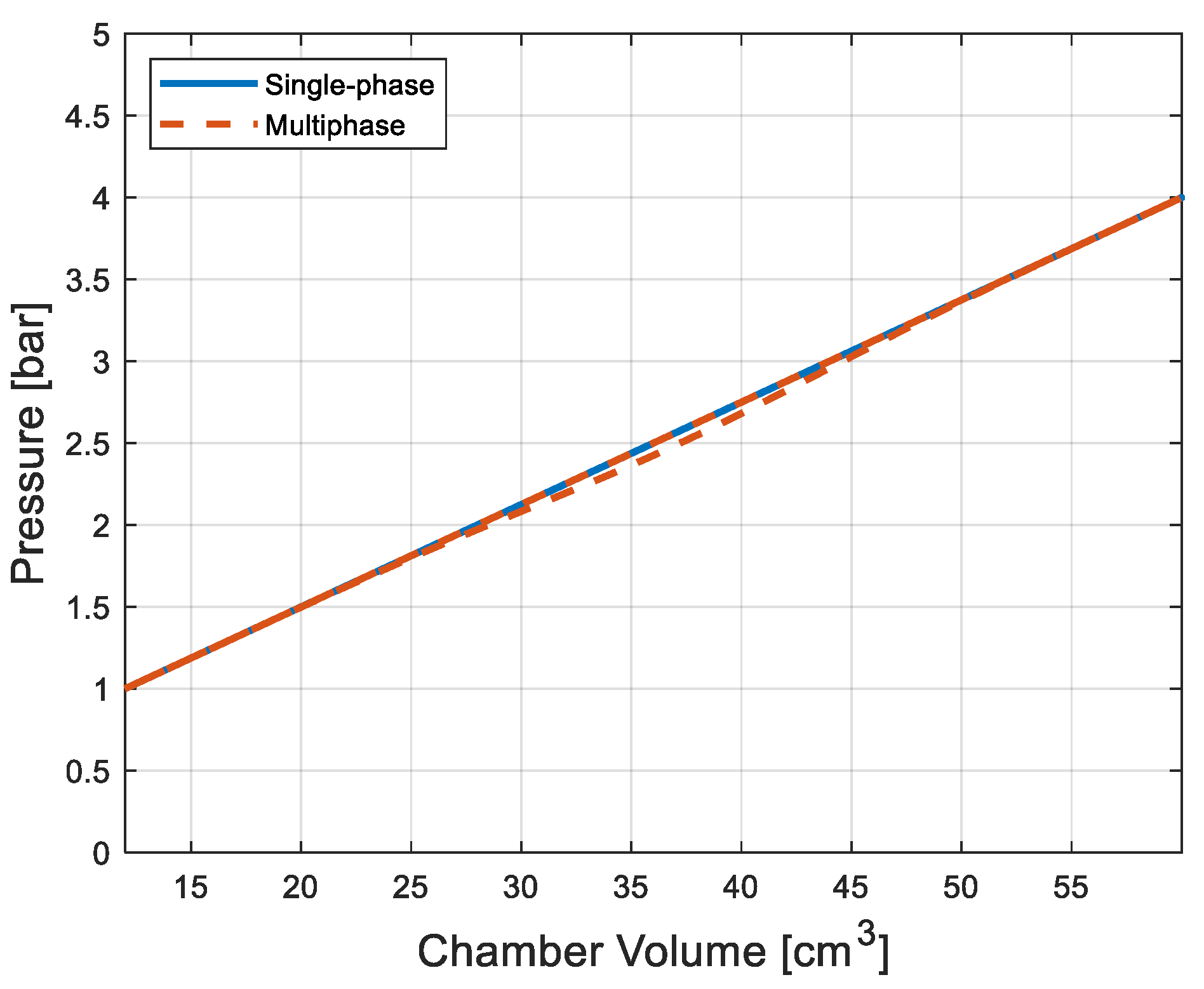
The cavitation tendency may also affect compressor stability and efficiency in operating regimes close to design limits, as illustrated by the pressure–volume behavior and compression work deviations shown in Figure 12 and Figure 13.
Figure 12.
Pressure–volume diagram for single-phase and multiphase chamber models.
Figure 13.
Indirect experimental p–V representation.
Overall, these results demonstrate that even simplified multiphase modeling provides useful insight for design optimization and risk assessment, particularly when combined with fast, low-order simulations suitable for parametric studies or digital-twin applications. To address the concern regarding the limited magnitude of multiphase effects, a comparative analysis with and without vapor fraction modeling is performed. Therefore, the purpose of the multiphase model is not to predict erosion or fully developed cavitation, but to identify trends and provide thermodynamic insight, particularly near design operating limits.
4.5. Thermodynamic Interpretation of Multiphase Effects
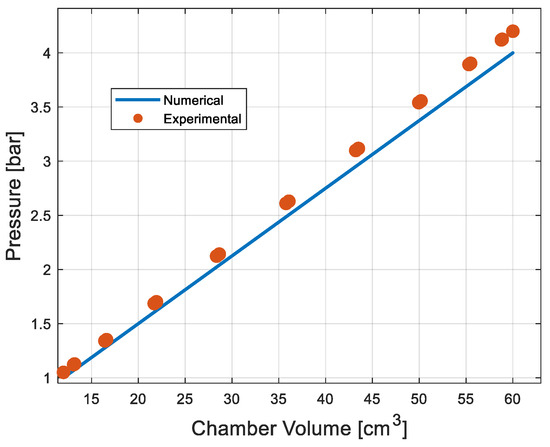
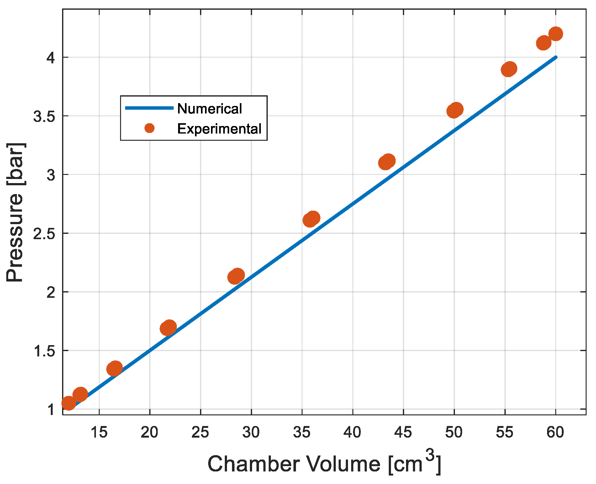
Direct transient in-chamber pressure–volume measurements are not experimentally available due to the rotating geometry and limited accessibility for in situ instrumentation. Therefore, all pressure–volume (p–V) diagrams presented in this study are obtained from the numerical chamber model.
Thermodynamic quantities from the numerical chamber model are interpreted using experimentally validated boundary conditions and measured global performance parameters, allowing for an indirect assessment of compression work and pressure–volume behavior.
Each chamber’s compression process can be seen as a highly unsteady open-system transformation, with continuous changes in pressure, temperature, and volume. Even limited amounts of vapor modify the effective compressibility of the working fluid, altering the pressure–volume trajectory in early compression.
From a thermodynamic point of view, the compression work associated with a single chamber over one cycle can be expressed as the pressure–volume integral:
where p is the instantaneous chamber pressure and V is the time-varying chamber volume. Vapor presence changes the mixture compressibility, causing deviations from single-phase compression.
Effective mixture compressibility relates qualitatively to the vapor volume fraction α through the mixture density, directly influencing pressure response during rapid volume reduction:
Small vapor fractions increase compliance, delaying the early compression pressure rise.
Figure 12 compares the pressure–volume diagram of a representative chamber for single-phase and multiphase models.
An indirect experimental reference is provided in Figure 13, which uses measured discharge pressure and effective chamber volume derived from the geometric compression ratio. This allows for a thermodynamically consistent comparison between numerical and experimental conditions.
Experimental data are used indirectly for validation through boundary conditions and global performance indicators, rather than direct in-chamber p–V measurement.
Vapor formation during suction causes a slight delay in pressure rise once the chamber is isolated. Thermodynamically, this redistributes compression work over a larger volume change, modifying the p–V work integral. Although modest under tested conditions, this effect becomes more relevant at high rotational speeds and low inlet pressures, where rapid volume changes amplify transient effects (Figure 14).
Figure 14.
Comparison of transient chamber pressure with and without vapor fraction modeling.
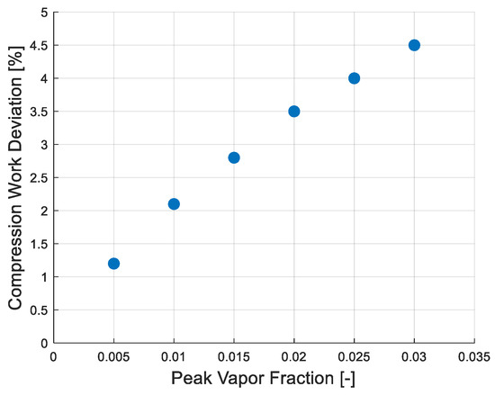
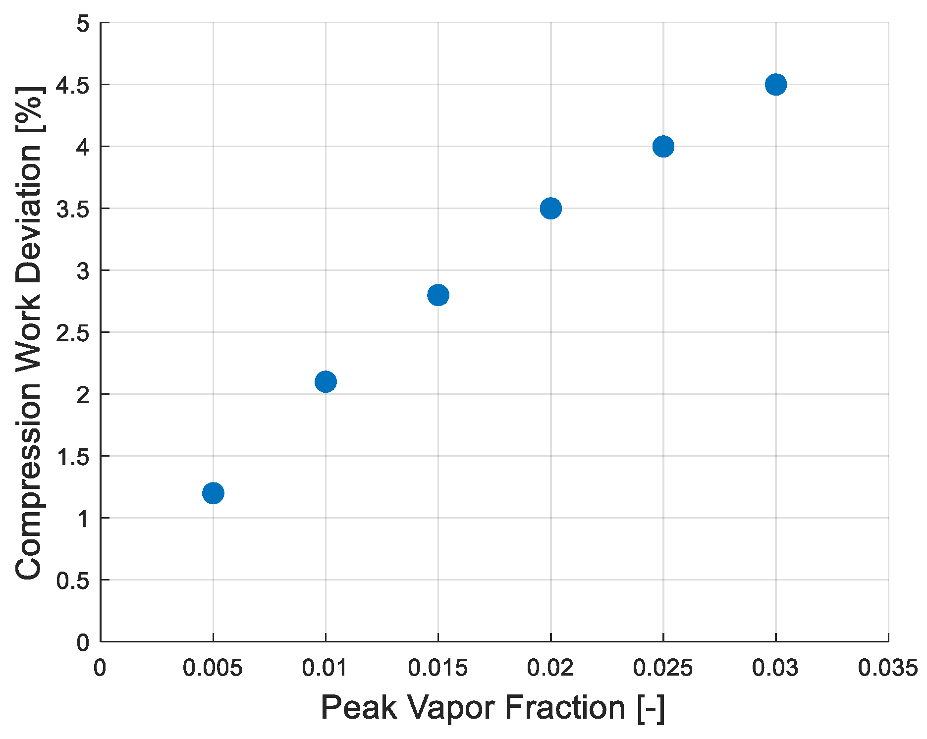
From an energy balance perspective, the mixture formulation captures temporary internal energy storage from phase changes without explicitly resolving bubble dynamics. This highlights operating regimes where multiphase effects may increase irreversibilities and reduce volumetric efficiency. Figure 15 quantifies how peak vapor fraction correlates with deviations in chamber compression work.
Figure 15.
Correlation between peak vapor fraction and deviations in chamber compression work.
Results show that higher vapor content systematically reduces effective compression work due to enhanced mixture compressibility, confirming the thermodynamic impact of incipient multiphase effects. These findings indicate that even minor multiphase effects can affect pressure–volume work and transient efficiency, which becomes increasingly important near design limits. This emphasizes the need for thermodynamically consistent reduced-order models in compressor analysis.
5. Conclusions
This study presents a chamber-based thermodynamic model for the transient analysis of a rotary positive-displacement compressor, with particular emphasis on multiphase effects and cavitation tendency. The model combines geometric, thermodynamic, and simplified multiphase formulations to capture the unsteady evolution of pressure, temperature, and vapor volume fraction within individual working chambers.
The pressure–volume analysis is based entirely on numerical reconstruction, supported indirectly by experimentally validated boundary conditions and global performance measurements.
Numerical results demonstrate that the proposed model accurately reproduces the transient pressure evolution and global performance indicators, with quantitative deviations assessed through mean absolute percentage error values remaining below 5% within the investigated operating range.
The inclusion of a simplified vapor-fraction model enables identification of operating conditions and rotor positions prone to incipient cavitation. Although vapor formation remains limited under the investigated conditions, even small vapor fractions were found to modify effective compressibility, delay pressure rise during early compression and alter the pressure–volume work distribution. These results indicate that multiphase effects contribute to transient energy redistribution and may influence compressor efficiency, particularly at low suction pressures and high rotational speeds near design limits.
Heat transfer, modeled through a lumped parameter approach, provides a secondary but thermodynamically consistent contribution to the overall energy balance and performance prediction.
The reduced-order nature of the proposed formulation provides a computationally efficient framework suitable for preliminary design, performance analysis, and parametric studies, making it particularly attractive for digital-twin applications and early-stage optimization where rapid evaluation of operating trends is required.
Leakage effects are accounted for in an averaged manner through calibrated discharge coefficients, representing a deliberate simplification consistent with the reduced-order modeling framework. The validation procedure incorporates both quantified measurement uncertainties and temporal averaging, providing a more robust basis for comparisons between numerical and experimental results.
Future developments may include refined leakage modeling, explicit representation of mechanical losses, and extended multiphase formulations applicable to broader operating conditions and alternative working fluids. Nevertheless, the present results demonstrate that even simplified multiphase modeling can provide valuable insights into the thermodynamic behavior and performance limits of rotary positive-displacement compressors.
Author Contributions
Conceptualization, M.C. and A.D.; methodology, M.C. and C.D.; software, M.C.; validation, A.D.; formal analysis, A.D. and C.D.; investigation, M.C.; resources, M.C., A.D. and C.D.; data curation, M.C. and A.D.; writing—original draft preparation, M.C. and C.D.; writing—review and editing, A.D. and C.D.; visualization, M.C., A.D. and C.D.; supervision, M.C.; project administration, A.D.; funding acquisition, M.C. and C.D. All authors have read and agreed to the published version of the manuscript.
Funding
This research received no external funding.
Data Availability Statement
The original contributions presented in this study are included in the article. Further inquiries can be directed at the corresponding authors.
Acknowledgments
During the preparation of this manuscript, the authors used ChatGPT, GPT-5.3 (OpenAI) solely for language-related assistance, including proofreading, grammar checking, and minor stylistic editing to improve clarity and readability. The tool was not used for generating scientific content, data, interpretations, or conclusions. The authors have carefully reviewed and edited the text and take full responsibility for the content of this publication.
Conflicts of Interest
The authors declare no conflicts of interest.
References
- Li, Y.; Zhao, X.; Liu, S.; Wang, C.; Shen, S.; Guo, Y. Review and prospects of numerical simulation research on internal flow and performance optimization of twin-screw compressors. Energies 2025, 18, 2608. [Google Scholar] [CrossRef] [Scilit]
- Wang, T.; Qi, Q.; Zhang, W.; Zhan, D. Research on Optimization of Profile Parameters in Screw Compressor Based on BP Neural Network and Genetic Algorithm. Energies 2023, 16, 3632. [Google Scholar] [CrossRef] [Scilit]
- Matuzović, M.; Rane, S.; Patel, B.; Kovačević, A.; Tuković, Ž. Analysis of Conjugate Heat Transfer in a Roots Blower and Validation with Infrared Thermography. Int. J. Thermofluids 2022, 13, 100234. [Google Scholar] [CrossRef] [Scilit]
- Wen, C.; Bai, P.; Zhang, H.; Zhang, S.; Meng, X.; Meng, Y.; Tian, Y. Theoretical Model Development and Mixed Lubrication Analyses of Rolling Piston Type Rotary Compressors: A Review. Lubricants 2024, 12, 273. [Google Scholar] [CrossRef] [Scilit]
- Abdan, S.; Patil, S.; Stosic, N.; Kovacevic, A. Experimental Validation of the Screw Compressor Oil Drag Model for Various Rotor Profiles. Proc. Inst. Mech. Eng. Part E J. Process Mech. Eng. 2023, 238, 2740–2749. [Google Scholar] [CrossRef] [Scilit]
- Kaufmann, F.; Irrgang, L.; Schifflechner, C.; Spliethoff, H. Fast and Accurate Modelling of Twin-Screw Compressors: A Generalised Low-Order Approach. Appl. Therm. Eng. 2024, 257, 124238. [Google Scholar] [CrossRef] [Scilit]
- Kumar, A.; Patil, S.; Kovacevic, A.; Ponnusami, S.A. Performance Prediction and Bayesian Optimization of Screw Compressors Using Gaussian Process Regression. Eng. App. Artif. Intell. 2024, 131, 108270. [Google Scholar] [CrossRef] [Scilit]
- Liu, Y.; Wang, Z.-N.; Tan, L.; Tucker, P.G.; Möller, F.M. Tip-Leakage-Flow Excited Unsteadiness and Associated Loss Mechanisms in Compressors. Phys. Fluids 2024, 36, 055156. [Google Scholar] [CrossRef] [Scilit]
- Rendu, Q.; Salles, L. Development of a Surrogate Model for Uncertainty Quantification of Compressor Performance Due to Manufacturing Tolerance. GPPS Proc. 2023, 7, 257–268. [Google Scholar] [CrossRef] [Scilit]
- Petrescu, V.; Savescu, C.; Stanescu, T.; Nechifor, C.; Niculescu, F.; Tomescu, S.; Vasile, E. Experimental Analysis of Twin Screw Compressor Efficiency. Eng. Technol. Appl. Sci. Res. 2024, 14, 6425. [Google Scholar] [CrossRef] [Scilit]
- Geist, S.; Schatz, M. Droplet-Laden Flows in Multistage Compressors: An Overview of the Impact of Modeling Depth on Calculated Compressor Performance. Int. J. Turbomach. Propuls. Power 2025, 10, 36. [Google Scholar] [CrossRef] [Scilit]
- Francesconi, M.; Baldinelli, A.; Sani, L.; Antonelli, M. Experimental Characterization of Reversible Oil-Flooded Twin-Screw Compressor/Dry Expander for a Micro-Scale CAES. Energies 2025, 18, 320. [Google Scholar] [CrossRef] [Scilit]
- Geng, M.; Wang, L.; Cui, D.; Li, X.; Li, J.; Jiang, H. Profile Design of Twin Screw Air Compressor for Fuel Cell. Energy Rep. 2022, 8, 21–26. [Google Scholar] [CrossRef] [Scilit]
- Tian, Y.; Yuan, H.; Geng, Y.; Zhao, Z. Investigation on Water Injection Characteristics and Its Influence on the Performance of Twin-Screw Steam Compressor. Energy 2022, 259, 124886. [Google Scholar] [CrossRef] [Scilit]
- Read, M.G.; Smith, I.K.; Stosic, N. Influence of Rotor Geometry on Tip Leakage and Port Flow Areas in Gerotor-Type Twin Screw Compressors. Proc. Inst. Mech. Eng. Part E J. Process Mech. Eng. 2024, 236, 94–102. [Google Scholar] [CrossRef] [Scilit]
- Jablonská, J.; Kozubková, M.; Drábková, S.; Blejchař, T. Effect of Cavitating Hydraulic Elements on Pump Characteristics. Processes 2023, 11, 2592. [Google Scholar] [CrossRef] [Scilit]
- Abidi, A.; Ahmadi, A.; Enayati, M.; Sajadi, S.M.; Yarmand, H.; Ahmed, A.; Cheraghian, G. A Review of the Methods of Modeling Multi-Phase Flows within Different Microchannels Shapes and Their Applications. Micromachines 2021, 12, 1113. [Google Scholar] [CrossRef] [Scilit]
- Lu, K.; Phung, T.H.; Sultan, I.A. On the Design of a Class of Rotary Compressors Using Bayesian Optimization. Machines 2021, 9, 219. [Google Scholar] [CrossRef] [Scilit]
- Almaslamani, A.; Constantin, M.; Baran, N.; Stoican, M.M. Experimental study of the performance and prediction of cavitation phenomenon for a variable speed centrifugal pump. J. Sci. Arts 2020, 50, 225. [Google Scholar]
- Fleming, J.S.; Tang, Y.; Cook, G. The twin helical screw compressor. Part 2: A mathematical model of the working process. Proc. Inst. Mech. Eng. Part C J. Mech. Eng. Sci. 1998, 212, 369–382. [Google Scholar] [CrossRef] [Scilit]
- Stosic, N.; Smith, I.K.; Kovacevic, A. Screw Compressors: Mathematical Modelling and Performance Calculation. In Screw Compressors; Springer: Berlin/Heidelberg, Germany, 2005. [Google Scholar] [CrossRef] [Scilit]
- Łach, Ł.; Svyetlichnyy, D. Advances in Numerical Modeling for Heat Transfer and Thermal Management: A Review of Computational Approaches and Environmental Impacts. Energies 2025, 18, 1302. [Google Scholar] [CrossRef] [Scilit]
- Lu, K.; Sultan, I.A.; Phung, T.H. A Literature Review of the Positive Displacement Compressor: Current Challenges and Future Opportunities. Energies 2023, 16, 7035. [Google Scholar] [CrossRef] [Scilit]
- Ferková, Ž.; Bober, P. Influence of the Rotor Geometry on Efficiency and Torque Ripple of Switched Reluctance Motor Controlled by Optimized Torque Sharing Functions. Machines 2023, 11, 613. [Google Scholar] [CrossRef] [Scilit]
- Mitov, A.; Nikolov, N.; Nedelchev, K.; Kralov, I. CFD Modeling and Experimental Validation of the Flow Processes of an External Gear Pump. Processes 2024, 12, 261. [Google Scholar] [CrossRef] [Scilit]
- Ye, F.; Zhu, H.; Peng, Y.; Bianchi, G.; Rane, S.; Dai, Y. Numerical Analysis of the Structural Parameters on the Performance of Oil-Injected Rotary Vane Compressors. Machines 2025, 13, 456. [Google Scholar] [CrossRef] [Scilit]
- Golijánek-Jędrzejczyk, A.; Mrowiec, A. Cylindrical Orifice Testing in Laminar Flow with the Use of High-Precision Techniques. Sci. Rep. 2023, 13, 15411. [Google Scholar] [CrossRef] [Scilit]
- MathWorks. MATLAB Release 2023a; The MathWorks, Inc.: Natick, MA, USA, 2023. [Google Scholar]
Disclaimer/Publisher’s Note: The statements, opinions and data contained in all publications are solely those of the individual author(s) and contributor(s) and not of MDPI and/or the editor(s). MDPI and/or the editor(s) disclaim responsibility for any injury to people or property resulting from any ideas, methods, instructions or products referred to in the content. |
© 2026 by the authors. Licensee MDPI, Basel, Switzerland. This article is an open access article distributed under the terms and conditions of the Creative Commons Attribution (CC BY) license.