


Abstract
A three-dimensional time-dependent finite element model is developed to investigate the short-term and long-term mechanical behavior of prestressed concrete beams subjected to combined freeze–thaw deterioration, tendon corrosion, and sustained loading. The proposed framework integrates smeared cracking and tension stiffening of concrete with concrete creep and shrinkage, prestressing tendon relaxation, freeze–thaw-induced degradation of concrete mechanical properties, and corrosion-induced deterioration of reinforcing steel and prestressing tendons. These mechanisms are incorporated into a unified incremental time-stepping analysis to capture the progressive deformation and prestress loss of the beams. The model is validated against experimental results for corroded prestressed concrete beams, freeze–thaw-damaged concrete beams, and long-term sustained-loading tests. Parametric analyses are subsequently performed to investigate the effects of concrete strength, freeze–thaw cycles, tendon corrosion rate, and prestress level. The results show that increasing the concrete strength from C35 to C50 reduces the 1000-day long-term deflection from 24.1 mm to 18.0 mm. Freeze–thaw deterioration has the most pronounced effect: the 1000-day deflection increases from 13.0 mm at 0 cycles to 42.9 mm at 150 cycles. In contrast, increasing the tendon corrosion rate from 0% to 12% increases the 1000-day deflection only from 21.6 mm to 21.8 mm, although the corresponding long-term prestress loss increases from 188.2 MPa to 198.0 MPa. Increasing the prestress level from 0.45 fptk to 0.75 fptk reduces the long-term additional deflection from 11.4 mm to 8.8 mm. The results demonstrate that freeze–thaw deterioration and concrete time-dependent effects dominate the long-term deformation response, whereas the influence of tendon corrosion on global deflection is comparatively limited within the investigated corrosion range. The proposed framework provides a numerical approach for assessing the time-dependent mechanical response of prestressed concrete beams under combined environmental and mechanical deterioration.
1. Introduction
Prestressed concrete structures have been widely used in engineering practice since the 1920s, due to their significant advantages over ordinary reinforced concrete structures, including improved crack resistance, better deflection resilience, and reduced self-weight. However, these structures are still susceptible to damage from external environmental factors, which can lead to the deterioration of their durability [1]. This issue is especially prominent in coastal areas, where there are significant seasonal temperature variations. In such environments, prestressed concrete structures, including coastal and estuarine bridges, are exposed to both freeze–thaw cycles and corrosion. The combined effects of corrosion and freeze–thaw cycles significantly shorten the service life of prestressed concrete structures, potentially leading to premature failure. This not only poses safety risks but also results in considerable waste of social resources [2].
More specifically, engineering practices have shown that prestressing tendons in beams are more prone to wire breakage due to their high-stress state, which implies a much lower corrosion tolerance compared to regular steel reinforcements [3]. In addition, the continuous detrimental effects of freeze–thaw cycles cause the mechanical properties of concrete in prestressed beams to weaken over time. The compactness of the concrete gradually declines, and the corrosive ions in the surrounding environment accelerate their permeation into the beams, exacerbating the corrosion of rebars and strands [4]. Therefore, under the combined effects of freezing–thawing and corrosion, the degeneration of concrete and prestressing tendon materials accelerates each other, significantly increasing the risk of early failure of prestressed beams. Moreover, under long-term loading, the creep and shrinkage effects of concrete and the relaxation of prestressing tendons may lead to severe prestress loss and redistribution of internal stresses over time, resulting in secondary internal actions. At the same time, the loss of prestress and concrete creep and shrinkage directly accelerate the time-dependent deflections of prestressed beams [5,6].
Liu et al. [7] used the rapid electrochemical corrosion method on prestressed concrete beams to investigate the effects of different degrees of corrosion on various properties of the beams, including strand slippage, cracking, deflections, and flexural capacity. Liu et al. found that corrosion is likely to alter the failure modes of the beams, based on bending test results of prestressed beams with accelerated corrosion. In these cases, failure was characterized by strand wire breakage instead of concrete crushing. However, minor corrosion had an insignificant impact on the cracking load, initial strengthening load, ultimate load, and initial strengthening deflection of prestressed concrete beams. Ting and Nowak [8] conducted flexural tests on corroded prestressed concrete beams and developed a preliminary formula for calculating the flexural load capacity of corroded, retard-bonded prestressed concrete beams. Liu et al. [9] studied the fatigue performance of prestressed concrete beams under freeze–thaw cycling and proposed a life prediction model for these beams. Zhang et al. [10] carried out numerical analyses on the flexural behavior of prestressed concrete beams subjected to different numbers of consecutive freeze–thaw cycles. The authors indicated that an increase in the number of freeze–thaw cycles accelerated the structural deterioration of the specimens, reducing their cracking resistance, load-bearing capacity, and deformability. They also found that the failure mode tended toward brittle development. A study by Li et al. [11] and Ge et al. [12] on the flexural performance of prestressed concrete beams found that the number of freeze–thaw cycles and prestressing forces significantly affected the load-carrying capacity of the specimens. Reducing prestress could accelerate the decline of the flexural capacity as the number of freeze–thaw cycles increased. Liu et al. [13] investigated the behavior of prestressed concrete beams under the combined effects of corrosion and freeze–thaw cycles. The damage to the tested beams was assessed using fracture toughness, fracture energy, and bending capacity. A damage development model for unbonded prestressed beams under both corrosion and freeze–thaw actions was established, and an analytical method for calculating crack width and fracture energy was derived.
Currently, the majority of studies on the long-term behavior of concrete beams under the combined influence of sustained loading and environmental factors focus primarily on conventional reinforced concrete structures. Ma et al. [14] investigated the bond-slip behavior of reinforced concrete under freeze–thaw cycling and sustained loading. The experimental results revealed that freeze–thaw actions reduced the bond strength of reinforcing bars in concrete, with higher sustained loads leading to a more significant loss in bond strength. Hariche et al. [15] examined the effects of reinforcement corrosion and long-term loading on the response of reinforced concrete beams under normal service conditions. Their findings indicated that the combined effects of corrosion and sustained loading accelerated the deflection of the beams, particularly during the early stages of loading. This study highlighted the importance of proper reinforcement placement in mitigating the deflection of corroded concrete beams under sustained loading. Zhang et al. [16] reported on the structural behavior of reinforced concrete beams under normal service conditions, including cracking patterns, crack widths, spacing, and mid-span deflection, under sustained loading and corrosive environments. Their results showed that reinforcement corrosion had a minimal impact on the crack width and spacing in the tensile zone of the beams, but the combined influence of rebar corrosion and creep significantly affected the deflection of the beams. Therefore, when estimating the time-dependent deflection of reinforced concrete beams, it is essential to consider the combined effects of creep and reinforcement corrosion. Recent studies have further expanded the understanding of corrosion-related deterioration and protection of structural materials. Ahmed et al. [17] experimentally and analytically investigated the flexural behavior of prestressed concrete beams with different levels of strand corrosion, and their results further highlighted the interaction between the initial prestress level and corrosion damage in determining the residual structural capacity. From a durability-protection perspective, Hussain et al. [18] investigated nanoclay-reinforced epoxy coatings for structural applications and demonstrated that the incorporation of nanoclay can improve the mechanical performance and corrosion resistance of epoxy coatings. These recent studies demonstrate the continuing development of both corrosion-induced structural deterioration assessment and corrosion mitigation technologies. Other studies, including Kim et al. [19], Wu et al. [20], and Imperatore et al. [21], have provided valuable insights into the effects of corrosion on the stiffness, cracking behavior, and failure modes of prestressed concrete beams; however, the influence of freeze–thaw cycles and its quantitative characterization remain insufficiently addressed.
The existing literature indicates that the short-term deterioration of prestressed concrete structures under combined freeze–thaw and corrosion actions has received increasing attention, whereas their long-term behavior under sustained mechanical loading remains comparatively less investigated. In particular, the simultaneous influence of concrete creep and shrinkage, prestressing tendon relaxation, freeze–thaw-induced degradation, corrosion-induced material deterioration, and concrete cracking has rarely been incorporated into a unified three-dimensional time-dependent numerical framework. Existing studies have generally focused on individual deterioration mechanisms or short-term structural responses, making it difficult to quantify their relative contributions to long-term deformation and prestress loss.
To address this issue, this study develops an integrated three-dimensional finite element framework for the time-dependent analysis of prestressed concrete beams subjected to sustained loading and combined environmental deterioration. Rather than introducing a new constitutive relationship for each individual deterioration mechanism, the main contribution of this study is the systematic integration of concrete smeared cracking and tension stiffening, concrete creep and shrinkage, prestressing tendon relaxation, freeze–thaw-induced degradation of concrete mechanical properties, and corrosion-induced deterioration of reinforcing steel and prestressing tendons within a unified incremental analysis procedure. The framework enables the progressive effects of these mechanisms to be transferred from material deterioration to structural deformation and prestress loss over a 1000-day loading period. The model is validated against available experimental results representing corrosion, freeze–thaw deterioration, and long-term sustained loading, followed by parametric analyses of the concrete strength, freeze–thaw cycles, corrosion rate, and prestress level. The objective is to clarify the relative importance of these environmental and mechanical deterioration mechanisms in governing the long-term response of prestressed concrete beams.
2. Finite Element Modeling of Concrete Material
Under long-term sustained loading, concrete is assumed to exhibit linear viscoelastic behavior under compression, as the compressive stresses typically remain below 40% of the material’s compressive strength during service. For tension, concrete is modeled as nonlinearly viscoelastic, accounting for both cracking and tension stiffening effects, using the smeared cracking model.
The constitutive relations for the instantaneous behavior and the determination of the material response under initial loading are first presented, followed by the time-dependent constitutive laws that incorporate creep and shrinkage for long-term analysis [22,23]. In this approach, a smeared cracking model is employed, where cracking is treated as a continuum with a fixed orientation throughout the entire loading process [24].
2.1. Short-Term Analysis
In a 3D analysis, the short-term strain–stress relation for uncracked concrete is:
The above equations can be expanded to:
When isotropy is assumed, the compliances and the constants in the matrices are presented as [25,26]:
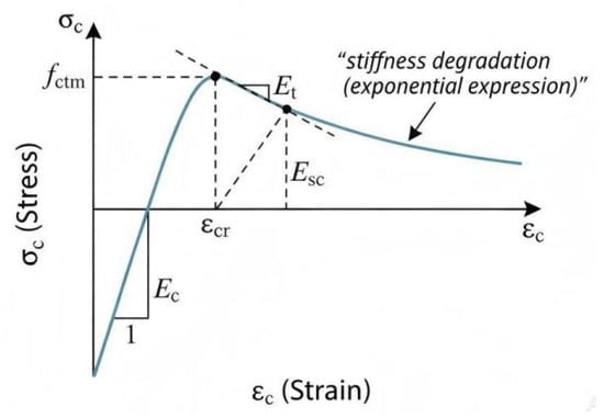
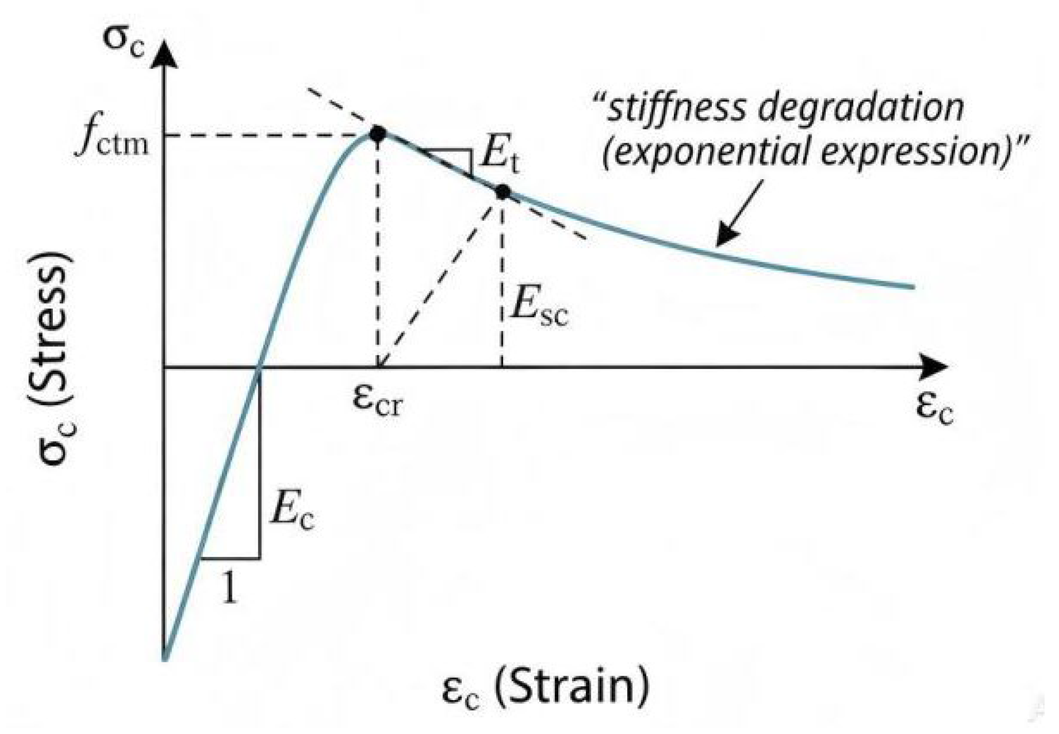
When the concrete is treated as anisotropic material in the event of cracking, due to the very fast rate of decline of this concrete material by tensile softening, the calculation process of the finite element calculation program may result in non-convergence due to the material having an excessive negative stiffness. Therefore, in the design of the actual finite element simulation software program or in writing the design of the development environment, the increment of the tensile softening stress can be calculated by considering the cut-line stiffness method, giving a relatively small negative tangential stiffness method to the cut-line stiffness Et for use in the iterative analysis of the program. As shown in Figure 1, the stiffness and flexibility matrices after cracking are given by the following expressions:
Figure 1.
Constitutive model for concrete.
C11=μEc
2.2. Time-Dependent Analysis
The overall strain ε is the sum of the viscoelastic strain and the stress-independent strain [27]. The uncracked viscoelastic strain is described as follows:
Thus, the increased strain at time tr can be expressed as:
Denoting the average compliance modulus, half of the sum of the flexibility functions at the moments tr and tr−1 can be used as the flexibility function at the intermediate moments, and the expression of the average flexibility function is:
The stress–strain function can be rewritten as:
The increased strain , including creep strain and other, is presented as:
By substituting Equation (27) into Equation (26), the following can be obtained:
2.3. Material Model
The constitutive law of concrete in tension adopts the smeared cracking model introduced by Field and Bischoff [28], in which the stress–strain relation after cracking is formulated in an exponential form:
The regular constitutive law of concrete in compression and the modulus of elasticity follow the provisions in CEB-FIP [29]. The compressive strength fcd, modulus of elasticity Ecd, tensile strength ftd, and ultimate tensile strain εtd of concrete under freezing and thawing conditions take the following rule [30,31]:
The modeling of the steel reinforcements adopts bilinear constitutive relation. With an increase in the corrosion rate, the material properties of prestressing tendons, such as the elastic modulus, ultimate strength, and ultimate strain, decrease to varying degrees. The constitutive model of corroded prestressed steel strands is consistent with that of prestressed steel strands under normal conditions and can also be represented by a bilinear model. However, as the corrosion rate continues to increase, the plasticity of the prestressed steel strands gradually diminishes. When the corrosion rate exceeds 8%, the stress–strain curve degenerates into a single straight line. The stress–strain model of corroded prestressing tendons follows the model introduced by Zeng et al. [32,33] and is given in Equation (34):
In the present study, the corrosion rate is prescribed to represent the degree of corrosion deterioration of the prestressing tendon, and the corresponding deterioration relationships are incorporated into the finite element model. The adopted corrosion treatment primarily considers the degradation of the mechanical properties associated with corrosion. Localized pitting corrosion, corrosion-product expansion, explicit bond-slip deterioration, and corrosion-induced concrete cracking are not separately modeled. These simplifications should be considered when interpreting the influence of corrosion on the long-term structural response.
The environmental deterioration and time-dependent mechanisms are incorporated within a unified time-stepping finite element framework. Freeze–thaw deterioration and corrosion are introduced through the corresponding degradation of material properties, while concrete cracking, creep, shrinkage, and prestressing tendon relaxation continuously affect the stiffness, stress redistribution, deformation, and prestress loss of the beam. Therefore, these mechanisms are considered simultaneously and interact through the evolving material properties and structural response. It should be noted that the present model does not establish an explicit bidirectional physicochemical evolution law between freeze–thaw damage and corrosion; instead, their simultaneous effects are incorporated within the common structural finite element framework.
3. Validation of the FE Model
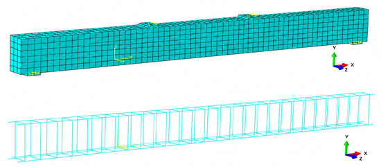
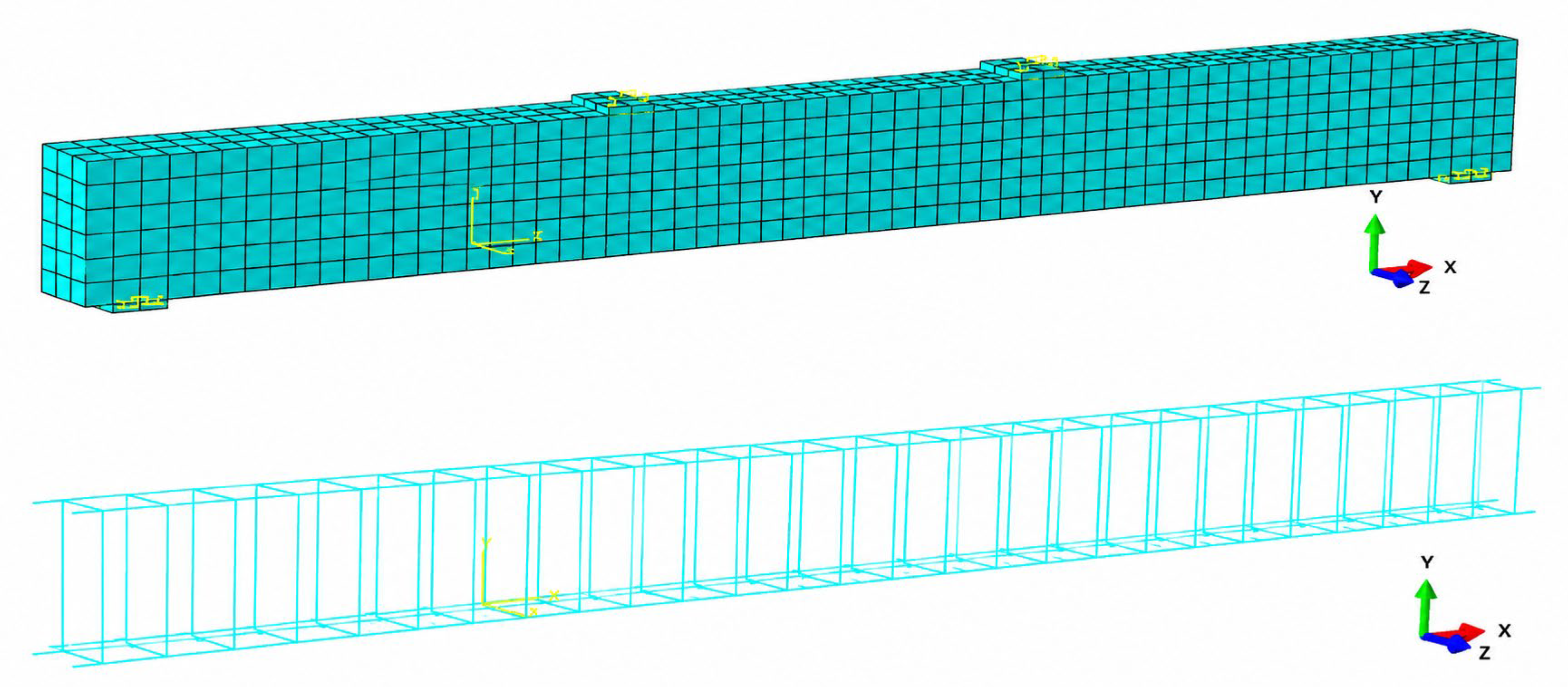
An in-house program written in FORTRAN was developed and integrated into the ABAQUS (commercial finite element package) user subroutine UMAT to implement the proposed material model. This software extension enhances the material library of ABAQUS and improves its ability to simulate concrete creep, shrinkage, corrosion, freeze–thaw, and cracking behaviors. A three-dimensional (3D) modeling approach was adopted to simulate the structural behavior of the prestressed concrete beams. The concrete and insulation layers were modeled using eight-node brick elements (C3D8), with each node having three translational degrees of freedom. Two-node truss elements were employed to represent the steel reinforcement. The reinforcements were considered as being fully embedded within the concrete matrix. Steel bearing plates used in the experimental setup to distribute the concentrated loads were also represented by solid elements. The assembled FE model is shown in Figure 2. The mesh size and time-step interval were selected by considering the geometric characteristics of the beam, the expected stress and deformation gradients, and the computational efficiency required for the 1000-day time-dependent analysis. The adopted discretization provides a reasonable balance between numerical stability, computational cost, and the accuracy required for the present parametric study.
Figure 2.
Assembled FE model.
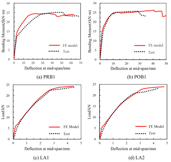
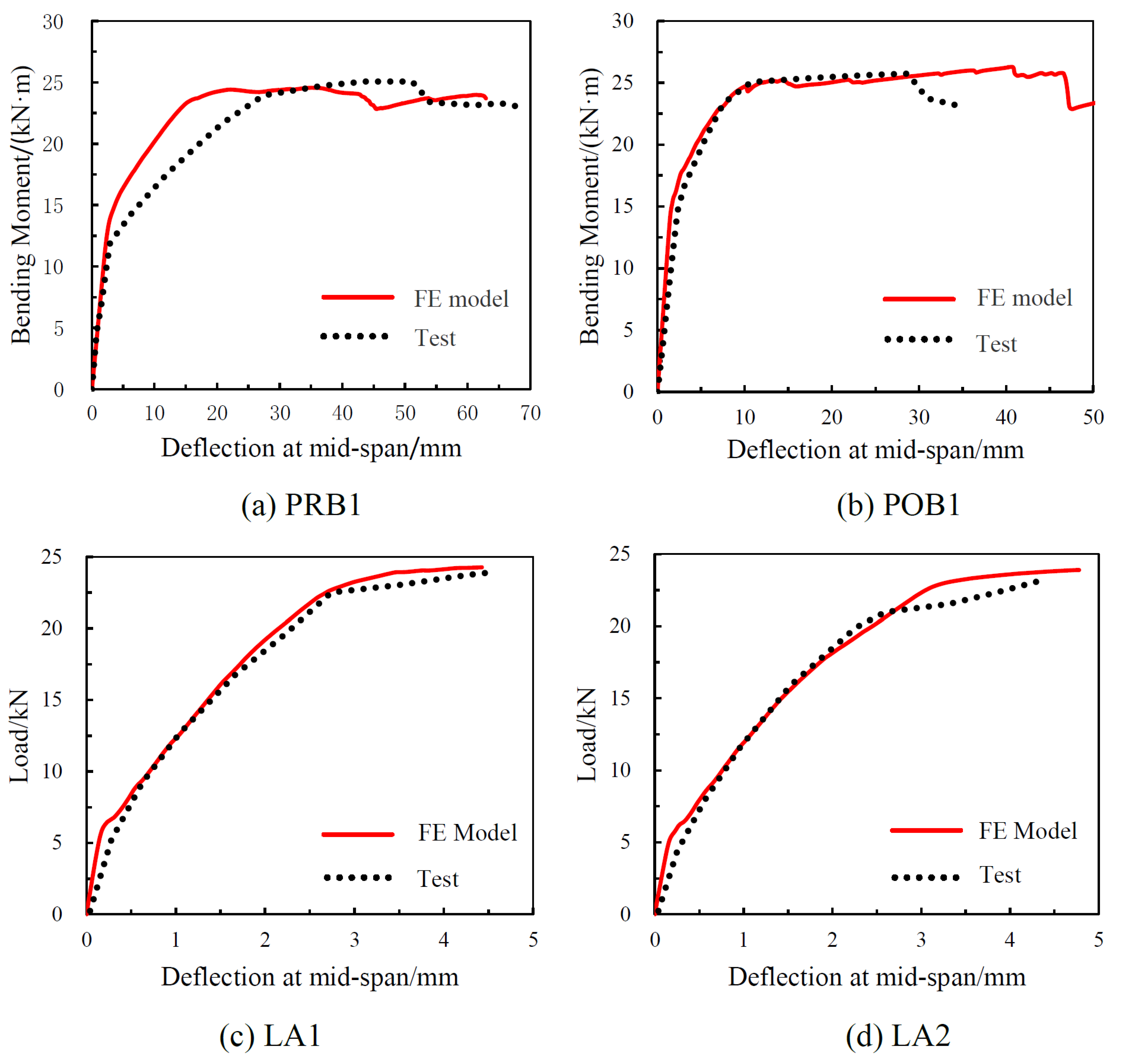
The FE model was first validated against available experimental results representing the major deterioration mechanisms considered in this study. For short-term behavior, experimental results reported by Li et al. [34] for prestressed concrete beams affected by steel corrosion and by Cao et al. [35] for reinforced concrete beams subjected to freeze–thaw cycles were adopted. Four beams were considered, including two prestressed beams affected by steel corrosion (PRB1 and POB1) and two reinforced concrete beams subjected to freeze–thaw cycles (LA1 and LA2). The comparison of load-deflection responses is presented in Figure 3, while the corresponding cracking and ultimate bending moments are summarized in Table 1. The differences between the FE predictions and the experimental results are generally within approximately 10%, indicating that the proposed material and structural formulations can reasonably reproduce the short-term response of deteriorated concrete beams.
Figure 3.
Comparison of short-term load-deflection curves.
Table 1.
Comparison of cracking and failure bending moments.
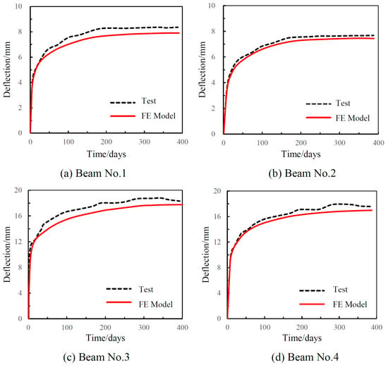
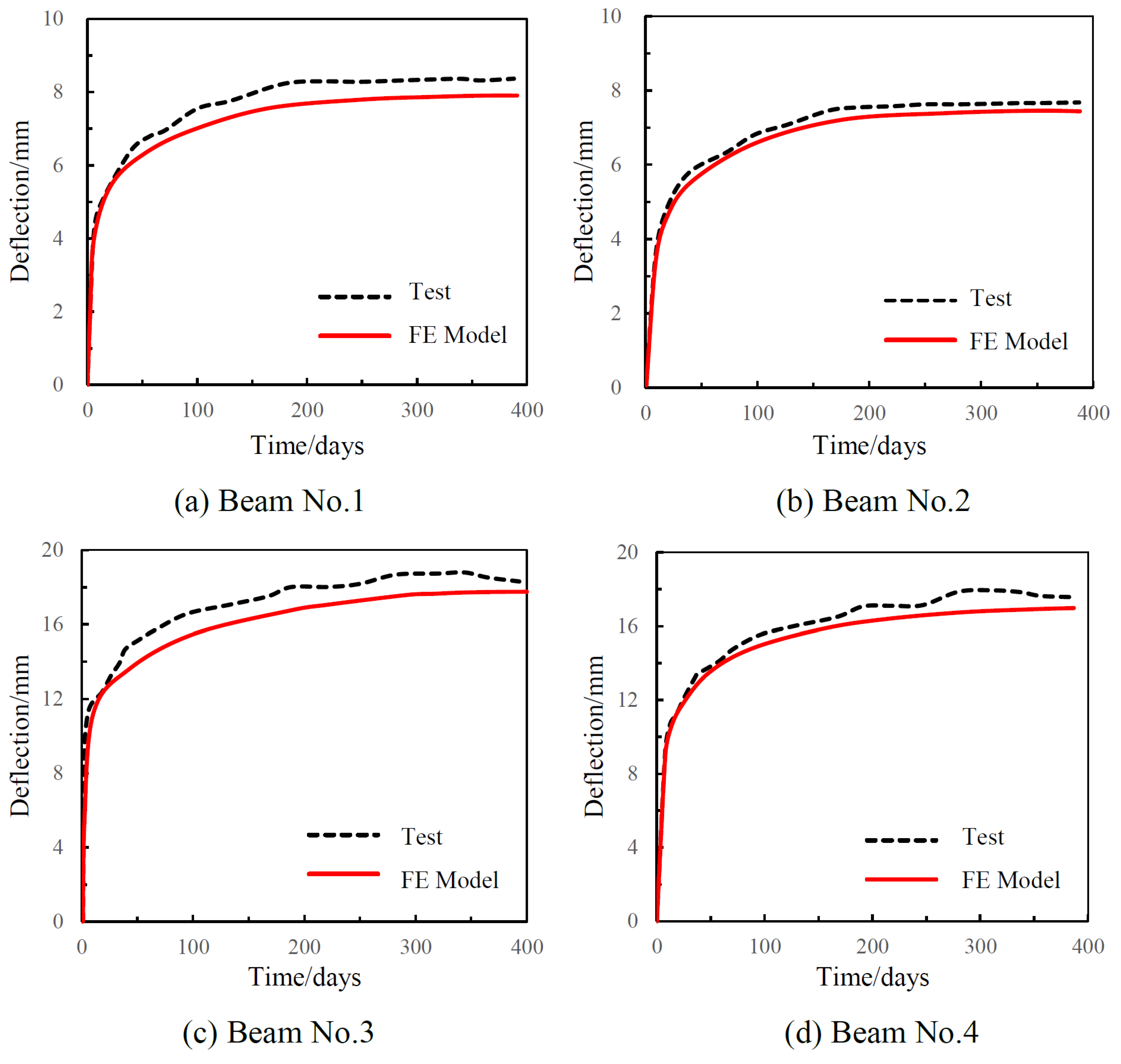
The long-term behavior was further assessed using the experimental results of Cao et al. [35]. Four beams subjected to sustained flexural loading for 400 days were used for comparison. As shown in Figure 4, the predicted mid-span deflections show good agreement with the experimental measurements, and the differences in the 400-day deflections are relatively small. This comparison provides additional evidence that the time-dependent analysis procedure can reasonably reproduce the long-term deformation of concrete beams.
Figure 4.
Comparison of long-term load-deflection curves.
It should be noted that the available experimental datasets do not provide a single test program simultaneously covering prestressing, tendon corrosion, freeze–thaw deterioration, concrete creep and shrinkage, tendon relaxation, and long-term sustained loading. Therefore, the present validation is regarded as a component-based validation of the principal mechanisms incorporated into the proposed framework rather than a direct full-scale validation of all combined mechanisms using one experimental dataset. The subsequent numerical analyses are therefore intended to investigate the combined effects of these mechanisms within the proposed computational framework.
In Figure 3 and Table 1, it can be seen that the load-deflection curves obtained from the test results and numerical calculations show a good agreement. The differences between the bending moments calculated by the FE model and the ones obtained from the tests are generally less than 10%, which could be attributed to scattering of material properties, errors in test setup, and simplified assumptions in the analysis. The comparisons herein give a preliminary verification of the proposed FE model for predicting the short-term behavior prestressed concrete beams after the deterioration of steel corrosion and freeze–thaw cycles.
A comparison with the test results of Cao et al. [35] is also carried out in order to further validate the applicability of the FE on long-term behavior predictions. The results of four beams under sustained flexural actions of 400 days were used for comparisons. The load-deflection curves are shown in Figure 4.
In Figure 4, it can be seen that the time-dependent displacements at the mid-span from the experimental results correlate well with the numerical calculations. The error and fluctuation of the 400-day deflection of the prestressed concrete beam obtained from the numerical analysis and from the tests are very small. The comparisons herein provide a level of validation of the FE model in calculating the long-term behavior of the prestressed concrete beams. In general, based on the comparisons with both short-term and long-term test results, it is considered that the FE model is reliable in predicting the time-dependent behavior of corroded prestressed beams subjected to freeze–thaw deterioration.
It should be noted that the validation presented herein is mechanism-oriented because the available experimental studies do not provide a single dataset covering freeze–thaw deterioration, corrosion, creep, shrinkage, prestressing tendon relaxation, and long-term structural response simultaneously. Therefore, the validation focuses on the capability of the numerical model to reproduce the principal mechanical responses associated with the individual mechanisms, while the subsequent parametric analysis is used to investigate their combined influence on the long-term behavior of prestressed concrete beams.
4. Numerical Example
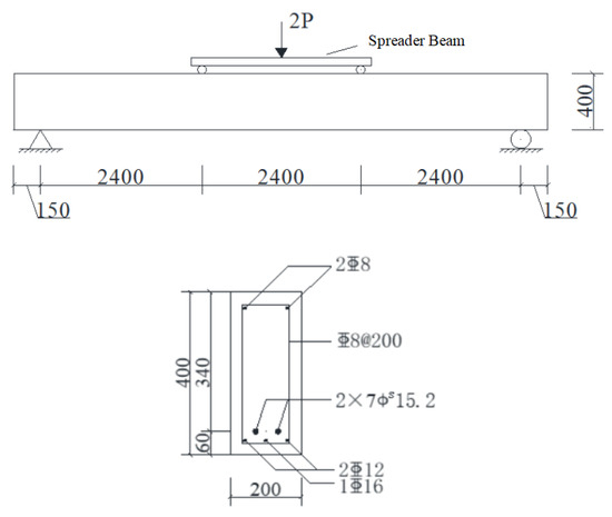
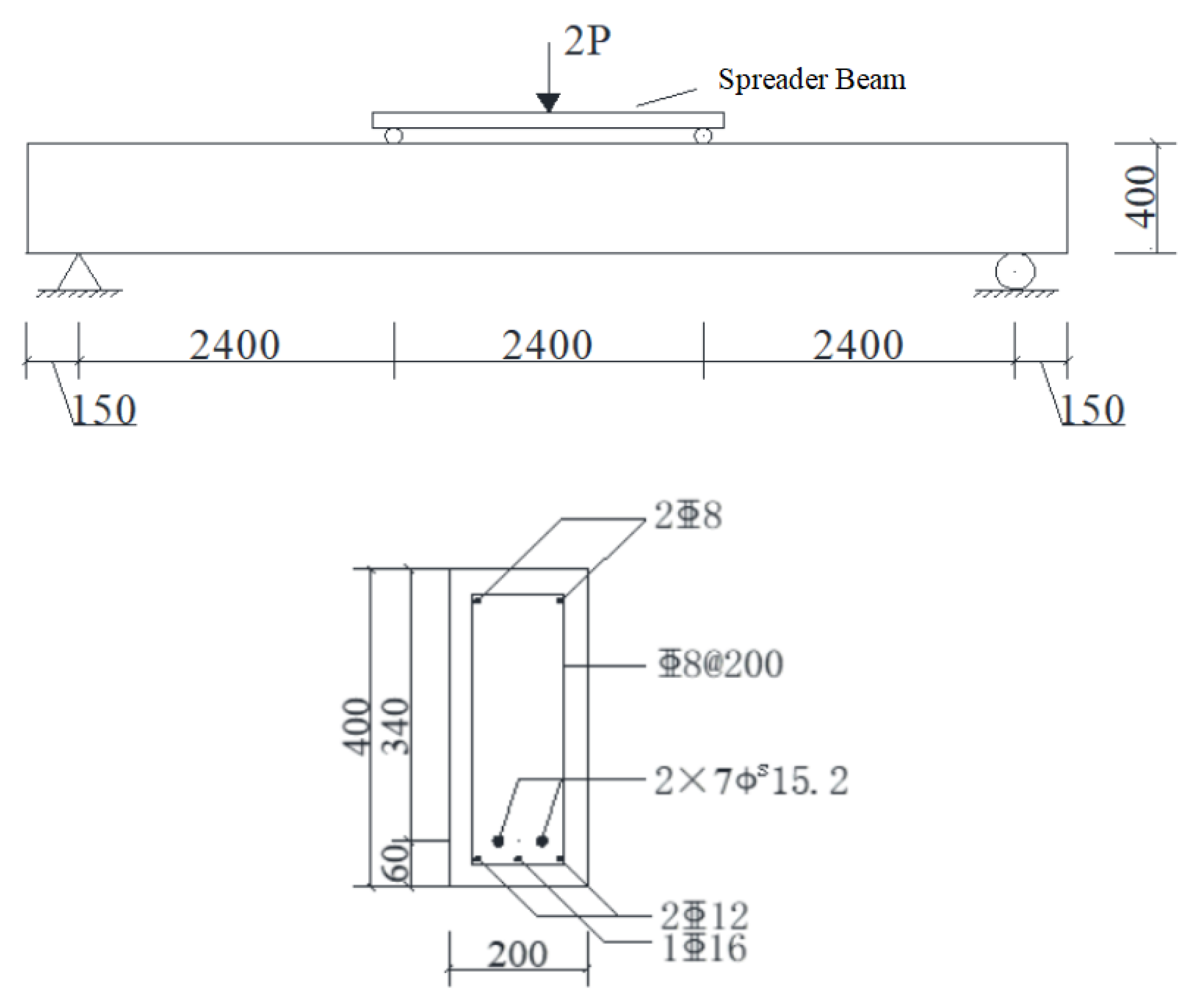
Based on the validations above, a numerical model is developed to furtherly investigate the effects of prestressing loss, concrete creep and shrinkage, freeze and thaw cycles, the corrosion rate, and prestressing levels on the time-dependent behavior of prestressed concrete beams. The cross-section of the beams is 200 mm × 400 mm, and the clear span is 7200 mm. The beams are all simply supported with 40 kN (80 kN in total) vertical loads acting on the locations of one-third span. The reinforcement details of the beams are shown in Figure 5, and the material properties are listed in Table 2.
Figure 5.
Geometry and reinforcing details of the beams.
Table 2.
Material properties of the beams.
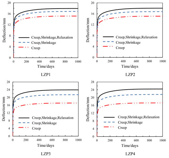
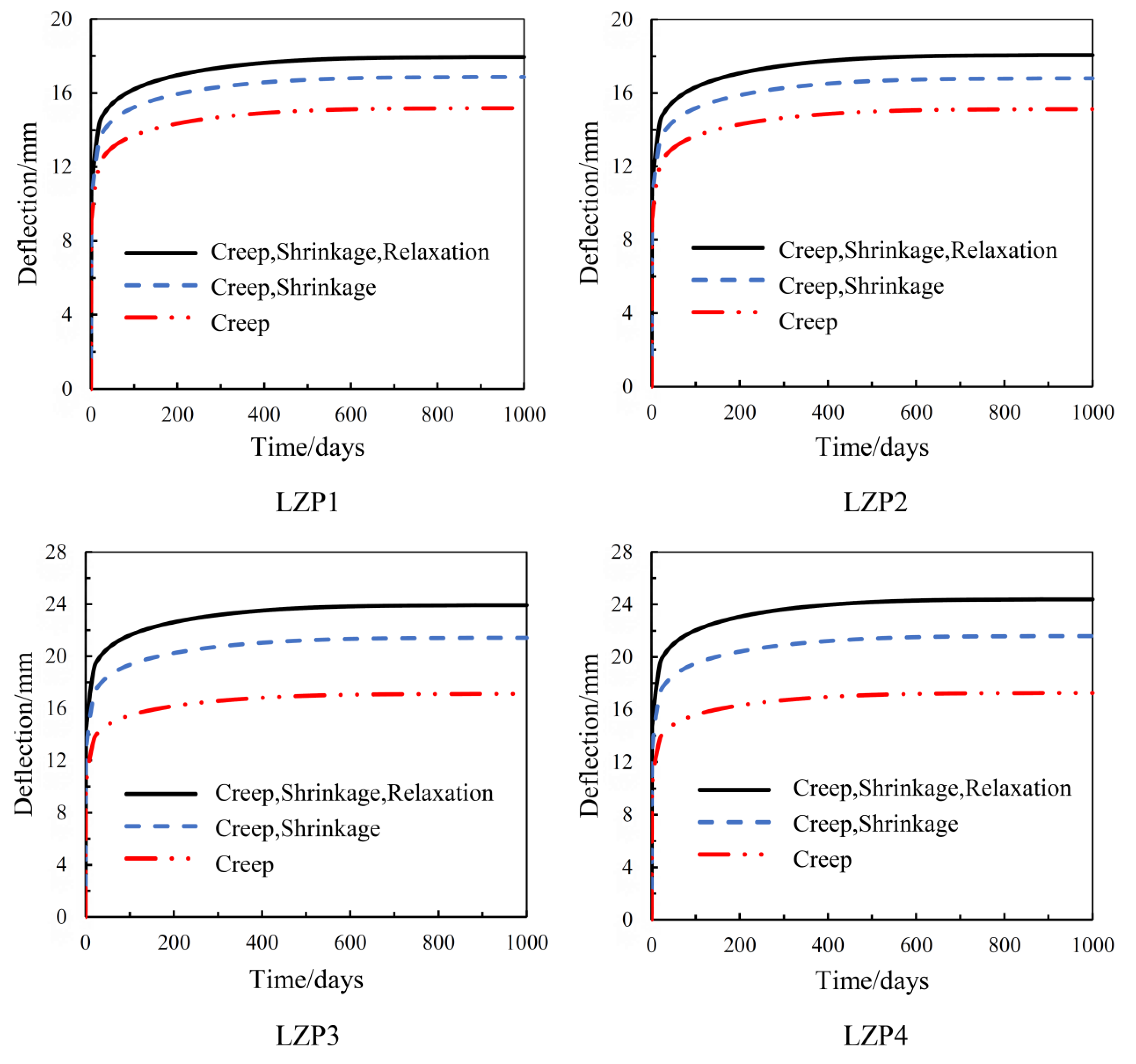
Under long-term loading, the mid-span deflection, prestressing loss, and concrete strain of prestressed concrete beams change with time. Since these long-term properties are affected by concrete creep, shrinkage, and prestressing relaxation, in order to investigate the degree and law of the influence of these factors on the long-term time-varying properties, four groups of prestressed concrete beams under different conditions were continuously loaded for 1000 days The parameters of prestressed concrete beams are shown in Table 3. The mid-span deflection versus time is shown in Figure 6.
Table 3.
Parameters of the prestressed beams under long-term loading.
Figure 6.
Mid-span deflections versus time of the beams.
In Figure 6 and Table 4, it can be seen that the change of time-dependent displacement of ordinary prestressed concrete beams and corroded prestressed concrete beams subjected to freeze–thaw cycles are very similar. The mid-span deflections with time of the four types of prestressed concrete beams affected by concrete shrinkage, creep, and prestressing tendon relaxation at the same time show that the mid-span deflection of prestressed concrete beams at 100 days of loading already accounts for more than 80% of the total deflection at 1000 days of loading, and after 100 days of loading, the growth rate of deflection of prestressed concrete beams decreases. The deformation curve of the prestressed concrete beam tends to be parallel to the time axis at the later stage, and the long-term deformation tends to converge, which indicates that the long-term deformation of the prestressed concrete beam basically approached to a certain value at 3 years of sustained load, which is consistent with the actual situation. In addition, the 1000-day long-term deflections of LZP1~LZP4 increased by 6.2%, 7.3%, 11.5%, and 12.7%, respectively, when the factors of concrete creep, shrinkage, and prestressing tendon relaxation were considered comprehensively compared with those of concrete creep and shrinkage only; the 1000-day long-term deflections of LZP1~LZP4 increased by 6.2%, 7.3%, 11.5%, and 12.7%, respectively, when the factors of concrete creep, shrinkage, and prestressing tendon relaxation were considered comprehensively compared with those of concrete creep only. The long-term deflection at 1000 days increased by 18.0%, 19.1%, 39.0%, and 42.1% for LZP1~LZP4, respectively. This indicates that both prestressing tendon relaxation and concrete shrinkage have a greater effect on the long-term deflection under the same conditions. The effects of any of the three factors—concrete creep, shrinkage, and prestressing tendon relaxation—cannot be neglected in the process of long-term force performance analysis of prestressed concrete beams.
Table 4.
Change in mid-span deflection of the beams.
By comparing LZP1 with LZP3, it is found that the 1000-day long-term deflection of ordinary prestressed concrete beams is about 1.89 times of the loaded instantaneous deflection, while the 1000-day long-term deflection of prestressed concrete beams subjected to freeze–thaw cycles is 2.08 times of the loaded instantaneous deflection. This indicates that in prestressed concrete beams, the freeze–thaw cycling factors make the effects of concrete creep, shrinkage, and prestressing tendon relaxation on the long-term deflection of prestressed concrete beams increase, and it can be predicted that the final stabilization time of the structural deflection under the influence of freeze–thaw cycling is going to occur somewhat longer in actual projects.
The comparison of LZP2, LZP3, and LZP1 reveals that the 1000-day long-term deflection of corroded prestressed concrete beams increases only 0.6% compared with that of ordinary prestressed concrete beams when considering concrete creep, shrinkage, and prestressing tendon relaxation, and the 1000-day long-term deflection of prestressed concrete beams under the effect of freeze–thaw cycling increases 33% compared with that of ordinary prestressed concrete beams, indicating that the effect of freeze–thaw cycling is significantly higher than the effect of corrosion on the long-term deflection of prestressed concrete beams.
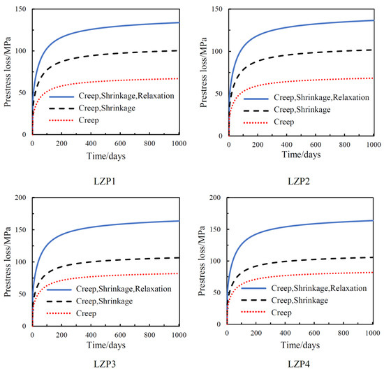
The prestress loss values of prestressing concrete prestressing tendons were recorded for a long period of 1000 days, and the prestress loss time relationship curves are shown in Figure 7. In Figure 7, it is obvious that the long-term prestress loss of prestressed concrete beams considering concrete creep shrinkage and prestressing tendon relaxation is significantly greater than the long-term prestress loss of prestressed concrete beams considering only concrete creep and shrinkage and much greater than the long-term prestress loss of beams considering only concrete creep; taking LZP1 as an example,, the long-term prestress loss for the beam considering only creep is 75% of the long-term prestress loss for the beam considering creep and shrinkage and is 55% of the long-term prestress loss for the beam considering creep, shrinkage, and stress relaxation. This also confirms the numerical simulation method of prestressing tendon relaxation described in the previous chapter, where the value of prestressing loss is importantly related to the shrinkage of the concrete in addition to its own relaxation effect.
Figure 7.
Time-dependent loss of prestresses.
The comparison between LZP1 and LZP4 shows that the effect of prestressing tendon relaxation on prestressing loss is greater in LZP4 than in LZP1, and the ratio of prestressing loss due to creep shrinkage to prestressing loss due to creep shrinkage relaxation is reduced from 76.3% in LZP1 to 62.1% in LZP4. This indicates that the effect of freeze–thaw cycling and corrosion increases the effect of prestressing tendon relaxation on long-term prestressing loss.
Comparing LZP1 with LZP3 under the combined consideration of creep shrinkage and prestressing tendon relaxation, it is found that the prestress loss value of prestressed concrete beams under freeze–thaw cycling is about 28.4% higher than that of prestressed beams of ordinary concrete beams; comparing LZP1 with LZP2, the change in the prestress loss value is smaller for both of them, which is only about 1%. The main reason is due to the rapid decrease in the elastic modulus and compressive strength of concrete under the action of freeze–thaw cycles and the increase in the shrinkage strain of concrete and the coordinated deformation of displacement between the prestressing tendons. The corrosion of prestressing tendons has little effect on their own modulus of elasticity and, therefore, little effect on the loss of prestressing.
5. Parametric Studies
In addition to concrete creep, shrinkage, and prestressing tendon relaxation, this study also investigates the effects of concrete strength, the number of freeze–thaw cycles, the corrosion rate, and the prestress level on the long-term performance of prestressed concrete beams.
5.1. Effect of Concrete Strength
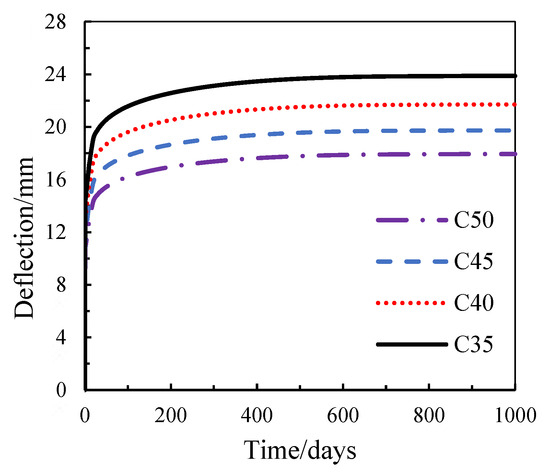
This section investigates the long-term mechanical performance of corroded prestressed concrete beams with four different concrete strength grades under freeze–thaw cycling. The parameter design of the four groups of prestressed concrete beams is presented in Table 5. The mid-span deflection time-history responses of the prestressed concrete beams are presented in Figure 8 and Table 6.
Table 5.
Modeling of prestressed concrete beams with varying concrete strength.
Figure 8.
Effect of concrete strength on beam displacement.
Table 6.
Short-term and long-term deflection with varying concrete strengths.
As shown in Figure 8 and Table 6, both the short-term and long-term deflections of the prestressed concrete beams decrease with increasing concrete strength. The 1000-day long-term deflection decreases from 24.1 mm for the C35 beam to 18.0 mm for the C50 beam. The long-term deflection of the C35 beam is therefore 33.9%, 22.3%, and 11.1% higher than that of the C50, C45, and C40 beams, respectively. The corresponding long-term additional deflections are 9.9, 8.8, 7.9, and 7.3 mm for C35, C40, C45, and C50, respectively. The difference in long-term additional deflection between adjacent strength grades decreases progressively from 1.1 mm between C35 and C40 to 0.6 mm between C45 and C50. These results indicate that higher concrete strength provides an increasingly effective restraint against long-term deformation.
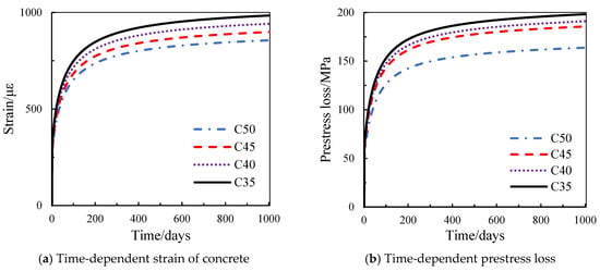
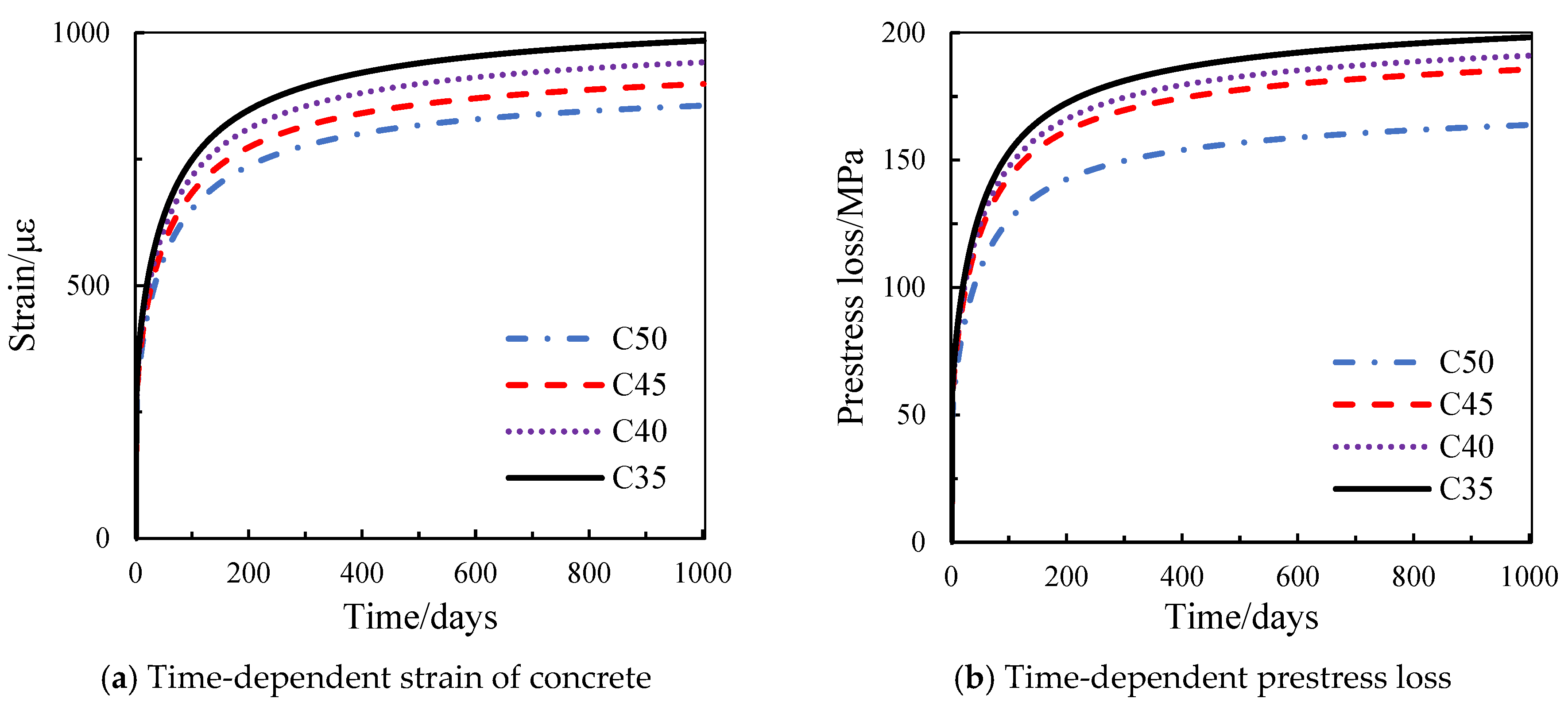
Figure 9 and Table 7 further show that the long-term compressive strain at the mid-span compression zone decreases with increasing concrete strength. The ultimate compressive edge strain of the C35 beam is 4.6%, 14.0%, and 25.9% higher than that of the C40, C45, and C50 beams, respectively. The corresponding strain increments decrease as the concrete strength increases, which is consistent with the reduced creep and shrinkage deformation of higher-strength concrete.
Figure 9.
Effect of concrete strength on concrete strain and prestress loss.
Table 7.
Strain and prestress loss of prestressed concrete beams.
Prestress loss also decreases with increasing concrete strength. The long-term prestress losses of the C35, C40, C45, and C50 beams are 198.2, 192.9, 185.6, and 163.8 MPa, respectively. The prestress loss of the C35 beam is 2.7%, 6.8%, and 21.0% higher than that of the C40, C45, and C50 beams, respectively. These results indicate that increasing concrete strength can effectively reduce both long-term deformation and prestress loss.
5.2. Effect of Freeze–Thaw Cycling
This section investigates the long-term mechanical performance of corroded prestressed concrete beams subjected to four different numbers of freeze–thaw cycles. The parameter design of the four groups of prestressed concrete beams is presented in Table 8. The mid-span displacement time-history responses of the prestressed concrete beams are presented in Figure 10 and Table 9.
Table 8.
Modeling of prestressed concrete beams with varying freeze–thaw cycles.
Figure 10.
Effect of freeze–thaw cycling on beam deflections.
Table 9.
Short-term and long-term deflection with different freeze–thaw cycles.
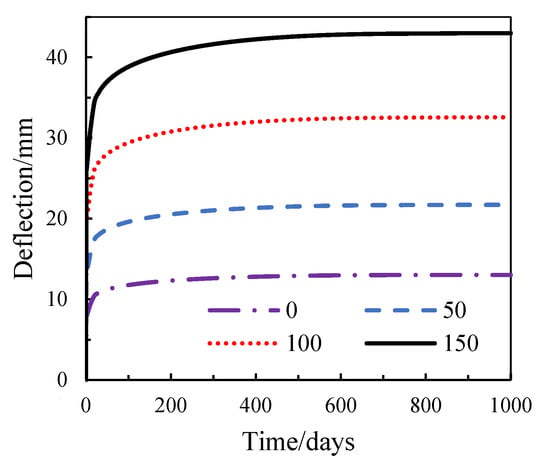
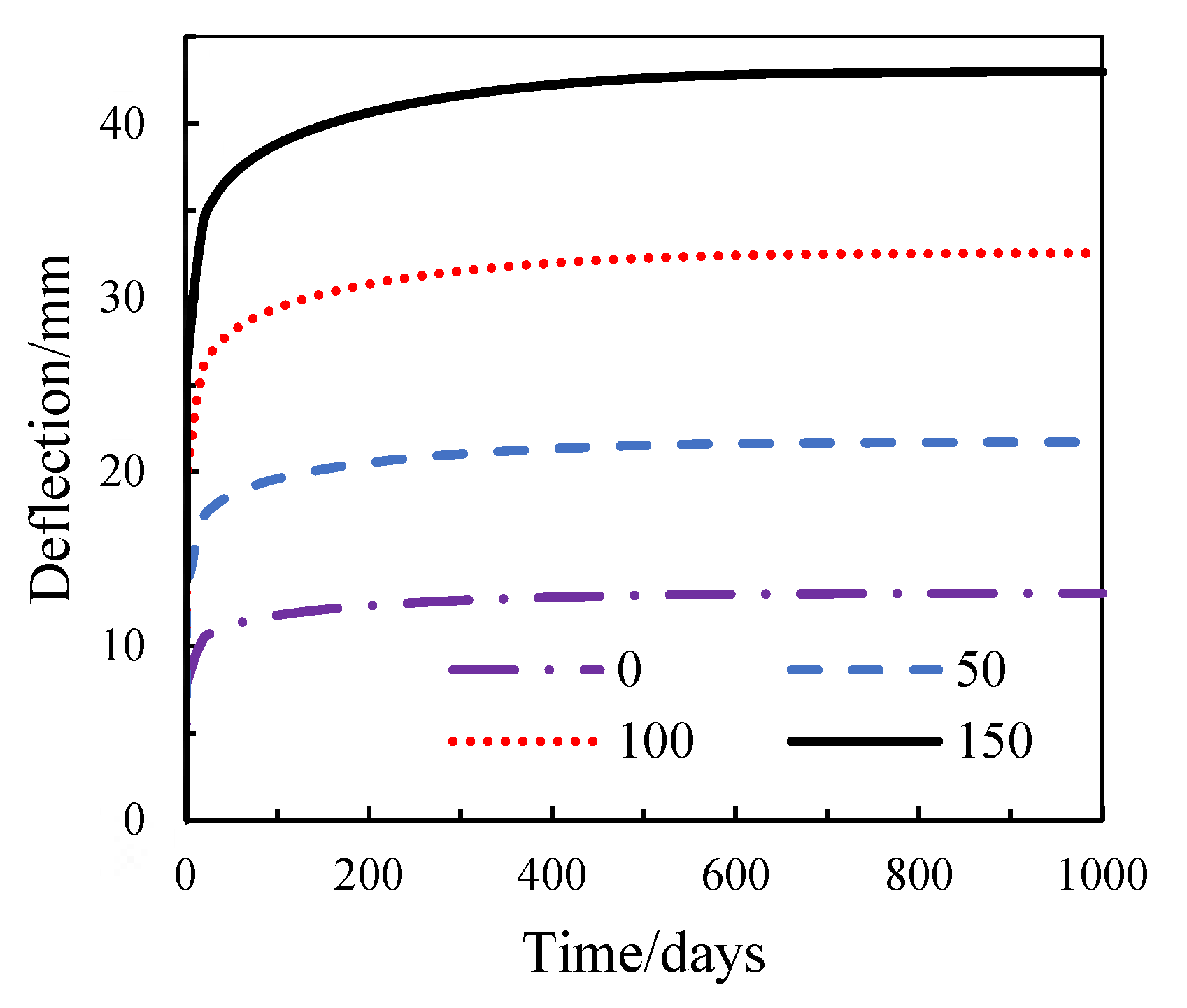
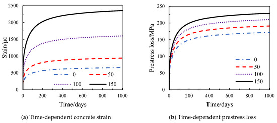
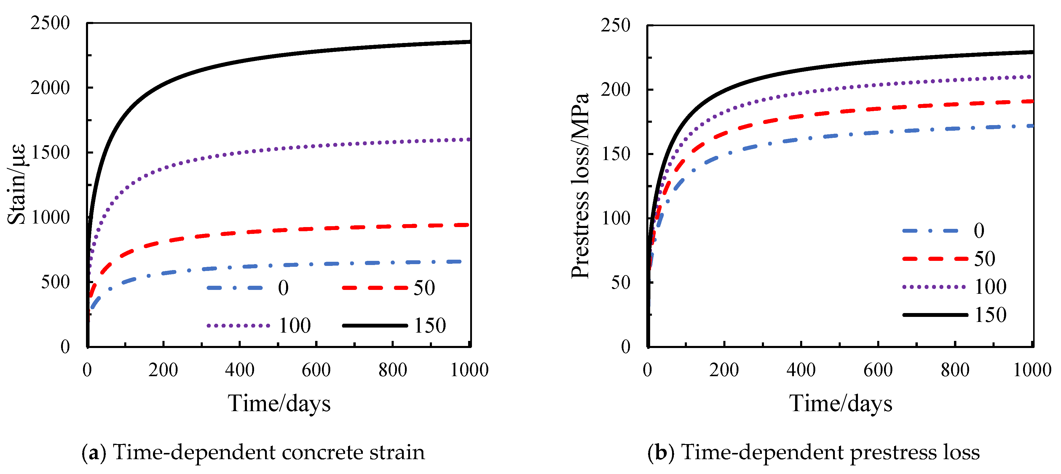
As shown in Figure 10 and Table 9, both the short-term and long-term deflections increase with the number of freeze–thaw cycles. The 1000-day long-term deflection increases from 13.0 mm at 0 cycles to 21.7 mm, 32.5 mm, and 42.9 mm at 50, 100, and 150 cycles, respectively. The deflection at 150 cycles is 32.0%, 97.7%, and 230.0% higher than that at 100, 50, and 0 cycles, respectively. The corresponding long-term additional deflections are 5.1, 8.8, 13.3, and 20.9 mm. The additional deflections at 0, 50, and 100 cycles correspond to 24.4%, 42.1%, and 63.6% of the value at 150 cycles, respectively. Furthermore, for each additional 50 freeze–thaw cycles, the increase in long-term additional deflection becomes progressively larger. Specifically, the increase is 3.7 mm from 0 to 50 cycles, 4.5 mm from 50 to 100 cycles, and 7.6 mm from 100 to 150 cycles. This progressive increase indicates that freeze–thaw deterioration has a pronounced influence on the time-dependent deformation of the prestressed concrete beams.
As shown in Figure 11 and Table 10, the long-term compressive strain also increases substantially with the number of freeze–thaw cycles. The ultimate compressive strains are 199, 238, 552, and 870 με for 0, 50, 100, and 150 cycles, respectively. The strain at 150 cycles is approximately 1.58, 3.66, and 4.37 times that at 100, 50, and 0 cycles, respectively. The corresponding additional strain increases from 460 με at 0 cycles to 1683 με at 150 cycles. The long-term prestress loss increases from 171.0 MPa at 0 cycles to 229.1 MPa at 150 cycles. The prestress loss at 150 cycles is approximately 9.1%, 20.0%, and 34.0% higher than that at 100, 50, and 0 cycles, respectively. These results demonstrate that freeze–thaw deterioration substantially amplifies the long-term deformation, concrete compressive strain, and prestress loss of the beams.
Figure 11.
Effect of freeze–thaw cycling on concrete strain and prestress loss.
Table 10.
Prestressed beam strain and prestress loss.
5.3. Effect of Corrosion Rate
This section investigates the long-term mechanical performance of prestressed concrete beams with different corrosion rates under freeze–thaw cycling. The parameter design of the four groups of prestressed concrete beams is presented in Table 11. The mid-span displacement time-history responses of the prestressed concrete beams are presented in Figure 12 and Table 12.
Table 11.
Modeling of Prestressed Beam with Different Corrosion Rates.
Figure 12.
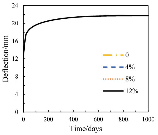
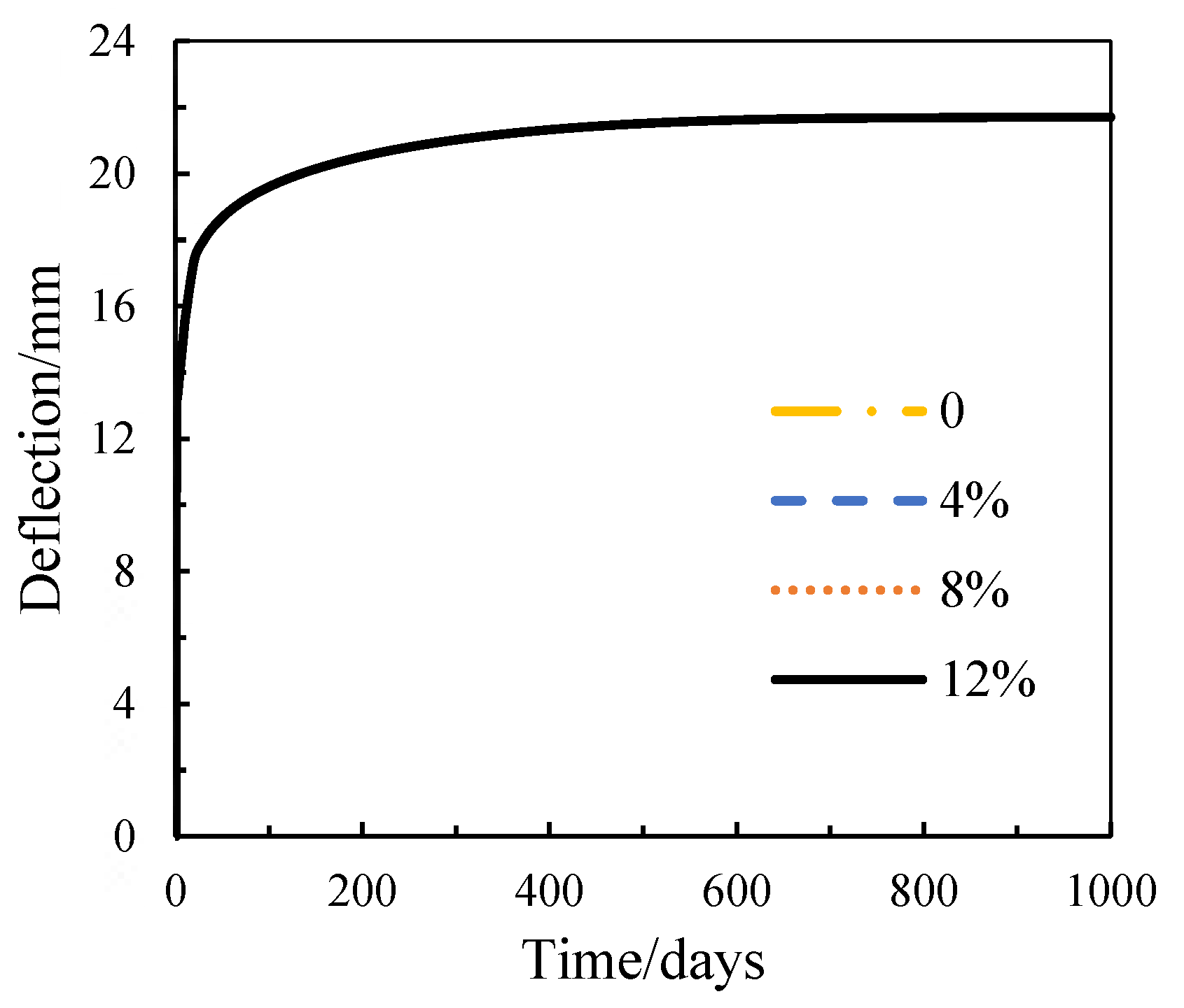
Effect of corrosion rate on beam deflection.
Table 12.
Short-term and long-term deflection under different corrosion rate.
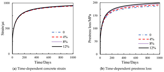
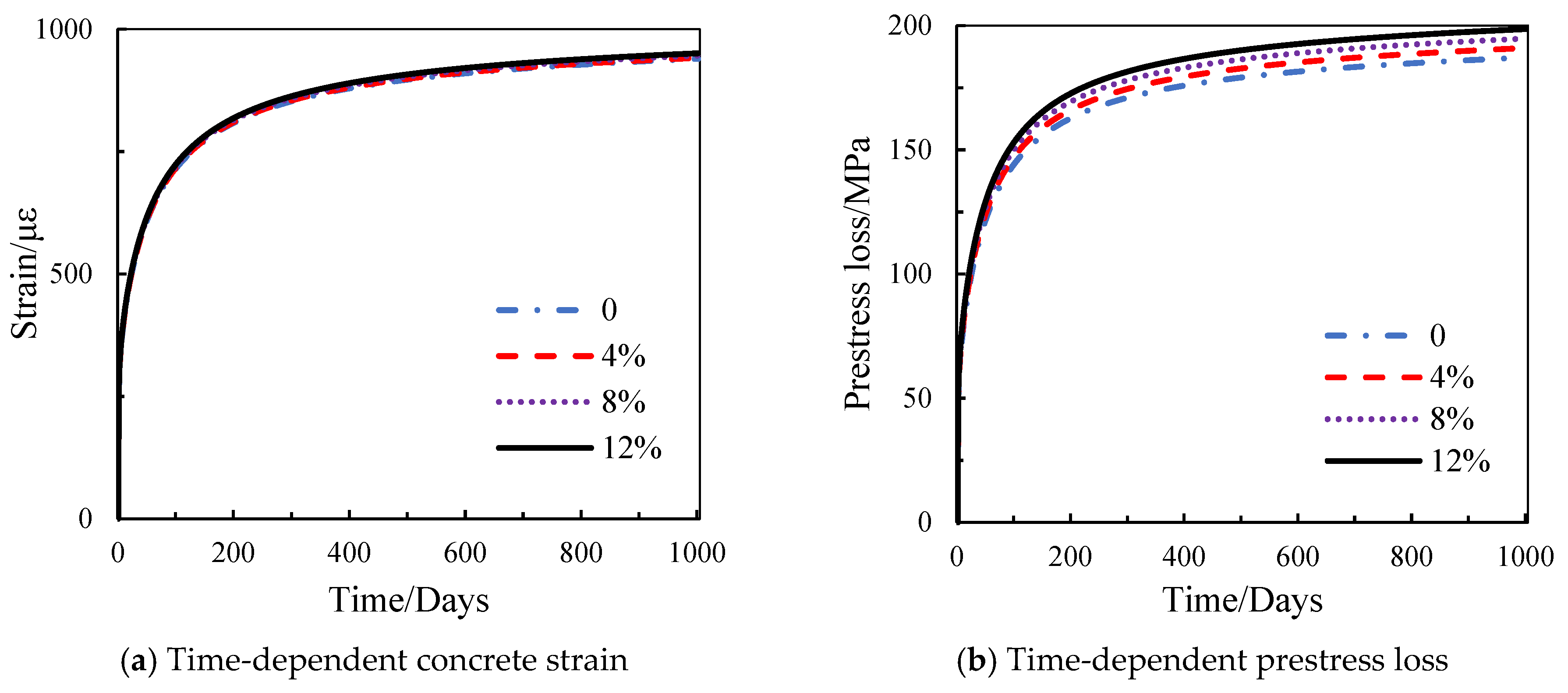
As shown in Figure 12 and Table 12, the long-term deformation trends of the prestressed concrete beams with tendon corrosion rates of 0%, 4%, 8%, and 12% are generally similar. The short-term deflections are 12.8, 12.9, 12.9, and 13.0 mm, while the corresponding 1000-day long-term deflections are 21.6, 21.7, 21.7, and 21.8 mm, respectively. The ratio of long-term deflection to short-term deflection remains approximately 1.69 for all cases. Even at a corrosion rate of 12%, the long-term deflection is only 0.2 mm higher than that of the uncorroded beam. This indicates that within the investigated corrosion range and under the considered freeze–thaw and loading conditions, tendon corrosion has a limited influence on the global long-term deflection.
However, the influence of tendon corrosion on prestress loss is more noticeable. As shown in Figure 13 and Table 13, the long-term prestress losses are 188.2, 190.9, 192.9, and 198.0 MPa for corrosion rates of 0%, 4%, 8%, and 12%, respectively. The prestress loss increases by 9.8 MPa from the uncorroded case to the 12% corrosion case. This indicates that the global beam deflection is relatively insensitive to tendon corrosion within the investigated range, whereas the internal prestressing state is more sensitive to corrosion-induced deterioration.
Figure 13.
Effect of corrosion rate on concrete strain and prestress loss.
Table 13.
Prestressed beam strain and prestress loss with different corrosion rates.
As shown in Figure 13 and Table 13, the mid-span compressive strain development of beams with prestressing tendon corrosion rates of 0%, 4%, 8%, and 12% follows a similar trend, which corresponds to the observed deflection behavior. The long-term deformation of the top concrete is nearly identical, showing minimal variation. Prestress loss slightly increases with higher corrosion rates; the ultimate prestress loss of the beam with 0% corrosion is only 9.8 MPa less than that of the beam with a 12% corrosion rate.
5.4. Effect of Prestressing Force
This section investigates the long-term mechanical performance of corroded prestressed concrete beams under freeze–thaw cycling with four different prestress levels. The parameter design of the four groups of prestressed concrete beams is presented in Table 14, and their mid-span displacement time-history responses are shown in Figure 14 and Table 15.
Table 14.
Modeling of prestressed beam using different prestresses.
Figure 14.
Effect of prestressing level on beam deflection.
Table 15.
Short-term and long-term deflection using different prestresses.
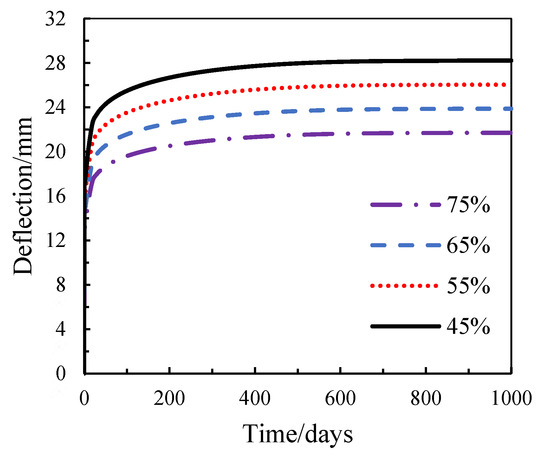
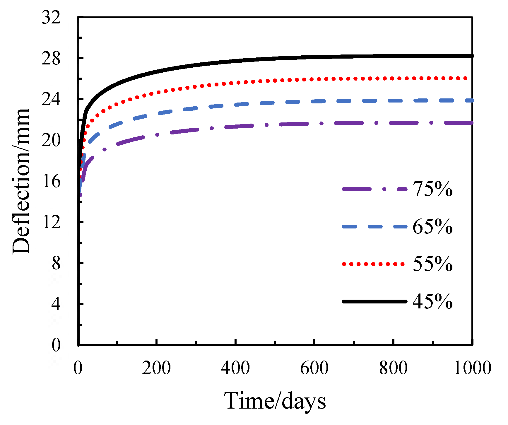
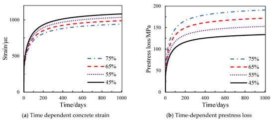
As shown in Figure 14 and Table 15, increasing the applied prestress level reduces the short-term deflection, long-term deformation, and long-term additional deflection of prestressed concrete beams. Specifically, the beam with a prestress level of 0.45 fptk exhibits approximately 29.5% higher long-term additional deflection compared to the beam with a prestress level of 0.75 fptk. This indicates that higher prestress can partially counteract the long-term deformation caused by concrete shrinkage and creep. Figure 15 and Table 16 illustrate the effects of the prestress level on beam strain and prestress loss.
Figure 15.
Effect of prestressing level on concrete strain and prestress loss.
Table 16.
Concrete strain and prestress loss with different prestresses.
As shown in Figure 15 and Table 16, prestress loss is significantly influenced by the prestress level. The prestress loss of the beam with a prestress level of 0.75 fptk is 1.12, 1.25, and 1.43 times that of beams with prestress levels of 0.65, 0.55, and 0.45 fptk, respectively. The long-term compressive strain at the mid-span edge decreases with an increasing prestress level. Specifically, the ultimate compressive strain of the beam with 0.75 fptk is 47, 97, and 151 με lower than that of beams with 0.65, 0.55, and 0.45 fptk, respectively. Moreover, the strain increment (additional strain) decreases from 771 με to 703 με as the prestress level increases.
Overall, the parametric results indicate that the investigated parameters have different levels of influence on the long-term behavior of prestressed concrete beams. Within the parameter ranges considered, freeze–thaw cycles have the most pronounced effect on long-term deflection, followed by the concrete strength and prestress level, whereas corrosion has a relatively minor effect on this response. The combined cases further indicate that the effects of freeze–thaw deterioration and corrosion on long-term deflection are approximately additive, with no significant additional interaction observed within the investigated parameter range. These comparisons provide a qualitative sensitivity assessment of the investigated parameters and highlight the dominant role of freeze–thaw deterioration in the long-term deformation response.
However, several limitations should be noted when interpreting the present numerical results. The corrosion process is represented by a prescribed corrosion rate and corresponding material deterioration relationships, while freeze–thaw damage is introduced through prescribed changes in concrete mechanical properties. Therefore, the present model does not explicitly reproduce localized corrosion, corrosion-product expansion, detailed bond deterioration, or the complex microstructural evolution of concrete under freeze–thaw exposure. In addition, no explicit bidirectional physicochemical evolution law between corrosion and freeze–thaw damage is considered. These limitations may affect the predicted structural response under highly localized or severe deterioration conditions and will be addressed in future work.
6. Conclusions
This study developed an integrated three-dimensional finite element framework for investigating the short-term and long-term mechanical behavior of prestressed concrete beams subjected to sustained loading and combined freeze–thaw and corrosion deterioration. The framework incorporates concrete smeared cracking and tension stiffening, creep and shrinkage, prestressing tendon relaxation, freeze–thaw-induced degradation of concrete properties, and corrosion-induced deterioration of reinforcing steel and prestressing tendons. Based on the numerical analyses, the following conclusions can be drawn:
The proposed FE model provides reasonable predictions of the available experimental results for short-term behavior under corrosion and freeze–thaw deterioration, as well as long-term deformation under sustained loading. The validation results indicate that the principal material deterioration and time-dependent mechanisms incorporated in the model can reasonably reproduce the observed structural responses. However, because no single experimental dataset simultaneously covers all the deterioration mechanisms considered in this study, the present validation should be regarded as a component-based validation.
Concrete strength has a clear influence on long-term deformation. Increasing the concrete strength from C35 to C50 reduces the 1000-day long-term deflection from 24.1 mm to 18.0 mm. The corresponding long-term prestress loss decreases from 198.2 MPa to 163.8 MPa. The reduction in creep and shrinkage deformation associated with higher concrete strength contributes to the improved long-term performance.
Freeze–thaw deterioration has the most pronounced influence among the investigated environmental parameters. The 1000-day long-term deflection increases from 13.0 mm at 0 freeze–thaw cycles to 42.9 mm at 150 cycles, corresponding to an increase of approximately 230%. The long-term prestress loss also increases from 171.0 MPa to 229.1 MPa. These results indicate that progressive freeze–thaw deterioration can substantially amplify the time-dependent deformation and prestress loss of prestressed concrete beams.
Within the investigated corrosion range and under the adopted corrosion modeling assumptions, corrosion has a relatively minor influence on long-term deflection. Increasing the corrosion rate from 0% to 12% increases the 1000-day deflection only from 21.6 mm to 21.8 mm. Nevertheless, the corresponding long-term prestress loss increases from 188.2 MPa to 198.0 MPa, indicating that corrosion has a more noticeable influence on the internal prestressing state than on global beam deflection under the investigated conditions.
Increasing the prestress level effectively restrains beam sagging and long-term deformation. The long-term additional deflection decreases from 11.4 mm at 0.45 fptk to 8.8 mm at 0.75 fptk. However, a higher initial prestress level is accompanied by greater prestress loss, indicating a trade-off between deformation control and prestress-loss development.
Overall, the results demonstrate that the long-term behavior of prestressed concrete beams is governed by the combined effects of environmental deterioration and time-dependent mechanical mechanisms. Within the investigated parameter ranges, freeze–thaw deterioration and concrete creep and shrinkage have a substantially greater influence on global long-term deformation than tendon corrosion. The proposed integrated framework can therefore be used as a numerical tool for evaluating the time-dependent response of prestressed concrete beams under combined environmental and mechanical deterioration.
Author Contributions
Q.H. contributed to the conceptualization, methodology design, writing—original draft preparation, and the acquisition of funding. Y.H. contributed to supervision, project administration, investigation, and the provision of resources. L.G. contributed to investigation, software development, data curation, and formal analysis. All authors have read and agreed to the published version of the manuscript.
Funding
The work reported in this paper has been undertaken with the financial support of the Nantong Science and Technology Bureau through a Social and Livelihood Science and Technology Program (Grant No. MSZ2024079) and the Jiangsu Higher Education Institutions Basic Research Project (Grant No. 25KJD560011).
Institutional Review Board Statement
Not applicable. No human or animal subjects were involved in this study.
Informed Consent Statement
Not applicable. This study does not contain any individual person’s data; therefore, consent for publication was not required.
Data Availability Statement
The data/datasets used and/or analyzed during the current study are available from the corresponding author on reasonable request.
Conflicts of Interest
The authors declare no conflicts of interest.
References
- Schupack, M. A survey of the durablity performance of post-tensioning tendons. ACI J. Proc. 1978, 75, 501–510. [Google Scholar] [CrossRef] [Scilit]
- Collins, R.A. The destruction of concrete by frost. J. Ice 2015, 23, 29–41. [Google Scholar] [CrossRef] [Scilit]
- Powers, T.C. A working hypothesis for further studies of frost resistance of concrete. ACI J. Proc. 1945, 16, 245–272. [Google Scholar] [CrossRef] [Scilit]
- Powers, T.C. Air requirement of frost-resistant concrete. Highw. Res. Board Proc. 1949, 29, 184–202. [Google Scholar]
- Guo, T.; Chen, Z.; Lu, S.; Yao, R. Monitoring and analysis of long-term prestress losses in post-tensioned concrete beams. Measurement 2018, 122, 573–581. [Google Scholar] [CrossRef] [Scilit]
- Abdel-Jaber, H.; Branko, G. Monitoring of long-term prestress losses in prestressed concrete structures using fiber optic sensors. Struct. Health Monit. 2019, 18, 254–269. [Google Scholar] [CrossRef] [Scilit]
- Liu, Y.; Fan, Y.; Yu, J.; Li, Q. Flexural behavior test of corroded prestressed concrete beams under chloride environment. Acta Mater. Compos. Sin. 2020, 37, 707–715. (In Chinese) [Google Scholar] [CrossRef]
- Ting, S.C.; Nowak, A.S. Effect of Tendon-Area Loss on Flexural Behavior of P/C Beams. J. Struct. Eng. 1991, 117, 1127–1143. [Google Scholar] [CrossRef] [Scilit]
- Liu, R.; Lu, Z.; Li, L. Design of Reinforcement in Prestressed Beams with Openings. Adv. Struct. Eng. 2000, 3, 41–48. [Google Scholar] [CrossRef] [Scilit]
- Zhang, Y.; Liu, R.; Chen, Y.; Fu, K. The influence of freeze-thawing and fatigue load on the damage of prestressed concrete beams. Mech. Eng. 2011, 33, 55–58. [Google Scholar] [CrossRef]
- Li, Z.; Xu, Q.; Zeng, K.; Yu, X.; Gong, S.; Lu, Y. Flexural performance of pretensioned prestressed concrete solid square piles reinforced with steel strands and deformed steel bars. Struct. Concr. 2025, 26, 8668–8690. [Google Scholar] [CrossRef] [Scilit]
- Ge, W.; Ashour, A.F.; Lu, W.; Cao, D. Flexural performance of steel reinforced ECC-concrete composite beams subjected to freeze–thaw cycles. Int. J. Concr. Struct. Mater. 2020, 14, 11. [Google Scholar] [CrossRef] [Scilit]
- Liu, X.; Zhang, H.; Peng, J.; Lv, Y.; Niu, D. Frost heaving behavior and mechanical deterioration of prestressed concrete. Front. Struct. Civ. Eng. 2025, 19, 859–871. [Google Scholar] [CrossRef] [Scilit]
- Ma, Z.; Zhu, F.; Ba, G. Effects of freeze-thaw damage on the bond behavior of concrete and enhancing measures. Constr. Build. Mater. 2019, 196, 75–85. [Google Scholar] [CrossRef] [Scilit]
- Hariche, L.; Ballim, Y.; Bouhicha, M.; Kenai, S. Effects of reinforcement configuration and sustained load on the behaviour of reinforced concrete beams affected by reinforcing steel corrosion. Cem. Concr. Compos. 2012, 34, 1202–1209. [Google Scholar] [CrossRef] [Scilit]
- Zhang, W.; Zhang, H.; Gu, X. Structural behavior of corroded reinforced concrete beams under sustained loading. Constr. Build. Mater. 2018, 174, 675–683. [Google Scholar] [CrossRef] [Scilit]
- Hussain, Z.; Riaz, I.; Wang, X.; Lin, Z.; Nie, W.; Huang, Y. Corrosion-protective nanoclay reinforced epoxy coating for structural applications: Mechanics and molecular dynamics. Constr. Build. Mater. 2026, 526, 146330. [Google Scholar] [CrossRef] [Scilit]
- Ahmed, M.; El-Sayed, A.K.; Alhozaimy, A.M.; Al-Negheimish, A.I. Effects of strand corrosion on flexural behavior of prestressed concrete beams: Experimental and analytical investigations. Eng. Struct. 2025, 342, 120914. [Google Scholar] [CrossRef] [Scilit]
- Kim, T.H.; Eum, K.Y.; Sun, C.H.; Kim, I.H. Corrosion Characteristics of Prestressing Strands and Reinforcing Bars Under Accelerated Corrosion Conditions. Int. J. Concr. Struct. Mater. 2025, 19, 23. [Google Scholar] [CrossRef] [Scilit]
- Wu, T.; Akiyama, M.; Lim, S.; Wu, L.; Xu, Z.; Srivaranun, S.; Frangopol, D.M.; Chen, W. Effects of spatial corrosion distribution and prestressing levels on the structural performance of deteriorated PC beams. Constr. Build. Mater. 2024, 421, 135650. [Google Scholar] [CrossRef] [Scilit]
- Imperatore, S.; Benenato, A.; Spagnuolo, S.; Ferracuti, B.; Kioumarsi, M. Corrosion effects on the flexural performance of prestressed reinforced concrete beams. Constr. Build. Mater. 2024, 411, 134581. [Google Scholar] [CrossRef] [Scilit]
- Rots, J.G.; Nauta, P.; Kuster, G.M.A.; Blaauwendraad, J. Smeared crack approach and fracture localization in concrete. Heron 1985, 30, 1–48. [Google Scholar]
- Bažant, Z.P.; Lin, F.B. Nonlocal smeared cracking model for concrete fracture. J. Struct. Eng. 1988, 114, 2493–2510. [Google Scholar] [CrossRef] [Scilit]
- Rots, J.G.; Blaauwendraad, J. Crack models for concrete, discrete or smeared? Fixed, multi-directional or rotating? Heron 1989, 34, 1–59. [Google Scholar]
- Rots, J.G.; de Borst, R. Analysis of mixed-mode fracture in concrete. J. Eng. Mech. 1987, 113, 1739–1758. [Google Scholar] [CrossRef] [Scilit]
- Crisfield, M.A.; Wills, J. Analysis of R/C panels using different concrete models. J. Eng. Mech. 1989, 115, 578–597. [Google Scholar] [CrossRef] [Scilit]
- Huang, Q.; Hamed, E.; Gilbert, R.I. Experimental and numerical investigation of the creep response of precast concrete sandwich panels. Structures 2020, 28, 96–110. [Google Scholar] [CrossRef] [Scilit]
- Fields, K.; Bischoff, P.H. Tension stiffening and cracking of high-strength reinforced concrete tension members. ACI Struct. J. 2004, 101, 447–456. [Google Scholar] [CrossRef] [Scilit]
- Comité Euro. International du Béton–Fédération Internationale de la Précontrainte (CEB-FIP). Model Code; CEB-FIP: Lausanne, Switzerland, 2010. [Google Scholar]
- Duan, A.; Jin, W.; Qian, J. Effect of freeze–thaw cycles on the stress–strain curves of unconfined and confined concrete. Mater. Struct. 2011, 44, 1309–1324. [Google Scholar] [CrossRef] [Scilit]
- Duan, A.; Tian, Y.; Dai, J.G.; Jin, W.L. A stochastic damage model for evaluating the internal deterioration of concrete due to freeze–thaw action. Mater. Struct. 2014, 47, 1025–1039. [Google Scholar] [CrossRef] [Scilit]
- Zeng, Y.H.; Huang, Q.H.; Gu, X.L.; Zhang, W.P. Experimental study on bending behavior of corroded post-tensioned concrete beams. In Proceedings of the Earth and Space 2010: Engineering, Science, Construction, and Operations in Challenging Environments, Honolulu, HI, USA, 14–17 March 2010; pp. 3521–3528. [Google Scholar] [CrossRef] [Scilit]
- Liu, X.; Zhang, W.; Gu, X.; Zeng, Y. Degradation of mechanical behavior of corroded prestressing wires subjected to high-cycle fatigue loading. J. Bridge Eng. 2017, 22, 04017004. [Google Scholar] [CrossRef] [Scilit]
- Li, F.; Yuan, Y. Experimental study on bending property of prestressed concrete beams with corroded steel strands. J. Build. Struct. 2010, 31, 78–84. (In Chinese) [Google Scholar] [CrossRef]
- Cao, D.F.; Ge, W.J.; Guo, R.Y. Experimental study on flexural behaviors of RC beamsafter freeze-thaw cycles. J. Build. Struct. 2014, 35, 137–144. (In Chinese) [Google Scholar] [CrossRef]

Disclaimer/Publisher’s Note: The statements, opinions and data contained in all publications are solely those of the individual author(s) and contributor(s) and not of MDPI and/or the editor(s). MDPI and/or the editor(s) disclaim responsibility for any injury to people or property resulting from any ideas, methods, instructions or products referred to in the content. |
© 2026 by the authors. Licensee MDPI, Basel, Switzerland. This article is an open access article distributed under the terms and conditions of the Creative Commons Attribution (CC BY) license.