


Abstract
Anisotropy is a first-order control on rock mass behaviour in foliated, veined, and fabric-controlled ground, yet it remains underrepresented in routine geotechnical practice. This paper presents a review of the literature on anisotropic rock mass behaviour, organised around three identified gaps: the absence of an integrated explanation linking structure, and excavation response; the underdeveloped treatment of spatially variable anisotropy in mine-scale numerical models; and the limited incorporation of precursory monitoring evidence into mainstream geomechanical design. The review is selective rather than encyclopaedic, covering experimental characterisation of directional strength and stiffness, the mechanical role of microstructure and fabric morphology, excavation damaged zone development, constitutive and spatial modelling strategies, seismic source characterisation, laboratory precursor detection, and data collection practice. The review finds that anisotropy changes the path to failure and the spatial organisation of damage, not merely the peak strength, and that constitutive sophistication without a geologically admissible representation of fabric is insufficient to reproduce the mechanism, location, and temporal evolution of damage around underground excavations.
1. Introduction
This paper reviews how anisotropy influences rock mass behaviour, excavation damage, and mining-induced seismicity. The central argument emerging from the literature is that anisotropy is often a first-order control on strength, stiffness, failure mode, deformation localisation, and excavation response. Where fabric is strong, persistent, and spatially variable, isotropic formulations can misrepresent both the mechanism and the location of damage [1,2,3].
Despite the breadth of the literature on anisotropic rock behaviour, three boundaries of current understanding are already apparent from a preliminary survey of the field and motivate the structure and scope of this review. First, while there is convincing evidence that anisotropy influences excavation damage, site-specific literature is still too fragmented to provide an integrated explanation of structure and excavation response. Second, although the literature on anisotropic strength and constitutive representation is considerable, the treatment of spatially variable anisotropy in mine-scale models remains underdeveloped and is often handled more by assumption than by evidence. Third, the monitoring literature shows that precursory damage can be detected before failure, yet this evidence has not been incorporated into mainstream geomechanical design in any rigorous or systematic way. In short, the literature is stronger on demonstrating that anisotropy matters than on showing how it should be represented, calibrated, and validated in practice [4,5,6]. These three gaps define the contribution this paper seeks to make.
The literature also indicates that anisotropy is expressed across several linked scales, and this multiscale character determines the structure of the review. At the specimen scale, anisotropy appears as directional variation in compressive and tensile strength, stiffness, crack initiation, and acoustic response. At the excavation scale, it appears as foliation-parallel slabbing, buckling, shear on weakness planes, and asymmetric damage around openings. At the field scale, it appears through the spatial arrangement of deformation zones, fold patterns, vein systems, lithological layering, and fluid pathways, all of which interact with mining-induced stress change. For the present paper, this multiscale character is fundamental because the planned sections move from field-scale structural interpretation to excavation-scale numerical modelling, to laboratory testing and seismic response. A literature review that treats these themes in isolation would therefore be inadequate [7,8,9].
This paper does not attempt to provide a comprehensive or pedagogical introduction to anisotropy in rock mechanics and is therefore intentionally selective rather than encyclopaedic. The literature included satisfies one or more of the following criteria: (i) it addresses mechanical anisotropy directly; (ii) it links anisotropy to the response of underground excavations; (iii) it provides site-specific structural or geological context; or (iv) it advances monitoring and modelling methods relevant to anisotropic behaviour. The literature was identified through searches of Google Scholar, Web of Science, and Scopus using keyword combinations including, but not limited to, rock anisotropy, foliation, underground excavation, constitutive modelling anisotropy, excavation damaged zone, mining seismicity, and precursor monitoring. The search was not restricted by publication date but prioritised post-2000 literature except where foundational pre-2000 works were directly relevant to the argument. Papers were included on the basis of the five criteria listed above. No systematic quantitative screening protocol was applied, and the review is explicitly selective and critical rather than systematic in a PRISMA sense, and scoped accordingly. The aim was therefore not only to review prior work but also to identify where current understanding remains incomplete or insufficiently tested. The three boundaries identified above already reflect that analytical aim, and they recur as organising questions throughout the review.
The paper is organised into nine substantive sections that support the central premise that anisotropy must be treated explicitly and spatially. For clarity, these are summarised in Table 1. Given the conceptual and synthetic nature of this review, a limited number of figures are included, and the argument is developed largely through critical discussion of the cited literature.
Table 1.
Paper Structure.
2. Conceptualising Anisotropy in Rock Engineering
Anisotropy may be defined broadly as the directional dependence of a material property measured at a point, but in rock engineering that simple definition quickly expands into several distinct questions. One concerns origin: whether directional dependence arises from mineral alignment, bedding, foliation, veining, microcrack populations, or larger-scale discontinuity sets. Another concerns scale and whether the relevant anisotropy is intact rock anisotropy, rock mass anisotropy, or both (Figure 1). A third concerns which properties are anisotropic, since strength, stiffness, wave velocity, hydraulic response, and deformation style need not vary in the same way or be controlled by the same fabric elements. The review by [10] is useful here because it frames anisotropy as a broad physical and mechanical phenomenon and highlights that strength anisotropy and velocity anisotropy are often influenced by similar fabric variables but do not necessarily evolve in the same way.
Figure 1.
Comparison between discontinuity-controlled and fabric-controlled anisotropy in rock masses. The left-hand example illustrates anisotropy associated with discrete discontinuities that divide the rock mass into individual blocks. The right-hand example illustrates anisotropy inherited from a continuous geological fabric, where mineral alignment and fabric continuity generate directional behaviour at both the intact rock and rock mass scales. This distinction is important because fabric-induced anisotropy is often represented as explicit discontinuities in engineering analyses, even though it arises from fundamentally different geological mechanisms.
This review draws on studies conducted in hard rock mining environments, foliated metamorphic rocks, shales, fault gouges, sandstones, and repository host formations. That breadth is intentional since the mechanical principles governing anisotropic behaviour are not lithology-specific, and restricting the evidence base to a single rock type or engineering context would artificially narrow the conceptual argument. However, using evidence from different settings carries an interpretive responsibility that is maintained throughout the paper. Where studies from shales, fault gouges, or repository formations are cited, they are used to illustrate a mechanical principle or to corroborate a conceptual argument rather than to assert identity of behaviour across rock types.
The distinction between intact and rock mass anisotropy is especially important for engineering practice and for the modelling strategies discussed in Section 8. Vakili et al. [2] define intact rock anisotropy as directional dependence arising from the natural fabric of the rock itself (e.g., schistosity, foliation, or bedding) such that even a small laboratory specimen can exhibit strong directional behaviour. Rock mass anisotropy, by contrast, may arise from persistent structural sets that operate at larger scales and may or may not coincide with the intact fabric. In foliated metamorphic settings, the two commonly coexist and interact. This distinction matters for modelling because intact anisotropy may govern how damage initiates in the rock matrix, while rock mass anisotropy may govern how deformation localises and propagates over larger volumes. Treating the two as interchangeable, or collapsing both into a single weak-plane parameter, risks misrepresenting the mechanism at both scales. Classical structural geology provides the language through which those forms of anisotropy are described. Foliation and cleavage are planar fabrics, while lineation is a linear fabric. Both may be primary or secondary depending on whether they formed during deposition or crystallisation, or during subsequent deformation and metamorphism. A planar fabric is not merely a visual layering feature but a penetrative arrangement of minerals or mineral aggregates with preferred orientation. The importance of this distinction for engineering is that penetrative fabrics are not discrete joints in the usual sense. They are a distributed mechanical form of anisotropy that can influence failure even when no obvious open discontinuity exists. That is one reason why reliance on conventional discontinuity mapping alone may understate instability risk in foliated rocks, a point that recurs when excavation response and geotechnical domaining are considered later in the paper.
The literature also shows that anisotropy is not adequately captured by orientation alone, a theme that runs throughout much of the experimental and applied literature reviewed in this paper. Roughness, continuity, spacing, waviness, and mineralogical composition can all influence the engineering response of the anisotropy plane. Saunders et al. [11] stress this clearly in the context of pit slope design, arguing that foliation-parallel instability is controlled by spacing intensity, continuity, roughness, dip, dip direction, and larger-scale variability in fabric character. Their broader point, which translates directly to underground openings, is that meaningful geotechnical domaining in anisotropic ground requires the explicit spatial characterisation of fabric attributes rather than relying on a single average foliation set. A more detailed treatment of what that characterisation requires in practice is deferred to Section 10, but the conceptual point that orientation is necessary but not sufficient is established here as a foundation for everything that follows. The long-standing experimental and theoretical literature supports the engineering importance of this viewpoint. Hoek [12] used Griffith-style fracture mechanics to explain why anisotropic rocks fail differently depending on the orientation of the weakness planes relative to the principal stresses. The Griffith criterion describes brittle failure as the initiation of fracture from pre-existing microscopic cracks when tensile stress concentration at crack tips exceeds the local cohesive strength of the material. In anisotropic rock, the criterion implies that fracture strength varies with the orientation of cracks relative to the applied principal stresses. Hoek’s analysis remains one of the clearest demonstrations that anisotropic fracture behaviour should be expected to vary systematically with loading orientation, and that neither parallel nor perpendicular tests alone are sufficient to characterise that behaviour. Several formal strength criteria have been developed to represent this orientation dependence analytically. Tien and Kuo [13] proposed a failure criterion for transversely isotropic rocks that combines Jaeger’s sliding failure condition with a maximum axial strain criterion for non-sliding failure, reproducing the characteristic strength minimum at intermediate beta angles without requiring empirical curve-fitting across the full orientation range. Their criterion is notable because it treats the two failure modes, sliding along the weakness plane and fracture through the rock matrix, as distinct mechanical processes governed by different physical principles, rather than as a single continuous function of orientation. That distinction is important for laboratory program design because it implies that specimens at intermediate orientations may fail by fundamentally different mechanisms depending on confinement, and that strength data collected without recording failure mode may conflate two mechanically distinct populations. The literature has since repeatedly reinforced this point, particularly regarding compressive strength minima around beta angles of 30 to 45 degrees, but the underlying conceptual lesson is broader: anisotropy changes the path to failure, not just the peak strength value.
Drawing together fracture toughness studies in granitic rocks, directional strength studies in schistose rocks, hydro-mechanical experiments in repository host formations, and true-triaxial work at the proposed deep geological repository site at Onkalo, [14] argues that anisotropy should be treated as a hierarchical phenomenon that links grain-scale fabric, specimen-scale testing, field-scale excavation damage, and industrial-scale design decisions. That hierarchical framing provides useful corroboration from a range of rock types and engineering contexts. In this paper, anisotropy is therefore treated as a mechanical expression of rock fabric that may operate simultaneously at microstructural, specimen, excavation, and mine scales. This position helps avoid two common simplifications. The first is the assumption that anisotropy can be reduced to a single weakening factor applied to an otherwise isotropic constitutive law. The second is the assumption that observed excavation damage can be interpreted largely in terms of stress orientation, with the structural fabric treated as a secondary factor. The following review shows that both simplifications can lead to substantial interpretive errors [2,3,15]. Understanding why requires first examining how fabric forms and what controls its mechanical character.
3. Geological Origins of Fabric and Foliation
Because this paper concerns foliated rocks and excavation response, it is necessary to review how foliation forms and why it matters mechanically. Structural geology texts distinguish between primary fabrics, such as sedimentary layering or magmatic alignment, and tectonic fabrics generated during deformation and metamorphism. Foliation and cleavage commonly develop under flattening, shortening, pressure solution, and recrystallisation, producing subparallel planes that may persist through large rock volumes. These fabrics may evolve from compaction cleavage at low grade to slaty cleavage, phyllitic cleavage, schistosity, and gneissic banding at progressively higher metamorphic grade. The exact terminology varies with mineralogy, spacing, and metamorphic state, but the mechanical implications are similar across this spectrum: the rock becomes easier to part, shear, or dilate in some directions than in others. As illustrated by [16], fabrics that appear similar at the hand-specimen scale may possess markedly different internal geometries, deformation histories, and implications for anisotropic rock mass behaviour.
This metamorphic evolution matters for rock engineering practice because fabrics that look visually similar can differ significantly in continuity and mechanical significance. Spaced cleavage, penetrative foliation, crenulation cleavage, and transposition structures may all present anisotropic behaviour, but at different scales and by different mechanisms. In some cases, the anisotropy plane is largely defined by phyllosilicate alignment and pressure solution seams; in others it represents transposed layering or a composite fabric involving both mineral alignment and microfractures. Such distinctions are often treated as petrological detail, but the engineering literature increasingly shows that they matter for strength, roughness, and the character of the failure surface.
The relation between deformation geometry and fabric formation is also central to understanding how foliation orientation should be used in engineering models. Classical discussions of foliation formation emphasise flattening, constriction, and shearing as different strain paths that create different preferred orientations of grains, clasts, and microstructures. Under flattening, platy minerals and elongated objects rotate into a planar fabric normal to shortening. Under simple or general shear, foliation may develop oblique to the shear direction and evolve progressively with strain. The structural significance of this paper is that the present foliation orientation records both the deformation path and the rock’s internal response to it. When foliation orientation is later used in numerical models or breakout interpretation, it should therefore not be treated as a purely geometric input divorced from tectonic meaning. The orientation observed in a heading carries an inherited mechanical history, and that history may be relevant to both the strength of the plane and the style of failure it promotes.
The relationship between deformation history and fabric inheritance is well illustrated by case studies from structurally complex metamorphic terranes, where multistage deformation produces composite fabric that cannot be reduced to a single-generation structural product. The following examples are drawn from one such setting and are representative of a broader class of problems encountered wherever prolonged tectonic activity has overprinted an earlier fabric. For instance, Zhang et al. [8] showed that at the Red Lake mine (Canada), progressive increases in strain intensity could occur across foliation-parallel ore zones without major changes in foliation orientation. This implies that fabric intensity and fabric orientation do not necessarily change together, and that the same structural plane may therefore represent different mechanical states in different places. That observation has direct consequences for any attempt to use foliation geometry as a uniform proxy for anisotropic strength across that particular mine site. Dubé et al. [9] likewise showed that the Red Lake system formed through prolonged, multistage deformation, mineralisation, intrusion, and remobilisation. That setting means that apparent stress rotation, breakout asymmetry, or unexpected damage patterns may reflect more than the present-day far-field stress. They may express an anisotropy field shaped by multiple deformation episodes operating at different scales. This is particularly relevant when breakout observations and in situ stress measurements are considered in later chapters, because it cautions against interpreting those observations independently of the structural context in which they occur.
A related point concerns the spatial variability of fabric, which is arguably as important as its average orientation. Saunders et al. [11] note that highly anisotropic deposits often require explicit three-dimensional modelling of foliation character because conventional two-dimensional interpretations fail to capture the true geometry of potential failure mechanisms. In deposits where fold patterns, intrusive contacts, and structural domains systematically rotate the fabric, a single representative foliation measurement is insufficient for design or interpretation. Their finding is particularly relevant to the planned use of spatially variable anisotropy in later numerical work, and it implies that data collection should prioritise the geometry of fabric domains, fold interference, and local structural perturbation rather than treating foliation as a static background attribute.
Aaltonen et al. [17] provide a complementary example from the Olkiluoto site in western Finland, where a deeply investigated crystalline bedrock site has been developed for the disposal of nuclear waste. The authors used a three-dimensional geological model in which the pervasive composite foliation served as an explicit tool for correlating lithologies between drillholes and from surface observations into the subsurface, while still treating lithology, ductile deformation, alteration, and brittle faulting as separate yet integrated sub-models. This work demonstrates that foliation can be used constructively in three-dimensional geological correlation, provided that its assumptions, scale limits, and uncertainties are documented explicitly.
The geological origin of anisotropy therefore has direct engineering consequences that extend well beyond identifying a weak plane orientation. Fabrics form under specific deformation and metamorphic conditions, which influence mineralogy, roughness, continuity, and orientation across multiple scales simultaneously. Engineering models that ignore the origin may still produce visually plausible output, but they are less likely to capture the correct failure mechanism because they represent the geometric product of a process rather than the process itself. The experimental literature reviewed in Section 4 builds directly on that foundation by examining how the directional character of fabric is expressed in measured strength and stiffness, and how laboratory programs should be designed to reliably capture it.
4. Experimental Characterisation of Anisotropic Strength and Stiffness
The experimental characterisation of directional strength and stiffness is central to both the first and second boundaries identified in Section 1. Indeed, it underlies the fragmented and often incomplete evidence base that limits integrated interpretation of excavation response, and it provides the laboratory foundation without which spatially variable anisotropy cannot be meaningfully represented in mine-scale models.
The experimental literature provides strong and consistent evidence that anisotropic rocks exhibit systematic, often pronounced, directional variations in compressive strength and deformation response. The broad pattern, defined as a function of the β angle between the direction of the major principal stress and the dip of the anisotropy plane, has been recognised for decades. A β angle equal to 0° corresponds to loading parallel to the anisotropy plane and a β equal to 90° corresponds to loading perpendicular to it. Accordingly, compressive strength commonly reaches a minimum when the anisotropy plane intersects the loading axis at intermediate β angles, typically around 30 to 45 degrees, and increases when loading is parallel or perpendicular to the anisotropy plane. This pattern is sufficiently well established to have been documented across foliated, schistose, and bedded rocks in multiple geological settings and over a wide range of confining pressures [18,19,20,21,22]. As a result, any laboratory program that fails to sample the full range of specimen orientations risks either missing the strength minimum entirely or producing a mean strength that is misleading for design purposes.
That practical consequence has been formally recognised in international testing standards. Suggested methods for determining the uniaxial compressive strength and deformability of rock materials require reporting the orientation of the loading axis relative to specimen anisotropy, such as bedding or foliation, as well as the failure mode [23]. That requirement is important because it recognises that anisotropy affects both measured strength and deformation response, and that specimen orientation should therefore be treated as an intentional part of laboratory design rather than as incidental test scatter. The fact that this requirement has been part of the suggested methods for decades makes it all the more significant that many geotechnical test programs still collect intact core and test specimens without systematic control of beta angles. As Vakili et al. [2] note, this practice can easily obscure anisotropy or produce a misleading mean strength, and their guidance is that UCS and triaxial test suites should deliberately include specimens at 0 degrees, 90 degrees, and 30 to 45 degrees because these orientations bracket the likely maxima and minima of directional strength. That recommendation is not new in principle, but it remains underapplied in practice, and its consequences for design reliability are substantial.
More recent studies link specimen orientation not only to strength magnitude but also to the failure mechanism. Noori et al. [24], working on layered sandstone, show that bedding inclination influences strength more strongly than bedding spacing, and that different inclination angles produce different combinations of tensile cracking, sliding along weakness planes, and mixed failure through both intact and bedded domains. This is significant because it suggests that a constitutive treatment of anisotropy should not be viewed only as a rotated strength envelope. The anisotropy plane also reorganises the pathway by which damage develops, and that reorganisation has consequences for how yielding progresses, how acoustic signals are generated, and how post-peak behaviour should be represented. A constitutive model that reproduces the correct peak strength at each orientation but assigns the wrong failure mechanism will still misrepresent the mechanical response under excavation-relevant conditions.
The literature on strength variability adds a further layer of complexity that is easy to underestimate. Gagnon and Day [25] focus on veined rocks and show that intra-vein grain-scale heterogeneity and orientation can markedly influence uniaxial compressive strength, to the extent that internal microstructural organisation may be as influential as the orientation of the major vein itself. This has two implications that bear directly on how laboratory data should be interpreted. First, it cautions against treating visually intact samples as mechanically homogeneous, since the internal fabric may introduce systematic directional effects that are not visible at the specimen surface. Second, it suggests that part of the scatter routinely observed in anisotropic strength datasets should be considered as proper geological information rather than merely test noise. Where scatter is large, and the specimens are from a structurally complex rock mass, the possibility that variability is fabric controlled rather than random should be considered before that scatter is averaged away in constitutive calibration.
The same caution is reinforced by Young et al. [7] albeit in a different, more directly relevant context. In true triaxial testing of Onkalo rocks, veined gneiss specimens with foliation at 30 degrees to the maximum loading direction exhibited the lowest strength and developed shear-type damage along the foliation. Their work is especially valuable because it combines stress path realism, acoustic emission monitoring, seismic velocity measurements, micro-CT imaging, and petrographic interpretation to link directional strength and stiffness to the full temporal evolution of damage.
Questions of stiffness are less often discussed than strength in the anisotropy literature, but they are critical for both numerical modelling and seismic interpretation. The literature shows that anisotropic rocks may exhibit directional variation in elastic response that does not simply mirror the pattern of strength variation. Lee and Lumley [26], working in shale rather than hard rock mining environments, demonstrate that elastic anisotropy reflects the combined influence of clay content, kerogen, porosity, and lamination, and that different stiffness coefficients respond differently to these variables. The specific controlling factors will differ in metamorphic hard-rock settings, but the conceptual lesson carries across rock types: stiffness anisotropy is a distinct phenomenon from strength anisotropy and, as such, it cannot be reliably inferred from simple compressive strength testing alone. This matters particularly when anisotropic numerical models are calibrated, because a model fitted only to strength data may reproduce failure loads while misrepresenting the stiffness field that governs deformation prior to failure and controls the stress redistribution around excavations.
The constitutive modelling literature extends beyond the IUCM and its associated works to include approaches that address anisotropic failure from different theoretical starting points. Ismael and Konietzky [27] proposed a constitutive model for inherently anisotropic rocks based on a ubiquitous joint formulation linked to the Hoek–Brown failure criterion, explicitly coupling the sliding and non-sliding failure modes identified in the intact rock strength literature to a continuum constitutive framework suitable for numerical implementation. Their approach is representative of a broader class of anisotropic plasticity models that attempt to preserve theoretical consistency with established failure criteria while remaining computationally tractable for engineering-scale problems. Discontinuum- and grain-based modelling approaches, including discrete element and finite-discrete element methods, offer a complementary perspective by representing fabric explicitly as a geometric feature of the model rather than as a constitutive parameter. These approaches can reproduce crack initiation, propagation, and coalescence along foliation planes in ways that continuum models approximate rather than represent directly, and they have been applied to transversely isotropic rock problems with increasing frequency in recent years. Their principal limitation for mine-scale application remains computational cost, which currently constrains their use to specimen-scale or excavation-scale problems rather than full mine-scale domains.
A particularly important observation by [14] is that critical angles around 30 to 45 degrees recur not only in UCS response but also in crack deflection, bifurcation, and fracture-path tortuosity across multiple specimen types and stress conditions. As a result, the intermediate orientation is where the fabric most effectively redirects the mechanics of crack growth and where the divergence between isotropic and anisotropic behaviour is greatest. That insight strengthens the argument that anisotropic testing should be designed to characterise the full orientation-dependent damage process rather than to identify a single minimum strength value for use in a weakening factor.
Overall, the experimental literature exposes clear and recurring limitations in how anisotropy is investigated in practice. Too many studies still reduce the problem to two-dimensional orientation curves derived from UCS or Brazilian testing. Far fewer combine directional strength with distributed deformation measurement, acoustic emission monitoring, or realistic three-dimensional stress paths. That is significant because it shows the importance of considering how damage initiates, localises, and evolves under excavation-relevant conditions.
5. Texture, Microstructure, and the Mechanical Meaning of Fabric
The experimental literature reviewed in Section 4 establishes that directional strength variation is a consistent and predictable feature of anisotropic rocks. However, it does not fully resolve why two rocks with similar foliation orientations may still exhibit markedly different failure envelopes, acoustic responses, or post-peak behaviour. The answer lies in the internal character of the anisotropy plane and the texture of the surrounding rock matrix. A recurring theme across the literature is that engineering practice often reduces anisotropy to one or two geometric descriptors, most commonly dip and dip direction, while implicitly assuming that all foliation planes of similar orientation behave similarly. Notwithstanding, such simplification is rarely justified. Mineral alignment, grain size contrast, porosity, crystal morphology, alteration, roughness asymmetry, and the continuity of weakness planes all influence how anisotropy is expressed mechanically, and they do so in ways that orientation data alone cannot capture [10,26].
Abbass et al. [10] provide a useful foundation by treating anisotropy explicitly as a texture-dependent property rather than merely a structural measurement. Their review examines how preferred orientation of minerals, bedding, discontinuities, and other textural characteristics influences both strength and velocity anisotropy across a range of rock types. A particularly important observation in their synthesis is that strength anisotropy and velocity anisotropy are often produced by similar fabric elements but do not necessarily evolve in the same way or reach their extrema at the same orientations. This matters for the present paper because it cautions against using acoustic or seismic measurements as direct surrogates for strength change without explicitly considering the textural controls on each. In other words, anisotropy is not just geometric. It is petrostructural, and that distinction has consequences for both laboratory program design and the interpretation of field monitoring data.
The mechanical significance of fabric morphology, as distinct from fabric orientation, is demonstrated clearly by [28] in their study of clay-rich fault gouge. They report that the most favourably oriented tectonic fabric was not necessarily the weakest in terms of shear resistance and attribute this apparent anomaly to the asymmetry of weakness plane roughness associated with the original microstructure. The gouge in their study is characterised by an earlier foliation that is overprinted by secondary shear bands, and the resulting roughness geometry varies directionally, thereby modifying frictional resistance independently of orientation. This is a significant observation because it demonstrates that the relationship between orientation and strength may be substantially modified by the morphology of the anisotropy plane itself. For laboratory interpretation, this implies that equivalent beta angles do not guarantee equivalent behaviour if the architecture of the weakness plane differs between specimens or structural domains. For numerical modelling, this implies that a single friction angle assigned to all foliation surfaces of a given orientation may poorly represent the actual range of mechanical response.
As discussed earlier, the relevance of microstructure is equally evident in the literature on veined rock [25]. The specific controlling variables will differ in metamorphic hard-rock applications, where the relevant fabric elements are more likely to be mica content, grain shape fabric, microfracture density, and alteration mineralogy. This does not mean that every specimen must receive a full petrographic treatment before it can be mechanically tested, nor that every geotechnical dataset must be accompanied by a microstructural study. It does mean, however, that laboratory and modelling interpretations should acknowledge that mineralogy, alteration style, and fabric morphology can change the engineering significance of a given loading orientation, and that where unexplained scatter or anomalous failure behaviour is observed, microstructural investigation is likely to be more informative than additional testing under the same conditions. The practical implication for data collection programs is that fabric classification should extend beyond orientation recording to include, at minimum, a qualitative assessment of fabric continuity, mineralogical character, and surface morphology. A more detailed discussion of what that implies for geotechnical domaining and laboratory program design is given in Section 10, once the full body of mechanical and monitoring evidence has been established.
6. Tensile Strength, Failure Mode, and the Role of Microstructure
The underdevelopment of directional tensile characterisation relative to compressive testing is a specific and consequential expression that without reliable orientation-dependent tensile data, the crack initiation processes that govern the geometry and acoustic response of the excavation damaged zone (EDZ) cannot be adequately constrained. This is a specific and consequential expression of the first boundary identified in Section 1.
The microstructural perspective also has direct consequences for how tensile behaviour and crack initiation are understood in anisotropic rock. If the internal architecture of the fabric plane controls frictional resistance and roughness asymmetry, as the literature reviewed above suggests, then it also controls which crack pathways are energetically favoured under tensile or mixed-mode loading. The transition from compressive damage, dominated by sliding and shear on weakness planes, to tensile damage, dominated by opening and splitting, is not simply a function of confining stress. It is also a function of the microstructural character of the planes along which damage preferentially initiates.
Underground excavations create stress concentrations in which tensile stress components develop even under compressive far-field conditions, particularly at the boundaries of openings where confinement is lost. In anisotropic rocks, tensile components interact with pre-existing fabric in ways not captured by compressive strength data alone. The result is that the crack pathways favoured under tensile or mixed-mode loading may differ substantially from those active under confined compression, and that this difference has direct consequences for the geometry of the excavation damaged zone and the acoustic signals generated as damage progresses. Despite this importance, the tensile literature for anisotropic rocks remains considerably less developed than its compressive counterpart, and the gap between what is known about directional compressive behaviour and directional tensile behaviour is one of the clearer weaknesses in the current experimental foundation.
The most direct contribution to closing that gap comes from Packulak et al. [29], who argue that standard Brazilian tensile testing can be substantially improved through enhanced instrumentation and data processing. By combining high-resolution imaging, strain measurement, and careful post-failure analysis, they identify distinct failure modes in anisotropic specimens: fabric tensile failure, fabric shear failure, and rock matrix tensile failure. Not all anisotropic specimens fail by the same tensile process even when tested in the same configuration. The observed variability is controlled by the orientation of the anisotropy plane relative to the loading direction and by the microstructural character of the plane itself, consistent with the arguments developed in Section 5.
The practical implication is significant. If different failure modes produce different tensile strength values in the Brazilian test, then a single indirect tensile strength assigned to a rock type, as is common in geotechnical practice, may hide a range of orientation-dependent behaviours that are mechanically distinct and have different consequences for crack initiation under excavation conditions. Hoek’s earlier work remains useful in this context because it established the theoretical basis for expecting exactly this kind of orientation dependence in tensile and mixed-mode failure. Studies by [12,20,22,26] show that where weakness planes are preferentially aligned, the relative importance of tensile stress concentration and shear activation varies with orientation, confinement, and the geometry and surface character of the planes themselves. The indirect tensile strength measured in a Brazilian test can differ from the effective tensile resistance governing natural crack initiation, especially where the anisotropy plane can activate in shear or mixed mode before matrix tensile failure occurs. This observation means that the beta angle dependence documented for compressive strength in Section 4 should be expected to have a tensile counterpart, and that the two counterparts need not peak or trough at the same orientations. Characterising tensile behaviour across the full range of specimen orientations is therefore a necessary component of a laboratory program.
Microstructure enters this problem in several reinforcing ways, building directly on the arguments of Section 5. In clay-rich gouges, roughness and asymmetry of weakness planes produce anisotropic strength behaviour that is not predicted by orientation alone [26]. In veined rocks, Gagnon and Day [25] demonstrate that grain-scale vein architecture can markedly influence emergent specimen strength, with anisotropic crystal arrangements producing orientation sensitivity comparable in magnitude to the effect of vein angle itself. In layered sandstones, the relative abundance of cracking in intact and bedded domains determines the macroscopic failure mode and this balance shifts systematically with inclination angle [24]. These studies collectively suggest that tensile behaviour and crack initiation in anisotropic rock are controlled not only by the presence of a fabric plane but also by its internal structure, roughness, mineralogy, and connectivity. This microstructural perspective, therefore, reframes what tensile testing measures and what its results mean for predicting crack initiation under field conditions.
EDZs often develop through a combination of extensional splitting, bedding or foliation-parallel opening, shear on weakness planes, and dilation of damaged rock bridges. If tensile strength is treated as a single property in laboratory programs and constitutive models, it risks overlooking the microstructural sensitivities that dominate the excavation-scale response. The tensile response of a rock should not be treated simply as a supplementary strength parameter to be entered into a failure criterion. Rather, it should be used to interpret which crack pathways are favoured by anisotropy under low-confinement conditions, how those pathways relate to the geometry of the opening, and what the mechanical consequences are for the progressive development of the damaged zone around an excavation.
Tensile processes are also closely linked to anisotropic wave response, and this connection provides a bridge to the monitoring literature reviewed in Section 9. Microcrack development alters wave speed, attenuation, and scattering, and these effects may become detectable before visible failure. The fundamental reason is that tensile cracks, which open perpendicular to the minimum principal stress, create strongly directional changes in elastic wave propagation: velocities drop most sharply for waves travelling perpendicular to the crack planes and polarised parallel to them, while velocities in other directions may change more slowly or not at all. In anisotropic rocks, where crack initiation is preferentially channelled along fabric planes, these directional velocity signatures carry information not only about the accumulation of damage but also about the orientation and character of the planes along which damage is localising. Studies by [5,7] demonstrate that geophysical monitoring can detect evolving damage in laboratory specimens well before macroscopic failure. The implication is that tensile crack initiation and coalescence in anisotropic specimens may be inferable not only from stress–strain curves and post-failure fracture patterns but also from the temporal evolution of acoustic properties.
7. Excavation Response to Anisotropic Conditions
The engineering significance of anisotropy is most apparent at the excavation scale, where directional strength and stiffness interact with stress redistribution, confinement loss, and progressive damage to produce failure modes that isotropic design assumptions routinely fail to reproduce (first and second boundaries in Section 1). A consistent message in the literature is that foliated or bedded rocks fail by mechanisms that depend strongly on the orientation of fabric relative to the excavation geometry and the in situ stress field. In high-deformation environments, anisotropy may promote slabbing, shear, dilation, bulking, buckling, or combinations of these processes, and those mechanisms can evolve as stress redistributes around the opening. Understanding which mechanism is active matters not only for support design but also for constitutive modelling and for the interpretation of monitoring signals. A damage pattern that appears superficially similar on the surface of an excavation may have developed by fundamentally different pathways depending on the orientation of the fabric, and those pathways will produce different acoustic signatures, deformation profiles, and responses to support intervention.
A mining-scale example from Westwood mine illustrates this point at the operational level. Bouzeran et al. [30] describe a setting in which massive, strong, seismically active rock alternates with highly altered, weak, foliated, buckling-prone rock at the metre scale, and show that calibrated analyses required both an anisotropic rock-mass strength model and a scheme to represent the deconfinement associated with buckling. Neither component alone was sufficient to reproduce the observed drift closure, stope-wall instability, hole squeezing, and the strong dependence of damage on drift orientation relative to foliation. Their results are important because they demonstrate that heterogeneity and anisotropy may need to be represented together rather than treated as separate secondary complications. Where strong and weak rock alternate at the scale of the excavation, the mechanical interaction between domains and the role of fabric orientation in governing how that interaction develops cannot be captured by a single representative constitutive law.
Labiouse and Vietor [31] provide an important analogue through laboratory and in situ simulation tests on Opalinus Clay. Their work shows that excavation-induced fracturing around galleries develops subparallel to bedding and may lead to buckling-type failure when the opening is unsupported. Although the rock type differs from that of hard rock mining environments, the study is directly relevant because it links anisotropy to EDZ development in a controlled and well-documented setting and demonstrates that the anisotropy plane may become the preferred locus of opening, fracture, and local instability under excavation-induced unloading. The single dominant bedding fabric of the Opalinus Clay makes the causal connection between fabric and damage pattern unusually clear, and that clarity is useful precisely because it isolates the anisotropy effect from the structural complexity that characterises harder rock environments.
A stronger hard rock analogue and one of the most comprehensive datasets available for understanding how anisotropy controls the development of the excavation damaged zone are provided by [7]. In Onkalo specimens and field observations, damage networks preferentially initiate and propagate within foliation zones characterised by mica-rich layers, and acoustic emission and seismic velocity changes track this development in ways that are directionally sensitive to the fabric orientation. Their interpretation of EDZ behaviour in veined gneiss is particularly valuable because it integrates true triaxial stress path, anisotropy orientation, field comparison, and temporal monitoring into a single coherent dataset. The result is one of the clearest demonstrations in the literature that the excavation damaged zone is not simply an isotropic stress shell around an opening. It is a structurally filtered response whose geometry and internal character reflect the relationship between loading orientation and pre-existing anisotropy. The monitoring aspects of their work are developed more fully in Section 8; what matters here is the excavation-scale mechanical conclusion: fabric orientation is a primary control on where damage develops and how it is organised spatially.
Nasseri [14] broadens this picture by synthesising hydro-mechanical and true-triaxial studies on Cobourg limestone, Tournemire shale, and Onkalo micaceous gneiss. The synthesis argues that even rocks that appear visually massive may exhibit mechanically important bedding-parallel or foliation-parallel anisotropy, expressed through directional differences in strength, stiffness, permeability evolution, and excavation-damage zone localisation. That observation is a useful caution against assuming that only strongly schistose rocks require explicit anisotropic treatment. Subtle fabrics may also become important once excavation-induced unloading and three-dimensional stress redistribution are considered, particularly where the stress path takes the rock through low-confinement conditions that activate tensile or mixed-mode failure along planes that would be stable under higher confinement.
The Äspö Pillar Stability Experiment, documented by [32], provides an important bridge between laboratory concepts and excavation-scale response through a controlled in situ experiment in crystalline rock. In that study, a confined and then thermally loaded pillar was monitored using acoustic emission, displacement, and temperature measurements as progressive yielding developed as a v-shaped notch along the pillar wall. The experiment is valuable here primarily for what it reveals about the geometry and progression of damage rather than for its monitoring methodology. The notch geometry that developed was strongly influenced by the interaction between stress orientation and pre-existing fabric, and the spatial distribution of damage was neither isotropic nor simply stress controlled. Andersson [32] also documents the suppressing effect of confinement on acoustic emission activity, showing that progressive yielding, notch growth, and radial expansion developed as stress redistributed around the pillar even when acoustic emission counts were relatively low. This is a pointed warning for excavation damage assessment: the absence of intense acoustic activity does not imply the absence of progressive damage, particularly in anisotropic ground where fabric may channel deformation into narrow zones that generate fewer but more geometrically organised signals.
The practical mining literature on large ground deformation reaches conclusions that reinforce the same mechanistic argument from an operational perspective. Sandy et al. [33] document case histories from Australian and Canadian mines in weak foliated rocks and show that severe degradation of development headings is associated with stress-induced fracturing, shear on newly formed fractures, bulking, and poor excavation serviceability. Their interpretation emphasises that support systems must be selected with the deformation mechanism in mind, because large axial displacement capacity alone is insufficient if major shear displacements develop in the excavation walls. This point is important because it ties the observed excavation response back to the mechanism, which, in turn, depends on fabric orientation, confinement, and stress path in ways that vary spatially across a mine. A support philosophy designed for one mechanism may perform poorly or even be counterproductive when applied to a different mechanism operating in an adjacent domain.
Potvin et al. [34] showed through field observations and numerical modelling that the orientation of excavations relative to foliation strongly affects stability and degradation rate. In their case studies, ore pass sections that developed subparallel to the foliation expanded markedly, whereas sections intersecting the foliation at more favourable angles remained more stable. Impact-induced damage modelling further showed that rock walls constructed subparallel to the foliation suffer more extensive damage and degrade more rapidly than walls intersecting the foliation obliquely. These studies provide a clear operational demonstration that the orientation of excavation relative to anisotropy matters both mechanically and economically, and that design decisions about excavation orientation and sequencing should be informed by structural fabric as explicitly as they are by stress magnitude [35,36].
What the excavation-scale literature collectively demonstrates is that anisotropy affects both the mode and the localisation of damage, and that this distinction carries practical consequences that go beyond identifying a reduced strength value. It is common in engineering practice to describe anisotropy as a weakening factor, but it also influences whether damage develops as extensional splitting, foliation-parallel opening, conjugate shear, stress-induced slabbing, or a mixed brittle–ductile response. That difference matters greatly for model calibration, support design, and the interpretation of seismicity because each mechanism produces a different deformation profile, damage geometry, and monitoring signature. It also implies that the EDZ cannot be represented satisfactorily by isotropic distance-to-damage criteria. The internal structure of the rock mass must be considered to accurately reproduce the mechanism, geometry, and temporal evolution of damage.
8. Numerical Modelling of Anisotropic Rock Response
This section addresses the second boundary most directly, examining why conventional isotropic formulations misrepresent excavation response in fabric-controlled ground and what constitutive, spatial, and validation advances are needed before anisotropy can be represented reliably at mine scale.
The numerical modelling literature relevant to this section is dominated by a single observation: conventional isotropic constitutive models often fail to reproduce the progressive, structurally filtered damage that develops around underground excavations in anisotropic rocks. This failure is not a matter of numerical resolution or mesh density. It reflects a fundamental mismatch between the mechanical assumptions embedded in standard constitutive laws and the actual behaviour of foliated, veined, or otherwise fabric-controlled rock masses under excavation-relevant stress paths. Four interconnected modelling challenges emerge from the literature: the choice and formulation of the constitutive law itself; the representation of spatially variable anisotropy at model scale; the translation of structural geology into geomechanically meaningful model inputs; and the validation of model outputs against observable evidence. Each is addressed in turn below.
8.1. Constitutive Representation of Anisotropic Damage
One of the most influential contributions to the constitutive modelling of anisotropic rock is [1], which introduces the improved unified constitutive model, or IUCM. The IUCM and its associated works receive detailed treatment in this review not only because of their direct relevance to the second boundary of current understanding but also because the IUCM is the constitutive modelling approach the authors intend to apply in subsequent research building on this review. That intent is declared here in the interest of transparency.
Vakili’s starting point is that linear Mohr–Coulomb models, or isotropic models fitted indirectly from nonlinear criteria, may approximate peak strength at a limited range of confinement but are poorly suited to the broader rock damage problem. The IUCM is explicitly intended to represent mechanisms that conventional constitutive laws often neglect: the brittle–to-ductile transition, confinement-dependent strain softening, dilatational response, anisotropy, and stiffness softening. The contribution of the model is not that it eliminates uncertainty in rock mass characterisation, but that it makes the constitutive representation more faithful to observed rock behaviour while remaining usable in practical continuum modelling workflows.
Vakili et al. [2] note that anisotropy is often implemented in practice as a weak-plane option attached to an otherwise isotropic constitutive law. Their criticism of that approach is persuasive, since such treatments are typically too simplistic for underground design problems, as they cannot capture the nonlinearity, confinement dependence, and directional progression of damage observed in foliated high-stress rock. In practical terms, they risk giving the appearance of anisotropy without capturing its mechanics. Watson et al. [3] provide important mining-specific demonstrations of this point. Using a Sudbury Basin shaft case study, they show that anisotropy can materially alter the predicted response of the rock mass and that it must be accounted for when assessing shaft stability under high-stress conditions. A particularly important aspect of their paper is that anisotropy influenced the failure mechanism more strongly than interpretations based solely on principal stress orientation.
The extension of constitutive modelling to seismic forecasting adds another layer of complexity. Vakili et al. [6] argue that realistic seismic forecasting requires more than elastic stress output or generic hazard metrics. Their proposed framework combines post-processing of historical seismicity, calibrated numerical modelling, and interpretation of outputs relevant to seismic generation rather than stress alone. They emphasise that when used with the IUCM, an explicit time-stepping numerical code such as FLAC3D can capture progressive yielding under anisotropic, high-stress conditions that may be missed by purely elastic models. Importantly, they also acknowledge openly that validation criteria for forecasting models remain poorly defined. That frank admission is valuable precisely because it identifies one of the key unresolved problems rather than implying that improved constitutive sophistication alone resolves the forecasting challenge. The absence of agreed validation criteria means that even well-calibrated anisotropic models may be difficult to evaluate objectively, and that the transition from constitutive improvement to reliable forecasting involves steps that the literature has not yet fully resolved.
8.2. Spatial Representation of Anisotropy
Even when a constitutive law adequately represents directional damage behaviour at a point, the question of how anisotropy varies spatially across a model domain remains a separate, largely unsolved challenge. Saunders et al. [11] make this point from a geotechnical domaining perspective, showing that explicit three-dimensional representation of fabric improves design interpretation relative to coarse two-dimensional assumptions. While their paper is focused on slope stability rather than a constitutive modelling study, it speaks directly to the challenge that arises in mine-scale modelling: how to translate measured structural variability into model domains that preserve the governing mechanics rather than averaging them into a single representative orientation.
The geostatistical literature provides a rigorous mathematical basis for addressing this challenge, and its relevance to anisotropic geomechanical modelling is stronger than its disciplinary origin in resource estimation might suggest. Te Stroet and Snepvangers [37] showed that local anisotropy kriging can reproduce curvilinear geological structures more realistically than standard kriging by allowing the continuity direction to vary spatially rather than remaining fixed across the model domain. Boisvert et al. [38] formalised this further by replacing straight-line Euclidean distance with optimum paths through a locally varying anisotropy field, using non-Euclidean distances that reflect the actual geological architecture rather than the geometric distance between points in space. Their contribution is geostatistical rather than mechanical, but the conceptual implication transfers directly to geomechanics. Around a folded, veined, or foliated excavation, the zone within which fabric orientation, connectivity, and stress transfer are governed by the same structural domain is not always the one implied by a single global fabric orientation. The structural pathway through which weakness, connectivity, and stress transfer are expressed may be curved and spatially variable, and a model that assigns a constant foliation orientation across a structurally heterogeneous domain will misrepresent both the geometry and the mechanics of the problem.
Researchers [39,40] strengthen this argument from a geological uncertainty perspective. They argue that sensitivity studies do not effectively reduce model uncertainty if the candidate geometries being varied are structurally implausible from the outset. Although their emphasis is on mineral resource estimation, the principle carries over directly to anisotropic numerical modelling. Structural models used to distribute fabric orientation should be geologically admissible before they are mechanically analysed. Otherwise, sensitivity studies risk being broad but uninformative because they explore implausible geometries while under-sampling the structurally realistic range.
8.3. Anisotropy-Aware Classification and Rock Mass Strength Estimation
Several attempts have been made in the literature to incorporate anisotropy into empirical rock mass classification and strength estimation frameworks. Saroglou [41] proposed an Anisotropic Rock Mass Rating (ARMR) that incorporates intact strength anisotropy, spacing of anisotropy, anisotropy-surface condition, and groundwater, and links these to a modified Hoek–Brown approach for estimating orientation-dependent rock mass strength. The conventional classification systems most commonly used in practice [41,42,43,44] were developed mainly from isotropic or near-isotropic cases and therefore require caution when applied to transversely anisotropic rock masses. The value of Saroglou’s contribution lies not in resolving the anisotropy problem completely but in making explicit how difficult it is to separate classification, constitutive representation, and geometry when anisotropy is structurally persistent.
At the same time, the paper illustrates the present limitations of empirical design in ways that deserve explicit acknowledgement. Its main validation examples are dominated by transversely isotropic slope cases, and the author explicitly notes that classification systems should be used with caution when failure is governed almost entirely by the anisotropy planes themselves. There is also a substantive internal tension in the paper’s treatment of design outcomes. The summary and example sections describe the ARMR-based modified Hoek–Brown approach as yielding distinctly higher factors of safety than the conventional anisotropic directional-strength approach. That does not invalidate the method, but it does mean the framework should not be treated as settled. At present, ARMR is better viewed as a promising but only partially validated engineering framework rather than a generally proven solution for complex underground anisotropic ground conditions, and its application to site-specific conditions would require careful evaluation of whether its input parameters and validation cases are sufficiently representative of the structural and stress environment encountered there.
8.4. Time-Dependent and Coupled Processes
The modelling discussion would be incomplete without acknowledging that anisotropy influences not only immediate excavation damage but also the time-dependent evolution of stress, deformation, and permeability around openings. Sasaki and Rutqvist [45] extend the modelling framework into the long-term thermo-hydro-mechanical domain by showing that anisotropic shale creep materially alters the predicted evolution of stress and permeability around a generic geological nuclear waste repository. Using coupled simulations, they show that elastic models tend to overestimate, and isotropic creep models tend to underestimate, stress and permeability relative to anisotropic creep cases. They further show that long-term anisotropic creep can suppress large shear and tensile stresses while maintaining compressive mean stress and low permeability around the repository over extended timescales. Their work demonstrates that anisotropy may influence not only the immediate response to excavation but also the post-excavation evolution of the damage zone and the coupled hydromechanical recovery. In underground mines where drainage, stress redistribution, and time-dependent deformation all interact, ignoring anisotropic creep behaviour in long-term assessments may lead to systematic errors in predicted conditions around permanent excavations.
9. Monitoring Anisotropic Rock Mass Behaviour
The seismicity and monitoring literature addresses the third boundary directly. The seismicity and monitoring literature is relevant to this paper at two distinct but connected scales. At the mine scale, it addresses how damage accumulates, where dynamic failure is most likely to develop, and how seismic observations can be used to interpret the state of the rock mass under changing stress conditions. At the laboratory scale, it addresses how damage evolves in individual specimens under controlled loading, and what geophysical signals accompany that evolution before macroscopic failure occurs. Both scales matter for the argument developed in this paper, because the excavation damage mechanisms identified in Section 7 and the constitutive representations discussed in Section 8 must ultimately be connected to observable signals if they are to be validated, monitored, and incorporated into design. The review below addresses mine-scale seismicity and source characterisation first, before turning to laboratory monitoring and the question of precursor detection.
9.1. Mine-Scale Seismicity, Hazard Interpretation, and Source Characterisation
The operational literature on mining-induced seismicity establishes the practical context within which more recent analytical developments must be understood. Blake and Hedley [35] provide a valuable North American case-history framework, documenting rockburst experiences from a range of hard-rock mines and showing how dynamic failure has historically been classified and what operational responses have been used, including changes in mining sequence, backfill, destress blasting, and yielding support. Their treatment is operational and historical rather than constitutive, but that is precisely its value. It shows how seismic hazard manifests in real mines, how it has been managed under production constraints, and where conventional operational responses have proven insufficient. The book establishes that dynamic problems in hard rock mines are not anomalies but recurring features of high-stress anisotropic ground, and that their management depends critically on understanding where and why damage is developing rather than simply reacting to events after they occur.
The more recent seismic modelling literature suggests that dynamic hazard cannot be interpreted reliably from stress concentrations alone. Vakili et al. [6] argue that elastic model outputs often misplace the likely location of major seismicity because they do not capture progressive yielding, anisotropy-controlled damage, or the resulting stress redistribution. Their proposed framework combines seismic data processing, calibrated numerical modelling, and interpretation of outputs relevant to seismic generation rather than stress alone. It also openly recognises that model validation criteria for forecasting remain weak, which is important because it means that even well-calibrated anisotropic models cannot yet be evaluated against an agreed standard. The practical implication is that seismic forecasting should be treated as a probabilistic, iterative process informed by multiple evidence streams rather than a deterministic output of a single modelling workflow.
Effective seismic hazard management in anisotropic ground therefore requires moving beyond event counting toward a more rigorous characterisation of seismic sources, which is inseparable from the question of how fabric orientation influences the generation, propagation, and interpretation of seismic signals. Source characterisation is an anisotropy problem, because the fabric orientation of the rock mass influences both the failure mechanism that generates a seismic event and the velocity structure through which the resulting waves propagate to the monitoring array.
Understanding what kind of failure generated a seismic event, and whether shear, tensile, collapse, or some combination, is essential for interpreting hazard, because different source mechanisms have different implications for damage geometry, stress redistribution, and the likelihood of subsequent events. Paper [46] demonstrated that mining-induced events may contain significant non-double-couple and even single-force components associated with collapse, pillar burst, and hanging wall failure, showing that the simple double-couple source model appropriate for tectonic earthquakes is often inadequate for mine seismicity. Cesca et al. [47] then showed that full moment tensor inversion and decomposition can help discriminate induced from tectonic events when robust non-double-couple components are present. The broader review by [48] situates these developments within a full-waveform workflow encompassing detection, location, source inversion, and waveform classification for micro-seismicity in mining and other anthropogenic settings, providing a methodological framework that connects individual-event analysis to mine-scale hazard assessment.
More recent regional-scale applications simultaneously strengthen and complicate this picture. Liu et al. [49] show that events reported as mine collapses may in fact span a spectrum from collapse-dominated to shear-failure sources, and that source classification based on moment tensor decomposition is most reliable when integrated with local geology, mining sequence, and mine-scale monitoring rather than interpreted in isolation. However, [47] cautions that apparent non-double-couple terms can be amplified by modelling errors if velocity structure, depth, or station geometry are poorly constrained. This limitation is fundamental rather than merely technical. Non-double-couple components are only as credible as the inversion framework that produces them and treating them as intrinsically diagnostic without scrutinising the inversion assumptions risks systematic misclassification of source type.
Song et al. [50] extend this interpretive chain by coupling source inversion to local stress-field analysis, using full-waveform moment tensor inversion together with stress-field inversion to examine high-energy events in a mining panel and showing that focal mechanisms can be used not only to classify rupture style but also to infer the dominant stress drivers of clustered seismicity. The geological and operational setting of their study differs markedly from that of hard rock narrow-vein mining, so the results are not directly transferable to site-specific conditions. Even so, the study is methodologically important because it demonstrates how source-type interpretation can be linked to local stress analysis and hazard management rather than treated as an end in itself. The integration of source mechanisms, stress states, structural geology, and operational context distinguishes meaningful seismic hazard assessment from event counting.
9.2. The Role of Anisotropy in Seismic Response
A recurring theme in both the field and laboratory seismicity literature is that anisotropy modifies seismic response in ways not captured by isotropic interpretive frameworks. Browning et al. [51] show that the intermediate principal stress does not uniformly increase strength. It reorganises damage geometry, suppresses the total number of acoustic emission events, and promotes strongly directional acoustic changes under true triaxial loading. This finding has direct implications for how seismic observations should be interpreted in anisotropic mine environments. If confinement suppresses event counts while damage continues to develop [32,51], then event frequency is not a reliable surrogate for the extent or rate of damage accumulation. In anisotropic ground, where fabric may channel deformation into narrow zones, the most diagnostically important information may be carried not by absolute event counts but by changes in source mechanism, directional wave speed, and spatial clustering pattern.
This point connects directly to the broader argument developed in Section 5 and Section 7. The microstructural controls on fabric character that determine which crack pathways are favoured under compressive and tensile loading also determine the geometry of the seismic source population generated as those cracks develop. An anisotropic damage zone will generate a seismic population whose moment tensor distribution, source location clustering, and directional velocity signatures all reflect the underlying fabric orientation. Interpreting that population through an isotropic lens, treating events as spatially random, source mechanisms as generically double-couple, and velocity changes as isotropic risks missing the structural signal that the seismicity contains.
9.3. Laboratory Monitoring and Precursor Detection
The laboratory monitoring literature provides the mechanistic foundation for connecting geophysical signals to damage processes, and it does so at a scale where the controlling variables can be systematically varied and the results interpreted with confidence. Veltmeijer et al. [5] demonstrate that active ultrasonic monitoring can detect precursory changes that forecast failure from approximately 40 to 70 per cent of the failure point in laboratory specimens under different confining conditions. Their traffic-light monitoring concept is not directly transferable to underground mines without substantial modification, but it establishes the important principle that preliminary changes in waveform attributes are detectable well before macroscopic failure when multiple attributes are considered together rather than individually. That finding shifts the monitoring question from whether precursors exist to how reliably they can be detected and interpreted under the variable stress paths and structural conditions encountered in practice.
Salazar Vásquez et al. [4] add a second monitoring dimension by using distributed fibre optics to capture strain localisation in triaxial tests. They show that localised deformation develops before failure, and that distributed measurements reveal this heterogeneity far better than point sensors. This matters because seismicity and acoustic emission are generated by local damage processes, and if the mechanical test is interpreted as spatially uniform, the relationship between observed signals and actual damage geometry may be systematically misunderstood. The use of distributed strain measurement therefore does not merely add resolution to laboratory observations. It changes the interpretive framework by revealing that damage is spatially organised from an early stage and that this organisation reflects the fabric and stress path rather than being randomly distributed throughout the specimen.
Foundational work by [52] established much earlier that seismic velocities and attenuation evolve measurably during deformation of granite, providing an important precedent for treating wave-speed change as a precursor indicator rather than a passive by-product of failure. More recent true-triaxial work by [51] extends this argument by showing that the intermediate principal stress restricts crack growth to orientations subnormal to the minimum principal stress and suppresses the total amount of crack damage, thereby making precursor behaviour path dependent and three-dimensional rather than simply a function of proximity to peak stress. These studies support the decision to treat acoustic emission and directional velocity change as part of a broader seismo-mechanical characterisation rather than as supplementary observations, and they caution against monitoring strategies that rely on a single signal type or a single threshold criterion.
Young et al. [7] provide perhaps the most relevant combined dataset for the arguments of this paper. In true triaxial tests on crystalline rocks, they relate evolving acoustic emission activity and seismic velocity changes to anisotropy-controlled fracture development and compare the results with field observations from underground excavations. Their work shows that the combination of stress path, foliation orientation, acoustic activity, and velocity evolution can reveal when and where damage is forming, and that rock mass anisotropy leaves a detectable signature in the geophysical response that evolves progressively rather than appearing suddenly at failure. It provides a high-quality analogue for how laboratory measurements might be interpreted relative to field excavation behaviour in structurally complex ground, and it strengthens the case for treating laboratory geophysical and mechanical observations as jointly interpretable rather than as parallel but independent datasets.
10. Data Collection and Design Practice
Data collection and design practice connects all three boundaries identified in the Introduction. A strong message emerging from this paper is that the quality of anisotropy characterisation at the data collection stage determines the ceiling of what any subsequent analysis (laboratory, numerical, or monitoring based) can achieve. Many of the published problems associated with anisotropic ground can be traced back not to inadequate constitutive models or insufficient monitoring instrumentation, but to characterisation that was too coarse, too geometrically incomplete, or too disconnected from the mechanical questions being asked. If fabric orientation is recorded inconsistently across a site, if the continuity and intensity of fabric are not documented alongside orientation, or if specimens are selected without regard to beta angle, then later design analysis may appear rigorous while being founded on weak or biased inputs. The implication is that anisotropy-aware design requires anisotropy-aware data collection as a prerequisite, and that the two cannot be separated in practice without compromising the integrity of the analytical chain [2,11].
10.1. Structural Geometry and Geotechnical Domaining
The first and most fundamental data collection priority is structural geometry, understood in a sufficiently rich sense to support spatially variable fabric representation. Orientation data alone are not enough in strongly anisotropic ground. Continuity, spacing intensity, waviness, roughness, persistence through structural domains, and the relationship of foliation to other structures (e.g., veins, faults, fold hinges, and intrusive contacts) all matter for the mechanical interpretation of the rock mass. Reducing this information to a single representative foliation orientation, or to a stereonet plot without spatial context, discards exactly the variability that governs excavation response in complex ground.
Saunders et al. [11] demonstrate this clearly, showing that explicit three-dimensional foliation modelling can transform geotechnical domaining by preserving the spatial variability of fabric and its relationship to mining geometry. Their argument is developed in the context of open pit slope design, but it applies with equal or greater force underground, where headings, stopes, and shafts intersect variable structural domains at orientations that are rarely optimal relative to the fabric. The locally varying anisotropy approaches [37,38] provide the mathematical framework for translating three-dimensional structural observations into spatially continuous fabric fields, but that framework can only be as good as the structural observations on which it is built. Structural mapping should therefore be designed with the eventual modelling application in mind, documenting not only the mean orientation of foliation in each domain but also the nature and scale of variability within and between domains.
Nordbäck and Engström [53] provide a useful example of what systematic tunnel mapping can achieve in this regard. Their work at an underground research facility shows that tunnel mapping can yield a rich three-dimensional dataset on lithology, foliation, fractures, and deformation zones when conducted consistently and with a clear geological framework. They also note, however, that large-scale prediction models are more effective for larger structures than for smaller features, and that local excavation response may still be governed by smaller-scale fabric changes, alteration zones, or brittle structures that fall below the resolution of the broader geological model. That is an important warning for any site where the regional structural framework is well understood, but local variability is high. Indeed, design decisions at the scale of individual headings may require structural detail that mine-scale mapping cannot provide.
10.2. Laboratory Sampling and Specimen Orientation
The second data collection priority is targeted laboratory sampling, which follows directly from the experimental arguments developed in Section 4 and Section 5. Vakili et al. [2] recommend deliberate selection of specimens near beta angles most likely to reveal the maxima and minima of anisotropic strength, particularly orientations around 0 degrees, 90 degrees, and 30 to 45 degrees, because these bracket the directional strength envelope rather than sampling it at arbitrary points. This recommendation has been part of the ISRM suggested methods for decades but remains underapplied in practice, where specimen selection is often governed by core availability rather than by the mechanical questions the testing program is meant to answer.
The implication is that a laboratory program should not be designed around the convenience of available core. It should be designed around the questions posed to the rock mass. If the aim is to infer constitutive inputs for the anisotropic excavation response, the distribution of specimen orientations must reflect this aim, and specimens at mechanically critical orientations should be prioritised, even if they are more difficult to prepare. The microstructural arguments of Section 5 add a further layer to this recommendation. As demonstrated by [25,28], two specimens of nominally the same orientation may behave quite differently if their internal fabric architecture differs. Where possible, specimen selection should therefore be accompanied by fabric classification at the mesoscopic or microscopic scale, so that variability in test results can be interpreted in terms of geology rather than dismissed as scatter.
The tensile testing program deserves particular attention in this context, because it is the aspect of laboratory characterisation most consistently underdeveloped in practice. As argued in Section 6, directional tensile behaviour governs which crack pathways are favoured under low-confinement conditions, and those pathways determine the geometry of the excavation damaged zone and the character of the acoustic signals generated as damage progresses. A laboratory program that characterises compressive strength across a range of orientations but assigns a single scalar tensile strength to the rock type will misrepresent exactly the failure initiation process that matters most for excavation damage prediction. Brazilian testing should be conducted across the same range of orientations used for compressive testing, and the failure modes documented by Packulak et al. [29], including fabric tensile failure, fabric shear failure, and matrix tensile failure, should be recorded alongside the strength values so that the orientation dependence of failure mechanism, not just failure load, is captured.
10.3. Anisotropy-Aware Classification and Its Limits
The third priority is the integration of geological and geotechnical observations into classification and design frameworks that are genuinely sensitive to anisotropy rather than merely nominal. Saroglou [41] argues that conventional classification systems require caution when applied to transversely anisotropic rock masses and proposed the ARMR framework as a more explicit alternative. However, anisotropy-aware classification systems only become meaningful when the input data extend beyond generic rock quality descriptors to include parameters that directly characterise the rock fabric, such as the strength anisotropy index, the spacing and continuity of anisotropy planes, the condition of anisotropy surfaces, and their geometric relationship to the excavation. Recording these parameters requires a data collection protocol that treats fabric characterisation as a primary objective rather than as a supplementary annotation to standard logging.
The challenge of incorporating fabric heterogeneity into empirical rock mass characterisation is not new. Marinos and Hoek [54] demonstrated that the GSI system could be applied to heterogeneous and foliated rock masses such as flysch by explicitly accounting for the variable interlocking and surface condition of the dominant fabric, providing an early and influential example of fabric-sensitive empirical characterisation that predates more recent anisotropy-specific frameworks such as ARMR.
At the same time, the limits of classification-based approaches should be kept clearly in view. In folded, veined, or polyphase metamorphic rock masses, a single anisotropy class may hide major spatial variation in continuity, damage state, shearing history, or interaction with secondary structures. For that reason, anisotropy-aware classification should be treated as a structured summary of geological and geotechnical evidence, not as a substitute for three-dimensional structural interpretation or mechanism-based analysis. The value of a well-populated classification database lies in its ability to support domaining and flag anomalous conditions relative to the broader dataset, not in its ability to replace the geological reasoning that must underpin any serious attempt to predict excavation response in complex anisotropic ground.
10.4. Mechanism-Based Design and Support Selection
The fourth and overarching priority is that design decisions should be explicitly connected to the deformation mechanism rather than to empirical rules derived from simpler ground conditions. Sandy et al. [33] make this point forcefully in the context of high-deformation ground, showing that support systems selected without regard to mechanism may perform poorly even when they meet standard capacity criteria. Large axial displacement capacity is insufficient if the governing mechanism involves shear rather than simple convergence. Yielding elements that perform well under extensional loading may be rapidly overloaded under foliation-parallel shear. The mechanism must be identified before support can be selected rationally, and mechanism identification requires the kind of integrated structural, laboratory, and monitoring characterisation that the preceding sections of this review have argued for.
Blake and Hedley [35] document the operational dimension of this argument in their treatment of rockburst case histories, showing that improvements in hazard management at hard rock mines were consistently associated with a better understanding of where and why damage was developing rather than with the adoption of more robust support products alone. Better design begins not with more complex support elements but with a more complete and mechanistically grounded understanding of the rock mass. That conclusion applies as much to anisotropic ground in general as to the specific dynamic hazard context in which it was originally made.
The monitoring literature reviewed in Section 9 reinforces this point from a different direction. [4,5] both show that damage is spatially organised from an early stage and that its geometry reflects the fabric and stress path rather than being randomly distributed. If design practice is to make use of that information, and if monitoring is to inform support intervention rather than simply record events after they occur, then the connection between monitoring observations, damage mechanisms, and support responses must be established explicitly rather than left as an implicit assumption. That connection cannot be made without the structural and laboratory characterisation that gives the monitoring signals their mechanical meaning.
11. Conclusions
The literature reviewed in this paper supports a single overarching proposition: anisotropy is a first-order control on rock mass behaviour that must be treated explicitly, spatially, and mechanically if excavation response and seismic hazard are to be understood correctly in foliated, veined, or otherwise fabric-controlled ground. The evidence for this proposition is consistent across scales, rock types, and analytical methods.
At the most fundamental level, the review establishes that two simplifications remain widespread in practice and are both inadequate. The first is reducing anisotropy to a single weakening factor applied to an otherwise isotropic constitutive law. The second is treating observed excavation damage primarily as a stress-orientation problem, with fabric relegated to a secondary perturbation. The literature reviewed in Section 4, Section 5, Section 6 and Section 7 shows that both simplifications misrepresent not only the magnitude of damage but its mechanism and spatial organisation, and that those errors propagate directly into support design, numerical model calibration, and monitoring interpretation.
Three modelling conclusions follow from the constitutive and spatial representation literature reviewed in Section 8. Constitutive models must incorporate anisotropy, confinement-dependent damage, and post-peak behaviour as a minimum requirement; these are not refinements but prerequisites. Spatial representation of anisotropy matters almost as much as the constitutive law itself, because a sophisticated model assigned a geologically implausible or spatially uniform fabric field will still misrepresent the governing mechanics. And validation must be built from multiple independent lines of evidence, because a model that reproduces only one observable piece of information may still assign the wrong failure mechanism, seismic response, or breakout geometry. The absence of agreed-upon validation criteria for anisotropic forecasting models, explicitly acknowledged in the literature, means that model confidence cannot rest on fit to a single calibration dataset.
Three monitoring conclusions follow from the seismicity and precursor literature reviewed in Section 9. Seismic hazard interpretation in anisotropic ground requires source characterisation rather than event counting, because anisotropy reorganises the damage geometry and the associated seismic population in ways that make event frequency an unreliable proxy for damage state. Laboratory studies demonstrate that precursory signals are detectable well before failure when multiple waveform attributes and distributed measurement methods are used in combination, but translating those findings to mine scale requires explicit attention to stress path, confinement, and fabric orientation rather than simple threshold-based criteria. The integration of anisotropic constitutive modelling, spatially variable fabric representation, and multi-attribute monitoring into a single validated framework remains an open problem and offers a genuine opportunity for original contribution, in which structural geology, laboratory characterisation, and monitoring infrastructure can be developed together.
Underpinning all of these analytical conclusions is a practical one: anisotropy-aware design is not achieved by adding an anisotropy parameter to an otherwise conventional workflow. It requires a fundamental reorientation of the characterisation program so that fabric is treated as a primary input from the earliest stages of site investigation. The analytical tools are increasingly available. The limiting factor in many practical applications is not analytical sophistication but the quality and completeness of the characterisation data on which those tools depend.
Several directions for future work emerge directly from the gaps identified in this review. The experimental literature on directional tensile behaviour remains considerably less developed than its compressive counterpart, and a well-designed program that combines directional Brazilian testing, microstructural classification, and real-time acoustic monitoring within the same specimen set would make a genuine contribution to understanding how anisotropy controls crack initiation under low-confinement conditions. The spatial representation of anisotropy in mine-scale numerical models is largely based on assumptions rather than evidence, and there is a clear need for workflows that translate three-dimensional structural mapping data into geologically admissible, spatially variable fabric fields using locally varying anisotropy approaches now available in the geostatistical literature. The linkage between laboratory precursor signals and mine-scale seismic monitoring also remains quantitatively weak, and studies that explicitly connect specimen-scale acoustic and ultrasonic observations to the source mechanisms and spatial clustering patterns observed in mine microseismic networks would strengthen both sides of that connection. Finally, the development and validation of anisotropy-aware classification frameworks such as ARMR requires testing in high-stress underground settings with structural complexity beyond the transversely isotropic slope cases that dominate the current validation record. Each of these directions is tractable with existing methods, and each addresses a gap that this review has shown to be consequential rather than peripheral.
Author Contributions
Conceptualisation, J.W.; formal analysis, J.W.; investigation, J.W.; data curation, J.W.; writing—original draft preparation, J.W., D.E. and A.V.; writing—review and editing, J.W., D.E. and A.V.; visualization, J.W. and D.E.; supervision, D.E. All authors have read and agreed to the published version of the manuscript.
Funding
This research received no external funding.
Institutional Review Board Statement
Not applicable.
Informed Consent Statement
Not applicable.
Data Availability Statement
No new data were created or analyzed in this study. Data sharing is not applicable to this article.
Conflicts of Interest
Author Julian Watson was employed by the company First Majestic Silver Corp. Author Abou Vakili was employed by the company Mining One. The remaining author declares that the research was conducted in the absence of any commercial or financial relationships that could be construed as a potential conflict of interest.
References
- Vakili, A. An improved unified constitutive model for rock material and guidelines for its application in numerical modelling. Comput. Geotech. 2016, 80, 261–282. [Google Scholar] [CrossRef] [Scilit]
- Vakili, A.; Albrecht, J.; Sandy, M. Rock strength anisotropy and its importance in underground geotechnical design. In Proceedings of the AUSROCK 2014: Third Australasian Ground Control in Mining Conference, Sydney, Australia, 5–6 November 2014. [Google Scholar]
- Watson, J.M.; Vakili, A.; Jakubowski, M. Rock strength anisotropy in high stress conditions: A case study for application to shaft stability assessments. Stud. Geotech. Mech. 2015, 37, 115–125. [Google Scholar] [CrossRef] [Scilit][Green Version]
- Salazar Vásquez, A.; Rabaiotti, C.; Germanovich, L.N.; Puzrin, A.M. Distributed fiber optics measurements of rock deformation and failure in triaxial tests. J. Geophys. Res. Solid Earth 2022, 127, e2022JB023997. [Google Scholar] [CrossRef] [Scilit]
- Veltmeijer, A.; Naderloo, M.; Barnhoorn, A. Precursors to rock failure in the laboratory using ultrasonic monitoring methods. Geomech. Geophys. Geo-Energy Geo-Resour. 2024, 10, 93. [Google Scholar] [CrossRef] [Scilit]
- Vakili, A.; Harvey, F.; Greaves, H. Forecasting mine seismicity, towards a more established methodology. In Proceedings of the AusRock 2018: The Fourth Australasian Ground Control in Mining Conference, Sydney, Australia, 28–30 November 2018. [Google Scholar]
- Young, R.P.; Nasseri, M.H.B.; Sehizadeh, M. Mechanical and seismic anisotropy of rocks from the Onkalo underground rock characterization facility. Int. J. Rock Mech. Min. Sci. 2020, 126, 104190. [Google Scholar] [CrossRef] [Scilit]
- Zhang, G.; Hattori, K.; Cruden, A.R. Structural evolution of auriferous deformation zones at the Campbell mine, Red Lake greenstone belt, Superior Province of Canada. Precambrian Res. 1997, 84, 83–103. [Google Scholar] [CrossRef] [Scilit]
- Dubé, B.; Williamson, K.; McNicoll, V.; Malo, M.; Skulski, T.; Twomey, T.; Sanborn-Barrie, M. Timing of gold mineralization at Red Lake, northwestern Ontario, Canada: New constraints from U-Pb geochronology at the Goldcorp High-Grade Zone, Red Lake Mine, and the Madsen Mine. Econ. Geol. 2004, 99, 1611–1641. [Google Scholar] [CrossRef] [Scilit]
- Abbass, H.A.; Mohamed, Z.; Yasir, S.F. A review of methods, techniques and approaches on investigation of rock anisotropy. AIP Conf. Proc. 2020, 2020, 020012. [Google Scholar] [CrossRef] [Scilit]
- Saunders, E.; LeRiche, A.; Shapka-Fels, T.; Barnett, W. Characterisation of foliated rock masses using implicit modelling to guide geotechnical domaining and slope design. In Slope Stability 2020; Dight, P.M., Ed.; Australian Centre for Geomechanics: Perth, WA, Australia, 2020; pp. 535–550. [Google Scholar] [CrossRef] [Scilit]
- Hoek, E. Fracture of anisotropic rock. J. S. Afr. Inst. Min. Metall. 1964, 64, 501–518. [Google Scholar]
- Tien, Y.M.; Kuo, M.C. A failure criterion for transversely isotropic rocks. Int. J. Rock Mech. Min. Sci. 2001, 38, 399–412. [Google Scholar] [CrossRef] [Scilit]
- Nasseri, M.H.B.; Young, R.P.; Suikkanen, J. ONKALO POSE Experiment—Strength, Deformation and Seismic Response of Olkiluoto Isotropic Pegmatitic Granite and Anisotropic Migmatitic Gneiss Under a State of True-Triaxial Stress; Posiva Working Report 2016-41; Posiva OY: Eurajoki, Finland, 2016. [Google Scholar]
- Zhang, J.; Fan, X.; Huang, Z.; Liu, Z.; Fan, Z.; Liu, L. In situ stress determination in isotropic and anisotropic rocks and its application to a naturally fractured reservoir. Geomech. Geophys. Geo-Energy Geo-Resour. 2023, 9, 51. [Google Scholar] [CrossRef] [Scilit]
- Watson, J.M.; Gray, D.R. Character, extent and significance of broken formation for the Tabberabbera Zone, central Lachlan Orogen. Aust. J. Earth Sci. 2001, 48, 943–954. [Google Scholar] [CrossRef] [Scilit]
- Aaltonen, I.; Lahti, M.; Engström, J.; Mattila, J.; Paananen, M.; Paulamäki, S.; Gehor, S.; Kärki, A.; Ahokas, T.; Torvela, T.; et al. Geological Model of the Olkiluoto Site, Version 2. 2010. Available online: https://www.researchgate.net/profile/Jussi-Mattila-3/publication/264548420_Geological_Model_of_the_Olkiluoto_Site_-_Version_2/links/53e4b4c50cf21cc29fc918e6/Geological-Model-of-the-Olkiluoto-Site-Version-2.pdf (accessed on 4 July 2026).
- Hoek, E.; Brown, E.T. Empirical strength criterion for rock masses. J. Geotech. Eng. Div. 1980, 106, 1013–1035. [Google Scholar] [CrossRef] [Scilit]
- Tsidzi, K.E.N. A quantitative petrofabric characterization of metamorphic rocks. Bull. Int. Assoc. Eng. Geol. 1986, 33, 3–12. [Google Scholar] [CrossRef] [Scilit]
- Tsidzi, K.E.N. Compressive strength anisotropy of foliated rocks. In Mechanics of Jointed and Faulted Rock; Rossmanith, H.P., Ed.; Balkema: Rotterdam, The Netherlands, 1990; pp. 421–428. [Google Scholar]
- Saroglou, H.; Tsiambaos, G. Classification of anisotropic rocks. In Proceedings of the 11th Congress of the International Society for Rock Mechanics, Lisbon, Portugal, 9–13 July 2007; pp. 191–196. [Google Scholar]
- Ramamurthy, T.; Venkatappa Rao, G.; Singh, J. Engineering behavior of phyllites. Eng. Geol. 1993, 33, 209–225. [Google Scholar] [CrossRef] [Scilit]
- Bieniawski, Z.T.; Bernede, M.J. Suggested methods for determining the uniaxial compressive strength and deformability of rock materials: Part 1. Suggested method for determination of the uniaxial compressive strength of rock materials. Int. J. Rock Mech. Min. Sci. Geomech. Abstr. 1979, 16, 137. [Google Scholar] [CrossRef] [Scilit]
- Noori, M.; Khanlari, G.; Sarfarazi, V.; Rafiei, B.; Nejati, H.R.; Imani, M.; Schubert, W.; Jahanmiri, S. An experimental and numerical study of layered sandstone’s anisotropic behavior under compressive and tensile stress conditions. Rock Mech. Rock Eng. 2024, 57, 1451–1470. [Google Scholar] [CrossRef] [Scilit]
- Gagnon, É.; Day, J.J. Interpreting variability of uniaxial compressive strength with insights from vein microstructures. In Proceedings of the 15th ISRM Congress 2023 & 72nd Geomechanics Colloquium, Salzburg, Austria, 9–14 October 2023. [Google Scholar]
- Lee, J.; Lumley, D.E. Interpreting the effects of shale rock properties on seismic anisotropy by statistical and machine learning methods. Geoenergy Sci. Eng. 2023, 224, 211631. [Google Scholar] [CrossRef] [Scilit]
- Ismael, M.; Konietzky, H. Constitutive model for inherent anisotropic rocks: Ubiquitous joint model based on the Hoek-Brown failure criterion. Comput. Geotech. 2019, 105, 99–109. [Google Scholar] [CrossRef] [Scilit]
- Insua-Arévalo, J.M.; Tsige, M.; Sanchez-Roldán, J.L.; Rodríguez-Escudero, E.; Martínez-Díaz, J.J. Influence of the microstructure and roughness of weakness planes on the strength anisotropy of a foliated clay-rich fault gouge. Eng. Geol. 2021, 289, 106186. [Google Scholar] [CrossRef] [Scilit]
- Packulak, T.R.M.; Day, J.J.; Diederichs, M.S. Tensile strength of anisotropic rocks from enhanced Brazilian laboratory testing and data analysis protocols. In Proceedings of the Rock and Fracture Mechanics in Rock Engineering and Mining, Helsinki, Finland, 11–15 September 2022. [Google Scholar]
- Bouzeran, L.; Pierce, M.; Andrieux, P.; Williams, E. Accounting for rock mass heterogeneity and buckling mechanisms in the study of excavation performance in foliated ground at Westwood mine. In Deep Mining Conference; Southern African Institute of Mining and Metallurgy: Johannesburg, South Africa, 2019; pp. 29–41. [Google Scholar] [CrossRef] [Scilit]
- Labiouse, V.; Vietor, T. Laboratory and in situ simulation tests of the excavation damaged zone around galleries in Opalinus Clay. Rock Mech. Rock Eng. 2014, 47, 57–70. [Google Scholar] [CrossRef] [Scilit]
- Andersson, J.C. Äspö Pillar Stability Experiment, Final Report: Rock Mass Response to Coupled Mechanical Thermal Loading (TR-07-01); Svensk Kärnbränslehantering: Stockholm, Sweden, 2007. [Google Scholar]
- Sandy, M.P.; Gibson, W.; Gaudreau, D. Canadian and Australian Ground Support Practices in High Deformation Environments. In Deep Mining 2007: Proceedings of the Fourth International Seminar on Deep and High Stress Mining; Potvin, Y., Ed.; Australian Centre for Geomechanics: Perth, WA, Australia, 2007; pp. 297–311. [Google Scholar] [CrossRef] [Scilit]
- Potvin, Y.; Hadjigeorgiou, J. Ground support strategies to control large deformations in mining excavations. J. S. Afr. Inst. Min. Metall. 2008, 108, 397–404. [Google Scholar]
- Blake, W.; Hedley, D.G.F. Rockbursts: Case Studies from North American Hard-Rock Mines; Society for Mining, Metallurgy, and Exploration: Littleton, CO, USA, 2009. [Google Scholar]
- Esmaieli, K.; Hadjigeorgiou, J. Impact-induced damage on foliated ore pass walls. CIM J. 2014, 5, 39–47. [Google Scholar]
- Te Stroet, C.B.M.; Snepvangers, J.J.J.C. Mapping curvilinear structures with local anisotropy kriging. Math. Geol. 2005, 37, 635–649. [Google Scholar] [CrossRef] [Scilit]
- Boisvert, J.B.; Manchuk, J.G.; Deutsch, C.V. Kriging in the presence of locally varying anisotropy using non-Euclidean distances. Math. Geosci. 2009, 41, 585–601. [Google Scholar] [CrossRef] [Scilit]
- Cowan, E.J. Deposit-scale structural architecture of the Sigma-Lamaque gold deposit, Canada: Insights from a newly proposed 3D method for assessing structural controls from drill hole data. Miner. Depos. 2020, 55, 217–240. [Google Scholar] [CrossRef] [Scilit]
- Reid, R.J.; Cowan, E.J. Towards quantifying uncertainties in geological models for mineral resource estimation through outside-in deposit-scale structural geological analysis. Aust. J. Earth Sci. 2023, 70, 990–1009. [Google Scholar] [CrossRef] [Scilit]
- Saroglou, C. The Challenge of Rock Mass Classification of Anisotropic Rock Masses. Rock Mech. Rock Eng. 2025, 58, 11195–11215. [Google Scholar] [CrossRef] [Scilit]
- Bieniawski, Z.T. Engineering classification of jointed rock masses. Trans. S. Afr. Inst. Civ. Eng. 1973, 15, 335–344. [Google Scholar]
- Barton, N.; Lien, R.; Lunde, J. Engineering classification of rock masses for the design of tunnel support. Rock Mech. 1974, 6, 189–236. [Google Scholar] [CrossRef] [Scilit]
- Hoek, E.; Brown, E.T. Practical estimates of rock mass strength. Int. J. Rock Mech. Min. Sci. 1997, 34, 1165–1186. [Google Scholar] [CrossRef]
- Sasaki, T.; Rutqvist, J. Effects of anisotropic shale creep on the stress and permeability evolution of a geological nuclear waste repository. Tunn. Undergr. Space Technol. 2024, 144, 105537. [Google Scholar] [CrossRef] [Scilit]
- Šílený, J.; Milev, A. Source mechanism of mining induced seismic events: Resolution of double couple and non-double couple models. Tectonophysics 2008, 456, 3–15. [Google Scholar] [CrossRef] [Scilit]
- Cesca, S.; Rohr, A.; Dahm, T. Discrimination of induced seismicity by full moment tensor inversion and decomposition. J. Seismol. 2013, 17, 147–163. [Google Scholar] [CrossRef] [Scilit]
- Cesca, S.; Grigoli, F. Full waveform seismological advances for microseismic monitoring. Adv. Geophys. 2015, 56, 169–228. [Google Scholar] [CrossRef] [Scilit]
- Liu, C.; Qu, J.; Li, G.; Li, B.; Liu, F.; Zhang, Z.; Li, Z. Source types of induced earthquakes in underground mines: Revealed by regional moment tensor inversion. Geomech. Geophys. Geo-Energy Geo-Resour. 2024, 10, 106. [Google Scholar] [CrossRef] [Scilit]
- Song, C.-H.; Lu, C.-P.; Liu, H.-Q.; Song, J.-F.; Liu, C.-Y.; Cui, H.-W.; Zhang, J.-R. Moment tensor and stress field inversions of mining-induced seismicity in a thick-hard roof zone. Rock Mech. Rock Eng. 2024, 57, 2267–2287. [Google Scholar] [CrossRef] [Scilit]
- Browning, J.; Meredith, P.G.; Stuart, C.E.; Healy, D.; Harland, S.; Mitchell, T.M. Acoustic characterization of crack damage evolution in sandstone deformed under conventional and true triaxial loading. J. Geophys. Res. Solid Earth 2017, 122, 4395–4412. [Google Scholar] [CrossRef] [Scilit]
- Lockner, D.A.; Walsh, J.B.; Byerlee, J.D. Changes in seismic velocity and attenuation during deformation of granite. J. Geophys. Res. 1977, 82, 5374–5378. [Google Scholar] [CrossRef] [Scilit]
- Nordbäck, N.; Engström, J. Outcome of geological mapping and prediction/outcome studies of Onkalo. Posiva Rep. 2016, 14, 124. [Google Scholar]
- Marinos, P.; Hoek, E. Estimating the geotechnical properties of heterogeneous rock masses such as flysch. Bull. Eng. Geol. Environ. 2001, 60, 85–92. [Google Scholar] [CrossRef] [Scilit]
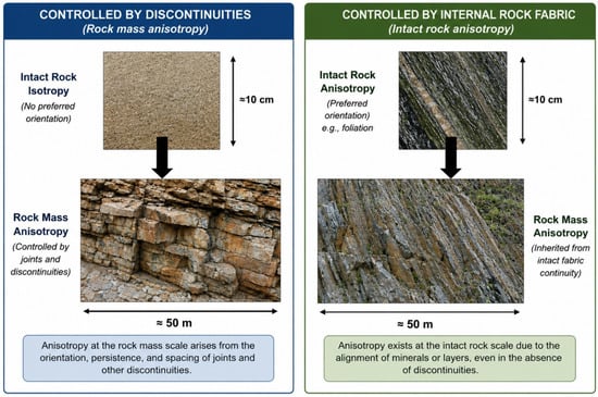
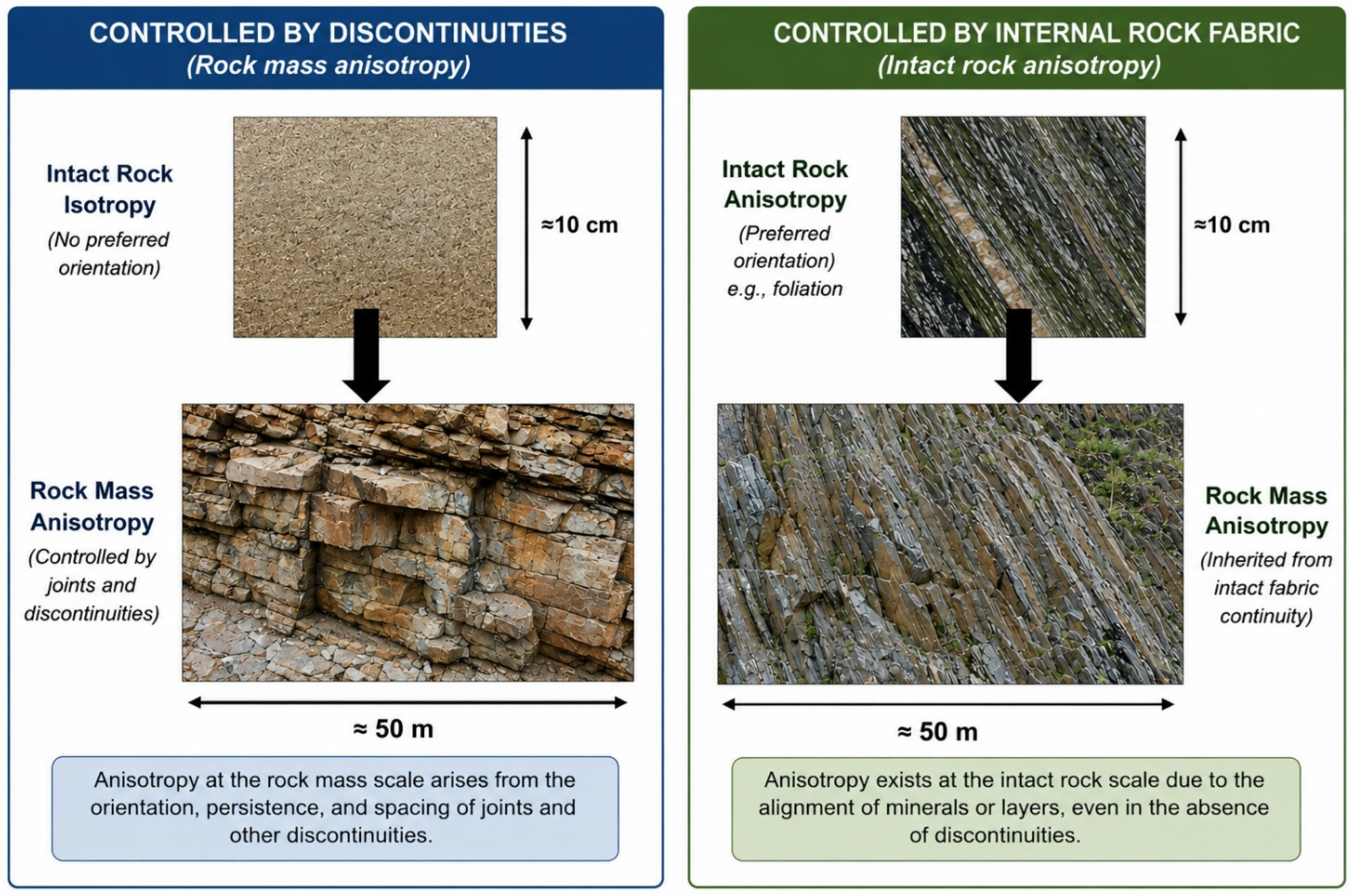

Disclaimer/Publisher’s Note: The statements, opinions and data contained in all publications are solely those of the individual author(s) and contributor(s) and not of MDPI and/or the editor(s). MDPI and/or the editor(s) disclaim responsibility for any injury to people or property resulting from any ideas, methods, instructions or products referred to in the content. |
© 2026 by the authors. Licensee MDPI, Basel, Switzerland. This article is an open access article distributed under the terms and conditions of the Creative Commons Attribution (CC BY) license.