


Abstract
Material selection plays a major role in determining the electrical performance of triboelectric nanogenerators (TENGs). Despite the exploration of several metal–organic frameworks (MOFs) for triboelectric energy harvesting, a large number of MOF materials remain unexplored as active triboelectric layers. Similarly, although TENGs have been widely investigated for powering low-power electronics and sensing systems, the utilization of their intrinsic high-voltage output for practical plasma and gas-ionization applications remains limited. In this work, a pristine MIL-101(Cr) MOF was explored as a new active triboelectric material for high-voltage energy harvesting applications. The triboelectric polarity of MIL-101(Cr) was systematically investigated using polarity-switching and surface potential studies. The relative triboelectric behavior of MIL-101(Cr) was evaluated against different counter materials, with the MIL-101(Cr)/silicone pair selected for further electrical characterization and high-voltage applications. The fabricated MIL-101(Cr)–silicone TENG delivered a high voltage of ~1.2 kV, a short-circuit current of ~110 μA, and a maximum power density of ~8.46 W/m2. Finally, the generated high-voltage output was successfully utilized to power helium, neon, argon, and mercury discharge tubes through simple biomechanical hand tapping, directly demonstrating self-powered plasma excitation and gas ionization. The present work opens new opportunities for utilizing MOF-based TENGs in high-voltage pulsed-power, plasma-generation, and self-powered discharge-based applications.
1. Introduction
The need for eco-friendly energy generation methods has emerged as a trend in recent years due to growing environmental impact and depletion of fossil-fuel energy [1]. The triboelectric nanogenerator (TENG) is one such green energy-harvesting method for converting ambient mechanical energy into electrical energy [2,3,4,5,6]. These devices have shown strong potential for powering microelectronic systems and low-power portable devices [7]. In this technology, electrical energy is generated through contact electrification, followed by electrostatic induction [8]. The field of TENGs has attracted widespread attention due to their inherent advantages, such as no limitation in the context of material selection, like piezoelectric nanogenerators or thermoelectric devices, lightweight, low manufacturing cost, simple device structure, compact, and high energy efficiency at a relatively low frequency [9]. However, TENGs face a major challenge: they naturally produce high output voltages but have very low short-circuit current and high internal impedance, which limits their practical applications. Despite these challenges, TENGs have found successful applications in sensors, wearable devices, biomechanical devices, and micro- and nano-energy harvesting devices for IoT [10,11,12].
To address low output current and high internal impedance, researchers are developing new strategies, such as using different triboelectric layer materials and power-management circuits. One fundamental factor governing the output performance is the current generation mechanism, which is not only dependent on the conductivity of the constituent materials but also involves effective charge creation, storage, separation, and charge transfer throughout the process. In this context, researchers explored a variety of materials, including polymers [13], metal oxides [14], hydrogels [15], cellulose [16], ferrofluids [17], perovskites [18], textiles [19], metal–organic frameworks (MOFs) [20], covalent organic frameworks (COFs) [21], and two-dimensional (2D) materials [22,23,24]. Among these materials, MOFs are suitable materials for addressing this gap compared to other materials. MOFs possess several unique advantages, such as tunable polarity through metal nodes and organic linkers, high dielectric polarization to improve charge storage, large surface area, and tunable pore networks to enhance charge trapping and avoid recombination, compared with other explored triboelectric materials. In addition, MOFs can form strong interfacial polarization when embedded in a polymer matrix or in conductive materials, thereby significantly improving rapid charge dissipation and reducing leakage currents. MOFs (HKUST-1, ZIF-8) were first incorporated in TENGs in 2019 [25,26], and in subsequent years, many other MOFs, such as ZIF-7,9,11,12,67, UiO-66, MIL-88A,125, ZUT-8,9,75, MOF-5, 303,525, ZTF-8, were explored in TENGs [20,21,27,28,29]. Despite these developments, many MOFs for TENGs remain unexplored. Therefore, in our study, we have selected a chromium-based MOF (MIL-101 Cr) as an active triboelectric material. MIL-101 (Cr) has been widely explored for adsorption, catalysis, photocatalysis, membrane preparation, sensor design, and drug delivery, but less so for energy-harvesting applications [30,31,32]. Prior studies have explored the application of MIL-101(Cr) as a functional filler for polymer TENGs and as an active polymer–MOF composite triboelectric material for energy generation purposes [33,34]. Building on these reports, this study investigates pristine MIL-101(Cr) as a dry-brush-coated triboelectric layer, systematically evaluates its relative triboelectric polarity with different counter materials, and explores its high-voltage output for gas-discharge excitation.
So far, most TENG application demonstrations have focused on powering LEDs and low-power electronic components, which do not fully exploit TENGs’ high-voltage output. In the reported literature, many MOF TENG devices have produced output voltages in the range of a few kV (Supporting Information (SI), Table S1) and have also been used to power LEDs and low-power electronic components. As a result, the unique high-electric-field capability of TENGs remains significantly underutilized, and high-voltage applications of TENG systems are still comparatively less explored. There are limited other high-voltage applications of TENG, including plasma generation [35], air purification [36,37,38], electrospinning [39], electrostatic sterilization [40,41] and X-ray generators [42]. Self-powered plasma generation using TENGs could enable applications such as air purification, surface modification, environmental remediation, and sterilization. However, the practical feasibility of these applications depends on the discharge characteristics, energy delivery, and operating conditions.
There is a pressing need to identify applications that can leverage TENG’s high intrinsic output voltage. Gas-discharge tubes are well suited to demonstrating TENGs’ high-voltage capabilities, as gas ionization requires a sufficiently strong electric field while the resulting discharge can be sustained at relatively low currents. In this context, the present study explores the use of a MIL-101(Cr)-based TENG to excite helium (He), neon (Ne), and argon (Ar) discharge tubes, demonstrating its potential for self-powered plasma excitation.
In this work, a high-voltage TENG based on pristine MIL-101(Cr) was developed for self-powered plasma excitation applications. The present work explores pristine MIL-101(Cr) as an active triboelectric material using a simple brush-coating strategy. The fabricated MIL-101(Cr)–silicone TENG delivered a high output voltage of ~1200 V, short-circuit current of ~110 μA, and a maximum power density of ~8.46 W/m2. Finally, the generated high-voltage output was successfully utilized to power helium, neon, and argon discharge tubes, directly demonstrating self-powered plasma excitation and electric-field-driven gas ionization.
2. Materials and Methods
2.1. Materials
Chromium nitrate (III) nonahydride extra pure (Cr(NO3)3·9H2O) and terephthalic acid (C8H6O4) were purchased from Sigma-Aldrich (Bangalore, India). Hydrofluoric acid (HF) and dimethylformamide (DMF) were purchased from Sisco Research Laboratories (SRL chemicals,) (Mumbai, India). All the chemicals were used without any further purification.
2.2. Synthesis of MIL-101(Cr)
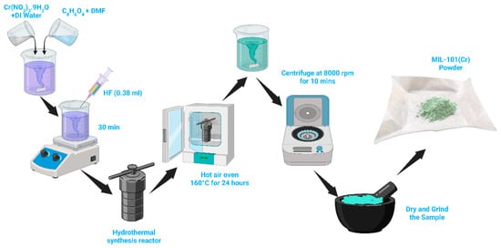
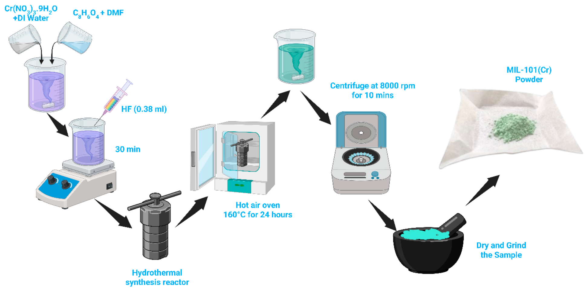
A solvothermal method was employed for the synthesis of MIL-101(Cr) using chromium(III) nitrate nonahydrate (Cr(NO3)3·9H2O) and terephthalic acid (H2BDC) as the metal precursor and organic linker, respectively, in the presence of hydrofluoric acid (HF) as a mineralizing agent. The synthesis procedure was adapted from previously reported methods, and a schematic of the synthesis is shown in Figure 1 [43,44,45]. Briefly, 2 g (5 mmol) of Cr(NO3)3·9H2O was dissolved in deionized water under continuous magnetic stirring at room temperature until a clear homogeneous solution was obtained. In a separate vessel, 0.83 g (5 mmol) of H2BDC was dissolved in DMF. The organic linker solution was then added sequentially to the chromium precursor solution under constant stirring, maintaining a total solvent volume of approximately 30 mL with a controlled DMF/H2O ratio.
Figure 1.
Illustration of the synthesis process for MIL-101(Cr) crystalline powder.
Next, 0.38 mL of HF solution was gradually added to the reaction mixture, followed by magnetic stirring for another 30 min to promote coordination between Cr3+ cations and terephthalate ligands. Subsequently, the obtained homogeneous mixture was then transferred into an 80 mL Teflon-lined stainless-steel autoclave and heated at 160 °C for 24 h. During solvothermal treatment, Cr3+ ions undergo controlled hydrolysis to form μ3-oxo-centered Cr3O trinuclear clusters, which serve as secondary building units. The terephthalate linkers bridge these chromium trimers to construct the characteristic MTN-type mesoporous framework of MIL-101(Cr). HF plays a critical role in stabilizing cluster formation and regulating defect density, while the DMF/H2O ratio governs hydrolysis kinetics, nucleation rate, and crystal growth behaviour.
After completion of the reaction, the autoclave was allowed to cool naturally to room temperature. The resulting green crystalline product was collected by centrifugation at 8000 rpm for 10 min and thoroughly washed with deionized water and DMF separately at 65 °C several times to remove unreacted precursors and residual impurities. The obtained solid was then dried under vacuum at 135 °C for 4 h to eliminate residual solvent and guest molecules. The activated light green MIL-101(Cr) powder was subsequently used for further characterization and application studies. The light green color of the powder indicates the formation of MIL-101(Cr), as supported by the literature [46,47].
2.3. Characterization of MIL-101(Cr)
The synthesized MIL-101(Cr) powder was systematically characterized to evaluate its phase purity, crystallinity, surface morphology, elemental composition, and chemical bonding. The crystal structure and phase formation were examined using an X-ray diffractometer (XRDYNAMIC 500, Anton Paar GmbH, Graz, Austria). Surface morphology and elemental composition were investigated by field-emission scanning electron microscopy (FESEM; JEOL JSM-IT800, JEOL Ltd., Akishima, Tokyo, Japan) coupled with elemental analysis. The chemical states and surface elemental composition were analyzed using X-ray photoelectron spectroscopy (XPS) by using a DESA-150 electron analyzer (Staib Instruments, Langenbach, Germany) equipped with a Mg Kα X-ray source (1253.6 eV). Fourier-transform infrared spectroscopy (FT-IR) (Bruker Optik GmbH, Ettlingen, Germany) was recorded in the 400−4000 cm−1 range using a Bruker α-II spectrophotometer in attenuated total reflection (ATR) mode to study the bonding between the metal center and organic linker. The BET specific surface area, total pore volume, and pore size of the synthesized MIL-101 (Cr) were derived from N2 adsorption–desorption isotherm at 77 K using a Quantachrome Autosorb iQ-C-XR-XR gas sorption analyzer (Quantachrome Instruments, Boynton Beach, FL, USA).
2.4. Fabrication and Testing of MIL-TENG Device
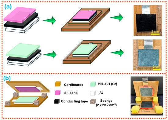
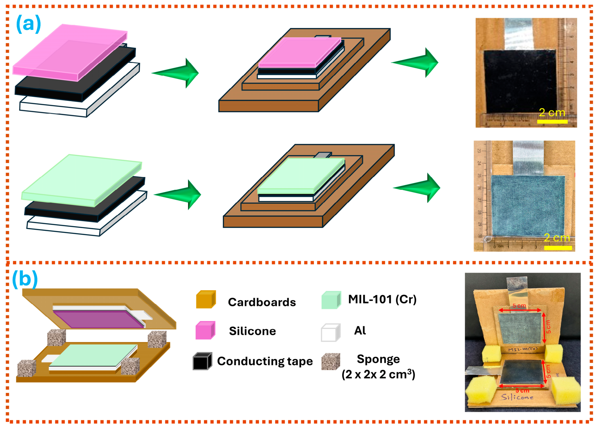
The schematic of the MIL-101(Cr)-based TENG fabrication steps is shown in Figure 2a. In this work, vertical contact-separation (VCS) working mode was selected for device fabrication. In VCS mode, TENG devices require two frictional layers: one fixed as MIL-101 (Cr) and the other varied to find the optimal pair for better performance. For the preparation of the MIL-101 (Cr) frictional layer, aluminum foil (5 × 5 cm2) was first attached with conducting tape, and MIL-101 (Cr) powder was then coated using brush coating. After each coating step, loosely adhered powder was removed using an air gun. The process was repeated until a uniform and continuous MIL-101(Cr) layer (5 × 5 cm2) was obtained on the substrate. Film continuity was assessed by measuring resistance across the fully coated surface, with the coating exhibiting high resistance in the megaohm range. As the bottom carbon layer is a conducting layer, and after it was coated with MIL-101 (Cr), the higher resistance confirms the full coverage of MIL-101 (Cr) across the carbon layer. Mass loading of MIL-101(Cr) was found to be around 7 mg, based on the difference in substrate weight before and after coating. To determine the coated-layer thickness, we performed optical and electron microscopy on a cross-sectional view of the sample. We could not obtain reliable quantitative measurements due to the irregular substrate surface and particulate morphology of the deposited layer. We acknowledge that manual coating may introduce variations in thickness and uniformity, which limit this fabrication approach. Future studies may explore more controlled deposition techniques to improve coating reproducibility and scalability.
Figure 2.
(a) Stepwise assembly and corresponding photographs of the silicone rubber and MIL-101(Cr) frictional units, and (b) detailed schematic of the device architecture and photograph of the completed MIL-101(Cr)–silicone TENG.
For the counter triboelectric layer (5 × 5 cm2), a silicone rubber film was attached to aluminum using conductive tape. The preparation details for the silicone rubber film are described in other reports [48]. Figure 2a shows photographs of the fabricated frictional layers. Both aluminum foils with the frictional layer were attached to separate cardboard sheets and placed one on top of the other, so that the silicone rubber surface and the MIL-101 (Cr) film face each other. A finite gap of 1 cm was formed between the frictional layers with the help of sponge spacers (2 × 2 × 2 cm3). Figure 2b shows a schematic of the device and a photograph of the assembled device with an active contact area of 5 × 5 cm2.
The same procedure was followed to fabricate different TENG devices with a fixed MIL-101(Cr) and opposing friction layers of Al, Cu, PET, PMMA, FEP, and PTFE. A total of 7 TENG devices were fabricated, and all devices were tested under the same conditions. The electrical performance of the fabricated TENGs was assessed under ambient conditions by manual hand tapping at a frequency of 3–4 Hz. The voltage and current signals were measured using a digital oscilloscope (GW Instek GDS-1102B, Good Will Instrument Co., Ltd., New Taipei City, Taiwan) with a 100× attenuating voltage probe and a low-noise current preamplifier (Stanford Research Systems SR570,Sunnyvale, CA, USA), respectively. Load-dependent measurements were performed using a decade resistance box (Nvis 705, Nvis Technologies Pvt. Ltd., Indore, India). The operational durability of the devices was examined using a cyclic force generator (Holmarc TBM-02,Holmarc Opto-Mechatronics Ltd., Kochi, India) under a force of 10 N at 4 Hz. The schematic illustrations of the electrical measurement configurations and application circuits are provided in SI, Figure S1.
3. Results
3.1. Material Characterization
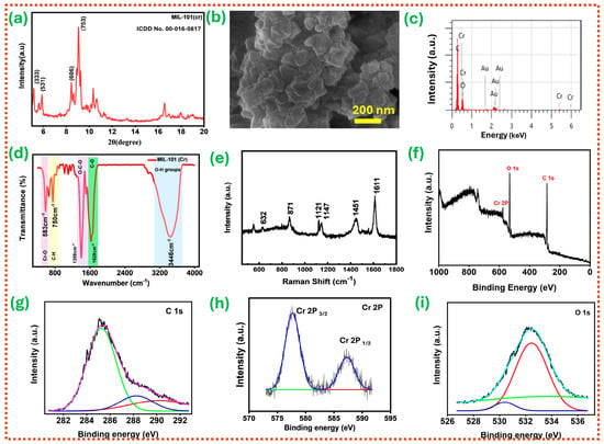
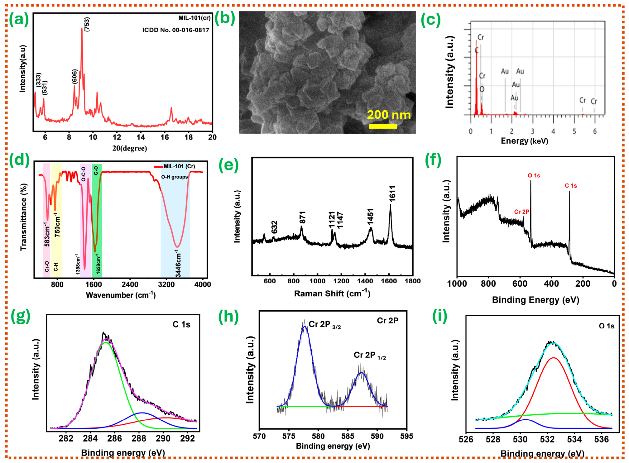
Figure 3a presents the powder X-ray diffraction (PXRD) pattern of the synthesized MIL-101(Cr) powder. The characteristic diffraction peaks observed at 2θ ≈ 5.0°, 5.8°, 8.4°, and 9.0°, are indexed to the (333), (531), (606), and (753) crystallographic planes, respectively. The reported XRD pattern and major diffraction peaks well matched with reported literature and the CCDC deposition 605510 [49,50,51,52]. The low-angle reflections (<10°) originate from the ordered arrangement of the large cages intrinsic to the MIL-101 architecture [53,54]. Importantly, no additional diffraction peaks corresponding to residual terephthalic acid, chromium hydroxide species, or Cr2O3 phases are detected, indicating high phase purity of the MIL-101 (Cr). The surface morphology of MIL-101(Cr) was subsequently examined using field-emission scanning electron microscopy (FESEM), and the resulting micrograph is presented in Figure 3b. The FESEM images reveal that MIL-101(Cr) consists of densely packed polyhedral nanocrystals forming clustered aggregates. The observed morphology is consistent with the reported literature [55,56,57]. The EDX spectrum shown in Figure 3c shows the major constitutional elements, C and Cr, present in MIL-101 (Cr). Additional elements include Au from the gold coating used for SEM sample preparation and oxygen from surface oxidation of the prepared sample.
Figure 3.
Structural, chemical, and morphological characterization of MIL-101(Cr). (a) XRD pattern, (b) surface morphology, (c) EDX spectrum, (d) FTIR spectrum, (e) Raman spectrum, and (f–i) XPS survey spectrum, XPS spectrum C 1s, Cr 2p, O 1s.
To identify the functional groups in the prepared MIL-101(Cr), we recorded the FTIR spectrum, shown in Figure 3d. The broad absorption band observed in the range of 2800–3800 cm−1 is attributed to O-H stretching vibrations [58]. The band at 1628 cm−1 is assigned asymmetric stretching of the carboxylate/C=O-related coordinated linker environment, confirming the binding of H2BDC to the Cr3+ nodes [59,60]. The band at 1398 cm−1 is attributed to the symmetric stretching vibrations of the coordinated carboxylate groups (O-C-O) [61,62]. The band at 583 cm−1 is assigned to Cr-O stretching, indicating the formation of chromium–oxo coordination units within the framework. The absorption at 750 cm−1 corresponds to aromatic C-H bending of the benzene ring from the terephthalate linker [62]. Altogether, these characteristic vibrational features confirm the successful formation of the MIL-101(Cr) framework, with no detectable unreacted linker impurities.
Figure 3e shows the Raman spectrum of the synthesized MIL-101 (Cr), revealing prominent peaks characteristic of the chromium–terephthalate framework. For instance, the peak at 632 cm−1 corresponds to low-frequency vibrational modes of the chromium-oxygen coordination environment, whereas the peak around 871 cm−1 corresponds to C-H bending modes of the aromatic terephthalate linker. The two well-defined peaks at 1121 and 1147 cm−1 correspond to in-plane C-H bending modes and carbon–carbon stretching modes of the aromatic rings. The peak at 1451 cm−1 is related to aromatic ring vibrations and coordinated carboxylates, while the prominent peak around 1611 cm−1 is due to C=C stretching vibrations of the aromatic benzene rings. These observations are consistent with previous studies reporting Raman spectra of MIL-101(Cr) [57,63].
The chemical composition and oxidation states of MIL-101(Cr) were investigated using X-ray photoelectron spectroscopy (XPS). Figure 3f shows the survey of MIL-101 (Cr) and confirms the presence of Cr, O, and C, with no impurity peaks, such as metallic chromium or chromium oxide. Figure 3g depicts the high-resolution C 1s spectrum, which was deconvoluted into components from different carbon environments in the terephthalate linker. The main peak at 284.6–284.8 eV is from C-C/C=C bonds of the aromatic benzene ring. A secondary peak at 286.2–286.5 eV corresponds to C-O bonds in carboxylate groups. The higher binding energy peak at 288.5–289.0 eV is assigned to O-C=O (carboxylate carbon), indicating successful coordination of the terephthalate linker to chromium nodes. The high-resolution Cr 2p spectrum presented in Figure 3h shows the spin–orbit split peaks at around 576–577 eV (Cr 2p3/2) and 586–587 eV (Cr 2p1/2). The ~9.5–10 eV spin–orbit splitting indicates Cr3+, matching chromium’s state in MIL-101(Cr). The absence of peaks at ~574 eV (metallic Cr) or higher-binding-energy signals linked to Cr6+ confirms that chromium is only in the trivalent form within the framework. The deconvoluted O 1s spectrum (Figure 3i) shows several oxygen environments: the main component at about 531.5–532.0 eV, assigned to coordinated carboxylate oxygen (O-C=O) bonded to chromium; a secondary peak at 530.0–530.5 eV, linked to Cr-O-Cr lattice oxygen in μ3-oxo bridges within Cr3O clusters; and a higher binding energy peak at 532.5–533.5 eV, due to adsorbed water or surface hydroxyl groups, consistent with MIL-101(Cr)’s porous nature (total pore volume = 0.61 cc/g) and high specific surface area (896.8 m2/g) and the presence of coordinated water molecules. The textural properties of synthesized MIL-101(Cr) are mentioned in SI, Figure S2.
3.2. Electrical Characterization of the TENG
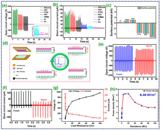
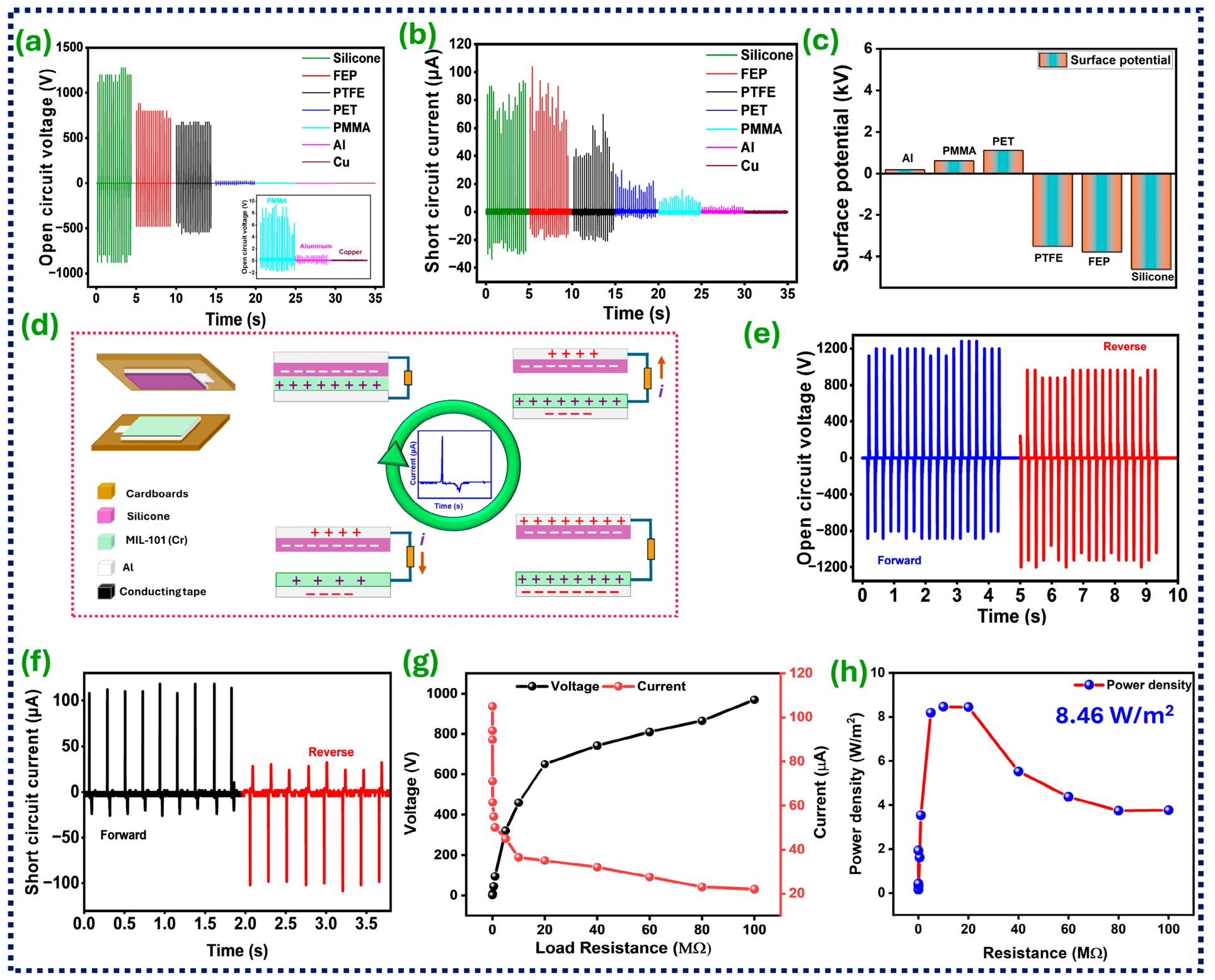
Figure 4a,b present the open-circuit voltage (Voc) and short-circuit current (Isc) generated by MIL-101(Cr)-based TENGs paired with different counter layers, namely silicone rubber, FEP, PTFE, PET, PMMA, Al, and Cu. This comparative approach helps us identify a suitable material pair for subsequent device characterization. The responses are clearly highlighted in different colors to enable a clear comparison among the tested triboelectric pairs. Each triboelectric pair produces a different electrical output because of differences in electron affinity. Further, MIL-101(Cr) generates comparatively higher electrical outputs when paired with strongly electron-accepting materials such as silicone rubber, FEP, and PTFE, whereas it produces lower outputs with tribo-positive counter layers. Based on the magnitude of the observed electrical output, it is assumed that MIL-101(Cr) predominantly behaves as an electron-donating, tribopositive material. This assertion is supported by measurements of the surface potential of the material film after contact with different tribomaterials, as shown in Figure 4c. These measurements clearly reveal that MIL-101 (Cr) predominantly acts as a tribo-positive material. The charge transfer dynamics can be understood from the surface potential values. When MIL-101 (Cr) is paired with different opposite materials (silicone, FEP, PTFE, Kapton), electrons transfer from MIL-101 (Cr) to the opposite materials, making it behave like a tribo-positive material. By contrast, when paired with Al, PMMA, or PET, electrons transfer from the opposite layers to MIL-101 (Cr), behaving like a tribo-negative material. Based on the magnitude of the surface potentials in both cases, MIL-101 (Cr) predominantly acts as a tribo-positive material. The observed tribo-positive behavior of MIL-101(Cr) may be influenced by its surface chemistry and metal–ligand coordination environment. Previous studies have demonstrated that organic linker chemistry and surface functionalization can modify the triboelectric behavior of MOFs, including MIL-101(Cr) [64,65]. However, the specific contributions of Cr-based metal nodes and carboxylate linkers to interfacial charge transfer remain unclear and require further investigation. Finally, among all the tested triboelectric pairs, the MIL-101 (Cr)–silicone rubber pair exhibited the highest electrical response and was selected for the subsequent electrical characterizations of the TENG.
Figure 4.
Electrical performance of MIL-101 (Cr)-based TENG with different counter-frictional materials. (a) Voc and (b) Isc (inset magnified view), (c) surface potential values of MIL-101 (Cr) after repeated contact with different frictional layers, (d) working mechanism of the TENG, electrical performance of the MIL-101 (Cr)TENG in switching polarity configuration, (e) Voc and (f) Isc, (g) load-dependent output voltage and current, and (h) load-dependent power density.
Following confirmation of the tribo-positive behavior of MIL-101(Cr), the working mechanism of MIL-101 (Cr)–silicone TENG is schematically presented in Figure 4d. In the initial state, the two triboelectric layers remain separated, resulting in no potential difference between the electrodes and no current flow through the external circuit. Upon application of a hand-tapping force, the MIL-101 layer comes into contact with the silicone. Electrons are transferred from MIL-101(Cr) to silicone because of their different electron affinities. Consequently, MIL-101(Cr) acquires positive surface charges, whereas silicone becomes negatively charged. Upon releasing the force, separation of the layers generates a potential difference between the electrodes that drives electrons through the external circuit until equilibrium is reached. This produces one electrical pulse in the external circuit. When the force is reapplied, the layers move closer, disrupting this equilibrium and inducing electron flow in the opposite direction. Thus, repeated contact and separation generate an alternating electrical output.
Figure 4e,f show the VOC and ISC of the MIL-101(Cr)–silicone-based TENG in the switching polarity test configuration. In this test configuration, device output leads are interchanged while connecting to the measuring device [66]. After reversing the connection, the output signal polarity inverted while maintaining the same magnitude. This behavior clearly confirms that the device’s intrinsic triboelectric effect generates the signals, rather than external disturbances such as environmental noise, electromagnetic interference, or instrumentation artifacts. The MIL-101(Cr)–silicone-based TENG produced a positive peak VOC of ~1200 V and an ISC of ~110 μA. Furthermore, the charge transferred during TENG operation was recorded with an electrometer and is shown in SI, Figure S3. It exhibited a peak-to-peak variation of approximately 264 nC per one complete contact–separation cycle. The transferred charge density was found to be 10.57 nC/cm2 for an effective contact area of 25 cm2 (5 × 5 cm2).
The load-dependent electrical characteristics of the MIL-101(Cr)–silicone TENG were examined by varying the external resistance with a decade resistance box. Figure 4g graphically presents the peak output voltage and current at different load resistances. As the load resistance increases, the output voltage gradually rises and eventually approaches saturation under near-open-circuit conditions. In contrast, the output current progressively decreases due to ohmic losses in the circuit. These opposing voltage and current trends characterize TENGs and arise from their intrinsically high internal impedance. We also evaluated the instantaneous power density using P = V2/(RLA), where V is the positive peak voltage across the load, RL is the external resistance, and A is the device’s effective contact area (25 cm2). Figure 4h shows how power density varies with external load resistance. Power density increases with resistance, reaches a maximum of 8.46 W/m2 at 10 MΩ, and then declines. According to the maximum power transfer theorem, the device delivers maximum power to the load when its internal impedance matches the load resistance. For the TENG, the 10 MΩ point can be considered the load-matching point. The electrical energy per contact–separation event was estimated at a load resistance of 10 MΩ by integrating the squared current over selected peak intervals, following the approach reported in the literature [67,68]. The average energy was approximately 118.58 µJ per peak pair, with a corresponding mean peak-window power of 2.92 mW. Furthermore, the influence of operating parameters, including applied force, tapping frequency, separation distance between the triboelectric layers, device contact area, and relative humidity, on the electrical performance of the MIL-101(Cr)–silicone TENG was investigated. The corresponding results are presented in SI, Figure S4. These results provide additional insight into the device response under different operating conditions.
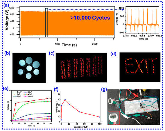
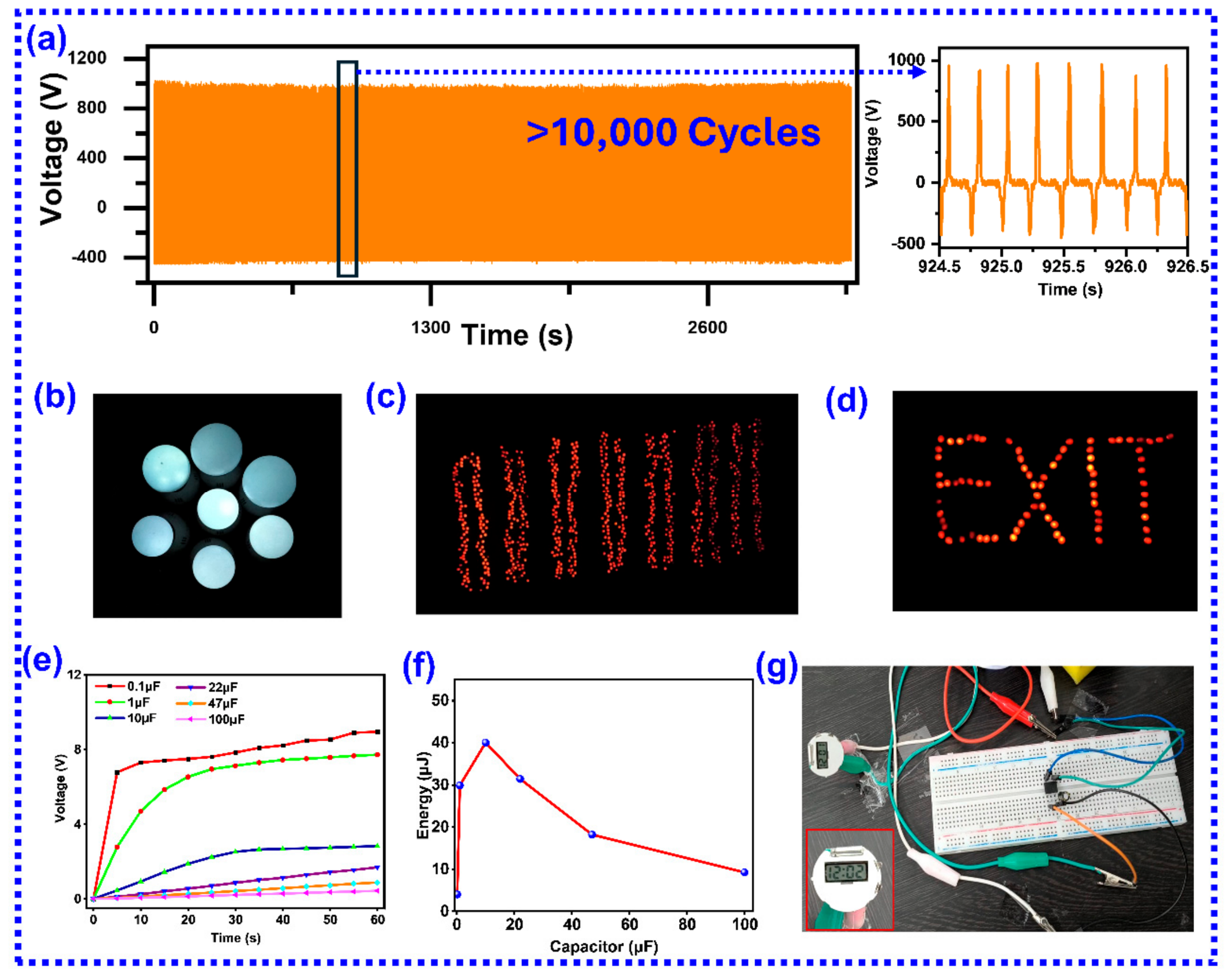
Finally, the mechanical robustness and long-term performance of the fabricated device were evaluated through extended cyclic testing over 10,000 continuous operation cycles. The TENG responses to the 10,000 test cycles are shown in Figure 5a. The MIL-101(Cr)–silicone TENG maintains a nearly constant output profile throughout the entire testing period, with no observable decline in peak voltage or distortion in the signal waveform. Furthermore, to evaluate output-voltage stability under manual hand tapping, we tested the MIL-101(Cr)–silicone TENG over approximately 2500 hand-tapping cycles, and the responses are shown in SI, Figure S5. The device exhibited a relatively stable voltage response, with minor fluctuations attributed to variations in mechanical excitation. We also examined the surface morphology of the MIL-101(Cr) coating using optical microscopy before and after the stability test and the results are shown in SI, Figure S6. We observed noticeable differences in surface features after repeated contact–separation cycles, possibly due to mechanical deformation or rearrangement of the coating. Despite these morphological differences, the device maintained a relatively stable electrical output over large test cycles. Overall, the long-term stability under machine and hand tapping demonstrates that the MIL-101(Cr)-based TENG exhibits excellent operational durability and sustained energy-harvesting capability, making it a promising material for long-term practical applications in self-powered systems.
Figure 5.
(a) Long−term working stability of the TENG device over 10,000 cycles and enlarged view of a few cycles, ON condition photographs of the (b) LED lamps, (c) LEDs, (d) EXIT sign board, (e) capacitor charging profiles, (f) stored electrical energy versus load capacitance, and (g) direct powering of the portable digital watch.
The electrical energy generation capability of the MIL-101 (Cr) TENG was initially verified by driving various loads, including LED lamps. In this setup, the TENG output was first rectified using a DB107 IC bridge rectifier, and the rectified electrical output was connected to series-connected LED lamps and to series-connected 840 LEDs separately each time. The electrical energy generated by each hand tap was sufficient to power LED lamps. Real-time photographs during testing are shown in Figure 5b,c, and real-time test videos are provided in SI, Videos S1–S3. Further, we arranged the LEDs to read EXIT, and the EXIT sign board is easily powered by the TENG, as shown in Figure 5d. This TENG-powered signboard display opens new applications for self-powered indicators in emergency situations.
Figure 5e presents the charging profiles of different capacitors (0.1 µF, 1 µF, 10 µF, 22 µF, 47 µF, and 100 µF) under identical hand-tapping conditions for 60 s. The charging behavior clearly depends on the capacitance value, with smaller capacitors reaching higher voltages more rapidly. Figure 5f shows the corresponding stored energy values, calculated using E = 1/2 CV2. The 10 µF capacitor achieved a maximum stored energy of approximately 40 µJ, indicating an optimal balance between load capacitance and the resulting voltage. Figure 5g shows a photograph of the digital watch powered by the TENG. In this setup, energy generated by each hand tap on the TENG is stored in a capacitor and simultaneously used to power the digital watch. The digital watch was continuously powered as long as mechanical energy from hand tapping was applied to the TENG. This demonstrates the self-powered operation of portable electronic devices. The real-time demonstration video is provided in SI, Video S4.
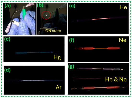
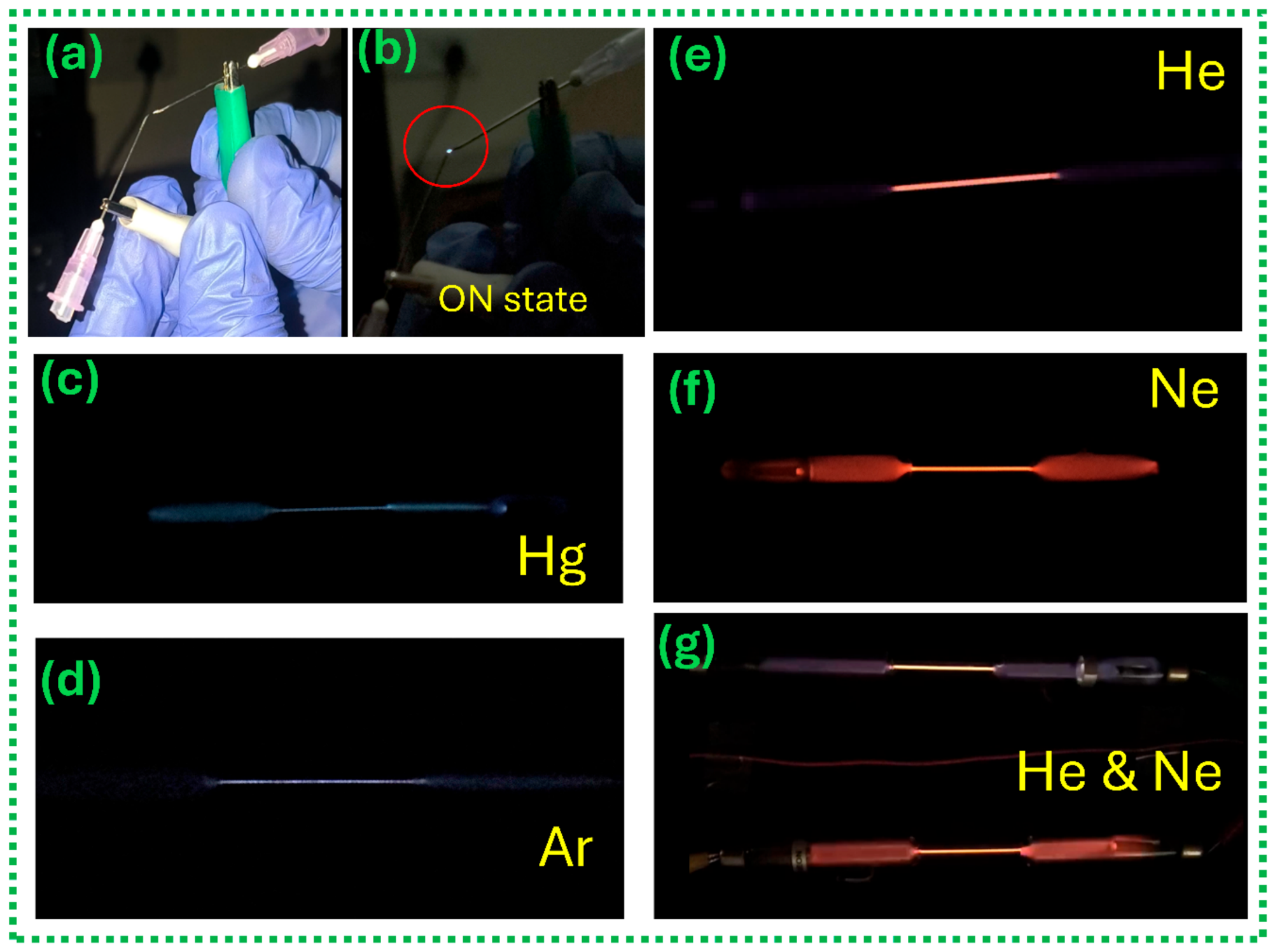
Finally, the practical use of the high-voltage output from the MIL-TENG was demonstrated through direct air-gap spark discharge and self-powered gas plasma excitation under ambient conditions, as shown in Figure 6. Figure 6a shows the experimental setup used for demonstrating direct electrical discharge generated by the TENG output. A visible air-gap spark was observed between the metallic electrode tips shown in Figure 6b and SI, Video S5, confirming the generation of sufficiently strong electric fields capable of dielectric breakdown in air. The corresponding real-time spark discharge photograph under dark conditions is shown in the inset, where the localized bright plasma spot (highlighted by the red circle) directly evidences the generation of high-voltage discharge from the MIL-TENG.
Figure 6.
Demonstration of high-voltage applications of the fabricated MIL-TENG: (a,b) direct air-gap spark discharge and (c–g) photographs of the different discharge tubes with visible glow excited by TENG output voltage.
Figure 6c–g present real-time photographs of different discharge tubes powered by the MIL-TENG under ambient conditions, and the corresponding test videos are provided in SI, Video S6. Distinct plasma emissions from Hg, Ar, He, and Ne were clearly observed, confirming successful gas breakdown and electric-field-driven excitation. The variation in emission color arises from the characteristic electronic transitions and emission spectra of the respective gases under plasma conditions. The successful activation of discharge tubes demonstrates that the fabricated TENG can effectively deliver sufficient electrical potential for plasma generation. This result further highlights the suitability of triboelectric nanogenerators for high-voltage pulsed-power applications and provides direct evidence that MOF-based TENGs can be used beyond conventional LED powering toward advanced self-powered plasma and discharge-based systems.
4. Conclusions
In conclusion, a pristine MIL-101(Cr) MOF-based high voltage TENG was fabricated and utilized in self-powered plasma excitation applications. The fabricated MIL-101(Cr)–silicone TENG exhibited a high output voltage of ~1200 V, a current of ~110 μA, and a maximum power density of ~8.46 W m−2. The relative tribo-positive nature of MIL-101(Cr) was experimentally verified. The fabricated device demonstrated high stability over 10,000 test cycles. Further, it successfully powered LEDs, a digital watch, and gas discharge tubes. Importantly, the successful excitation of He, Ne, Ar, and Hg plasma directly demonstrates the capability of MOF-based TENGs for high-voltage pulsed-power and self-powered plasma applications beyond conventional low-power electronics. Although MIL-101(Cr)-based TENGs show promising results for energy harvesting, the use of hazardous chemicals during synthesis and the potential for residual solvent retention require further consideration. Future studies should focus on greener synthesis routes.
Supplementary Materials
The following supporting information can be downloaded at: https://www.mdpi.com/article/10.3390/nanoenergyadv6040036/s1, Video S1: Powering LED lamps, Video S2: Powering LEDs, Video S3: Powering the EXIT LED sign board, Video S4: Continuous powering of the digital watch, Video S5: Generation of air-gap spark discharge, Video S6: Powering different discharge tubes. Figure S1: Schematic illustrations of the electrical measurement and application circuits of the MIL-101(Cr)-based TENG: (a) short-circuit current measurement using an SR570 current preamplifier and oscilloscope; (b) load-dependent voltage measurement; (c) load-dependent current measurement; (d) powering LEDs through a full-wave bridge rectifier; and (e) capacitor charging and powering a digital watch using a rectifier and 47 µF capacitor, Figure S2: N2 adsorption-desorption isotherm of MIL-101 (Cr) at 77 K, Figure S3: Transferred charge characteristics of the MIL-101(Cr)–silicone TENG showing an individual contact–separation cycle and stable charge transfer over repeated cycles, Figure S4: Effect of operating parameters on the output voltage of the MIL-101(Cr)–silicone TENG: (a) manual tapping using different numbers of fingers and the palm, (b) separation distance (0.5–2 cm), (c) device contact area (2 × 2 to 5 × 5 cm2), (d) tapping frequency (1–7 Hz), and (e) relative humidity (44–95%). All measurements were performed under manual tapping conditions, Figure S5: Long-term stability of the TENG device over 2500 hand tapping cycles, Figure S6: Optical microscopy images of the MIL-101(Cr)-coated surface before and after the stability test. Table S1: Comparison of MOF-, MOF-derived-, and related porous-framework-based TENGs.
Author Contributions
R.P.: Data Curation; Formal Analysis; Investigation; Methodology; Writing—Original Draft; Writing—Review and Editing; P.R.: Resources; Data Curation; Formal Analysis; Investigation; Visualization; Writing—Review and Editing; A.W.: Data Curation; Formal Analysis; Methodology; R.K.R.: Formal Analysis; Project Administration; Resources; Writing—Review and Editing; H.D.: Conceptualization; Project Administration; Formal Analysis; Writing—Review and Editing; U.K.K.: Conceptualization; Project Administration; Resources; Supervision; Validation; Visualization; Writing—Original Draft; Writing—Review and Editing. All authors have read and agreed to the published version of the manuscript.
Funding
The authors gratefully acknowledge the financial support provided by the Board of Research in Nuclear Sciences (BRNS), Department of Atomic Energy (DAE), Government of India, under the research project sanction (grant no: 59/14/06/2024-BRNS/717).
Data Availability Statement
The original contributions presented in this study are included in the article/Supplementary Material. Further inquiries can be directed to the corresponding authors.
Acknowledgments
R.K.R. and U.K.K. acknowledge DAE-BRNS (59/14/06/2024-BRNS/717) for funding support to carry out this research work.
Conflicts of Interest
The authors declare no conflicts of interest.
References
- Chen, N.; Usman, M. Energy Use, Energy Depletion, and Environmental Degradation: Exploitation of Natural Resources. Nat. Resour. Forum 2025, 49, 3984–3995. [Google Scholar] [CrossRef] [Scilit]
- Udofa, E.S.; Mohamed Ali, M.S.; Leow, P.L. Recent Development in Triboelectric Nanogenerators: A Review. J. Mater. Sci. Mater. Electron. 2026, 37, 6. [Google Scholar] [CrossRef] [Scilit]
- Liu, M.-N.; Li, X.; Zheng, G.; Yin, F.; Li, R.; Zhang, J.; Ramakrishna, S.; Long, Y.-Z. Research Progress in Triboelectric Nanogenerators Based on New Inorganic Materials. iScience 2026, 29, 114601. [Google Scholar] [CrossRef] [Scilit] [PubMed]
- Chittibabu, S.K.; Vijayababu, M.; Natarajan, K.; Sharma, N.; Chandrasekhar, A.; Chintagumpala, K.; Lin, Z.-H. Biomorphic Honeycomb-Engineered Ti2C MXene/PDMS Composite Triboelectric Nanogenerator for Eco-Conscious Energy Harvesting and Autonomous Analysis of Perishable Food Freshness. Chem. Eng. J. 2026, 533, 174961. [Google Scholar] [CrossRef] [Scilit]
- Yeh, H.-Y.; Kaswan, K.; Haji, H.S.; Joshi, R.; Khan, A.; Parashar, P.; Yu, J.-H.; Hsu, W.-Z.; Chen, P.-Y.; Chu, J.P.; et al. Enhanced Energy Harvesting through Lubricant-Water Interaction on a Superoleophobic Stainless Steel@cellulose Ester Nanogenerator. Nano Energy 2025, 139, 110958. [Google Scholar] [CrossRef] [Scilit]
- Chatterjee, S.; Saha, S.; Barman, S.R.; Khan, I.; Pao, Y.-P.; Lee, S.; Choi, D.; Lin, Z.-H. Enhanced Sensing Performance of Triboelectric Nanosensors by Solid-Liquid Contact Electrification. Nano Energy 2020, 77, 105093. [Google Scholar] [CrossRef] [Scilit]
- Parveena, A.; Muhammed Swalihu, P.M.; Jayadas, S.; Haridas, K.; Gopika, M.; Thomas, S.; Rouxel, D.; Royaud, I.; Kalarikkal, N.; Chitra Lekha, C.S. Powering the Future of Electronics: A Comprehensive Review of Triboelectric Nanogenerators. Eur. Polym. J. 2026, 253, 114753. [Google Scholar] [CrossRef] [Scilit]
- Fan, F.R.; Tian, Z.Q.; Lin Wang, Z. Flexible Triboelectric Generator. Nano Energy 2012, 1, 328–334. [Google Scholar] [CrossRef] [Scilit]
- Li, X.; Yin, L.; Li, P.; Wang, J. Phase-Shift Engineered Triboelectric Nanogenerators for Constant-Voltage Output and Efficient Energy Harvesting. Commun. Mater. 2026, 7, 37. [Google Scholar] [CrossRef] [Scilit]
- Cheng, G.; Zheng, H.; Yang, F.; Zhao, L.; Zheng, M.; Yang, J.; Qin, H.; Du, Z.; Wang, Z.L. Managing and Maximizing the Output Power of a Triboelectric Nanogenerator by Controlled Tip–Electrode Air-Discharging and Application for UV Sensing. Nano Energy 2018, 44, 208–216. [Google Scholar] [CrossRef] [Scilit]
- Gu, G.; Liu, Q.; Gao, H.; Zhang, J.; Wang, Z.L. Triboelectric E-Skin for Robotic Perception of Hazardous Chemical Leaks. Adv. Mater. 2026, 38, e74261. [Google Scholar] [CrossRef] [Scilit] [PubMed]
- Lin, J.C.; Kaswan, K.; Chatterjee, S.; Wu, Y.W.; Kumar Sharma, M.; Ranjan, A.; Roy Barman, S.; Lin, Y.Z.; Burnouf, T.; Boireau, W.; et al. CuO NWs Boosted Triboelectric Microfluidic Nanosensor Functionalized by Collagen-Protein Interactions for Real-Time Platelet Count Monitoring. Chem. Eng. J. 2024, 490, 151586. [Google Scholar] [CrossRef] [Scilit]
- Shanbedi, M.; Ardebili, H.; Karim, A. Polymer-Based Triboelectric Nanogenerators: Materials, Characterization, and Applications. Prog. Polym. Sci. 2023, 144, 101723. [Google Scholar] [CrossRef] [Scilit]
- Potu, S.; Kulandaivel, A.; Gollapelli, B.; Khanapuram, U.K.; Rajaboina, R.K. Oxide Based Triboelectric Nanogenerators: Recent Advances and Future Prospects in Energy Harvesting. Mater. Sci. Eng. R Rep. 2024, 161, 100866. [Google Scholar] [CrossRef] [Scilit]
- Sun, E.; Wang, Y.; Zhang, Z.; Chen, Y.; Shoaib, M.; Cao, X.; Wang, N. Hydrogel-Based Triboelectric Nanogenerators: Current Progress and Future Perspectives. Adv. Funct. Mater. 2025, 35, e11382. [Google Scholar] [CrossRef] [Scilit]
- Annamalai, P.K.; Nanjundan, A.K.; Dubal, D.P.; Baek, J.B. An Overview of Cellulose-Based Nanogenerators. Adv. Mater. Technol. 2021, 6, 2001164. [Google Scholar] [CrossRef] [Scilit]
- Kulandaivel, A.; Potu, S.; Babu, A.; Madathil, N.; Velpula, M.; Rajaboina, R.K.; Khanapuram, U.K. Advances in Ferrofluid-Based Triboelectric Nanogenerators: Design, Performance, and Prospects for Energy Harvesting Applications. Nano Energy 2024, 120, 109110. [Google Scholar] [CrossRef] [Scilit]
- Jin, Z.; Xing, H.; Hu, Y.; Cho, Y. Perovskite-Based Triboelectric Nanogenerator and Its Application Towards Self-Powered Devices. Nanoenergy Adv. 2025, 5, 2. [Google Scholar] [CrossRef] [Scilit]
- Dejene, B.K.; Melese, A.Y. Textile-Based Triboelectric Nanogenerators: A Critical Review of Materials, Fabric Designs, and Washability for Wearable Applications. J. Sci. Adv. Mater. Devices 2025, 10, 100975. [Google Scholar] [CrossRef] [Scilit]
- Rajaboina, R.K.; Khanapuram, U.K.; Vivekananthan, V.; Khandelwal, G.; Potu, S.; Babu, A.; Madathil, N.; Velpula, M.; Kodali, P. Crystalline Porous Material-Based Nanogenerators: Recent Progress, Applications, Challenges, and Opportunities. Small 2024, 20, 2306209. [Google Scholar] [CrossRef] [Scilit] [PubMed]
- P K, N.; Chandrasekhar, A. Marriage between Metal-Organic Frameworks/Covalent-Organic Frameworks and Triboelectric Nanogenerator for Energy Harvesting—A Review. Mater. Today Energy 2023, 37, 101393. [Google Scholar] [CrossRef] [Scilit]
- Rajaboina, R.K.; Khanapuram, U.K.; Kulandaivel, A. 2D Layered Materials Based Triboelectric Self-Powered Sensors. Adv. Sens. Res. 2024, 3, 2400045. [Google Scholar] [CrossRef] [Scilit]
- Khan, S.A.; Saqib, Q.M.; Bae, J.; Cho, S.W. Advances in Tribonegative Layer for 2D Material-Based Triboelectric Nanogenerators: Material Modifications and Architectural Designs. Chem. Eng. J. 2025, 516, 163854. [Google Scholar] [CrossRef] [Scilit]
- Zhou, Y.; Zhang, J.H.; Li, S.; Qiu, H.; Shi, Y.; Pan, L. Triboelectric Nanogenerators Based on 2D Materials: From Materials and Devices to Applications. Micromachines 2023, 14, 1043. [Google Scholar] [CrossRef] [Scilit] [PubMed]
- Khandelwal, G.; Chandrasekhar, A.; Maria Joseph Raj, N.P.; Kim, S.J. Metal–Organic Framework: A Novel Material for Triboelectric Nanogenerator–Based Self-Powered Sensors and Systems. Adv. Energy Mater. 2019, 9, 1803581. [Google Scholar] [CrossRef] [Scilit]
- Wen, R.; Guo, J.; Yu, A.; Zhai, J.; Wang, Z. lin Humidity-Resistive Triboelectric Nanogenerator Fabricated Using Metal Organic Framework Composite. Adv. Funct. Mater. 2019, 29, 1807655. [Google Scholar] [CrossRef] [Scilit]
- Sohel Rana, S.M.; Faruk, O.; Robiul Islam, M.; Yasmin, T.; Zaman, K.; Wang, Z.L. Recent Advances in Metal-Organic Framework-Based Self-Powered Sensors: A Promising Energy Harvesting Technology. Coord. Chem. Rev. 2024, 507, 215741. [Google Scholar] [CrossRef] [Scilit]
- Velpula, M.; Madathil, N.; Potu, S.; Bochu, L.; Chithari, K.; Vallamkondu, J.; Kodali, P.; Khanapuram, U.K.; Rajaboina, R.K. High-Performance MOF-303-Based Triboelectric Nanogenerators for Self-Powered Electronics and Road Safety Applications. ACS Appl. Electron. Mater. 2024, 6, 7890–7897. [Google Scholar] [CrossRef] [Scilit]
- Sarfudeen, S.; P K, N.; Basith, S.A.; Varghese, M.; Jhariat, P.; Chandrasekhar, A.; Panda, T. A Novel Mechano-Synthesized Zeolitic Tetrazolate Framework for a High-Performance Triboelectric Nanogenerator and Self-Powered Selective Neurochemical Detection. ACS Appl. Mater. Interfaces 2024, 16, 24851–24862. [Google Scholar] [CrossRef] [Scilit] [PubMed]
- Zorainy, M.Y.; Gar Alalm, M.; Kaliaguine, S.; Boffito, D.C. Revisiting the MIL-101 Metal–Organic Framework: Design, Synthesis, Modifications, Advances, and Recent Applications. J. Mater. Chem. A Mater. 2021, 9, 22159–22217. [Google Scholar] [CrossRef] [Scilit]
- Zou, M.; Dong, M.; Zhao, T. Advances in Metal-Organic Frameworks MIL-101(Cr). Int. J. Mol. Sci. 2022, 23, 9396. [Google Scholar] [CrossRef] [Scilit] [PubMed]
- Wang, C.; Hou, S.; Ma, M.; Ji, Z.; Wang, P.; Wang, Y.; Su, Y.; Zhou, Y.; Li, M. Recent Development of MIL-101(Cr) for Photocatalysis: A Mini Review. J. Water Process Eng. 2024, 66, 106040. [Google Scholar] [CrossRef] [Scilit]
- Sohn, S.H.; Choi, G.J.; Park, I.K. Metal-Organic Frameworks-Induced Self-Poling Effect of Polyvinylidene Fluoride Nanofibers for Performance Enhancement of Triboelectric Nanogenerator. Chem. Eng. J. 2023, 475, 145860. [Google Scholar] [CrossRef] [Scilit]
- Sun, X.; Dong, L.; Liu, J.; Hou, T.; Li, Y.; Wang, L.; Xu, X.; Chen, S. Regulating Contact Electrification and Charge Retention Capability With Metal–Organic Frameworks in Triboelectric Nanogenerator for Self-Powered Sewage Treatment. Adv. Funct. Mater. 2025, 35, 2422803. [Google Scholar] [CrossRef] [Scilit]
- Cheng, J.; Ding, W.; Zi, Y.; Lu, Y.; Ji, L.; Liu, F.; Wu, C.; Wang, Z.L. Triboelectric Microplasma Powered by Mechanical Stimuli. Nat. Commun. 2018, 9, 3733. [Google Scholar] [CrossRef] [Scilit] [PubMed]
- Li, C.L.; Song, W.Z.; Sun, D.J.; Zhang, M.; Zhang, J.; Chen, Y.Q.; Ramakrishna, S.; Long, Y.Z. A Self-Priming Air Filtration System Based on Triboelectric Nanogenerator for Active Air Purification. Chem. Eng. J. 2023, 452, 139428. [Google Scholar] [CrossRef] [Scilit]
- Zhang, S.; Liu, P.; Zhu, H.; Yang, S.; Wei, Y.; You, J.; Yang, X.; Xu, G.; Song, Q. A Highly Efficient Self-Powered Air Purification System Based on High-Voltage-Applicable DC Triboelectric Nanogenerator. Nano Energy 2025, 139, 110947. [Google Scholar] [CrossRef] [Scilit]
- Peng, Z.; Shi, J.; Xiao, X.; Hong, Y.; Li, X.; Zhang, W.; Cheng, Y.; Wang, Z.; Li, W.J.; Chen, J.; et al. Self-Charging Electrostatic Face Masks Leveraging Triboelectrification for Prolonged Air Filtration. Nat. Commun. 2022, 13, 7835. [Google Scholar] [CrossRef] [Scilit] [PubMed]
- Li, C.; Yin, Y.; Wang, B.; Zhou, T.; Wang, J.; Luo, J.; Tang, W.; Cao, R.; Yuan, Z.; Li, N.; et al. Self-Powered Electrospinning System Driven by a Triboelectric Nanogenerator. ACS Nano 2017, 11, 10439–10445. [Google Scholar] [CrossRef] [Scilit] [PubMed]
- Lei, D.; Wu, J.; Zi, Y.; Pan, C.; Cui, H.; Li, X. Self-Powered Sterilization System for Wearable Devices Based on Biocompatible Materials and Triboelectric Nanogenerator. ACS Appl. Electron. Mater. 2023, 5, 2819–2828. [Google Scholar] [CrossRef] [Scilit]
- Guo, H.; Li, T.; Cao, X.; Xiong, J.; Jie, Y.; Willander, M.; Cao, X.; Wang, N.; Wang, Z.L. Self-Sterilized Flexible Single-Electrode Triboelectric Nanogenerator for Energy Harvesting and Dynamic Force Sensing. ACS Nano 2017, 11, 856–864. [Google Scholar] [CrossRef] [Scilit] [PubMed]
- Zhu, W.; Peng, J.; Qin, A.; Yuan, K.; Ma, Y.; Liu, Y.; Snyder, G.J. Triboelectric X-Ray Generator for Portable Defect Detection. Device 2026, 4, 101042. [Google Scholar] [CrossRef] [Scilit]
- Tan, B.; Luo, Y.; Liang, X.; Wang, S.; Gao, X.; Zhang, Z.; Fang, Y. Mixed-Solvothermal Synthesis of MIL-101(Cr) and Its Water Adsorption/Desorption Performance. Ind. Eng. Chem. Res. 2019, 58, 2983–2990. [Google Scholar] [CrossRef] [Scilit]
- Wee, M.G.V.; Chinnappan, A.; Ramakrishna, S. Elucidating Improvements to MIL-101(Cr)’s Porosity and Particle Size Distributions Based on Innovations and Fine-Tuning in Synthesis Procedures. Adv. Mater. Interfaces 2023, 10, 2300065. [Google Scholar] [CrossRef] [Scilit]
- Mirhosseini-Eshkevari, B.; Ghasemzadeh, M.A.; Esnaashari, M.; Ganjali, S.T. Hexamethylenetetramine-Based Ionic Liquid/MIL-101(Cr) Metal–Organic Framework Composite: A Novel and Versatile Tool for the Preparation of Pyrido[2,3-d:5,6-d′]Dipyrimidines. RSC Adv. 2021, 11, 364–373. [Google Scholar] [CrossRef] [Scilit] [PubMed]
- Tripathi, J.; Sangale, M.; Ghaywat, P.; Gawali, A.; Yadav, A.; Waghmode, K.; More, P. Metal-Organic Framework MIL-101(Cr): An Efficient Catalyst for the Synthesis of Dihydro-Pyrimidinones. Inorganica Chim. Acta 2024, 565, 121989. [Google Scholar] [CrossRef] [Scilit]
- Jangodaz, E.; Alaie, E.; Safekordi, A.A.; Tasharrofi, S. Adsorption of Ethylbenzene from Air on Metal–Organic Frameworks MIL-101(Cr) and MIL-53(Fe) at Room Temperature. J. Inorg. Organomet. Polym. Mater. 2018, 28, 2090–2099. [Google Scholar] [CrossRef] [Scilit]
- Madathil, N.; Potu, S.; Pani, J.; Bochu, L.; Babu, A.; Borkar, H.; Kodali, P.; Khanapuram, U.K.; Rajaboina, R.K. Enhancing Triboelectric Nanogenerators Performance with MXene–Silicone Nanocomposites: A Leap Forward in Energy Harvesting and Touch-Sensitive Technologies. ACS Appl. Electron. Mater. 2024, 6, 5563–5574. [Google Scholar] [CrossRef] [Scilit]
- Férey, G.; Mellot-Draznieks, C.; Serre, C.; Millange, F.; Dutour, J.; Surblé, S.; Margiolaki, I. A Chromium Terephthalate-Based Solid with Unusually Large Pore Volumes and Surface Area. Science 2005, 309, 2040–2042. [Google Scholar] [CrossRef] [Scilit] [PubMed]
- Kayal, S.; Sun, B.; Chakraborty, A. Study of Metal-Organic Framework MIL-101(Cr) for Natural Gas (Methane) Storage and Compare with Other MOFs (Metal-Organic Frameworks). Energy 2015, 91, 772–781. [Google Scholar] [CrossRef] [Scilit]
- Xu, Z.; Yang, Z.; Ni, J.; Feng, Y.; Yao, J. Defect-Engineered MIL-101(Cr) via Facile Low-Temperature Calcination for Efficient CO2 Cycloaddition under Mild Conditions. J. Mater. Chem. A Mater. 2026, 14, 460–467. [Google Scholar] [CrossRef] [Scilit]
- Nghia, N.N.; Man, N.Q.; Le, H.T.; Quyen, N.D.V.; Van Minh Hai, H.; Chi Bao, N.; Le, S.V.T.; Dat, T.N.; Phong, L.T.H.; Ly, V.T.K.; et al. MIL-101 (Cr): Synthesis and Simultaneous Electrochemical Determination of Uric Acid and Theophylline Using MIL-101 (Cr) Modified Electrode. Mater. Res. Express 2025, 12, 085004. [Google Scholar] [CrossRef] [Scilit]
- Vo, T.K.; Kim, J.-H.; Kwon, H.T.; Kim, J. Cost-Effective and Eco-Friendly Synthesis of MIL-101(Cr) from Waste Hexavalent Chromium and Its Application for Carbon Monoxide Separation. J. Ind. Eng. Chem. 2019, 80, 345–351. [Google Scholar] [CrossRef] [Scilit]
- Zhao, T.; Jeremias, F.; Boldog, I.; Nguyen, B.; Henninger, S.K.; Janiak, C. High-Yield, Fluoride-Free and Large-Scale Synthesis of MIL-101(Cr). Dalton Trans. 2015, 44, 16791–16801. [Google Scholar] [CrossRef] [Scilit] [PubMed]
- You, M.; Tang, Y.; Liang, X.; Deng, T.; Peng, H.; Tian, J.; Du, J. Efficient Photocatalytic Degradation of Tetracycline Hydrochloride by Fe-TiO2/MIL-101(Cr) Nanocomposites under Visible Light. J. Water Process Eng. 2025, 69, 106590. [Google Scholar] [CrossRef] [Scilit]
- Padamurthy, A.; Nandanavanam, J.; Rajagopalan, P. Preparation and Characterization of Metal Organic Framework Based Composite Materials for Thermochemical Energy Storage Applications. Appl. Surf. Sci. Adv. 2022, 11, 100309. [Google Scholar] [CrossRef] [Scilit]
- Elsayed, E.; Wang, H.; Anderson, P.A.; Al-Dadah, R.; Mahmoud, S.; Navarro, H.; Ding, Y.; Bowen, J. Development of MIL-101(Cr)/GrO Composites for Adsorption Heat Pump Applications. Microporous Mesoporous Mater. 2017, 244, 180–191. [Google Scholar] [CrossRef] [Scilit]
- Motekar, S.C.; Umarji, G.G.; Kadlag, A.G.; Kale, B.B.; Arbuj, S.S. Synergistic Potential of MIL-101(Cr) and Reduced Graphene Oxide (RGO) in Designing High-Performance Ammonia Sensors. Mater. Adv. 2026, 7, 1646–1657. [Google Scholar] [CrossRef] [Scilit]
- Niknam, E.; Panahi, F.; Daneshgar, F.; Bahrami, F.; Khalafi-Nezhad, A. Metal–Organic Framework MIL-101(Cr) as an Efficient Heterogeneous Catalyst for Clean Synthesis of Benzoazoles. ACS Omega 2018, 3, 17135–17144. [Google Scholar] [CrossRef] [Scilit] [PubMed]
- Rezaei Khenari, A.; Abedini, R.; Hassanzadeh, H. Effect of Capsaicin and Urea-Modified MIL-101(Cr) on the CO2 Separation Performance of PMP-Based Mixed Matrix Membranes. Chem. Eng. J. Adv. 2026, 26, 101076. [Google Scholar] [CrossRef] [Scilit]
- Dhisale, V.B.; Descanzo, M.J.N.; Lee, C.-W.; Kumar, S.; Deore, K.B.; Patil, A.A.; Horng, Y.-T.; Lin, C.-B.; Soo, P.-C.; Cheng, C.-L.; et al. MIL-101(Cr) MOF Nanoparticles and MALDI-TOF Mass Spectrometry for the Detection of Mycobacterium tuberculosis Biomarkers. ACS Appl. Nano Mater. 2026, 9, 2218–2230. [Google Scholar] [CrossRef] [Scilit]
- Yang, L.; Wei, W.; Liu, Z.; Rae, R.; Santori, G.; Lau, C.H.; Qian, J.; Fan, X. Synergistic Effects of Salt and MIL-101(Cr) in Composites: Unravelling the Moisture Pump-Reservoir Mechanism for Efficient Atmospheric Water Harvesting. Chem. Eng. J. 2025, 524, 169136. [Google Scholar] [CrossRef] [Scilit]
- Zorainy, M.Y.; Titi, H.M.; Kaliaguine, S.; Boffito, D.C. Multivariate Metal–Organic Framework MTV-MIL-101 via Post-Synthetic Cation Exchange: Is It Truly Achievable? Dalton Trans. 2022, 51, 3280–3294. [Google Scholar] [CrossRef] [Scilit] [PubMed]
- Noman, M.; Saqib, Q.M.; Ameen, S.; Patil, S.R.; Patil, C.S.; Kim, J.; Ko, Y.; Kim, B.; Bae, J. Controlling Triboelectric Charge of MOFs by Leveraging Ligands Chemistry. Adv. Sci. 2024, 11, 2404993. [Google Scholar] [CrossRef] [Scilit] [PubMed]
- Zhang, Y.; Kang, T.; Han, X.; Yang, W.; Gong, W.; Li, K.; Guo, Y. Molecular-Functionalized Metal-Organic Frameworks Enabling Contact-Electro-Catalytic Organic Decomposition. Nano Energy 2023, 111, 108433. [Google Scholar] [CrossRef] [Scilit]
- Yang, R.; Qin, Y.; Li, C.; Dai, L.; Wang, Z.L. Characteristics of Output Voltage and Current of Integrated Nanogenerators. Appl. Phys. Lett. 2009, 94, 92–95. [Google Scholar] [CrossRef] [Scilit]
- Zhu, G.; Lin, Z.H.; Jing, Q.; Bai, P.; Pan, C.; Yang, Y.; Zhou, Y.; Wang, Z.L. Toward Large-Scale Energy Harvesting by a Nanoparticle-Enhanced Triboelectric Nanogenerator. Nano Lett. 2013, 13, 847–853. [Google Scholar] [CrossRef] [Scilit] [PubMed]
- Mishra, S.; Supraja, P.; Haranath, D.; Kumar, R.R.; Pola, S. Effect of Surface and Contact Points Modification on the Output Performance of Triboelectric Nanogenerator. Nano Energy 2022, 104, 107964. [Google Scholar] [CrossRef] [Scilit]
Disclaimer/Publisher’s Note: The statements, opinions and data contained in all publications are solely those of the individual author(s) and contributor(s) and not of MDPI and/or the editor(s). MDPI and/or the editor(s) disclaim responsibility for any injury to people or property resulting from any ideas, methods, instructions or products referred to in the content. |
© 2026 by the authors. Licensee MDPI, Basel, Switzerland. This article is an open access article distributed under the terms and conditions of the Creative Commons Attribution (CC BY) license.