


Abstract
Nowadays, carbonized natural fiber composites are sustainable alternatives for electromagnetic wave absorption in unmanned aerial vehicles (UAVs). However, achieving a balance between electromagnetic performance, structural thickness, and weight is still difficult. This study, therefore, presents a multi-objective optimization framework for designing a lightweight radar-absorbing multilayer composite using a carbonized false banana fiber/Fe3O4 hybrid absorber. In this work, a four-layer sandwich panel was modeled in SOLIDWORKS 2017 and analyzed using full-wave electromagnetic simulation in ANSYS HFSS (R18.1) over the frequency range of 2–18 GHz. Layer thicknesses were optimized using a multi-objective particle swarm optimization (MOPSO) algorithm with three objectives: maximizing the frequency-averaged power absorptivity, minimizing panel mass, and minimizing total thickness. The objectives were handled simultaneously through Pareto dominance without predefined weighting coefficients, and a compromise solution was selected from the resulting Pareto-optimal set. The selected Pareto compromise was subsequently adjusted considering practical layer-thickness and manufacturability requirements, resulting in a 2/5/2/1 mm multilayer configuration with a total thickness of 10 mm. The resulting configuration achieved frequency-averaged power absorptivities of 0.6756 over 2–18 GHz and 0.8289 within the Ku-band, together with an effective absorption bandwidth of 3.2 GHz for power absorptivity above 90%. A minimum reflection coefficient magnitude of 0.0230 (corresponding to a peak power absorptivity of 99.95% at resonance) was obtained, with a minimum reflection loss of −32.75 dB. The optimized panel achieved a mass of 0.1725 kg, corresponding to a modest 1.42% reduction relative to an equal-footprint, equal-thickness monolithic carbon-fiber reference panel. These numerical results show the potential of combining a biomass-derived absorber with multi-objective optimization for the preliminary design of UAV-oriented radar-absorbing multilayer structures.
1. Introduction
In the 21st century, aerospace engineers are working on multifunctional materials that offer lightweight performance, environmental sustainability, and specific mission capabilities. Unmanned aerial vehicles (UAVs) have gain attentions in reconnaissance, surveillance, environmental monitoring, and defense operations [1]. As UAV missions become more complex, improving stealth capability (by reducing the radar cross-section (RCS) has become important [2]. Radar-absorbing materials (RAMs), therefore, play a vital role in reducing electromagnetic (EM) wave interference while maintaining structural efficiency and payload capacity.
Common RAMs, such as carbon-fiber reinforced polymers [3], glass-fiber composites [4], cement-based composites [5], ferrite-filled epoxies [6], and carbonyl iron-based polymers [7], offer excellent EM absorption and mechanical stability. However, these materials are usually non-biodegradable, require significant energy for production, and are not economically sustainable for disposable or lightweight UAV platforms. These conventional RAMs do not support circular-economy principles or sustainability goals. As a result, researchers have given attention to alternative material systems for effective EM wave attenuation and environmental compatibility.
Recently, natural fibers have emerged as promising candidates. Common natural fibers are sisal, false banana, flax, jute, and hemp. These fibers are renewable, lightweight, cost-effective, and compatible with polymer matrices [8]. However, untreated natural fibers generally exhibit low electrical conductivity and limited dielectric loss, which can restrict their electromagnetic attenuation capability. Carbonization has been reported to improve the electrical conductivity, relative permittivity, dielectric loss, pore structure, and interfacial polarization characteristics of biomass-derived carbon materials [9]. Previous studies have also reported enhanced permittivity and dielectric-loss behavior in carbonized natural-fiber systems [10,11], while porous carbon structures can promote interfacial polarization and multiple internal scattering [12]. Magnetic fillers, such as Fe3O4, introduce magnetic-loss contributions; however, their influence on electromagnetic attenuation and impedance matching depends on factors including Fe3O4 loading, dispersion, morphology, interfacial characteristics, and frequency-dependent electromagnetic properties.
Despite these benefits, to the author’s knowledge, the integration of carbonized natural fibers combined with magnetic Fe3O4 nanoparticles into high-performance, broadband RAM structures for UAV applications has received limited attention. Most existing studies have focused on: (i) narrowband absorbers, especially in the X-band (8 to 12 GHz). There has been limited attention on Ku-band (i.e., 12 to 18 GHz) absorbers that are applicable to modern UAV radar and surveillance [13]. The Ku-band is widely used in high-resolution tracking radars, target acquisition systems, airborne surveillance platforms, and satellite communication links. However, the improved absorption performance in the Ku-band is important as it is widely used in contemporary detection and tracking systems [14]. Existing studies have also certain limitations: (ii) single-objective optimization [13], (iii) simplified analytical or equivalent-circuit models, and (iv) limited consideration of aerospace constraints. Previous studies also use EM performance metrics (i.e., reflection loss, reflection coefficient, and absorption efficiency) without considering the physical interpretations and establishing consistent evaluation criteria [14,15].
This study, therefore, develops a multi-objective optimization framework to design lightweight, thin, and broadband radar-absorbing composite structures based on a carbonized false banana fiber/Fe3O4 hybrid absorber. The developed multilayer structures have four functional material layers consisting of a top epoxy layer, a carbonized false banana fiber/Fe3O4 hybrid absorbing layer, a carbon fiber layer, and an environmental protection layer, with a PEC backing applied as an electromagnetic boundary condition to eliminate transmission. The structure is modeled in SOLIDWORKS 2017 and then analyzed using full-wave EM simulations in ANSYS HFSS (R18.1) over the frequency range of 2–18 GHz. The MOPSO algorithm is used to find Pareto-optimal solutions [16,17].
2. Related Literature
2.1. Electromagnetic Wave Absorption in Engineered Materials
Electromagnetic (EM) wave absorption in engineered materials depends on certain physical mechanisms [18]. These mechanisms are critical in designing RAMs used in stealth applications. The main absorption mechanisms are dielectric loss, magnetic loss, multiple internal reflections, and matching the impedance between free space and the absorber surface [19]. The success of these mechanisms is evaluated using RL, reflection coefficient, and absorption efficiency. As a result, these parameters are becoming more popular for assessing the performance of broadband absorbers. For lightweight aerospace absorbers, combining dielectric and magnetic loss mechanisms within a single composite system has become an effective strategy because it improves attenuation capability while maintaining impedance compatibility with free space.
2.1.1. Dielectric and Conduction Losses
Losses Dielectric loss occurs due to polarization processes in which dipoles within a material adjust to an alternating electric field. This behavior can be characterized by the complex permittivity of the material, calculated as [20]:
where is the real part (i.e., energy storage) and is the imaginary part (i.e., energy dissipation). The capability of a material to dissipate EM energy is calculated using the loss tangent () [21]:
Carbon-based absorbers show significant conduction losses due to conductive networks that enable electron hopping, tunneling, and interfacial polarization [22]. Common carbon-based absorbers are carbon fibers, nanotubes, graphene, and carbonized natural fibers. These mechanisms can improve EM attenuation, making carbonized fiber systems an alternative for lightweight RAMs. However, highly conductive carbon-based absorbers can result in extreme dielectric loss, which causes impedance mismatch and increased surface reflection. As a result, incorporating magnetic components, such as Fe3O4 nanoparticles, has been considered to introduce complementary magnetic loss mechanisms and improve the balance between dielectric and magnetic attenuation.
2.1.2. Magnetic Losses
Magnetic losses occur in materials that contain magnetic dipoles or ferromagnetic particles. Ferrites, Fe3O4, and carbonyl iron are the common ferromagnetic particles [23]. These materials are described by complex permeability:
with magnetic loss tangent:
which is similar to dielectric loss. Magnetic loss mechanisms are natural resonance, domain wall resonance, and eddy current loss, which depend on frequency [24].
Although magnetic fillers deliver strong low-frequency absorption, previous studies have shown significant drawbacks, such as increased density, brittleness, and complexity in processing, which are not ideal for aerospace applications [25]. Hybrid structures combining lightweight carbonized materials with Fe3O4 nanoparticles have received increasing attention. Carbonized fibers provide dielectric loss and conductive attenuation, whereas Fe3O4 contributes magnetic resonance and magnetic polarization effects.
2.1.3. Multiple Internal Reflections
Porous, hierarchical, or multilayered RAMs can multiply internal reflections, which extend the path of EM waves within the absorber to improve the chances of attenuation through repeated dielectric and conduction losses [26]. Carbonized natural fibers naturally encourage this phenomenon [27]. Furthermore, introducing Fe3O4 nanoparticles into porous carbon frameworks creates additional heterogeneous interfaces, which enhance interfacial polarization and electromagnetic scattering. Therefore, optimizing the microstructure to improve interfacial density is crucial to improve broadband absorption. These mechanisms are important for normal and oblique incidence conditions, where propagation paths significantly enhance attenuation performance.
2.1.4. Impedance Matching and Quarter-Wavelength Cancellation Theory
In addition to high attenuation capability, EM wave absorbers require effective impedance matching between free space and the absorber surface. Proper impedance matching minimizes the reflection of incident EM waves at the air-material interface. This can allow more electromagnetic energy to penetrate the absorber, where it can be dissipated through dielectric loss, conductive loss, and multiple internal reflections [28]. The impedance matching is regarded as one of the main design principles for high-performance radar-absorbing materials. For ideal impedance matching, the normalized input impedance of the absorber should closely approach that of free space, which can be expressed as:
where is the input impedance of the absorber and is the intrinsic impedance of free space. This condition minimizes surface reflection and maximizes electromagnetic energy transmission into the absorber.
For EM absorbers, one of the common design criteria is the quarter-wavelength () cancellation theory. determines the optimum absorber thickness () needed to create destructive interference between reflected waves [29]. Mathematically, the optimum thickness is expressed as:
where is the wavelength in the medium, is the speed of light in vacuum, is the operating frequency, and and are the complex relative permeability and permittivity, respectively.
Many existing studies have applied quarter-wavelength cancellation theory to optimize RAM thickness for X-band (8–12 GHz) and Ku-band (12–18 GHz) applications [30,31]. However, recent studies suggest that λ/4 alone is insufficient for achieving broadband microwave absorption. Instead, broadband performance results from the combined effects of impedance matching, dielectric loss, conductive loss, interfacial polarization, and multiple internal reflections [29]. Therefore, modern lightweight radar-absorbing materials, particularly biomass-derived carbon materials, are designed by simultaneously optimizing their electrical properties, microstructure, and impedance-matching characteristics over the desired frequency range [32,33].
2.2. Carbonized Natural Fibers
For aerospace and UAV stealth applications, the demand for lightweight and eco-friendly radar-absorbing materials is growing. Nowadays, natural fibers have attracted huge attention. Common natural fibers are sisal, jute, flax, kenaf, and others. These fibers are renewable, biodegradable, and naturally low in density, making them promising reinforcements for UAV stealth structures. However, these fibers have poor electrical conductivity and limited electromagnetic wave attenuation; thus, carbonization is mandatory.
2.2.1. Carbonization of Natural Fibers
Raw natural fibers generally exhibit limited electromagnetic attenuation because of the low electrical conductivity of their cellulose-rich structure. Carbonization is a thermal conversion process, typically conducted under an inert atmosphere, that removes volatile constituents and promotes the formation of carbon-rich structures with increased electrical conductivity, structural defects, and porosity. Depending on the carbonization temperature and precursor characteristics, the resulting carbon structure can exhibit different degrees of structural ordering rather than necessarily becoming fully graphitized. These changes can enhance dielectric and conduction losses, interfacial polarization, and multiple scattering, as reported for biomass-derived carbon absorbers.
Carbonized natural fibers can consequently provide dielectric and conductive attenuation, while their porous structure can increase electromagnetic-wave propagation paths and promote multiple internal scattering. However, the resulting electromagnetic properties depend on the fiber precursor, carbonization conditions, microstructure, and frequency. Therefore, the specific dielectric-loss mechanisms and electromagnetic properties of the CFBF considered in the present study are represented through the effective material properties adopted in the numerical model rather than independently established through experimental mechanism analysis.
In carbon/Fe3O4 hybrid absorbers, the incorporation of Fe3O4 introduces magnetic-loss capability and heterogeneous carbon-Fe3O4 interfaces that can contribute to electromagnetic attenuation. However, Fe3O4 incorporation does not necessarily improve impedance matching, because the resulting impedance characteristics depend on Fe3O4 loading, particle dispersion and morphology, interfacial characteristics, and the frequency-dependent complex permittivity and permeability of the composite. Accordingly, the dielectric and magnetic loss mechanisms discussed in this study are based on mechanisms reported for related carbon/Fe3O4 absorber systems and should not be interpreted as experimentally resolved mechanisms of the specific CFBF/Fe3O4 composite considered in the present numerical study.
2.2.2. Optimization Methods
Many existing studies on RAM design have given attention to single-objective optimization methods, in addition to the advances in materials [34]. These methods can improve peak absorption or minimize material thickness; however, they often overlook other important factors (material weight and structural compatibility). For UAV stealth systems, however, real-world applications require multi-objective optimization methods.
Among various optimization algorithms, evolutionary algorithms are applied to EM design challenges [35,36]. In particular, MOPSO has emerged as a powerful tool due to its basis in swarm intelligence, where candidate solutions are iteratively updated based on individual experiences and the collective knowledge of the swarm [37]. MOPSO converges rapidly to globally optimal solutions, has strong exploratory capabilities in complex design spaces, and has relatively low computational demand compared to other population-based methods [38].
However, MOPSO has rarely been applied to lightweight Ku-band natural-fiber-based multilayer RAM structures evaluated through full-wave EM simulations. To the author’s knowledge, no published work has integrated MOPSO with full-wave HFSS simulations for multilayer carbonized false banana fiber/Fe3O4 hybrid absorbers considering electromagnetic absorption, structural thickness, and weight simultaneously. Existing optimization studies often evaluate performance under normal incidence using reflection loss metrics, with no focus on angular stability and absorption-based performance indicators [39,40]. This work, therefore, seeks to bridge this gap by integrating MOPSO with full-wave EM simulations to optimize a lightweight multilayer carbonized false banana fiber/Fe3O4 hybrid Ku-band radar-absorbing structure for UAV stealth applications.
3. Materials and Methods
3.1. Composite Structure and Materials
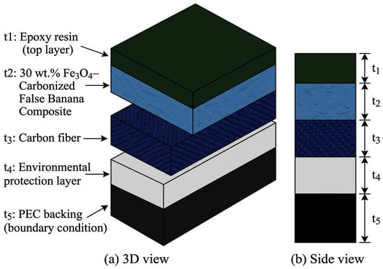
In this study, a four-layer sandwich composite was developed for UAV applications. The top layer is epoxy resin, which acts as an impedance-matching layer to facilitate the penetration of incident EM waves into the absorber. The second layer is a carbonized false banana fiber/Fe3O4 hybrid composite and serves as the primary electromagnetic absorbing medium. Based on mechanisms reported for related biomass-derived carbon and carbon/Fe3O4 absorber systems, the carbonized fiber phase can contribute dielectric and conduction losses, whereas Fe3O4 provides additional magnetic-loss contributions. These mechanisms are therefore considered as physically plausible contributions underlying the adopted effective electromagnetic material model rather than experimentally demonstrated mechanisms of the specific composite. The third layer is made of carbon fiber for structural support and additional electromagnetic damping through conductive loss and reflection control. A thin environmental protection layer is used to improve durability against moisture, temperature, and other environmental factors without negatively affecting the EM performance. In addition, a perfect electric conductor (PEC) backing is applied beneath the composite stack and is modeled in HFSS as an ideal conducting boundary condition. The PEC suppresses electromagnetic transmission through the structure and enhances absorption by forcing repeated internal reflections within the absorber, increasing the probability of dielectric and magnetic energy dissipation. Table 1 summarizes the composition and functional role of each layer.
Table 1.
Electromagnetic absorbing layer represented by the adopted effective electromagnetic properties.
The EM and physical properties adopted in the simulations and optimization are summarized in Table 2. The properties of epoxy resin, carbon fiber, and the environmental protection layer were selected from representative literature sources. For the CFBF/Fe3O4 hybrid absorber, representative effective electromagnetic properties were adopted to establish the material model for the present numerical proof-of-concept study. For properties reported as ranges in Table 2, the arithmetic mean of the lower and upper bounds was used as the effective input value in the HFSS numerical analysis (, , and for the CFBF/Fe3O4 hybrid absorber). The relative permittivity, relative permeability, and loss tangent were treated as effective, isotropic, and frequency-independent properties over the investigated 2–18 GHz range. This approximation was adopted to provide a consistent and computationally tractable material model for the repeated HFSS evaluations required during MOPSO. However, variations in material anisotropy and frequency-dependent electromagnetic properties can modify wave impedance and electrical thickness and may consequently shift resonance frequencies, alter absorption bandwidth, and affect the resulting optimal layer thicknesses. Accordingly, the present model does not explicitly account for the frequency-dependent complex permittivity and permeability of a fabricated CFBF/Fe3O4 composite. The reported electromagnetic performance should therefore be interpreted as numerical predictions within the assumptions of the adopted effective-material model.
Table 2.
Electromagnetic and physical material properties adopted for the HFSS numerical model.
The epoxy resin, carbon-fiber composite, and environmental protection layer are represented as effective material classes rather than specific commercial products. The literature-derived values in Table 2 were adopted as representative inputs for comparable material systems and are not assumed to be universally transferable. Electromagnetic properties can vary with resin formulation, fiber architecture and orientation, fiber volume fraction, coating composition, manufacturing conditions, and frequency. Therefore, material-specific characterization will be required for subsequent experimental implementation of the optimized multilayer design.
3.2. Geometry, Meshing and HFSS Simulation Setup
3.2.1. Geometry
A planar slab panel with dimensions of 100 mm × 100 mm was modeled to represent a modular radar-absorbing material (RAM) panel suitable for integration into UAV external surfaces. The geometry consists of a four-layer composite structure backed by a perfect electric conductor (PEC), as shown in Figure 1. The four physical material layers comprise the epoxy top layer with thickness (), the carbonized false banana fiber/Fe3O4 hybrid composite absorber layer with thickness (), the carbon fiber structural layer with thickness (), and the environmental protection coating with thickness (). A PEC backing is applied beneath the composite stack and is modeled in HFSS as an ideal conducting boundary condition rather than a physical material layer or optimization variable. It is important to note that the PEC backing is labeled as () in Figure 1; however, does not represent a physical layer thickness and is included only to indicate the PEC boundary condition used in the HFSS simulations. Thus, only are treated as physical design variables and contribute to panel thickness and mass.
Figure 1.
Multilayer radar-absorbing composite panel geometry.
The total panel thickness is defined as:
For the present numerical design study, a maximum total thickness of 10 mm was adopted as a study-specific design bound to maintain a compact multilayer configuration suitable for UAV surface integration while providing sufficient design space for the four functional layers. The same total thickness was also adopted for the carbon-fiber reference panel to provide a consistent geometric basis for the subsequent mass comparison. The 10 mm value was therefore treated as an upper design constraint rather than as a universal UAV structural requirement or an optimization target.
3.2.2. Boundary Conditions and Excitation
To evaluate the EM response of the structure, a normally incident plane wave was applied as the primary excitation source. Normal incidence is the reference condition for preliminary RAM assessment. To assess the robustness of the optimized absorber beyond normal incidence, additional simulations were performed at incidence angles of 30° and 45° under both transverse-electric (TE) and transverse-magnetic (TM) polarizations, with 0° incidence used as the reference condition. For TE polarization, the electric field is perpendicular to the plane of incidence, whereas for TM polarization, the magnetic field is perpendicular to the plane of incidence. The same optimized layer geometry, electromagnetic material properties, 2–18 GHz frequency range, meshing strategy, and PEC-backed boundary conditions were retained for all incidence-angle and polarization cases to ensure consistent comparison.
The computational domain around the panel was enclosed using radiation boundaries. These boundaries absorb outgoing electromagnetic waves to approximate free-space propagation. In HFSS, the bottom face of the structure has a PEC boundary condition to prevent EM transmission through the absorber and reflects unabsorbed energy into the structure. This PEC-backed configuration forces the incident EM energy to interact with the CFBF/Fe3O4 hybrid absorber to improve dielectric loss, magnetic loss, and multiple internal reflection mechanisms.
This configuration promotes repeated internal wave interactions and enables the power absorptivity to be determined directly from the reflection coefficient because electromagnetic transmission through the PEC-backed structure is negligible (). The PEC backing acts as an ideal reflector in the HFSS model, physically suppressing EM transmission across the analyzed frequency range. Consistent with the effective-material formulation described in Section 3.1, the nominal HFSS model treated the electromagnetic properties of the constituent layers, including the relative permittivity and relative permeability of the Fe3O4 containing absorber layer, as isotropic and frequency-independent over 2–18 GHz to provide a consistent and computationally tractable basis for the repeated MOPSO evaluations. This assumption represents a modelling approximation rather than an intrinsic description of the actual materials.
3.2.3. Meshing and Solver Settings
For the simulations, ANSYS HFSS v18.1 was used. Adaptive mesh refinement was turned on, typically requiring between five and eight refinement passes. Convergence was defined by a change in of between consecutive passes. The initial mesh was created with a maximum element edge length of divided by 10. Here, is the wavelength at the highest frequency of 18 GHz in the material with the highest relative permittivity in the structure.
To capture steep electromagnetic field gradients, additional localized mesh refinement was applied at material interfaces, particularly at the interfaces between the epoxy matching layer, the carbonized false banana fiber/Fe3O4 hybrid absorber, and the carbon fiber layer, where strong electromagnetic interactions are expected.
Excitation was implemented using a plane-wave launcher. When evaluating periodic tiling configurations, Floquet ports were used. In this work, for the finite planar panel considered, absorbing boundaries were kept. Automatic memory management and parallelization features in HFSS were used to improve solver performance. Mesh-independence validation was performed on representative configurations for numerical reliability.
3.2.4. Post-Processing: Reflection and Absorption Metrics
HFSS can compute the reflection coefficient () at each frequency in the sweep. In this work, power absorptivity () and the reflection coefficient () are the main indicators of EM performance, whereas reflection loss () is used for comparison with existing literature. For the present PEC-backed configuration, electromagnetic transmission is negligible because the PEC prevents power transmission through the structure. Therefore, absorbed power is calculated as:
Accordingly, A(f) is power absorptivity (absorption efficiency), not reflectance. The power reflectance is given by |, whereas for the present PEC-backed structure.
The reflection loss (RL), expressed in decibels, can be calculated as [45]:
where is the magnitude of the reflection coefficient.
Broadband performance is evaluated using both the frequency-averaged absorptivity and the effective absorption bandwidth. The frequency-averaged absorptivity over a sampled frequency interval is calculated as the arithmetic mean of at all frequency points within that interval. The effective absorption bandwidth is defined as the cumulative frequency interval over which the reflection loss satisfies dB. The −10 dB criterion corresponds to:
which indicates that the structure absorbs at least 90% of the incident electromagnetic energy. Thus, the reported average absorption values represent frequency-averaged power absorptivity and should not be interpreted as reflectance or effective absorption bandwidth. The simulated absorption performance is consistent with the combined electromagnetic attenuation mechanisms reported for related carbon/Fe3O4 absorber systems, including dielectric and conduction losses, magnetic-loss contributions, and internal reflections. However, the individual contributions of these mechanisms were not experimentally resolved for the specific CFBF/Fe3O4 composite considered in the present numerical study.
3.3. Problem Formulation for Multi-Objective Optimization
3.3.1. Design Variables and Bounds
The optimization of the multilayer radar-absorbing composite considers the thickness of each of the four layers as continuous design variables. The layer sequence was kept fixed as epoxy/CFBF-Fe3O4/carbon fiber/environmental protection throughout the optimization. This sequence was selected according to the functional role assigned to each constituent: the epoxy top layer provides impedance matching at the incident-wave side, the CFBF/Fe3O4 layer acts as the primary lossy absorber, the carbon-fiber layer provides structural support and secondary electromagnetic attenuation, and the outer protection layer provides environmental protection. Accordingly, the present MOPSO formulation was intentionally restricted to thickness optimization within this prescribed functional architecture rather than simultaneous material-order and thickness optimization. These layer thicknesses are constrained considering the manufacturability and mechanical requirements, as shown in Table 3.
Table 3.
Design variables and bounds.
3.3.2. Objective Functions
In this work, three conflicting objectives are considered: maximizing broadband EM absorption, minimizing structural mass, and minimizing total thickness. Because the absorber is backed by a PEC, electromagnetic transmission is negligible (); therefore, absorption performance is evaluated directly from the reflection coefficient obtained from HFSS. Here, absorption refers to power absorptivity, , rather than reflectance, . For the PEC-backed configuration, and because transmission is negligible. The first objective is mathematically expressed as:
where is the number of frequency points () sampled across the 2–18 GHz band, and is the reflection coefficient obtained from HFSS for the given layer-thickness configuration () at frequency (). Most optimization frameworks are formulated as minimization problems; therefore, the implementation minimizes (), which maximizes ().
The frequency-averaged absorptivity was selected as the electromagnetic optimization objective because it provides a continuous measure of absorption performance over the entire 2–18 GHz frequency range. In contrast, the effective absorption bandwidth is a threshold-based metric, defined in this study as the cumulative frequency interval over which , equivalently dB for the PEC-backed configuration. Therefore, effective absorption bandwidth was used as a complementary performance metric rather than as an independent optimization objective. This formulation enables the optimization to improve the overall absorption response across the investigated frequency range while simultaneously minimizing structural mass and total thickness.
Angular and polarization robustness were evaluated separately for the selected optimized configuration as a post-optimization assessment and were not included as additional objective functions in the MOPSO formulation. Specifically, the selected configuration was subsequently evaluated under TE and TM polarizations at incidence angles of 0°, 30°, and 45°, as described in Section 3.2.2.
The second objective is to minimize the structural mass of the composite panel. Using SI units, the panel mass () is calculated as:
where is the density of layer , is its thickness, is the cross-sectional area of the panel.
The third objective is to minimize the total panel thickness (), expressed as:
These three objectives define the vector optimization problem, as:
subject to the constraints described in Section 3.3.3
The three objective functions were not combined into a single weighted-sum fitness function. Instead, MOPSO simultaneously evaluates the objective vector in Equation (14) using Pareto dominance, whereby a solution is retained as non-dominated when no other feasible solution improves one objective without degrading at least one of the others. Therefore, no predefined weighting coefficients were assigned to electromagnetic absorption, structural mass, or total thickness. The resulting non-dominated solutions are stored in the external archive and collectively constitute the approximate Pareto-optimal set used for subsequent design selection [37,46,47].
3.3.3. Constraints
In this study, the optimization is subject to certain practical constraints. First, a reflection-loss coverage requirement is enforced in the high-frequency band, such that:
This condition is equivalent to requiring a RL of at least across the Ku-band and corresponds to a minimum absorption efficiency of approximately 90% for the PEC-backed absorber configuration. All electromagnetic constraints are implemented using , because the PEC backing eliminates transmission losses and ensures that the absorption performance is governed by reflection suppression and EM attenuation within the multilayer composite.
The total thickness of the panel is also constrained to satisfy:
and all individual layer thicknesses remain within the bounds specified in Table 3.
3.4. Implementation of MOPSO Algorithm
3.4.1. Why MOPSO
In this study, MOPSO was chosen because it searches continuous and nonconvex design spaces. MOPSO also provides a set of Pareto-optimal, non-dominated solutions. This ability is valuable for engineering problems that involve balancing multiple conflicting objectives [46,47].
3.4.2. Algorithmic Parameters
The MOPSO parameters used in this study are summarized in Table 4.
Table 4.
MOPSO algorithm parameters.
3.4.3. Optimization Workflow
The MOPSO-based optimization follows a structured sequence of steps:
- Initialization: The swarm starts by randomly generating particles () within the allowable thickness bounds of the physical composite layers.

- Fitness Evaluation: For each particle configuration , the HFSS model with parameterized layer geometry is generated. A frequency sweep from 2 to 18 GHz is performed, and ()) is extracted. The average power absorption (), panel mass (), and total thickness () are computed for each particle. These quantities correspond directly to the three objective functions defined in Equations (11)–(13); they are evaluated as a vector rather than combined into a scalar weighted fitness value. Pareto dominance is subsequently used to rank the candidate solutions and update the external archive.
- Archive Update: Non-dominated solutions are added to the external archive. When the archive exceeds its capacity, crowding-distance pruning is applied to maintain solution diversity.
- Velocity and Position Update: Particle velocities are updated according to the standard PSO equation:
Boundary checks are applied, and any violation triggers a boundary reset, setting the particle to the nearest allowable value and adjusting the velocity.
- 5.
- Constraint Handling: Particles that violate reflection-loss or thickness constraints are marked as infeasible. Infeasible solutions are either penalized in the fitness function or redirected toward feasible values. Preference is always given to feasible archive members when selecting global guides.
- 6.
- Iteration and Convergence: The evaluation, archive update, and velocity/position update steps are repeated until the Pareto front stabilizes. Convergence is verified by monitoring the variation in objective function values over successive iterations.
- 7.
- Selection and Analysis: Upon convergence, the external archive contains the Pareto-optimal set of layer thickness configurations. Candidate solutions are selected based on UAV-specific priorities, such as minimizing mass while maintaining adequate absorption or achieving minimum total thickness while satisfying (or ) in the 12 to 18 GHz Ku-band range. Convergence is additionally verified by observing the stabilization of objective function trends across iterations. The selected Pareto solutions undergo detailed HFSS re-evaluation using a tighter mesh and adaptive settings. Where applicable, they are further analyzed under oblique incidence conditions to verify the angular stability of absorption performance.
3.4.4. Computational Considerations and Surrogate Modeling
Full HFSS simulations for every particle evaluation are computationally expensive. To mitigate this, a two-stage evaluation strategy is used. Early iterations employ a coarse HFSS setup with reduced frequency sampling and relaxed mesh settings. Final candidate solutions are then re-evaluated with full solver precision. Data from HFSS runs can train surrogate models to predict and speed up particle evaluation. Surrogates are iteratively validated and retrained using active learning to prevent bias in the optimization process.
3.4.5. Convergence Behavior and Sensitivity Considerations
To provide a more rigorous assessment of algorithm performance, the convergence behavior of MOPSO is evaluated based on the evolution of objective function values and Pareto-front stability over iterations. The convergence is confirmed when successive iterations exhibit negligible changes in the Pareto front and objective metrics stabilize.
Furthermore, the sensitivity of the optimization process to algorithm parameters (such as inertia weight, cognitive constant, and swarm size) is evaluated qualitatively. The selected configuration provides a balance between exploration and exploitation without leading to premature convergence.
3.4.6. Pseudocode of the MOPSO
The pseudocode of the MOPSO for multilayer RAM optimization employed in this study is presented in Algorithm 1.
| Algorithm 1. Pseudocode for MOPSO-Based Optimization of Multilayer RAM | |
| Function: MOPSO_RadarAbsorber(bounds, P, MaxIter) | |
| Input: Bounds for , , , ; Population size , Maximum iterations MaxIter Output: External archive (Pareto set) | |
 | |
4. Results and Discussion
4.1. Optimization Results and Pareto Front Analysis
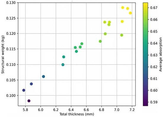
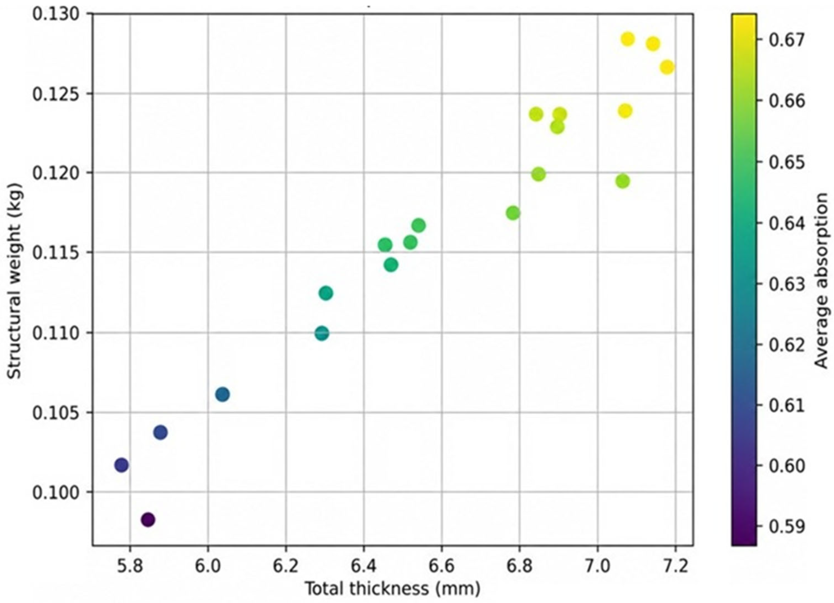
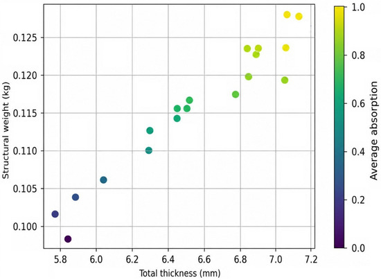
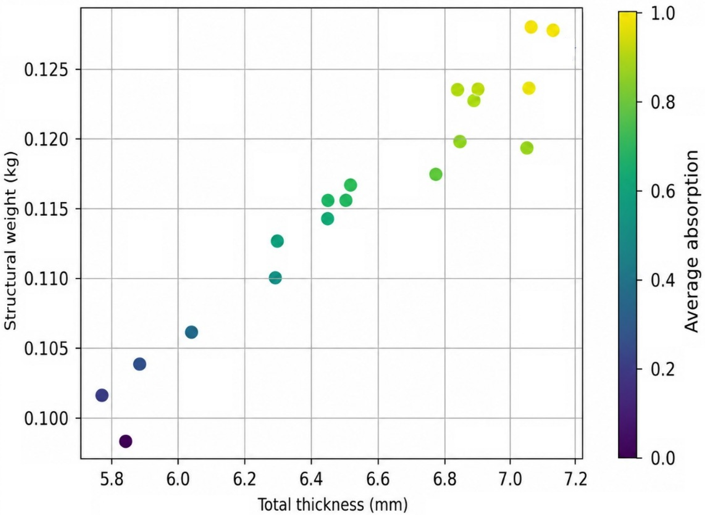
The MOPSO algorithm operated with 40 particles, 300 iterations, and an archive size of 50, incorporating dynamic inertia weighting from 0.9 to 0.4 and cognitive/social coefficients (). The optimization process created a Pareto archive containing 50 non-dominated solutions after 300 iterations. Because no objective weighting coefficients were used, the archived solutions represent alternative trade-offs among electromagnetic absorption, structural mass, and total thickness. A compromise solution was selected from the Pareto-optimal set and subsequently adjusted considering the practical layer-thickness and manufacturability requirements of the multilayer configuration. Figure 2 shows the structural weight versus total thickness for all Pareto-optimal solutions. The color scale represents the corresponding average absorption.
Figure 2.
Pareto-optimal trade-offs among structural weight, total thickness, and average electromagnetic absorption obtained using MOPSO.
As shown in Figure 2, the Pareto-optimal solutions result in the expected trade-off between structural weight, total thickness, and EM absorption. The continuous optimization solutions are distributed over a total thickness range of approximately 5.9 mm to 7.2 mm, with corresponding structural weights ranging from approximately 0.10 kg to 0.13 kg. Within this Pareto-optimal set, solutions with greater thickness and mass generally provide higher average absorption, while progressively smaller gains in electromagnetic performance are obtained toward the upper end of the Pareto set. A compromise solution was therefore selected to balance these three competing objectives rather than prioritizing any single objective through an assigned weighting coefficient.
The selected Pareto compromise represents a continuous solution obtained directly from the MOPSO Pareto archive. Because the continuous optimization produced layer thicknesses that were not retained directly as the final practical dimensions, the selected compromise was subsequently adjusted to practical layer thicknesses for the four-layer architecture. This post-optimization adjustment produced the final 2/5/2/1 mm configuration with a total thickness of 10 mm, as summarized in Table 5. Accordingly, the final configuration represents a practical configuration derived from the selected Pareto compromise rather than a directly generated Pareto-optimal solution. The adjustment was made to provide practical layer dimensions while satisfying the study-specific 10 mm upper design bound and preserving the functional roles of the four constituent layers. The electromagnetic and structural performance reported for the final configuration was evaluated after this adjustment, while the continuous Pareto-stage and final configuration results are distinguished in the subsequent performance analysis.
Table 5.
Optimal layer thicknesses.
As seen in Table 5, the carbonized false banana fiber/Fe3O4 absorber layer constitutes the largest portion of the multilayer structure (50% of the total thickness), demonstrating its dominant role in electromagnetic wave attenuation. The epoxy impedance matching layer and the carbon fiber structural layer each contribute 20% of the total thickness, where the former minimizes impedance mismatch at the air-material interface, and the latter provides the required mechanical stiffness for structural applications. The environmental coating accounts for the remaining 10% of the total thickness, serving primarily as a protective layer against environmental degradation.
4.2. Electromagnetic Absorption Performance
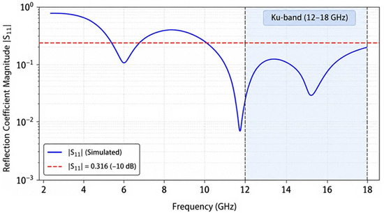
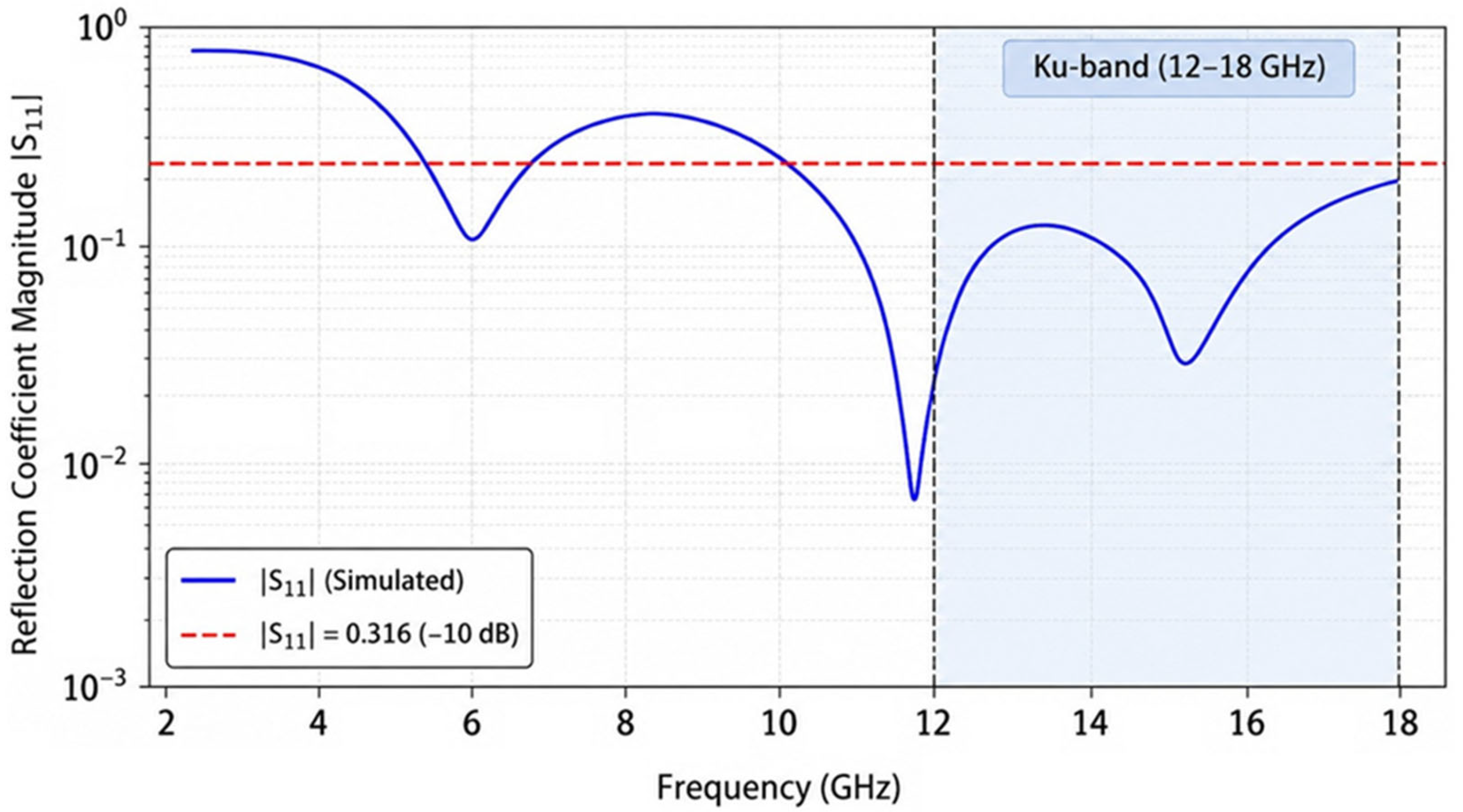
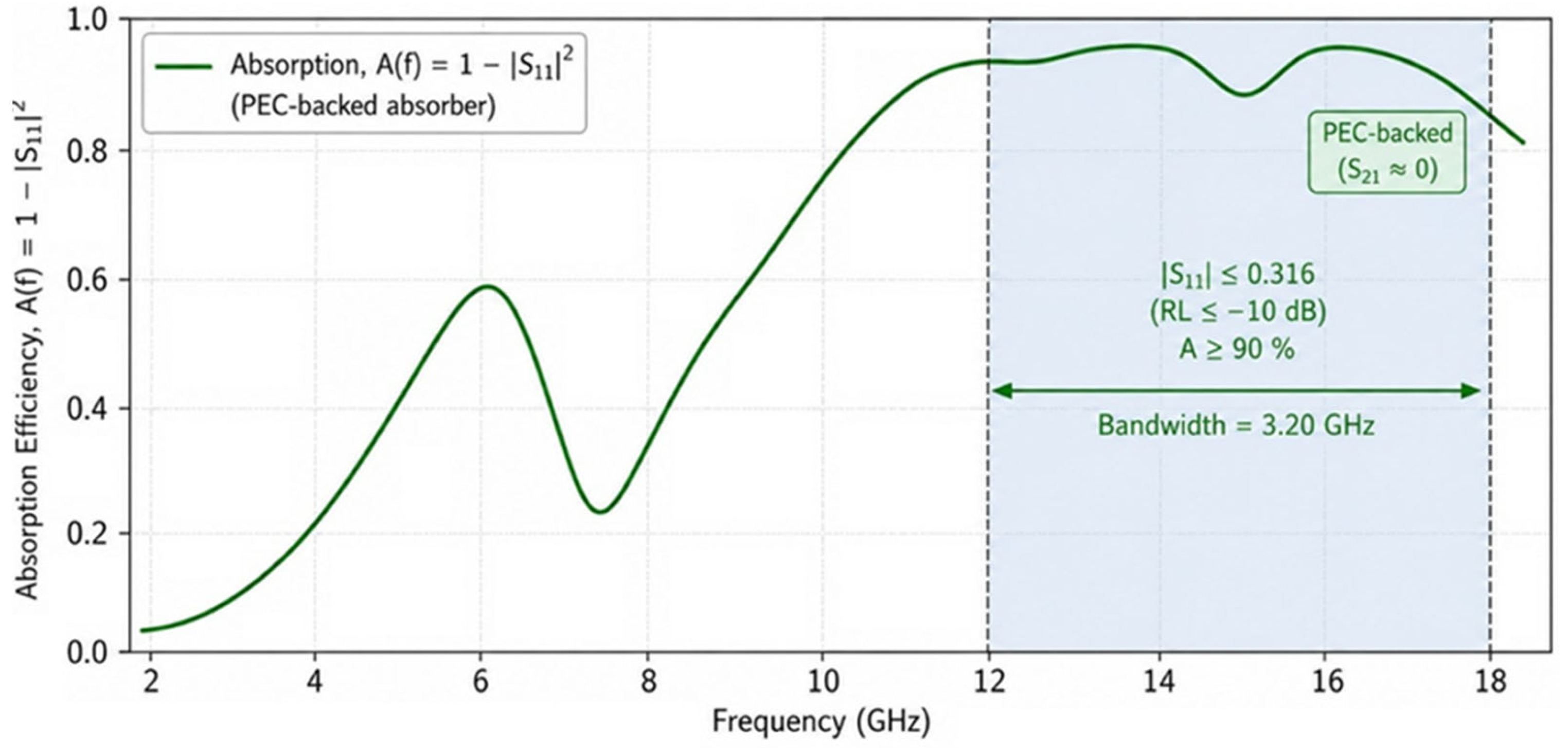
The EM performance of the optimized four-layer composite was analyzed using full-wave electromagnetic simulations in ANSYS HFSS. The resulting across the 2–18 GHz frequency range is shown in Figure 3. The simulated response reveals broadband EM attenuation over the investigated frequency range, with improved absorption performance concentrated within the Ku-band (12–18 GHz). Since the absorber is backed by a PEC, EM transmission is negligible (). The optimized structure achieved an average Ku-band absorption of 0.8289 with an effective absorption bandwidth () of approximately 3.2 GHz.
Figure 3.
Simulated reflection-coefficient magnitude of the optimized PEC-backed multilayer absorber over the 2–18 GHz frequency range.
Figure 3 indicates multiple resonance modes generated by the optimized multilayer structure. The minimum reflection coefficient obtained from the optimization was , corresponding to a minimum RL of −32.75 dB. Under the PEC-backed assumption, this reflection minimum corresponds to an absorption efficiency of 99.95%. This also further shows almost complete attenuation of the incident electromagnetic energy at the resonance frequency. Additional resonance dips observed throughout the operating frequency range contribute to the broadband absorption characteristics of the optimized absorber.
The consistently low reflection levels across a wide frequency range show effective impedance matching between free space and the multilayer absorber. It maintained a broad low-reflection response with a minimum RL of −32.75 dB and an average Ku-band absorption of 82.89%. This performance validates the effectiveness of the optimized layer configuration in achieving improved electromagnetic absorption together with reduced structural weight and panel thickness.
The presence of multiple resonance minima suggests that EM attenuation results from a combination of dielectric loss mechanisms within the carbonized false banana fiber layer and interference effects due to the multilayer architecture. The carbonized false banana fiber/Fe3O4 absorber layer serves as the primary lossy medium. Whereas the epoxy impedance matching layer reduces the impedance mismatch between free space and the absorber surface. The carbon fiber structural layer and PEC backing promote multiple internal reflections, increasing the effective propagation path of electromagnetic waves within the multilayer structure and enhancing energy dissipation. The observed broadband response is therefore attributed to the combined effects of impedance matching, dielectric loss, multilayer interference, and multiple-reflection mechanisms.
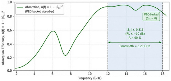
As shown in Figure 4, the corresponding power absorption profile supports the broadband absorption capability of the optimized design. With the absorber backed by a PEC, EM transmission remains negligible (). The absorption efficiency is determined directly from the reflection coefficient as . The simulated absorption spectrum reveals broadband absorption behaviour throughout the investigated frequency range, with the highest absorption occurring near the resonance frequencies identified in Figure 3.
Figure 4.
Simulated power absorptivity of the optimized PEC-backed multilayer absorber over the 2–18 GHz frequency range.
The optimized multilayer absorber achieved an effective absorption bandwidth of approximately 3.2 GHz for . In addition, the average power absorptivity over the entire 2–18 GHz frequency range reached 0.6756. The average Ku-band power absorptivity was 0.8289. These results show that the optimized multilayer structure provides substantial broadband EM attenuation while maintaining reduced structural weight and thickness.
Compared with the baseline carbon fiber panel, the optimized multilayer design increased the average absorption from 0.5334 to 0.6756 and improved the Ku-band absorption from 0.7064 to 0.8289. The minimum reflection coefficient decreased from 0.0591 to 0.0230, corresponding to an improvement in minimum RL from −24.57 dB to −32.75 dB. These improvements confirm the effectiveness of incorporating the carbonized false banana fiber/Fe3O4 absorbing layer together with the optimized multilayer architecture.
To further evaluate the practical electromagnetic robustness of the optimized 2/5/2/1 mm multilayer configuration, the absorption response was examined under both transverse-electric (TE) and transverse-magnetic (TM) polarizations at incidence angles of 0°, 30°, and 45°. At normal incidence, the response provides the common reference condition, whereas TE and TM responses were evaluated separately at oblique incidence because their effective wave impedances and propagation conditions differ with increasing incidence angle.
The oblique-incidence simulations showed that the principal broadband absorption characteristics of the optimized multilayer absorber were retained under both TE and TM polarizations up to 45°. With increasing incidence angle, variations in resonance position and absorption magnitude were observed due to changes in impedance matching and phase accumulation through the multilayer structure. The TE and TM responses also showed increasing differentiation at oblique incidence because of their different electromagnetic boundary conditions. Nevertheless, the principal absorption characteristics remained present under the investigated incidence conditions, indicating that the optimized configuration is not restricted to normal-incidence operation.
The angular and polarization analyses were performed as post-optimization robustness evaluations of the selected multilayer configuration; therefore, the layer thicknesses were not re-optimized independently for each TE and TM incidence condition. The results demonstrate the angular and polarization robustness of the selected design within the investigated 0–45° incidence range. A broader angular range and polarization-dependent optimization may be considered in future work to further improve oblique-incidence performance.
4.3. Structural Weight and Thickness Evaluation
The final four-layer configuration has a total thickness of 10.00 mm, consistent with the study-specific upper design bound. For a consistent comparison, the proposed multilayer panel and the baseline carbon-fiber (CF) panel were evaluated using the same 100 × 100 mm footprint and the same total thickness of 10.00 mm. The baseline was defined as a monolithic carbon-fiber reference panel; therefore, the comparison was performed on an equivalent geometric basis, and the difference in mass results from the different material compositions of the two configurations. With the selected material densities, the optimized multilayer composite has a mass of 0.172500 kg, whereas the baseline carbon-fiber panel has a mass of 0.174990 kg, corresponding to a reduction of approximately 1.42%. This mass reduction is modest because the baseline carbon-fiber panel is itself a lightweight structural material. Therefore, the 1.42% reduction should not be interpreted as a major standalone light weighting advantage. Rather, the principal benefit of the proposed configuration is that improved electromagnetic functionality is achieved while maintaining the same footprint and overall thickness and without introducing an additional mass penalty relative to the carbon-fiber reference panel.
Figure 5 shows the distribution of Pareto-optimal solutions in terms of structural weight, total thickness, and average electromagnetic absorption. The Pareto front shows the trade-off between lightweight design and absorption performance obtained from the continuous optimization process. The optimized solutions are distributed over a thickness range of 5.9–7.2 mm, corresponding to structural weights between 0.10 and 0.13 kg. The average absorption increases from approximately 0.59 to 0.68 as both thickness and structural weight increase. This trend indicates that improved EM performance requires additional absorbing material. These Pareto solutions are ideal mathematical candidates generated by the optimization algorithm. Therefore, the selected Pareto compromise was subsequently adjusted by applying practical layer-thickness constraints to obtain the final 10 mm multilayer configuration. The resulting 2/5/2/1 mm configuration has a calculated mass of 0.1725 kg and HFSS-predicted average absorptivities of 0.6756 over 2–18 GHz and 0.8289 over the Ku-band. These results distinguish the performance ranges of the continuous Pareto-optimal solutions from the performance of the final multilayer configuration.
Figure 5.
Pareto-optimal distribution of structural weight, total thickness, and average electromagnetic absorption.
In Figure 5, the Pareto-optimal solutions show a positive relationship among total thickness, structural weight, and EM absorption performance. The selected Pareto compromise represents a continuous solution obtained from the Pareto archive and was subsequently adjusted to the practical 2/5/2/1 mm configuration considering layer-thickness and manufacturability requirements. The resulting configuration provides a total thickness of 10.0 mm, a structural mass of approximately 0.1725 kg, and improved EM absorption compared with the baseline carbon-fiber panel. The Pareto distribution also indicates that increasing thickness improves absorption performance, although the rate of improvement gradually decreases for thicker configurations. The selected Pareto compromise and its corresponding final configuration therefore represent a balance among electromagnetic performance, structural mass, and manufacturing feasibility rather than a design selected primarily for maximum mass reduction.
Table 6 presents the main performance metrics of the optimized multilayer RAM structure. The optimized design results in an average absorption of 0.6756 over the 2–18 GHz frequency range and an average Ku-band absorption of 0.8289, together with a minimum reflection coefficient of 0.0230 (corresponding to approximately 99.95% absorption at resonance) and an RL of −32.75 dB. The proposed configuration improves electromagnetic performance while retaining the same 100 × 100 mm footprint and 10 mm overall thickness as the baseline carbon-fiber panel. The associated 1.42% mass reduction is therefore considered a secondary benefit rather than the primary performance advantage. These results show that the MOPSO-based optimization framework identified a multilayer configuration that balances the modeled electromagnetic absorption, mass, and thickness objectives within the adopted UAV-oriented design constraints.
Table 6.
Performance metrics of the final four-layer RAM configuration.
4.4. Layer-Wise Functional Contribution
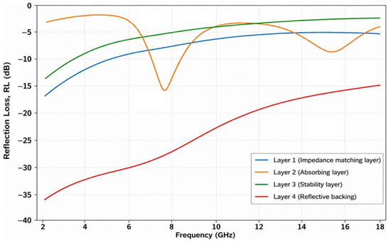
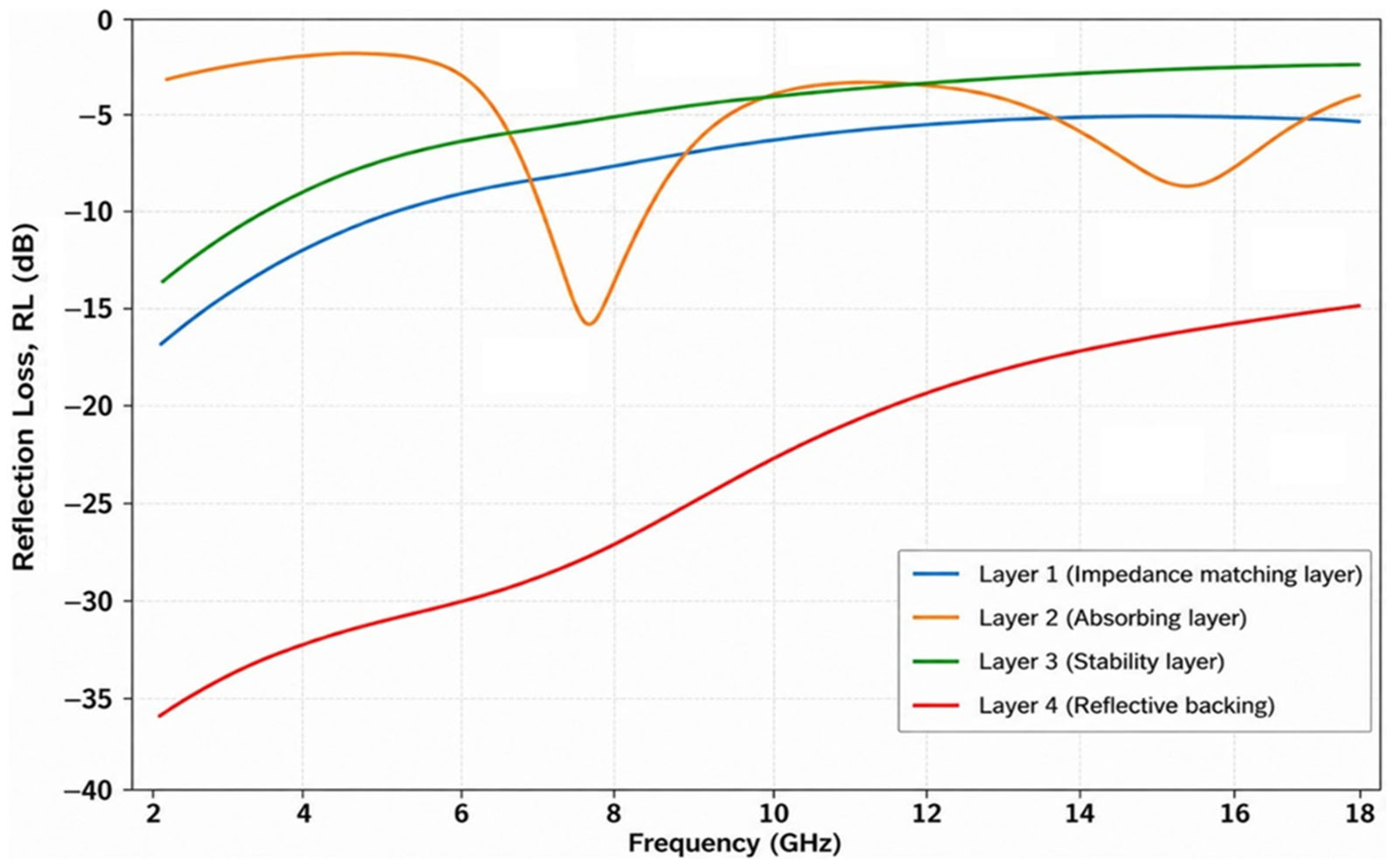
Figure 6 shows the contribution of individual layers to broadband EM absorption. The epoxy impedance matching layer with a thickness of 2.0 mm improves the transition of incident electromagnetic waves from free space into the multilayer structure by reducing impedance mismatch at the air-absorber interface.
Figure 6.
Contribution of individual layers to broadband EM absorption.
As shown in Figure 6, the RL performance of each layer was evaluated independently over the 2–18 GHz frequency range. The negative RL values indicate reduced reflection coefficient magnitude and improved electromagnetic attenuation. The epoxy impedance matching layer shows a gradual reduction in RL with increasing frequency, confirming its contribution to improving impedance matching. The carbonized false banana fiber/Fe3O4 absorber layer (5.0 mm) results in the strongest absorbing contribution among the individual layers. This behaviour is attributed to its high dielectric loss capability, resulting from the combined effects of carbonization, Fe3O4 magnetic inclusions, and the relatively high loss tangent (tan δ = 0.20). The absorber layer promotes dielectric dissipation and converts incident electromagnetic energy into heat through polarization losses and magnetic loss mechanisms. The 2.0 mm carbon fiber structural layer provides mechanical reinforcement while also contributing to electromagnetic attenuation through reflection and internal electromagnetic interactions. The conductive carbon fiber layer can help in enhancing reflection effects within the PEC-backed multilayer architecture. The 1.0 mm environmental coating layer provides external protection against moisture, mechanical damage, and environmental degradation.
The broadband absorption performance of the optimized multilayer structure results from the combined effects of several physical processes. The epoxy layer improves impedance matching at the air-absorber interface. The carbonized false banana fiber/Fe3O4 absorber layer dissipates EM energy through dielectric and magnetic losses. The carbon fiber layer improves conductive interactions, whereas multiple internal reflections occur between adjacent interfaces and the PEC backing. These processes increase the effective propagation path of electromagnetic waves within the absorber. As a result, energy dissipation is enhanced across the 2–18 GHz frequency range.
4.5. Comparative Performance Analysis
To evaluate electromagnetic performance and structural efficiency on a consistent geometric basis, the optimized four-layer radar-absorbing composite was compared with a monolithic carbon-fiber (CF) reference panel having the same 100 × 100 mm footprint and the same total thickness of 10 mm. The baseline therefore represents an equal-volume geometric reference, allowing the effects of the proposed multilayer material architecture on mass and electromagnetic performance to be compared directly. As seen in Table 7, the results demonstrate the advantages of integrating the carbonized false banana fiber/Fe3O4 absorbing layer with the optimized multilayer architecture. Although both structures maintain the same overall thickness of 10 mm, the optimized multilayer composite provides improved electromagnetic attenuation characteristics compared with the conventional carbon fiber panel. The optimized composite achieves an average absorption of 0.6756 over the 2–18 GHz frequency range and an average Ku-band absorption of 0.8289, whereas the baseline carbon fiber panel achieves only 0.5334 and 0.7064, respectively. Furthermore, the optimized design reduces the minimum reflection coefficient from 0.0591 for the baseline carbon fiber panel to 0.0230, corresponding to an improvement in minimum RL from −24.57 dB to −32.75 dB. These results confirm the effectiveness of the multilayer design in improving electromagnetic wave attenuation.
Table 7.
Performance comparison of the optimized composite versus baseline and literature.
As shown in Table 7, the optimized multilayer RAM panel provides higher electromagnetic absorption performance than the baseline carbon-fiber structure while maintaining the same overall thickness and footprint. The minimum absorption corresponding to the resonance condition reaches 0.9995 (99.95%) due to the minimum reflection coefficient of 0.0230. It is important to note that this 99.95% absorption value is the peak absorption occurring at the resonance frequency. The reported average Ku-band absorption of 82.89% represents the frequency-averaged power absorptivity over the 12–18 GHz operational range. In comparison, the baseline carbon-fiber panel results in a lower RL and reduced absorption capability.
The proposed multilayer design provides a modest mass reduction of 1.42% compared with the equal-footprint, equal-thickness monolithic carbon-fiber reference panel. This limited reduction is expected because the reference panel is itself a lightweight structural material. Therefore, mass reduction should not be regarded as the principal advantage of the proposed configuration. Instead, the main benefit is the simultaneous improvement in electromagnetic absorption while maintaining the same geometric envelope and avoiding an increase in panel mass.
The optimized RAM panel also shows improved Ku-band absorption bandwidth. This achieves an effective absorption bandwidth of 3.2 GHz for absorption values above 90%. The angular stability analysis confirms that the multilayer structure maintains relatively stable absorption behaviour under incidence angles of 0°, 30°, and 45°, indicating robustness for practical UAV operating conditions.
However, the baseline carbon fiber used in this study is not an optimized electromagnetic absorber reference. The conventional carbon fiber panel can provide structural reinforcement and does not add impedance-matching layers, dielectric-loss materials, or magnetic absorbing components. In contrast, to achieve multifunctional performance, the proposed multilayer architecture combines an epoxy impedance-matching layer, carbonized false banana fiber/Fe3O4 absorber layer, carbon fiber structural layer, and environmental coating.
Although some literature RAM configurations in Table 7 show higher broadband absorption and larger reported mass reductions, the principal contribution of the present design is the integration of a biomass-derived CFBF/Fe3O4 absorbing layer with a multilayer optimization framework that improves electromagnetic performance relative to the equal-footprint, equal-thickness carbon-fiber reference without increasing panel mass. The use of a biomass-derived constituent provides a potential sustainability advantage; however, environmental benefit, manufacturability, structural performance, and durability were not quantitatively evaluated in the present numerical study. Therefore, the proposed configuration should be regarded as a numerical proof-of-concept for a candidate UAV-oriented RAM architecture rather than as a validated UAV structural panel. The predicted electromagnetic performance is also conditional on the ideal PEC-backed HFSS model and the adopted effective material properties.
5. Conclusions and Future Work
In this work, a multi-objective optimization framework was developed for designing a lightweight radar-absorbing multilayer composite for stealth-enabled UAV applications using a carbonized false banana fiber/Fe3O4 hybrid absorber. Full-wave electromagnetic simulations were integrated with the MOPSO algorithm to optimize electromagnetic absorption, structural weight, and panel thickness constraints.
The optimized four-layer RAM panel showed improved electromagnetic attenuation performance. The final engineering configuration consisted of a 2/5/2/1 mm multilayer arrangement: a 2.0 mm epoxy impedance matching layer, 5.0 mm carbonized false banana fiber/Fe3O4 absorber layer, 2.0 mm carbon fiber structural layer, and 1.0 mm environmental coating. The optimized structure achieved an average absorption of 0.6756 over the 2–18 GHz frequency range and 0.8289 in the Ku-band (12–18 GHz), with an effective absorption bandwidth of approximately 3.2 GHz for absorption values above 90%. A minimum reflection coefficient of 0.0230 (corresponding to 99.95% absorption at resonance) was obtained near the resonance frequency, resulting in a minimum RL of −32.75 dB. These results confirm localized attenuation capability and broadband electromagnetic suppression within the investigated frequency range.
From the structural perspective, the optimized multilayer panel achieved a total weight of 0.1725 kg, compared with 0.1750 kg for the baseline carbon fiber panel. This resulted in a weight reduction of 1.42%, maintaining the same 10 mm thickness. The layer-wise analysis confirmed that the carbonized false banana fiber/Fe3O4 layer provides the dominant EM attenuation contribution through the adopted dielectric and magnetic material response. The epoxy layer is incorporated to support impedance matching, the carbon-fiber layer is incorporated to provide the structural function of the multilayer architecture, and the environmental coating is included for protection against external exposure. However, mechanical performance, environmental durability, and sustainability were not quantitatively evaluated in the present study. Accordingly, the results demonstrate the electromagnetic potential of incorporating a biomass-derived CFBF/Fe3O4 absorber into a UAV-oriented multilayer RAM concept rather than validating the complete structural or environmental performance of a UAV panel.
The present study is limited by the use of effective, isotropic, and frequency-independent electromagnetic properties for the constituent materials, particularly the CFBF/Fe3O4 hybrid absorber and carbon-fiber layer; consequently, material dispersion and anisotropy could shift the predicted resonance frequencies, absorption bandwidth, and resulting optimized layer thicknesses. To address these limitations, future work will experimentally characterize the frequency-dependent complex permittivity and permeability of the fabricated CFBF/Fe3O4 composite over the 2–18 GHz frequency range and incorporate the measured properties into the HFSS model. The optimized 2/5/2/1 mm multilayer configuration will also be used as the target layup for composite fabrication, followed by experimental measurement of its reflection loss and electromagnetic absorption performance for direct comparison with the HFSS predictions. Future investigations will also incorporate more realistic interfacial modeling to improve numerical accuracy. The absence of experimental validation of the optimized multilayer configuration is also a limitation of the present numerical study. Accordingly, the optimized 2/5/2/1 mm multilayer configuration will be used as the target layup for composite fabrication, followed by experimental measurement of its reflection loss and electromagnetic absorption performance for comparison with the HFSS predictions. The present optimization was also limited to layer-thickness variation within the fixed epoxy/CFBF/Fe3O4/carbon fiber/environmental-protection sequence; therefore, future work will investigate simultaneous layer-sequence and thickness optimization to determine whether alternative stacking arrangements can further improve broadband electromagnetic absorption and effective absorption bandwidth. Furthermore, future research will consider radar cross-section reduction analysis, mechanical performance evaluation, environmental durability testing, and quantitative sustainability assessment, together with structural-electromagnetic integrated optimization, to assess the practical applicability of the proposed multilayer RAM concept for UAV stealth platforms.
Author Contributions
Conceptualization, M.A.G.; methodology, M.A.G.; software, M.A.G.; validation, B.S.Y. and G.T.C.; formal analysis, M.A.G.; investigation, M.A.G.; writing—original draft preparation, M.A.G.; writing—review and editing, B.S.Y. and G.T.C.; visualization, B.S.Y. and G.T.C.; supervision, B.S.Y. All authors have read and agreed to the published version of the manuscript.
Funding
This research received no external funding.
Data Availability Statement
The raw data supporting the conclusions of this article will be made available by the authors on request.
Acknowledgments
The authors acknowledge the support provided by Addis Ababa Science and Technology University, Ethiopia and the Space Science and Geospatial Institute, Ethiopia, for providing the computational resources and equipment used in this study.
Conflicts of Interest
The authors declare no conflicts of interest.
References
- Yan, Y.; Yi, D.; Lu, H.; Gao, L. Control and Applications of Intelligent Unmanned Aerial Vehicles. Electronics 2025, 14, 375. [Google Scholar] [CrossRef] [Scilit]
- Nam, Y.W.; Choi, J.H.; Jang, M.S.; Lee, W.J.; Kim, C.G. Radar-absorbing structure with nickel-coated glass fabric and its application to a wing airfoil model. Compos. Struct. 2017, 180, 507–512. [Google Scholar] [CrossRef] [Scilit]
- Tan, X.; Gu, W.; Tao, Z.; Chen, X.; Li, S.; Xia, A.; Ji, G. Carbon-based Materials for Radar-infrared Compatible Stealth Technology. Chem. Eng. J. 2025, 507, 160168. [Google Scholar] [CrossRef] [Scilit]
- Chen, W.; Zheng, X.; He, X.; Su, Y.; Wang, J.; Yang, J.; Chen, S.; Zheng, Z. Achieving full effective microwave absorption in X band by double-layered design of glass fiber epoxy composites containing MWCNTs and Fe3O4 NPs. Polym. Test. 2020, 86, 106448. [Google Scholar] [CrossRef] [Scilit]
- Bian, P.; Yu, Q.; Zhan, B.; Guo, B.; Gao, P.; Hong, L.; Yang, Y.; Wang, C. Broadband electromagnetic wave absorption cement-based composite using foam-loaded KH550@Fe3O4 nanoparticles. Constr. Build. Mater. 2024, 449, 138324. [Google Scholar] [CrossRef] [Scilit]
- Li, X.; Gong, R.; Nie, Y.; Zhao, Z.; He, H. Electromagnetic properties of Fe55Ni45 fiber fabricated by magnetic-field-induced thermal decomposition. Mater. Chem. Phys. 2005, 94, 408–411. [Google Scholar] [CrossRef] [Scilit]
- Feng, Y.B.; Qiu, T.; Shen, C.Y.; Li, X.Y. Electromagnetic and absorption properties of carbonyl iron/rubber radar absorbing materials. IEEE Trans. Magn. 2006, 42, 363–368. [Google Scholar] [CrossRef] [Scilit]
- Ahmad, A.F.; Abbas, Z.; Obaiys, S.J.; Zainuddin, M.F. Effect of untreated fiber loading on the thermal, mechanical, dielectric, and microwave absorption properties of polycaprolactone reinforced with oil palm empty fruit bunch biocomposites. Polym. Compos. 2018, 39, E1778–E1787. [Google Scholar] [CrossRef] [Scilit]
- Kumar, R.; Gunjal, J.; Chauhan, S. Effect of carbonization temperature on properties of natural fiber and charcoal filled hybrid polymer composite. Compos. Part B Eng. 2021, 217, 108846. [Google Scholar] [CrossRef] [Scilit]
- Pattanayak, S.S.; Laskar, S.H.; Sahoo, S. Design from waste: An eco-efficient microwave absorber using dried banana leaves and charcoal based composite. J. Mater. Sci. Mater. Electron. 2022, 33, 13398–13407. [Google Scholar] [CrossRef] [Scilit]
- Rajamanikandan, T.; Banumathi, S.; Arul, P.; Shankar, R. Dielectric and chemical characteristics of nano-cellulose banana fiber epoxy composites for high voltage applications in power systems. Glob. Nest J. 2025, 27, 1–12. [Google Scholar] [CrossRef] [Scilit]
- Zhao, H.; Wang, F.; Cui, L.; Xu, X.; Han, X.; Du, Y. Composition Optimization and Microstructure Design in MOFs-Derived Magnetic Carbon-Based Microwave Absorbers: A Review. Nano-Micro Lett. 2021, 13, 208. [Google Scholar] [CrossRef] [Scilit]
- Nosrati, M.; Jafargholi, A.; Pazoki, R.; Tavassolian, N. Broadband slotted blade dipole antenna for airborne UAV applications. IEEE Trans. Antennas Propag. 2018, 66, 3857–3864. [Google Scholar] [CrossRef] [Scilit]
- Kim, S.H.; Lee, S.Y.; Zhang, Y.; Park, S.J.; Gu, J. Carbon-Based Radar Absorbing Materials Toward Stealth Technologies. Adv. Sci. 2023, 10, 2303104. [Google Scholar] [CrossRef] [Scilit]
- Ghosh, S.; Sharma, S.; Li, W.; Nozariasbmarz, A.; Raman, L.; Liu, N.; Goyal, G.K.; Zhang, Y.; Perini, S.E.; Lanagan, M.; et al. Broadband and Tunable Microwave Absorption Properties from Large Magnetic Loss in Ni–Zn Ferrite. Adv. Mater. Technol. 2024, 9, 2301857. [Google Scholar] [CrossRef] [Scilit]
- Gu, Q.; Liu, Y.; Chen, L.; Xiong, N. An improved competitive particle swarm optimization for many-objective optimization problems. Expert Syst. Appl. 2022, 189, 116118. [Google Scholar] [CrossRef] [Scilit]
- Cui, Y.; Meng, X.; Qiao, J. A multi-objective particle swarm optimization algorithm based on two-archive mechanism. Appl. Soft Comput. 2022, 119, 108532. [Google Scholar] [CrossRef] [Scilit]
- Jin, Y.; Yu, H.; Wang, Y.; Wang, L.; Nan, B. Recent Progress in Electromagnetic Wave Absorption Coatings: From Design Principles to Applications. Coatings 2024, 14, 607. [Google Scholar] [CrossRef] [Scilit]
- Khanali, O.; Nekouee, K.; Naderi-Samani, H. Enhanced dielectric properties and electromagnetic wave absorption in ZnO@Ni core–shell hollow spheres for Ku-band broadband applications. J. Mater. Sci. Mater. Electron. 2025, 36, 1510. [Google Scholar] [CrossRef] [Scilit]
- Elmahaishi, M.F.; Azis, R.S.; Ismail, I.; Muhammad, F.D. A Review on Electromagnetic Microwave Absorption Properties: Their Materials and Performance. J. Mater. Res. Technol. 2022, 20, 2188–2220. [Google Scholar] [CrossRef] [Scilit]
- Wang, Q.; Che, J.; Wu, W.; Hu, Z.; Liu, X.; Ren, T.; Chen, Y.; Zhang, J. Contributing Factors of Dielectric Properties for Polymer Matrix Composites. Polymers 2023, 15, 590. [Google Scholar] [CrossRef] [Scilit]
- Xiong, X.; Zhang, H.; Lv, H.; Yang, L.; Liang, G.; Zhang, J.; Lai, Y.; Cheng, H.-W.; Che, R. Recent progress in carbon-based materials and loss mechanisms for electromagnetic wave absorption. Carbon 2024, 219, 118834. [Google Scholar] [CrossRef] [Scilit]
- Li, Z.; Lin, H.; Ding, S.; Ling, H.; Wang, T.; Miao, Z.; Zhang, M.; Meng, A.; Li, Q. Synthesis and enhanced electromagnetic wave absorption performances of Fe3O4@C decorated walnut shell-derived porous carbon. Carbon 2020, 167, 148–159. [Google Scholar] [CrossRef] [Scilit]
- Berdiev, U.; Sulaymonov, U.; Abduvalieva, D.; Khasanov, F.; Berdiyorov, U. Magnetic properties of soft magnetic composites used in electromechanical engineering. E3S Web Conf. 2023, 383, 04047. [Google Scholar] [CrossRef] [Scilit]
- Guan, C.; Su, S.; Wang, B.; Zhong, J.; Chen, J.; Sun, F.; Zhan, L. Electromagnetic Stealth Technology: A Review of Wave-absorbing Structures. Mater. Des. 2025, 253, 113891. [Google Scholar] [CrossRef] [Scilit]
- Yao, H.; Yang, J.; Li, H.; Xu, J.; Bi, K. Optimal design of multilayer radar absorbing materials: A simulation-optimization approach. Adv. Compos. Hybrid. Mater. 2023, 6, 43. [Google Scholar] [CrossRef] [Scilit]
- Ruiz-Perez, F.; López-Estrada, S.M.; Tolentino-Hernández, R.V.; Caballero-Briones, F. Carbon-based Radar Absorbing Materials: A Critical Review. J. Sci. Adv. Mater. Devices 2022, 7, 100454. [Google Scholar] [CrossRef] [Scilit]
- Vinoy, R.M.; Jha, K.J. Radar Absorbing Materials from Theory to Design and Characterization; Springer: New York, NY, USA, 1996. [Google Scholar]
- Costa, F.; Monorchio, A.; Manara, G. Theory, design and perspectives of electromagnetic wave absorbers. IEEE Electromagn. Compat. Mag. 2016, 5, 67–74. [Google Scholar] [CrossRef] [Scilit]
- Xu, Y.; Zhang, Z.; Peng, X.; Li, J.; Tao, S.; Xu, J.; Hong, B.; Wang, X. Optimized electromagnetic wave absorption properties of Ag/Fe3O4/SBA-15. Colloids Surf. A Physicochem. Eng. Asp. 2025, 711, 136337. [Google Scholar] [CrossRef] [Scilit]
- Zolfaghary Pour, S.; Chegini, E.; Mighani, M. Design of wideband metamaterial absorber using circuit theory for X-band applications. IET Microwaves Antennas Propag. 2023, 17, 292–300. [Google Scholar] [CrossRef] [Scilit]
- Knott, E.F.; Shaeffer, J.F.; Tuley, M.T. Radar Cross Section; Institution of Engineering and Technology: Stevenage, UK, 2004. [Google Scholar] [CrossRef] [Scilit]
- Qin, F.; Brosseau, C. A Review and Analysis of Microwave Absorption in Polymer Composites Filled with Carbonaceous Particles. J. Appl. Phys. 2012, 111, 061301. [Google Scholar] [CrossRef] [Scilit]
- Bowen, L. Multi-objective optimization of multifunctional composite laminates for improved microwave absorbing and load bearing capacity. Mater. Today Commun. 2024, 38, 108019. [Google Scholar] [CrossRef] [Scilit]
- Chamaani, S.; Mirtaheri, S.A.; Teshnehlab, M.; Shoorehdeli, M.A.; Seydi, V. Modified Multi-objective Particle Swarm Optimization for electromagnetic absorber design. Prog. Electromagn. Res. 2008, 79, 353–366. [Google Scholar] [CrossRef] [Scilit][Green Version]
- Mescia, L.; Bia, P.; Gielis, J.; Caratelli, D. Advanced Particle Swarm Optimization Methods for Electromagnetics. In Athena Transactions in Mathematical and Physical Sciences; Athena Publishing: Amsterdam, The Netherlands, 2023; pp. 109–122. [Google Scholar] [CrossRef] [Scilit]
- Coello Coello, C.A.; Lechuga, M.S. MOPSO: A proposal for multiple objective particle swarm optimization. In Proceedings of the 2002 Congress on Evolutionary Computation, CEC 2002, IEEE Computer Society; IEEE: New York, NY, USA, 2002; pp. 1051–1056. [Google Scholar] [CrossRef] [Scilit]
- Wang, Y.; Liang, Z. Improved Multi-Objective Particle Swarm Optimization Algorithm Based on Area Division with Application in Multi-UAV Task Assignment. IEEE Access 2023, 11, 123519–123530. [Google Scholar] [CrossRef] [Scilit]
- Mulenga, T.K.; Ude, A.U.; Vivekanandhan, C. Techniques for Modelling and Optimizing the Mechanical Properties of Natural Fiber Composites: A Review. Fibers 2021, 9, 6. [Google Scholar] [CrossRef] [Scilit]
- Mukhtar, S.; Viegas, J. Design and performance analysis of all-dielectric reflective, metalens for LWIR applications. Sci. Rep. 2025, 15, 23985. [Google Scholar] [CrossRef] [Scilit]
- Elimat, Z.M.; Hamideen, M.S.; Schulte, K.I.; Wittich, H.; de la Vega, A.; Wichmann, M.; Buschhorn, S. Dielectric properties of epoxy/short carbon fiber composites. J. Mater. Sci. 2010, 45, 5196–5203. [Google Scholar] [CrossRef] [Scilit]
- Chao, H.W.; Hsu, H.C.; Chen, Y.R.; Chang, T.H. Characterizing the dielectric properties of carbon fiber at different processing stages. Sci. Rep. 2021, 11, 17475. [Google Scholar] [CrossRef] [Scilit]
- Picha, T.; Papezova, S.; Picha, S. Evaluation of Relative Permittivity and Loss Factor of 3D Printing Materials for Use in RF Electronic Applications. Processes 2022, 10, 1881. [Google Scholar] [CrossRef] [Scilit]
- Quader, R.; Narayanan, L.K.; Caldona, E.B. Dielectric Characterization of Fiber- and Nanofiller-reinforced Polymeric Materials. J. Appl. Polym. Sci. 2024, 141, e55362. [Google Scholar] [CrossRef] [Scilit]
- Liu, Y.; Drew, M.G.B.; Li, H.; Liu, Y. An experimental and theoretical investigation into methods concerned with ‘reflection loss’ for microwave absorbing materials. Mater. Chem. Phys. 2020, 243, 122624. [Google Scholar] [CrossRef] [Scilit]
- Gan, X.; Pei, J.; Wang, W.; Yuan, S.; Lin, B. Application of a modified MOPSO algorithm and multi-layer artificial neural network in centrifugal pump optimization. Eng. Optim. 2023, 55, 580–598. [Google Scholar] [CrossRef] [Scilit]
- Khan, A.A.; Shaikh, A.K.; Alsufyani, A.; Alsufyani, N.; Laghari, A.A.; Mohamed, M.A. Multi-objective Particle Swarm Optimization for Sustainable Industrial Operations: Energy and Cost Perspectives. Int. J. Comput. Intell. Syst. 2025, 18, 273. [Google Scholar] [CrossRef] [Scilit]
- Ayagara, A.R.; Vijayasaradhi, S.; Vanga, S.A.; Kannadkar, M.S.; Langlet, A. Polymer Matrix Composites as Radar-absorbent Materials in the X-Band: A Comprehensive Review. J. Sci. Adv. Mater. Devices 2025, 11, 101083. [Google Scholar] [CrossRef] [Scilit]
- Yurtbasi, Z.; Keskin, Z.; Kasgoz, A. A comprehensive design framework for lightweight 3D-printed radar absorbers integrating material, process, and geometry optimization. J. Mater. Sci. Mater. Electron. 2026, 37, 606. [Google Scholar] [CrossRef] [Scilit]

Disclaimer/Publisher’s Note: The statements, opinions and data contained in all publications are solely those of the individual author(s) and contributor(s) and not of MDPI and/or the editor(s). MDPI and/or the editor(s) disclaim responsibility for any injury to people or property resulting from any ideas, methods, instructions or products referred to in the content. |
© 2026 by the authors. Licensee MDPI, Basel, Switzerland. This article is an open access article distributed under the terms and conditions of the Creative Commons Attribution (CC BY) license.