


Abstract
Air-cooled tricone bits are widely used on rotary drilling rigs to achieve high production rates in open-pit mines. Their performance and service life are influenced by rock properties, machine characteristics, and operational parameters. Hole flushing accounts for approximately 50% of the energy consumed during drilling and affects penetration rates, bit life, and drilling costs. Although studies have focused on selecting suitable tricone bits, nozzle diameter selection has received limited attention and is commonly based on manufacturer recommendations or theoretical calculations involving assumptions. In this study, a practical method was developed to determine an appropriate nozzle diameter for tricone bits used in an open-pit lignite mine in the Soma Basin of Türkiye. This method includes theoretical calculations, together with field measurements and observations, to verify whether the drill rig and compressor operate properly and whether the drilling-performance parameters remain within acceptable limits. The field results indicated that appropriately selected smaller nozzle diameters can direct more compressed air toward the bearings, improving cooling and reducing bearing-related wear, and contributing to longer bit life without adversely affecting drilling performance. The results show that nozzle selection should consider compressor capacity, airflow distribution, bearing protection, and field performance in addition to theoretical calculations.
1. Introduction
1.1. Drillability of Rocks
Drilling is one of the basic operations in mining engineering for different stages, such as exploration, preparation, production and fortification, as well as in construction engineering. In open-pit mines and quarries, the drilling and blasting method is the most economical and widely adopted method to excavate minerals and remove the overburden.
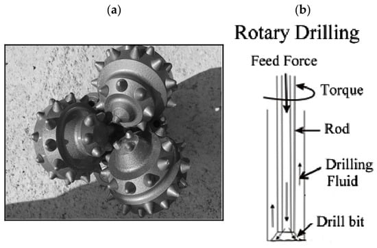
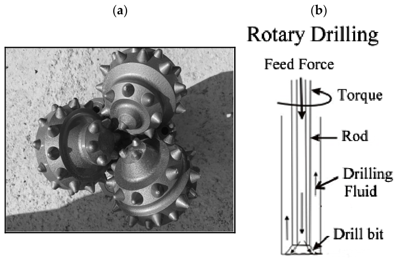
Mechanical drilling methods can generally be classified as rotary drilling and rotary percussive drilling. For blasthole drilling, the rotary percussive method was commonly used before the 1950s [1]. Tricone bits with compressed air circulation through their bearings, as shown in Figure 1a, were developed in 1949 and were introduced into blasthole drilling operations. The use of high-energy-efficiency explosives such as ANFO in surface mining operations resulted in more production carried out by rotary drill rigs with tricone bits, especially those with large diameters [1,2,3]. In rotary drilling methods, as shown in Figure 1b, feed force is applied at the top of the drill string, which is rotated by a hydraulic or electrical motor, while the bottom of the hole is flushed by drilling fluids such as air, water or drilling muds, which combine water, clay and many different additives [1,2,3,4].
Figure 1.
(a) An air-cooled tricone bit. (b) Main elements of rotary drilling.
Tricone bits are the most commonly used cutting tools, with a 98% use rate in rotary drilling; they are generally classified as having milled-tooth or tungsten-carbide insert bits, which have 3–9 times higher performance than the first type. Bit parameters such as cones, teeth and bearings can be designed differently considering the aim of drilling and the formation properties [3,4]. To make the selection of tricone bits simple for users, standardization was conducted by the International Association of Drilling Contractors, called the IADC code; it includes four digits, with three numeric and one alphanumeric [5]. The first two digits are related to formation hardness, and the third digit indicates the bearing type, which is used for special properties. Even though IADC is a unique method to select the bits used in a specific formation, there are many parameters that affect the drilling rate and their durability [6]. Acaroglu et al. have claimed that it should first be considered whether the bit is produced with the right materials and metallurgical processes when selecting the bit for drilling formation, since unqualified production is becoming widespread [6]. The importance of measuring drillability parameters and observing machine parameters has also been mentioned in the field to ensure the proper bit is selected for formations [6,7].
When a rotary drilling method is used in surface mining, blastholes are generally drilled with tricone bits with air-cooled bearings. In total, 25–30% of the pressurized air passes through the bearings, as shown in Figure 1a, to cool and increase the life of this type of tricone bit [3]. This figure also shows how compressed air is released from the three nozzles, which direct the air jet towards the bottom of the blasthole so that cuttings can be rapidly removed. Therefore, the use of an appropriate nozzle diameter results in a faster penetration rate and increases the life of the bit [1,3].
There are three parameters that indicate the performance of a drill, namely rate of drilling (ROP), energy consumption per unit volume of rock, and consumables, especially bits. Efficient drilling means the former are high and the latter are low. Although there are many parameters that affect these performance parameters, it is possible to group them into three main groups [8]. The first group includes the physical, mechanical and mass properties of rocks; the second group includes the drilling machine and bit parameters; and the last one includes working conditions [8]. These three main parameters are also classified as controllable or uncontrollable. For example, feed force, rotational speed, machine and bit type and working conditions can be controlled, and they can increase drilling performance when optimum values are obtained. Many studies have been carried out to estimate performance parameters to increase the efficiency of drilling machines, as summarized below. ROP estimation is particularly important for determining the efficiency, completion time and cost of drilling [6].
Some researchers have explained that there are many rock mechanical and rock mass parameters which affect the drillability of rocks [8,9,10,11,12,13]. Thuro and Spaun have determined that the parameter of specific destruction work is the most effecting factor on the ROP and the quartz content is directly related to abrasiveness of the drill bit [8]. They have also explained the effect of rock discontinuity on the ROP [8]. In other studies, uniaxial compressive strength (UCS) has been determined as the dominant rock property for the prediction of ROP of rotary blasthole drills [11,14]. Pandey et al. have also shown that with an increase in UCS and Protodyakonov index, drillability of rock decreases [15]. Kahraman has developed an equation for rotary drilling machines based on UCS of rock, bit diameter, weight on bit (WOB) and rotary per minute (RPM) of drillers [16]. Kahraman has also developed a model named the drillability index for spherical and conical button tungsten carbide bit teeth. This index is defined from force-penetration curves [17], and it is closely related to rock properties such as UCS, Brazilian tensile strength (BTS), Schmidt hammer strength (SHS), impact strength, P-wave velocity, elastic modulus and rock density [17]. More recently, measurement-while-drilling (MWD) parameters have been used to predict rock strength and identify rock drillability [18]. Howarth and Rowlands [19] correlated the texture coefficient with drillability and strength properties, while Karrari et al. [20] related petrographic and fabric features to geomechanical, abrasivity, and drillability properties.
Altindag found that the brittleness index (BI, half the product of UCS and BTS) is closely related to the rock drillability index, point load index (PLI), density, cone indenter value, SHS, and seismic velocity [21]. Yarali and Kahraman also investigated the relationship between BI and the drilling rate index (DRI) for 32 different rock types [22]. A strong exponential relationship was found between DRI and BI, and it was concluded that BI could be used to assess rock drillability [22].
Some researchers have pointed out that rock-mass structural parameters should be included in drillability models [13,23]. Hosseinie et al. described a new classification system for the drillability of rocks, termed the rock mass drillability index (RDi), based on six parameters: texture and grain size, Mohs hardness, UCS, joint spacing, joint filling (aperture), and joint dip [23]. Using this RDi, a new drilling-rate equation was developed using WOB, RPM, flushing air pressure, and bit diameter [24]. Cheniany et al. developed empirical equations for the ROP of rotary drills based on UCS, SHS, quartz content, FeS2 content, fragment size (d80), alteration, joint dip of the rock mass, and two operational parameters: RPM and feed force. They also developed the Specific Rock Mass Drillability (SRMD) index based on the same parameters [25].
RPM and feed force in rotary drilling can be controlled to increase ROP, which is a primary indicator of drilling performance [7,26,27,28]. For softer formations, feed force and RPM can generally be increased provided that the bit teeth do not get stuck in the rock. In harder formations, efficient drilling generally requires a lower RPM so that the teeth can achieve greater penetration per revolution [29]. For tricone bits used in blasthole drilling, rotational speed typically ranges from 60 to 120 [1]. Furthermore, Kumar et al. [30] reported that ROP increases with increasing RPM and feed force, and similar relationships were obtained by Fish [31] and Feng et al. [32]. However, Liu and Yin [33] reported a negative correlation between ROP and feed force. The feed force applied to a tricone bit can be approximately estimated from the bit diameter and the UCS of the rock, which generally varies along the drilling length [1]. Therefore, RPM and feed force should be optimized as formation conditions change to maintain efficient drilling performance [7,26,27]. Drilling performance can be assessed by monitoring ROP, drill-cutting characteristics, and relevant machine parameters [30,34,35].
Particle-size indices of drill cuttings obtained from sieve analysis can be useful indicators of drilling efficiency [34,35]. Pfleider and Blake and Ismailova et al. indicated that ROP increases with the size of drill cuttings [35,36]. Several researchers have investigated relationships between cuttings-size indices, ROP, and drill operating parameters [34,35]. Sieve analysis provides indices such as the mean particle size (d50) and coarseness index (CI), which is calculated from the sum of cumulative weight percentages [37]. Additional parameters, including d36.8 (particle size at 36.8% cumulative passing) and n (the Rosin–Rammler uniformity/exponent parameter), are derived from the particle-size distribution using a Rosin–Rammler plot [38,39]. Specific surface area (SSA), defined as the ratio of particle surface area to volume, is also used as an index [37]. Altindag obtained equations relating ROP to d50, CI, and SSA, indicating positive correlations with d50 and CI and an inverse relationship with SSA [37]. Kumar et al. reported similar relationships and proposed an equation [40]. Yang et al. investigated the relationships between drill-cutting particle-size distribution and drilling penetration and rotational rates [34]. The importance of measuring drillability parameters and monitoring machine parameters in the field when selecting an appropriate bit for a given formation has also been emphasized [11,18,41].
Recent studies indicate that research on tricone and roller-cone bits is directed toward condition monitoring and bit design optimization. A wear-monitoring and failure-prediction approach has been developed for tricone bits in surface mining, with emphasis on vibration signals and mining automation [42]. Toshov et al. focused on improving roller-cone bit geometry through axial eccentricity optimization, while Minieiev et al. examined an optimized multicone bit configuration for hard rocks [43,44].
1.2. Flushing in Tricone Bits
Efficient flushing is critically important in drilling because it accounts for approximately 50% of the total drilling energy. If residual cuttings remain at the bottom of the hole and are repeatedly recut by the bit, energy consumption and bit abrasion increase substantially [1].
The flushing fluid is selected according to the drilling method, machine and operating parameters, and formation properties. Compressed air is widely used in blasthole drilling because blastholes are generally temporary and do not need to remain open for long periods. It can increase drilling rate, and it helps to keep the borehole clear [2,4]. Flushing and drilling efficiency are affected by the number and diameter of the nozzles, which are selected based on machine type, formation properties, hole length and diameter, and compressor capacity [3].
The hydraulic performance of rotary drilling systems has been investigated for several decades, mainly in relation to jet impact, bottom-hole cleaning, pressure distribution, and drilling performance [45,46,47,48,49,50,51,52,53]. Early studies established that the effective removal of rock fragments from the borehole bottom is essential for maintaining penetration efficiency. Subsequent investigations showed that nozzle size, number and extension significantly influence pressure distribution and jet impact beneath the bit [49,50]. Warren and Winters demonstrated that a greater fraction of the available jet energy reached the borehole bottom when smaller-diameter jets were used, indicating that nozzle diameter strongly affects the effective transfer of hydraulic energy beneath a tricone bit [50]. Alternative nozzle arrangements, including directed jets, extended slant nozzles, and asymmetric nozzle sizing, were later investigated to improve jet effectiveness and cuttings removal [49,50,51,52,53]. With the development of numerical techniques, laboratory experiments and three-dimensional flow simulations were increasingly combined to optimize roller-cone bit hydraulics and evaluate cone cleaning, bottom-hole cleaning, and cuttings evacuation under different nozzle configurations [52,53].
More recent studies have increasingly focused on numerical simulation and optimization of nozzle geometry and flow behavior. He et al. (2021) showed that nozzle diameter, jet angle, and stand-off distance significantly influence rock-breaking efficiency [54]. Wu et al. (2022) used CFD to investigate the effects of jet configuration on bottom-hole cleaning [55]. For tricone bits, Bahrainian et al. (2018) numerically evaluated different nozzle diameters and and investigated their influence on tri-cone bit pressure drop [56]. Their numerical results indicated that pressure loss is highly sensitive to nozzle diameter, with smaller nozzle openings producing greater hydraulic resistance for a given circulating flow condition. Wayo et al. (2023) used computational fluid dynamics (CFD) to evaluate a modified multi-nozzle roller-cone configuration designed to improve fluid circulation and cuttings transport [57]. Shi and Li (2024) showed that nozzle arrangement can significantly alter velocity and pressure distributions near the borehole bottom [58]. Recent studies on other drilling systems have also shown that nozzle configuration and hydraulic parameters strongly affect bit cleaning, cuttings transport, and drilling performance [46,59]. Most recently, Nazarbekova and Nurtoev (2026) simultaneously considered nozzle diameter, inclination angle, and stand-off distance to improve bottom-hole cleaning performance in roller-cone drilling [60].
Overall, previous studies clearly demonstrate that nozzle diameter, number, orientation, extension, and flow distribution are key parameters affecting pressure loss, jet impact, cuttings removal, and drilling performance. However, much of the literature has focused on petroleum drilling systems using liquid-based circulating fluids, whereas comparatively fewer studies have addressed compressed air circulation and nozzle selection in mining tricone drilling. Lei et al. (2023) and particularly Yan et al. (2024) have recently investigated mining tricone bit nozzle systems; however, comparatively limited attention has been given to nozzle-size selection [61,62]. Lei et al. (2023) investigated severe cone tooth and surface erosion and abrasive wear occurring in tricone bits [61]. To reduce this wear, two different circular nozzle diameters were evaluated using CFD analysis, and the larger nozzle diameter was found to be more suitable because it reduced the shear stress acting on the cone surface while maintaining enough airflow for cuttings removal [61]. Conventional circular nozzles are commonly used in air-cooled mining tricone bits; however, Yan et al. (2024) investigated the effects of four geometric parameters of a tricone air nozzle using CFD and orthogonal experimental design [62]. The inner diameter of the parallel section of the nozzle was found to be the most influential parameter, with a smaller diameter producing a higher air velocity at the nozzle outlet [62].
Therefore, this study addresses this practical gap by combining theoretical calculations with field measurements to determine an appropriate nozzle diameter for air-cooled tricone bits used in mining operations. The effects of different nozzle diameters on drilling performance were evaluated under actual operating conditions, and the selected nozzle diameter was subsequently examined using tricone bits with different IADC codes.
1.3. Estimation of Air Volume for Flushing
In a drilling operation, the compressor must supply the airflow rate and pressure required for efficient flushing. The required airflow rate (m3/min) is calculated using Equation (1) after estimating the air bailing velocity (m/min) [1,3].
Q = (Vb × π × (D2 − d2))/4 × 106
Q = Air volume supplied by Compressor (m3/min);
Vb = Air bailing velocity (m/min);
D = Hole (bit) diameter (mm);
d = Drill string diameter (mm).
In a blasthole, cuttings are first removed from the bottom of the hole by compressed air and then transported upward through the annulus. They are ultimately discharged from the hole at an air velocity referred to as the bailing velocity. To estimate this velocity, the forces acting on a rock particle in the hole—gravitational, buoyant, and drag forces—are considered, as shown in Figure 2, and the individual forces and the net force are expressed in Equations (2)–(5) [3].
Figure 2.
Forces acting on a spherical rock particle during flushing.
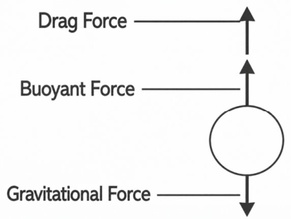
Net Force on the particle = Gravitational force − (Drag force + Buoyant force)
Fg = 4 × π × r3 × dm × g/3
Fb = 4 × π × r3 × df × g/3
Fd = (Cdf + Cdd) × A × df × V2/2 or Fd = Cd × A × df × V2/2
Fg = Gravitational force;
Fb = Buoyant force;
Fd = Drag force;
r = Radius of the falling spherical particle;
dm = Density of the particle;
g = Gravitational constant (9.80665 m/s2);
df = Density of the fluid;
Cdf = Coefficient of drag due to the friction between the particle and medium;
Cdd = Coefficient of drag due to the need for displacing the medium;
Cd = Coefficient of drag;
V = Velocity of the falling spherical particle;
A = Area of cross section of the particle in the direction perpendicular to the direction of its movement.
The gravitational and buoyant forces remain nearly constant as the particle falls through the fluid. The drag force increases and, together with the buoyant force, eventually balances the gravitational force. At this point, the particle falls at a constant velocity, referred to as the terminal (settling) velocity, Vt. In this region Cd is taken as 0.44 based on the Reynolds number, yielding Equation (6) [3].
Vt = (6.06 × r × g × ((dm − df)/df))0.5
Bailing velocity (Vb), as used in Equation (1), is the upward velocity of compressed air through the annular space between the drill string and the borehole wall. It is taken as 10% higher than the terminal velocity, as shown in Equation (7), to ensure the upward transport of the particles.
Because these equations are derived theoretically under simplifying assumptions, correction factors are required for application to actual drilling operations. Therefore, the terminal velocity is multiplied by a correction factor, α, which accounts for several formation and operational parameters, as shown in Equation (7). The individual factors included in α are given in Equation (8) [3].
where
Vb = 1.1 × α × Vt
α = A factor depending upon many conditions;
Vt = A value for terminal velocity calculated on certain assumptions.
α = αr × αd × αrou × αrnd × αfr × αa × αi × αw
α depends on fragment size (αr), fragment density (αd), fragment roundness (αrou), fragment roughness (αrnd), fragmentation rate (αfr), annular space (αa), inclination of the blasthole (αi) and water-injection amount (αw, if any) [3].
Equation (8) gives the final expression used to determine the desirable bailing velocity of flushing air for blastholes, which are typically less than 30 m deep. In drilling operations, bailing velocity generally ranges from 900 to 2400 m/min. Optimizing the bailing velocity and selecting compressor capacity accordingly are essential for minimizing the energy consumed by flushing and reducing bit wear. These equations can also be used to verify whether the compressor currently used in a drilling operation is suitable [3].
1.4. Estimation of Air Pressure for Flushing
After the required airflow rate has been calculated, the compressor pressure necessary to ensure adequate airflow through the system must be estimated. The components through which compressed airflows differ among blasthole drills, and their number and configuration vary from one machine to another. Therefore, pressure losses through these components should be evaluated for each blasthole drill. Although the theoretical treatment of these losses is approximate, calculations typically consider the diameters and lengths of metal pipes and hoses, blasthole diameter, and the inner and outer diameters of the drill pipe. The nozzles must provide sufficient pressure loss to ensure that approximately 30% of the compressed air flows through the bearings, while the remaining 70% passes through the nozzles at the bottom of the hole. The required pressure loss while this airflow passes through the flushing system can be estimated using the following equation. Under most conditions, (pd + pa) is less than 100 kPa [3].
where
pr = pc − (pd + pa)
pr = Pressure loss to be achieved through use of nozzles;
pc = Pressure of compressed air at air compressor;
pd = Pressure lost while compressed air flows to the tricone drill bit;
pa = Pressure required at the blasthole bottom to ensure that cutting laden air passes through the annulus.
1.5. Determining Size of Nozzle Diameter
In a tricone bit, nozzle size should be selected carefully to achieve a high penetration rate while maintaining a long bit life. This can be achieved by sizing the nozzles so that approximately 20–30% of the compressed air passes through the bearings of the tricone bit. Equation (10) can be used to determine the nozzle size for a specified volumetric flow rate [3].
Q = Volume flow rate in m3/min;
α = Nozzle efficiency;
ψ = Flow coefficient;
P1 = Upstream absolute pressure in Pa;
T1 = Upstream absolute temperature in K;
A = Area of nozzle opening in m2;
R = Gas constant in J/(kg K).
In most cases, selecting a smaller nozzle diameter is preferable because a smaller nozzle produces a higher pressure drop, discharges less air through the nozzles, and therefore directs more compressed air through the bearings of the tricone bit. Catalogs and published tables [3] also provide nozzle sizes available for tricone bits. However, the theoretical equations, tables, and catalogs are based on assumptions and provide only approximate estimates because of the uncertainties involved. Therefore, this study proposes a practical method for selecting actual nozzle sizes for tricone bits under field drilling conditions while also considering theoretical approaches.
2. Study Area
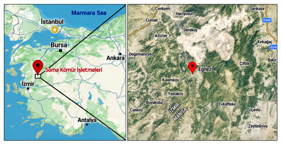
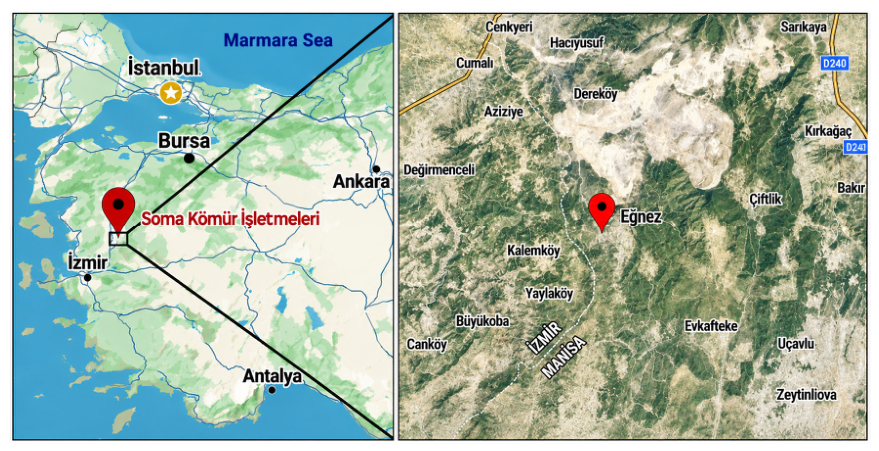
This study was conducted in the Soma Coal Basin of Turkish Coal Enterprises (TKI). The Soma Basin, located in western Türkiye (Figure 3), is one of the country’s major coal deposits and contains approximately 738 Mt of lignite. Annual production is approximately 10.4 Mt, most of which is extracted from the open-pit Aegean Lignite Enterprise (ELI) operated by Turkish Coal Enterprises. Approximately 7.7 Mt is supplied to the 990 MW Soma Power Plant, while the remaining coal is used for domestic and industrial purposes [63,64].
Figure 3.
Location map of the study area in the Soma Coal Basin.
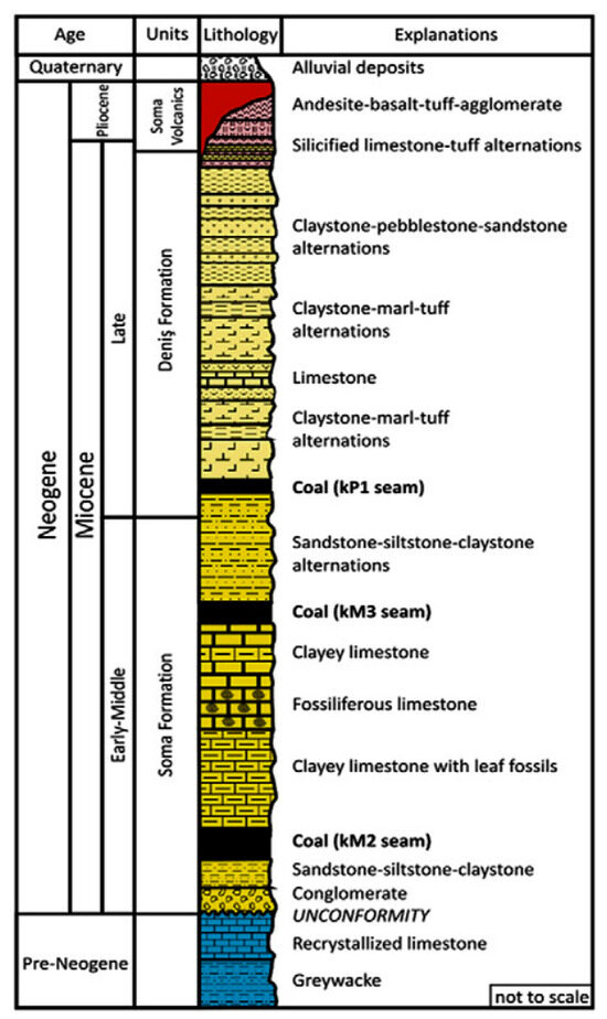
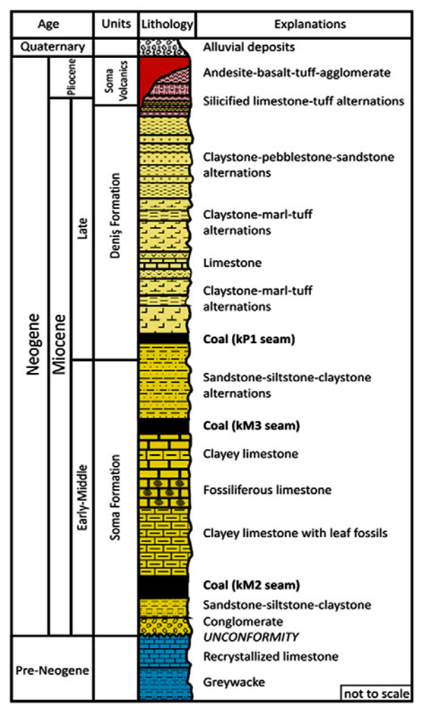
The NE–SW-trending Soma Basin is approximately 20 km long and 5 km wide and is a fault-controlled basin. Alpine orogeny created basins for Miocene deposition within the Paleozoic and Mesozoic basement rocks through folding and, particularly, graben-type faulting. Deposition of the major coal-bearing Soma Formation began during the Early to Middle Miocene. The formation consists of alluvial sediments and lacustrine carbonates that host the KM2 and KM3 lignite seams (Figure 4). From bottom to top, the Neogene succession comprises the Miocene Basement Series (pebblestone, sandstone, and clay; M1), Lower Lignite Series (KM2), Marl Series (M2), Limestone Series (M3), Middle Lignite Series (KM3), Pliocene Sandstone–Siltstone–Mottled Clay Series (P1), Upper Lignite Series (KP1), Clay–Tuff–Marl Series (P2ab), Clay–Sandstone–Pebblestone Series (P2c), and Silicified Limestone–Tuff Series (P3) [64,65].
Figure 4.
Generalized stratigraphic illustration of the Soma Coal Basin [64], reproduced with permission from Karayigit et al., International Journal of Coal Geology, published by Elsevier, 2017.
Because of the geological setting, the coal seams in the study area occur independently of one another. The Eynez (also called Eğnez) sector of the Soma Formation (Figure 3), where this study was conducted, contains all three coal seams: the upper seam (KP1), middle seam (KM3), and lower seam (KM2), as shown in Figure 4.
3. Material and Methods
3.1. Drilling Machines in Soma Coal Basin
In the Eynez region of the Soma Basin, coal and overburden are excavated using shovels, dump trucks, and draglines. Before excavation, the formation is loosened by drilling and blasting. Blastholes are drilled to a diameter of 22.86 cm (9 in) and are typically approximately 15 m long, depending on bench thickness. Approximately 20 holes loaded with a mixture of ANFO and waterproof emulsion (Nitromak DNX Chemical Industry Inc., Soma, Manisa, Türkiye) [66] are blasted in each round [67,68].
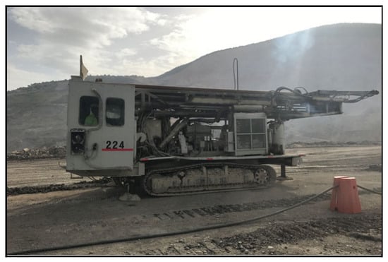
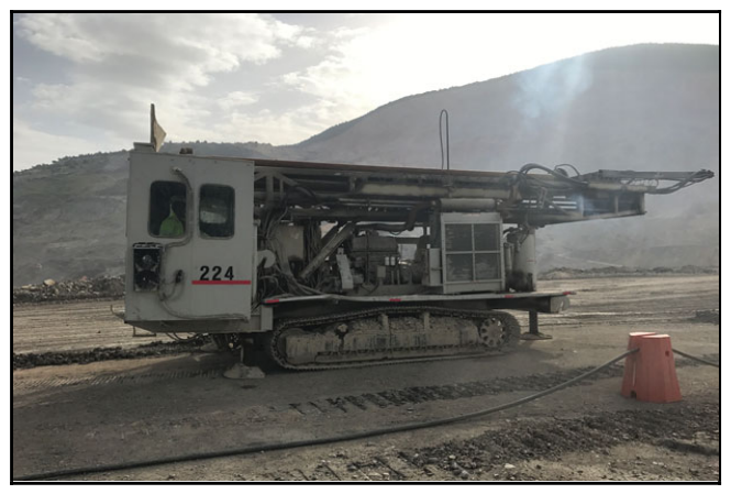
Five drilling machines were active during the study. Machines 223 (Reedrill SK50T; Reedrill, Inc., Sherman, TX, USA) and 224 (Ingersoll Rand DM50; Ingersoll Rand Company, Drilling Solutions, Garland, TX, USA), shown in Figure 5, were selected for this study because they exhibited the highest performance and experienced fewer breakdowns. Both machines have a maximum feed force of 22,680 kg, a compressor capacity of 25.5 m3/min, a maximum drilling diameter of 23 cm, and a drill rod length of 7.6 m. Machine 224 operates at a maximum rotation speed of 130 RPM with a maximum torque of 9706 Nm and an engine power of 298.4 kW, whereas machine 223 provides a slightly higher maximum rotation speed of 135 RPM and a higher engine power of 320 kW, but a lower maximum torque of 8330 Nm [67,68,69].
Figure 5.
A drilling machine in Eynez.
3.2. Physical and Mechanical Rock Properties of Study Area
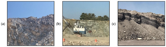
The overburden of the Soma coal formation is generally heterogeneous and consists of different rock types and geological discontinuities. During the study, three draglines, designated Marion 1, Marion 2, and Marion 8, were excavating overburden with different lithological characteristics. The corresponding areas were selected as study sites and referred to as the dragline sites, following the terminology already used at Eynez. As shown in Figure 6, the Marion 1 area generally consists of cream, beige, grayish, and reddish marl and limestone; the Marion 2 area consists of pebblestone, sandstone, and clay; and the Marion 8 area consists of claystone and lignite. Four block samples were collected to determine the physical and mechanical properties of the rocks in these three areas [67,68].
Figure 6.
Study Fields in Soma Coal Basin (a) Marion 1, (b) Marion 2 and (c) Marion 8.
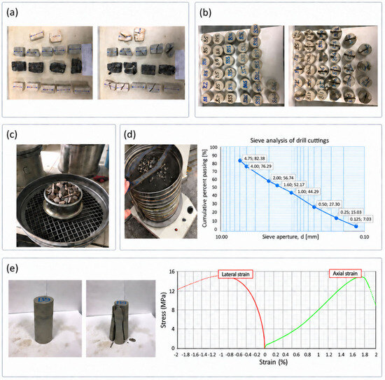
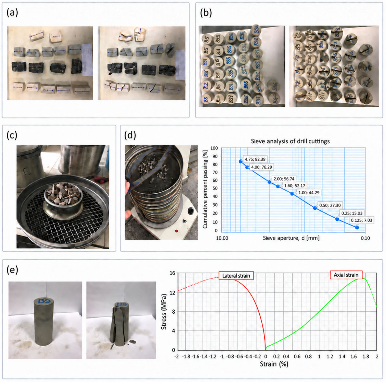
Using these samples, density and moisture content were determined as physical properties, while uniaxial compressive strength, elastic modulus, Poisson’s ratio, indirect tensile strength, Schmidt rebound value, impact strength, and point load strength were measured as mechanical properties according to the relevant standards [70]. Figure 7 presents representative samples and laboratory test setups, and Table 1 summarizes the physical and mechanical properties together with their statistical parameters [67,68]. Point load index values, used as indicators of formation hardness, and sieve-analysis parameters (CI, n, d50, and d36.8), used as indicators of drilling performance, are presented later together with the drilling-machine performance measurements.
Figure 7.
Samples from laboratory tests and their specimens: (a) point load strength specimens; (b) Brazilian tensile strength specimens; (c) impact strength test; (d) sieve analysis of drill cuttings; and (e) uniaxial compressive strength specimens before and after failure and the corresponding test curve.
Table 1.
Physical and mechanical properties of rocks in the study areas of Soma Coal Basin.
3.3. The Method
3.3.1. Evaluation of Current Drilling Operations
Drilling-performance parameters, such as penetration rate, energy consumption, and bit consumption, are affected by both controllable and uncontrollable parameters, as discussed above [8,9,10]. This study proposes a new approach for selecting the optimum nozzle diameter for tricone bits in an open-pit mine by observing and evaluating drilling-performance parameters. However, other controllable drilling parameters, particularly the applied RPM, feed force, and bit IADC code, should first be evaluated at the study site.
In rotary drilling, RPM is generally increased as the rock becomes softer [1]. Drills with relatively high fixed rotational speeds, such as 110 RPM, are used at Soma because the formations are not particularly difficult to drill and this operating mode is convenient for the operators. Feed force could not be kept constant because of the heterogeneous formations and was generally adjusted according to formation hardness. The blastholes are 22.86 cm (9 in) in diameter and approximately 15 m long. IADC 622 tricone bits have been used most frequently, although bits with IADC codes 522, 532, and 722 have also been used for many years. Qualified bits have an average service life of approximately 10,000 m. These IADC codes are considered suitable for formations of medium hardness. At the beginning of this study, a qualified IADC 622 tricone bit with limited prior use and equipped with 16 mm circular steel nozzles was operating at the study site. The ROP of this bit was measured as 1.10, 1.22, and 1.37 m/min in the Marion 1, Marion 2, and Marion 8 formations, respectively.
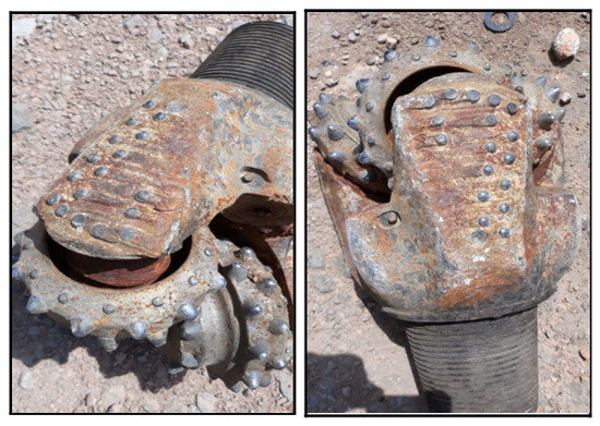
All failed unqualified tricone bits used in the study area were examined, and no significant visible wear was observed on the cone teeth or other major components (Figure 8) [67,68]. Only slight wear was identified on the shirttails and shirttail inserts. However, detached cones were observed as a result of bearing-system failure, and this was identified as the principal failure mode. This damage corresponds to the lost cone (LC) dull characteristic defined in the IADC Drilling Manual [71], which refers to the loss or detachment of a cone from the bit. For the bits examined in this study, the observed LC damage was attributed to failure of the bearing system.
Figure 8.
Common failure types of tricone bits used in the Soma Basin.
This failure may have resulted from very limited or absent airflow through the bearings, combined with the use of unqualified tricone bits. Insufficient air circulation through the bearings may have caused the bearings and surrounding surfaces to overheat, potentially reducing the hardness of the carburized case. This type of failure can be mitigated by selecting an appropriate nozzle diameter for a qualified tricone bit. Nozzle size should be selected by considering operating conditions, formation properties, and machine characteristics. As in many other mining operations, no study had previously been conducted at the Soma mine to determine the optimum nozzle diameter for tricone bits. The bits were generally operated with nozzles either supplied by dealers or selected from manufacturers’ catalogs [67,68].
3.3.2. Definition of Optimum Nozzle Size
In blasthole drilling operations, the required airflow rate and operating pressure should first be determined based on the drilling conditions if the compressor has not yet been specified. However, when a compressor is already installed, or its capacity is fixed, nozzle selection should be carried out within the available airflow and pressure limits of the existing compressor.
In Soma, all drilling machines are equipped with compressors of fixed capacity and similar characteristics. The airflow capacity is approximately 25 m3/min at 350–500 kPa. At the time of the study, IADC 622 tricone bits with a diameter of 22.86 cm (9 in), equipped with 16 mm diameter nozzles, and drill rods with a diameter of 17.78 cm (7 in) were in use. When the entire airflow is used for flushing, the calculated air bailing velocity is approximately 1600 m/min according to Equation (1).
For this fixed airflow rate, the optimum nozzle diameter that allows 75% of the total air to pass through the nozzles was estimated using Equation (10). The following parameters were used: Q = 25 m3/min, α = 0.95, ψ = 0.4841, P1 = 400,000 Pa, T1 = 303.16 °K (for 30 °C), R = 287.1 J/(kg K). From this calculation, A = 123 × 10−6 m2 was obtained for the total nozzle area. This corresponds to a nozzle diameter of 12.5 mm, allowing approximately 25% of the total airflow to pass through the bearings of the tricone bit.
Table 2 [3], which is also based on Equation (10), can be used for nozzle selection. For the compressor parameters considered in this study—an airflow rate of Q = 24–26 m3/min and a compressor pressure of 379–448 kPa—a nozzle diameter in the range 12.19–13.79 mm is considered appropriate.
Table 2.
Nozzle diameter values corresponding to the airflow and pressure conditions considered in this study, based on Gokhale [3].
These calculations indicate that a 16 mm nozzle might not provide sufficient airflow to the bearings. However, the calculated nozzle size was theoretical and therefore needed to be verified under actual formation and operating conditions because field values may differ from theoretical estimates. Accordingly, a practical method was developed in this study. The method includes the following steps:
First, the nozzle size is calculated theoretically and then evaluated in the field. If the calculated size performs satisfactorily, smaller nozzle sizes can be tested provided that they do not impose excessive load on the compressor or drilling machine. If the theoretical nozzle size does not perform satisfactorily, larger nozzles can be tested. During this process, the compressor should be monitored, drilling-machine performance parameters should be recorded, and the tricone bit and nozzles should be inspected for wear. The optimum nozzle size can then be identified as the size that does not cause problems in the compressor, drilling machine, or bit while maintaining satisfactory drilling performance, as described in the following sections.
Based on the calculated range, a 13 mm nozzle was initially selected to apply this method. The 14.5 mm nozzle diameter was selected as an intermediate value within the 13–16 mm range. Because the 16 mm nozzle was already in use, it was included in the measurements for comparison. To evaluate the effect of nozzle size on drilling-machine efficiency, the other operating parameters were kept as constant as practically possible when the nozzle diameter was changed.
First, the effects of nozzles with inner diameters of 13, 14.5, and 16 mm on the drilling performance of a qualified IADC 622 tricone bit were investigated. All nozzles had a constant circular cross-section along their entire length. The machine performance parameters (ROP, feed force, main pump pressure, and flushing air pressure), point load strength as an indicator of formation strength, and drill-cutting parameters used to assess drilling performance (CI, d50, d36.8, and n) were determined. Based on the results, the optimum nozzle diameter was defined as the size that did not cause excessive loading of the compressor or adversely affect drilling performance.
Subsequently, a total of three different qualified tricone bits with IADC codes 532 and 722 (Thompson International Inc., Henderson, KY, USA) and 622 (Volgaburmash JSC, Samara, Russia) were used in the study [72,73]. After the optimum nozzle diameter had been determined using the IADC 622 tricone bit, the same nozzle diameter was also applied to two new tricone bits with IADC codes 532 and 722. Their drilling-performance parameters were then measured and compared with those obtained from the IADC 622 bit equipped with the same nozzle diameter to evaluate the effect of bit type on drilling performance under identical nozzle conditions. The bit-life determination study for the IADC 622 tricone bit using the 14.5 mm nozzle could not be conducted because suitable drilling machines were unavailable during the study period. The experimental procedures and corresponding results are presented in detail in the following sections.
3.3.3. Machine Performance Parameters
Because three formations, designated Marion 1, Marion 2, and Marion 8, were identified in the study area, drilling-performance parameters were evaluated separately for each formation after a new nozzle had been installed on the drill rig. For each formation, machine parameters, including feed pressure, main pump pressure, flushing air pressure, and drilling time, were measured in five holes selected from a blast round consisting of approximately 20 holes. Drill cuttings weighing approximately 3–4 kg were collected from two of these five holes for sieve analysis. The same procedure was repeated for a second blast round. After completion of the two blast rounds, point load test samples were collected from the loosened formation. Thus, for each formation, machine measurements were obtained from a total of 10 holes, four drill-cutting samples were collected for sieve analysis, and samples were obtained for point load testing. The same procedure was applied to the other two formations. In total, 155 point load samples were collected to determine formation strength, and 54 drill-cutting samples were obtained for sieve analysis from the three formations [67,68]. CI and d50 were determined from sieve analysis of the drill cuttings, while n and d36.8 were obtained by applying the Rosin–Rammler method [38,39] to the particle-size distributions. Summary statistics for these machine parameters, indices, and point load test results are presented in Table 3.
Table 3.
Values of performance parameters of machines with point load and cutting indices.
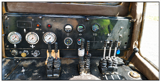
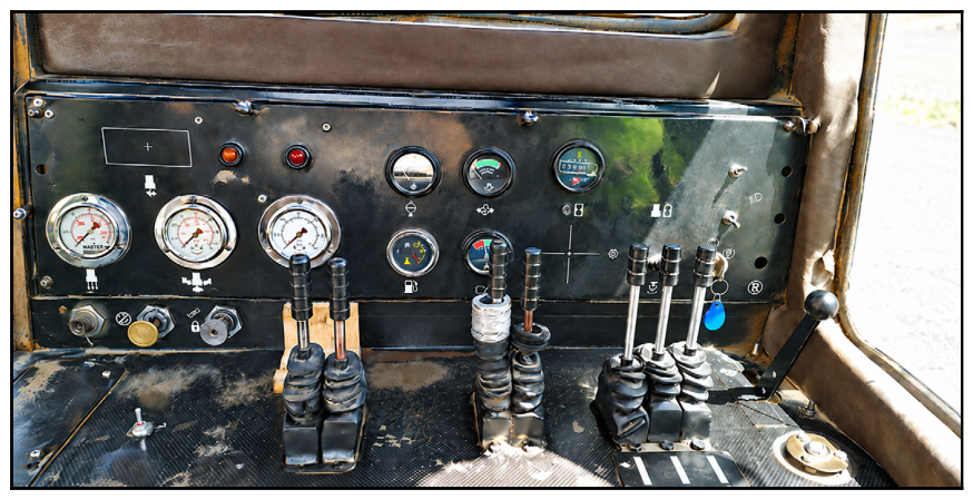
The above-mentioned machine parameters (feed pressure, main pump pressure, and flushing air pressure) were measured as follows. During the drilling of a 15 m hole, the readings of these parameters were frequently taken from the control panel (Figure 9) of the rig and recorded. The recorded values were then averaged, providing a single representative value for each machine parameter for a hole.
Figure 9.
Drilling rig (224) control panel used for monitoring the performance parameters.
4. Evaluation of Drilling Measurements in the Soma Basin for Determining the Optimum Nozzle Size
During tests with the 13 mm nozzle, compressor pressure increased, and the drilling machine experienced operating difficulties; breakdowns occurred in both the compressor and the drilling machine, particularly in the softer formations. Although measurements could be obtained with the 13 mm nozzle, this nozzle size was not considered suitable for the formation and operating conditions.
Table 4 presents the average drilling-performance parameters obtained using the same IADC 622 tricone bit with nozzle diameters of 13, 14.5, and 16 mm. A constant feed force could not be maintained because of the heterogeneous formations, as explained above. Therefore, Table 4 reports the applied feed force together with the main pump pressure, flushing air pressure, and point load index, the latter serving as an indicator of formation hardness.
Table 4.
Results of drilling performance measurements in Soma Coal Basin for different nozzle diameters.
According to Table 4, drilling rate and fuel consumption showed no major variation as nozzle diameter decreased. The particle-size distribution parameters obtained from sieve analysis were slightly higher for the 13 mm nozzle, indicating somewhat more efficient drilling as nozzle diameter decreased. This may be attributed to more effective cleaning of the hole bottom because air velocity increases as nozzle diameter decreases.
Table 4 indicates that the 14.5 mm nozzle can be selected to improve tricone-bit life without reducing drilling performance. The drilling rates obtained with the 14.5 mm nozzle in the Marion 1 and Marion 2 areas were similar. In Marion 8, the 14.5 mm nozzle produced the lowest drilling rate and the highest fuel consumption. However, the highest CI, d50, d36.8, and n values were also obtained with the 14.5 mm nozzle in Marion 8.
After the 14.5 mm nozzle diameter had been selected, it was also installed on two new tricone bits with IADC codes 532 and 722. Their measured drilling-performance parameters are presented in Table 5 together with those of the IADC 622 bit. Measurements for the IADC 532 and 722 bits could not be obtained in Marion 8 because work in that area had been completed. As shown in Table 5, drilling rates and fuel consumption were generally similar among the bits, except for the fuel consumption of the IADC 532 bit in the Marion 1 area. Table 5 also shows no major differences among the IADC 622, 532, and 722 bits equipped with 14.5 mm nozzles in terms of drilling rate, fuel consumption, and drill-cutting size. These results indicate that bit life may be increased by using the smallest suitable nozzle size that does not cause operational problems in the drilling machine or compressor.
Table 5.
Results of drilling performance measurements in Soma Coal Basin for different tricone bits with 14.5 mm nozzles.
The IADC 532 tricone bit was lost after drill-rod breakage in the hole at approximately 15,000 m of drilling, whereas the IADC 722 bit remained operational after 22,000 m. In the Soma Basin, qualified tricone bits typically have an average service life of approximately 10,000 m [6]. The results of this study suggest that tricone-bit life may be extended by using an optimum nozzle size selected with the proposed method. However, additional tricone bits should be tested with the optimum nozzle size and their service records analyzed. Performance parameters should also be measured at regular intervals, as in the present study, and the bit and nozzles should be inspected for signs of wear.
Since relatively few studies have examined nozzle selection for tricone bits in mining applications, there are limited published results available for direct comparison with the findings of this study. One of the most closely related studies was conducted by Lei et al. [61], who investigated nozzle-diameter optimization for a mining tricone bit with a diameter of 23.19 cm, a drill pipe with a diameter of 17.78 cm, and a hole depth of 20 m. In their application, considerable wear was observed on the cone teeth and surfaces, and nozzle diameters of 17 and 22 mm were compared using CFD analysis. The results showed that increasing the nozzle diameter reduced the surface shear stress acting on the cones and, consequently, the larger nozzle diameter was considered more suitable for reducing cone-surface erosion and wear. In their CFD model, the rated airflow capacity of the compressor was 53.8 m3/min. In contrast, the compressor used in the present study had a considerably lower capacity of 25.5 m3/min. Therefore, the difference in available compressor capacity should also be considered when comparing the nozzle diameters selected in the two studies.
In this study, the dominant failure mechanism was related to the bearing system rather than wear of the cone teeth or surfaces. Based on the assumption that insufficient airflow to the bearings could have contributed to this failure, nozzle selection was first evaluated theoretically and subsequently investigated through field measurements. Under these compressor and operating conditions, smaller nozzle diameters were found to be more appropriate. Although the two studies differ in terms of compressor capacity, observed wear mechanism, methodology, and selected nozzle diameter, both demonstrate that nozzle selection can have an important influence on tricone-bit wear and performance parameters. Furthermore, although satisfactory results were obtained under field conditions in this study, future investigations combining CFD analysis with field-scale validation would provide a more comprehensive assessment of the nozzles and bearings.
Overall, these studies demonstrate the importance of nozzle diameter in relation to bit wear and indicate that further investigations are required to better understand the relationships among nozzle diameter, compressor capacity, airflow distribution, and different wear and failure mechanisms in mining tricone bits.
5. Conclusions
Rotary drilling machines equipped with air-cooled tricone bits are widely used to achieve high production rates in open-pit mines. The drilling efficiency of these systems depends on numerous rock, machine, and operational parameters. Tricone bits are among the most consumable components of drilling machines, particularly in hard and abrasive formations, because they remain in continuous contact with the rock.
Flushing is a critical part of the drilling process and can account for approximately 50% of the total drilling energy. Optimum nozzle diameters improve bottom-hole cleaning and drilling efficiency by supporting higher penetration rates and longer bit life. Consequently, further field investigations are required to establish optimum nozzle sizes for mining applications under different geological and operating conditions.
In this study, a practical method was developed to determine the optimum nozzle diameter for air-cooled tricone bits by combining theoretical calculations with field measurements of drilling parameters. Used tricone bits from the Eynez region of the TKI Soma Coal Basin were examined, and the dominant failure mode was identified as bearing-related failure, including broken or failed bearings. Insufficient airflow through the bearings was considered a possible contributor to these failures; therefore, reducing nozzle diameter was investigated as a means of directing more air through the bearings and extending bit life. Before the study, nozzles with a diameter of 16 mm were used at the mine.
First, the appropriate nozzle diameter for the drilling conditions was theoretically estimated to be 12.5 mm. To verify this estimate in the field, a 13 mm nozzle was installed on the bit, and the compressor and drilling machine were monitored while drilling-performance parameters were recorded. Compressor pressure increased, the drilling machine experienced operating difficulties, and breakdowns occurred, particularly in softer formations. Therefore, the 13 mm nozzle was not considered suitable for these formation and operating conditions. A 14.5 mm nozzle was then installed on the same bit, and the drilling-performance parameters were measured; the same procedure was subsequently applied using a 16 mm nozzle.
The drilling machine and compressor operated properly with the 14.5 and 16 mm nozzles without breakdowns. Drilling-performance parameters did not differ substantially between these nozzle sizes, whereas the particle-size distribution parameters generally improved as nozzle diameter decreased. The 14.5 mm nozzle was therefore selected for these drilling conditions to improve bearing cooling and potentially extend bit life.
Qualified tricone bits in the Soma Basin typically have an average service life of approximately 10,000 m. The 14.5 mm nozzle was also installed on two new tricone bits with IADC codes 532 and 722. Considering drilling-performance parameters such as drilling rate, fuel consumption, and drill-cutting size, no major differences were observed between the IADC 532 and 722 bits equipped with the 14.5 mm nozzle. The IADC 532 bit was lost because of drill-rod breakage at approximately 15,000 m, whereas the IADC 722 bit remained operational after 22,000 m. However, additional studies are required to quantify the effect of nozzle size on tricone-bit life because bit-life measurements require long-term monitoring. During such studies, the compressor should be monitored, drilling-machine performance parameters should be recorded, and the bit and nozzles should be inspected for wear.
The results of this study and previous findings [61] indicate that nozzle diameter can significantly influence tricone-bit wear and performance and that appropriate nozzle selection depends on operating conditions, particularly compressor capacity, airflow distribution, and the dominant wear or failure mechanism. Further field validation supported by CFD studies is recommended to improve nozzle selection for mining tricone bits. Future research could combine CFD simulations with experimental measurements of air velocity and nozzle-outlet pressure, as well as thermal measurements of the bit under different nozzle-diameter conditions, while also considering other drilling conditions such as hole deviation.
Overall, the nozzle diameter of air-cooled tricone bits can be estimated theoretically, selected from catalogs or tables, or simply retained as supplied. This study demonstrates that the optimum nozzle size can be selected more reliably using a practical method that combines theoretical calculations with field observations and measurements of drilling-performance parameters.
Author Contributions
Ö.A.: Conceptualization, Methodology, Supervision, Project administration, Funding acquisition, Resources, and Writing—original draft. H.M.Y.: Investigation, including sample collection and laboratory experiments, Formal analysis, Visualization, and Writing—review and editing. Both authors contributed to Data curation and Validation. All authors have read and agreed to the published version of the manuscript.
Funding
This research was funded by the Scientific and Technological Research Council of Türkiye (TÜBİTAK), grant number 216M117.
Data Availability Statement
All relevant data supporting the findings of this study are available within the article.
Acknowledgments
This study includes part of the thesis of H. Yüksel. The authors would like to express their gratitude to the employees of Soma TKI for their assistance.
Conflicts of Interest
The authors have no financial or proprietary interests in any material discussed in this article.
References
- Jimeno, C.L.; Jimeno, E.L.; Carcedo, F.J.A. Drilling and Blasting of Rocks; A.A. Balkema: Rotterdam, The Netherlands, 1995. [Google Scholar]
- Ersoy, A. Drilling Techniques and Applications; Nobel Kitapevi: Adana, Turkey, 2008. (In Turkish) [Google Scholar]
- Gokhale, B.V. Rotary Drilling and Blasting in Large Surface Mines; Taylor & Francis Group: Abingdon, UK, 2011. [Google Scholar]
- Yalcin, A.; Yalcin, B. Drilling Methods and Applications; TMMOB: Istanbul, Turkey, 2011. (In Turkish) [Google Scholar]
- McGehee, D.Y.; Dahlem, J.S.; Gieck, J.C.; Kost, B.; Lafuze, D.; Reinsvold, C.H.; Steinke, S.C. The IADC Roller Bit Dull Grading System. In Proceedings of the IADC/SPE Drilling Conference, New Orleans, LA, USA, 18–21 February 1992; SPE: Dallas, TX, USA, 1992; p. SPE-23938-MS. [Google Scholar] [CrossRef]
- Acaroglu, O.; Unlu, S.; Hasipek, B. Crucial Parameters to be considered for selection of rotary tricone bits. Sci. Min. J. 2020, 59, 275–285. (In Turkish) [Google Scholar] [CrossRef] [Scilit]
- He, X.; He, Y.; Wen, G.; Wang, Y. Simulation-driven rate-of-penetration prediction and multi-objective optimization of drilling parameters for tricone bits. Res. Sq. 2026. [Google Scholar] [CrossRef] [Scilit] [PubMed]
- Thuro, K.; Spaun, G. Drillability in hard rock drill and blast Tunnelling. Felsbau 1996, 14, 103–109. [Google Scholar]
- Thuro, K.; Spaun, G. Introducing the destruction work as a new rock property of toughness referring to drillability in conventional drill blast tunnelling. In Proceedings of the ISRM International Symposium—EUROCK 96, Turin, Italy, 2–5 September 1996; SPE: Dallas, TX, USA, 1996; p. ISRM-EUROCK-1996-088. [Google Scholar]
- Thuro, K. Drillability prediction: Geological influences in hard rock drill and blast tunnelling. Geol. Rundsch. 1997, 86, 426–438. [Google Scholar] [CrossRef] [Scilit]
- Kolapo, P. Investigating the effects of mechanical properties of rocks on specific energy and penetration rate of borehole drilling. Geotech. Geol. Eng. 2021, 39, 1715–1726. [Google Scholar] [CrossRef] [Scilit]
- Lakshminarayana, C.R.; Tripathi, A.K.; Pal, S.K. Experimental investigation on potential use of drilling parameters to quantify rock strength. Int. J. Geo-Eng. 2021, 12, 23. [Google Scholar] [CrossRef] [Scilit]
- Galera, J.M.; Roldan, J.; Alonso-Jiménez, A.; Suárez-Fino, F.J. Application of specific drilling energy for rock mass characterization during tunnel construction. Transp. Infrastruct. Geotechnol. 2026, 13, 58. [Google Scholar] [CrossRef] [Scilit]
- Karpuz, C.; Pasamehmetoglu, A.G.; Dincer, T.; Muftuoglu, Y. Drillability studies on the rotary blast hole drilling of lignite overburden Series. Int. J. Surf. Min. Reclam. 1990, 4, 89–93. [Google Scholar] [CrossRef] [Scilit]
- Pandey, A.K.; Jain, A.K.; Singh, D.E. An investigation into rock drilling. Int. J. Surf. Min. Reclam. Environ. 1991, 5, 135–141. [Google Scholar] [CrossRef] [Scilit]
- Kahraman, S. Rotary and percussive drilling prediction using regression analysis. Int. J. Rock Mech. Min. Sci. 1999, 36, 981–989. [Google Scholar] [CrossRef] [Scilit]
- Kahraman, S. The Development of a Model to Obtain Suitable Drilling and Blasting Conditions in Open Pit Mines and Quarries. Ph.D. Thesis, Institute of Science and Technology, Istanbul Technical University, Istanbul, Turkey, 1997. [Google Scholar]
- Wang, S.F.; Wu, Y.M.; Cai, X.; Zhou, Z.L. Strength prediction and drillability identification for rock based on measurement while drilling parameters. J. Cent. South Univ. 2023, 30, 4036–4051. [Google Scholar] [CrossRef] [Scilit]
- Howarth, D.F.; Rowlands, J.C. Quantitative assessment of rock texture and correlation with drillability and strength properties. Rock Mech. Rock Eng. 1987, 20, 57–85. [Google Scholar] [CrossRef] [Scilit]
- Karrari, S.S.; Heidari, M.; Hamidi, J.K.; Sharifi Teshnizi, E. Predicting geomechanical, abrasivity, and drillability properties in some igneous rocks using fabric features and petrographic indexes. Bull. Eng. Geol. Environ. 2023, 82, 124. [Google Scholar] [CrossRef] [Scilit]
- Altindag, R. The evaluation of rock brittleness concept on rotary blast hole drills. J. South. Afr. Inst. Min. Metall. 2002, 102, 61–66. [Google Scholar]
- Yarali, O.; Kahraman, S. The drillability assessment of rocks using the different brittleness values. Tunn. Undergr. Space Technol. 2011, 26, 406–414. [Google Scholar] [CrossRef] [Scilit]
- Hoseinie, S.H.; Aghababaei, H.; Pourrahimian, Y. Development of a new classification system for assessing of rock mass drillability index (RDi). Int. J. Rock Mech. Min. Sci. 2008, 45, 1–10. [Google Scholar] [CrossRef] [Scilit]
- Ataei, M.; Kakaie, R.; Ghavidel, M.; Saeidi, O. Drilling rate prediction of an open pit mine using the rock mass drillability index. Int. J. Rock Mech. Min. Sci. 2015, 73, 130–138. [Google Scholar] [CrossRef] [Scilit]
- Cheniany, A.; Khoshrou, S.H.; Shahriar, K.; Khademi Hamidi, J. An estimation of the penetration rate of rotary drills using the specific rock mass drillability index. Int. J. Min. Sci. Technol. 2012, 22, 187–193. [Google Scholar] [CrossRef] [Scilit]
- Bani Mustafa, A.; Abbas, A.K.; Alsaba, M.; Alameen, M. Improving drilling performance through optimizing controllable drilling parameters. J. Pet. Explor. Prod. Technol. 2021, 11, 1223–1232. [Google Scholar] [CrossRef] [Scilit]
- Sobhi, I.; Dobbi, A.; Hachana, O. Prediction and analysis of penetration rate in drilling operation using deterministic and metaheuristic optimization methods. J. Pet. Explor. Prod. Technol. 2022, 12, 1341–1352. [Google Scholar] [CrossRef] [Scilit]
- Khoshouei, M.; Bagherpour, R.; Jalalian, M.H.; Purhamadani, E. An intelligent approach to predict the drilling penetration rate using acoustic emission technique (AET). Sci. Rep. 2025, 15, 37457. [Google Scholar] [CrossRef] [Scilit] [PubMed]
- Liaghat, S.; Hoseinie, S.H.; Al Ansari, N. Predicting rock hardness using measurement while drilling (MWD) data in a case study of rotary drilling in an open-pit mine. Indian Geotech. J. 2026, 56, 3017–3032. [Google Scholar] [CrossRef] [Scilit]
- Kumar, R.; Murthy, V.M.S.R.; Kumaraswamidhas, L.A. Performance analysis of rotary blast-hole drills through machine vibration and coarseness index mapping–A novel approach. Measurement 2020, 165, 108148. [Google Scholar] [CrossRef] [Scilit]
- Fish, B.G. The basic variables in rotary drilling. Mine Quarry Eng. 1961, 27, 29–34. [Google Scholar]
- Feng, S.; Wang, Y.; Zhang, G.; Zhao, Y.; Wang, S.; Cao, R.; Xiao, E. Estimation of optimal drilling efficiency and rock strength by using controllable drilling parameters in rotary non-percussive drilling. J. Pet. Sci. Eng. 2020, 193, 107376. [Google Scholar] [CrossRef] [Scilit]
- Liu, H.; Yin, K.K. Analysis and interpretation of monitored rotary blasthole drill data. Int. J. Surf. Min. Reclam. Environ. 2001, 15, 177–203. [Google Scholar] [CrossRef] [Scilit]
- Yang, X.; Nie, A.; Zhou, J. Experimental investigation of the particle size distribution and the influence of operating parameters in limestone drilling. Int. J. Rock Mech. Min. Sci. 2021, 138, 104634. [Google Scholar] [CrossRef] [Scilit]
- Ismailova, L.; Dochkina, V.; Al Ibrahim, M.; Mezghani, M. Automated drill cuttings size estimation. J. Pet. Sci. Eng. 2022, 209, 109873. [Google Scholar] [CrossRef] [Scilit]
- Pfleider, E.P.; Blake, R.L. Research on the cutting action of the diamond drill bit. Min. Eng. 1953, 5, 187–195. [Google Scholar]
- Altindag, R. Evaluation of drill cuttings in prediction of penetration rate by using coarseness index and mean particle size in percussive drilling. Geotech. Geol. Eng. 2004, 22, 417–425. [Google Scholar] [CrossRef] [Scilit]
- Merkus, H.G. Particle Size Measurements: Fundamentals, Practice, Quality; Springer: Dordrecht, The Netherlands, 2009. [Google Scholar] [CrossRef] [Scilit]
- Brezani, I.; Zelenak, F. Improving the Effectivity of Work with Rosin-Rammler Diagram by Using MATLAB GUI Tool. Acta Montan. Slovaca 2010, 15, 152–157. [Google Scholar]
- Kumar, S.; Talreja, R.; Murthy, V.M.S.R. Development of a drill energy utilization index for aiding selection of drill machines in surface mines. Int. J. Min. Sci. Technol. 2017, 27, 393–399. [Google Scholar] [CrossRef] [Scilit]
- Bulut, M.; Acaroglu, O.; Ergener, B. Selection of optimum tricone bits for TKI Orhaneli Coal Enterprises. In Proceedings of the 11th Regional Rock Mechanics Symposium, Afyonkarahisar, Türkiye, 7–9 May 2014; pp. 269–274. (In Turkish) [Google Scholar]
- Rafezi, H.; Hassani, F. Drill bit wear monitoring and failure prediction for mining automation. Int. J. Min. Sci. Technol. 2023, 33, 289–296. [Google Scholar] [CrossRef] [Scilit]
- Toshov, J.B.; Toshov, B.R.; Baratov, B.N.; Haqberdiyev, A.L. Designing new generation drill bits with optimal axial eccentricity. Min. Informational Anal. Bull. 2022, 9, 133–142. [Google Scholar] [CrossRef] [Scilit]
- Minieiev, S.; Pashchenko, O.; Antonchyk, V.; Hankevych, V.; Kiba, V. Development of a six-cone drill bit for efficient drilling of hard and ultra-hard rocks through optimised borehole bottom configuration. Min. J. Kryvyi Rih Natl. Univ. 2025, 59, 46–55. [Google Scholar] [CrossRef] [Scilit]
- Mahmood, D.; Sidek, A.; Ganie, K.A.; Al-Zubaidi, N.S. Enhancing Drilling Efficiency: A Comprehensive Review of Bit Hydraulic Optimization in Rotary Drilling Operations. Pet. Chem. 2025, 65, 550–557. [Google Scholar] [CrossRef] [Scilit]
- Feng, C.-C.; Li, Y.; Liu, W.; Gao, D.-L. Optimization of rate of penetration through improved bit durability and extended directional nozzle. Pet. Sci. 2025, 22, 5114–5127. [Google Scholar] [CrossRef] [Scilit]
- Toczek, P.; Wiśniowski, R.; Złotkowski, A.; Teper, W. Hydraulic Drilling Nozzle Design and Research. Inventions 2024, 9, 51. [Google Scholar] [CrossRef] [Scilit]
- Toczek, P.; Wiśniowski, R. Enhancing Deposit Exploitation Efficiency Utilizing Small-Diameter Radial Boreholes via Hydraulic Drilling Nozzles for Optimal Resource Recovery. Appl. Sci. 2024, 14, 3552. [Google Scholar] [CrossRef] [Scilit]
- Sutko, A.A.; Myers, G.M. The effect of nozzle size, number, and extension on the pressure distribution under a tricone bit. J. Pet. Technol. 1971, 23, 1299–1304. [Google Scholar] [CrossRef] [Scilit]
- Warren, T.M.; Winters, W.J. The effect of nozzle diameter on jet impact for a tricone bit. Soc. Pet. Eng. J. 1984, 24, 9–18. [Google Scholar] [CrossRef] [Scilit]
- Wells, M.R.; Pessier, R.C. The effects of asymmetric nozzle sizing on the performance of roller cone bits. In Proceedings of the SPE/IADC Drilling Conference, Amsterdam, The Netherlands, 22–25 February 1993; SPE: Dallas, TX, USA, 1993; p. SPE-25738-MS. [Google Scholar] [CrossRef]
- King, I.; Wells, M.R.; Pessier, R.C.; Besson, A. A methodology using laboratory experiments and numerical modeling to optimize roller cone bits hydraulics. In Proceedings of the SPE Annual Technical Conference and Exhibition, New Orleans, LA, USA, 25–28 September 1994; SPE: Dallas, TX, USA, 1994; p. SPE-28315-MS. [Google Scholar]
- Ledgerwood, L.W.; Wells, M.R.; Wiesner, B.C.; Harris, T.M. Advanced hydraulics analysis optimizes performance of roller cone drill bits. In Proceedings of the IADC/SPE Drilling Conference, New Orleans, LA, USA, 23–25 February 2000; SPE: Dallas, TX, USA, 2000; p. SPE-59111-MS. [Google Scholar] [CrossRef]
- He, L.; Liu, Y.; Wu, Y.; Sun, H.; Shen, K.; Yang, X. The effects of process parameters on the rock-breaking efficiency of multi-nozzle jet. J. Pet. Sci. Eng. 2021, 206, 108857. [Google Scholar] [CrossRef] [Scilit]
- Wu, D.; Zhang, H.; Zhang, S.; Tan, J.; Sun, P.; Luo, Y.; Gao, S.; Xue, Y. Determining whether the swirling jet is applicable in bottom-hole cleaning: A CFD study. J. Pet. Sci. Eng. 2022, 208, 109317. [Google Scholar] [CrossRef] [Scilit]
- Bahrainian, S.S.; Nabati, A.; Hajidavalloo, E. Effect of different rheological models on prediction of tri-cone bit pressure drop. Int. J. Oil Gas Coal Technol. 2018, 18, 305–323. [Google Scholar] [CrossRef] [Scilit]
- Wayo, D.D.K.; Irawan, S.; Satyanaga, A.; Abbas, G. Modelling and simulating Eulerian Venturi effect of SBM to increase the rate of penetration with roller cone drilling bit. Energies 2023, 16, 4185. [Google Scholar] [CrossRef] [Scilit]
- Shi, Y.; Li, C. Flow field simulation of a hydrogeological exploration drill bit for switching between coring drilling and non-coring drilling. Appl. Sci. 2024, 14, 4893. [Google Scholar] [CrossRef] [Scilit]
- Abdul Rahman, A.R.; Zambri, H.; Abdul Rani, A.M.; Abdul Munir, F.; Roslan, N.S.A. Computational fluid dynamics analysis of polycrystalline diamond compact drill bit nozzle efficiency designed for interbedded formation drilling. Platf. A J. Eng. 2025, 9, 10–19. [Google Scholar] [CrossRef] [Scilit]
- Nazarbekova, D.; Nurtoev, B. Optimization of nozzle geometry for improving bottomhole cleaning efficiency in roller cone drilling. Vibroengineering Procedia 2026, 63, 239–245. [Google Scholar] [CrossRef] [Scilit]
- Lei, M.; Peng, F.; Zheng, J.; Wu, Y.; Wang, W.; Kong, X.; Qian, Z. Mechanical optimization design and experimental analysis of mine tricone bit nozzle. J. Phys. Conf. Ser. 2023, 2483, 012035. [Google Scholar] [CrossRef] [Scilit]
- Yan, L.; Wang, Q.; Tang, J.; Dong, X.; Chen, L.; Song, R. Optimization design of mining tri-cone bit air nozzle by CFD. J. Phys. Conf. Ser. 2024, 2694, 012019. [Google Scholar] [CrossRef] [Scilit]
- Turkish Coal Enterprises (TKI); Aegean Lignite Enterprise (ELI). The Annual Report of 2016; Aegean Lignite Enterprise (ELI): Manisa, Turkey, 2016; p. 23. [Google Scholar]
- Karayigit, A.I.; Littke, R.; Querol, X.; Jones, T.; Oskay, R.G.; Christanis, K. The Miocene coal seams in the Soma Basin (W.Turkey): Insights from coal petrography, mineralogy and geochemistry. Int. J. Coal Geol. 2017, 173, 110–128. [Google Scholar] [CrossRef] [Scilit]
- Karayigit, A.I.; Whateley, M.K.G. Properties of a lacustrine subbituminous (k1) seam, with special reference to the contact metamorphism. Soma-Turkey. Int. J. Coal Geol. 1997, 34, 131–155. [Google Scholar] [CrossRef] [Scilit]
- Nitromak DNX Chemical Industry Inc. Technical Information: Nobelex6000/6500/7000, TURKIYE. Available online: https://www.nitromak.com/storage/app/uploads/public/675/bd2/26d/675bd226d42d5240561822.pdf?utm (accessed on 23 July 2026).
- Acaroglu, O. Definition of Tricone Bit Types and Optimum Nozzle Sizes for Increasing Drilling Efficiency in Open Pit Mines; TUBITAK 3001 Project Report, Project No: 216M117; The Scientific and Technological Research Council of Türkiye: Ankara, Turkey, 2019; p. 107. (In Turkish) [Google Scholar]
- Yuksel, H. Effects of Different Tricone Bit Types and Their Nozzle Sizes on Drilling Efficiency in ELI Soma Open Pit Mine. Master’s Thesis, Graduate School (LEE) of Istanbul Technical University, Istanbul, Turkey, 2020. (In Turkish) [Google Scholar]
- Ingersoll-Rand. Driller Catalogue; Ingersoll-Rand Drillmaster: Davidson, NC, USA, 1985. [Google Scholar]
- Ulusay, R. (Ed.) The ISRM Suggested Methods for Rock Characterization, Testing and Monitoring: 2007–2014; Springer: Cham, Switzerland, 2015. [Google Scholar] [CrossRef] [Scilit]
- International Association of Drilling Contractors (IADC). Drilling Manual, 12th ed.; IADC: Houston, TX, USA, 2015; 1158p. [Google Scholar]
- Volgaburmash, J.S.C. Product Catalogue. RUSSIA. Available online: https://vbmme.com/upload/iblock/e75/e75a1b80ab8f5735293ecf8be4a4e142.pdf (accessed on 23 July 2026).
- Thompson International Inc.; Tooltech Inc. Product Catalogue; Thompson International Inc.: Henderson, KY, USA, 2017. [Google Scholar]

Disclaimer/Publisher’s Note: The statements, opinions and data contained in all publications are solely those of the individual author(s) and contributor(s) and not of MDPI and/or the editor(s). MDPI and/or the editor(s) disclaim responsibility for any injury to people or property resulting from any ideas, methods, instructions or products referred to in the content. |
© 2026 by the authors. Licensee MDPI, Basel, Switzerland. This article is an open access article distributed under the terms and conditions of the Creative Commons Attribution (CC BY) license.