


Abstract
This article presents the implementation of a passive balancing strategy in an energy storage network based on LiPo cells. The proposed system is intended to operate in a 5.6 kWh battery pack for two-wheeled electric vehicle applications. The battery balancer allows voltage equalization between the LiPo cells before and after the charging process, ensuring controlled charging cycle for each cell. The LiPo cell balancer uses a passive method which transforms the excess of electric energy into heat by means of a resistance described in the Joule Effect. In order to minimize energy losses, three operating modes were proposed: post-charge, pre-charge, and storage node balancing. The post-charge mode reduces the cell voltage to 4.20 V, while the voltage is set to 2.8 V in the pre-charge mode. The design and construction details of a six-cell module prototype are described in this paper, along with experimental research. The balancer system was successfully operated in the series modules of the LiPo battery pack using the proposed modes of operation.
1. Introduction
1.1. The Trend Towards Electrification Transportation
The electric vehicle (EV) market has experienced significant growth, accounting for over 20% of global vehicle sales and exceeding 17 million units sold in 2024, being mainly covered by the Chinese and United States markets [1]. Also, the main Chinese vehicle brands are planning to enter the UK market as newcomers, where prestigious and traditional brands such as Mini, BMW, and Land Rover are already established [2]. In Europe, the energy transition from internal combustion vehicles to zero-emission EVs has been greatly promoted. An example of implementation of this kind of transition is Norway, where practically only EVs are allowed in its capital, and by validating the use of these energies, they now plan to switch to electric airplanes [3]. However, this transition to EV adoption remains challenging for several countries across Europe and other regions worldwide. For example, Germany and automotive industries have expressed interest in relaxing the emission regulations established by the European Union that prohibit all new vehicles sold after 2035 from producing carbon emissions [4]. From another perspective, in Mexico, EVs have also experienced an increase in production of around 72.27% in the first quarter of 2025 compared to the same period in 2024 [5]. Furthermore, the Mexican government has promoted the creation of a new line of electric vehicles, with production due to begin in the summer of 2027 [6,7].
Such decisions arise from the challenges involved in transitioning to cleaner energies and tend to encourage technological advancements, the development of more sophisticated storage systems, achieving climate neutrality, and the preparation of larger and more stable electricity supplies to address the increasing energy demand. Current EV fleets are mainly based on battery packs as their primary energy source. Thus, technological advances in these industries have been focused on developing new energy sources. EV battery packs and supercapacitors mainly use prismatic or cylindrical Li-ion cells to provide energy [8,9]. However, some EV batteries come in pouch-type packaging [10], with multiple series and parallel connections. In particular, battery packs, which are commonly referred to as Battery Energy Storage Systems (BESSs), have been extensively studied due to their complexity and high cost, and one of the primary challenges in battery pack design is achieving proper balancing among the multiple cells within the pack.
Voltage differences between cells may occur, ranging from negligible to very pronounced voltages levels within a series or parallel arrangements. This phenomenon occurs due to the chemical composition and internal resistance of each cell, manufacturing issues, and the accuracy of charging equipment [11]. Cell balancing is often employed to counteract this effect.
1.2. Balancing Methods
To minimize this effect, two types of methods can be used to balance batteries: passive and active. Passive methods tend to use a resistor connected in parallel to each cell to transform excess voltage into heat through the Joule Effect, thereby balancing all cells with respect to the lowest voltage level [12]. The active strategy consists of moving energy from one cell to another one by averaging all those presented in the array [13,14] and utilizing DC-DC converters to carry out the balancing [15,16].
Figure 1 depicts the aforementioned balancing methods: (a) shows the natural unbalance level of cells Cell1–4; (b) shows the passive balancing methodology turning the excess voltage of Cell1, Cell2, and Cell4 into heat Q, with respect to the lowest voltage level, Cell3; and (c) displays the active balancing strategy, where the energy is dynamically redistributed among cells Cell1–4 with respect to the average level.
Figure 1.
Balancing methods: (a) Natural tendency of cells to be unbalanced, (b) passive balancing, and (c) active balancing.
The passive balancing technique has some challenges; for example, heat and waste energy are produced when a large voltage difference is presented between the cells. However, it is often preferred for implementation in high-power battery packs, especially those with a large number of cells.
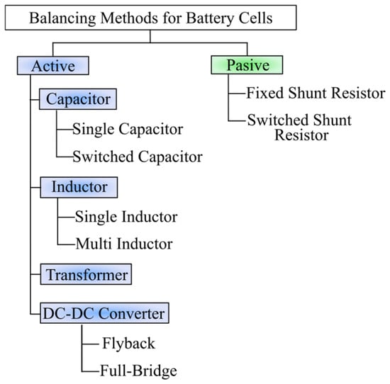
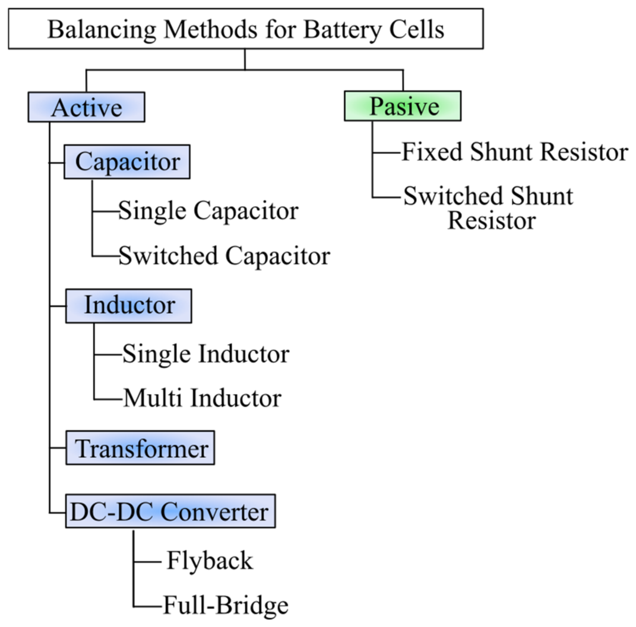
Figure 2 presents several variants of the passive and active strategies used to balance the cell voltage in battery packs. The section on active methods shows that the balancing strategies employ capacitors, inductors, or DC-DC converters. Meanwhile, with passive methods, the most convenient strategy leverages the variable or switchable resistance, which allows the voltage in the cells to be equalized by controlling the resistance [17].
Figure 2.
Methodology for cell balancing.
This article presents a battery balancer intended for operation in a six-cell series (6S) module from a 5.6 kWh LiPo battery pack, which comprises 16 modules connected in series, resulting in a total of 96 cells (96S). Voltage balancing is achieved through a passive strategy based on parallel resistor switching, where activation times are adjusted according to each cell SOC, converting excess energy into heat. The major contribution of this work is the achievement of more controlled charge and discharge cycles in each cell of a LiPo battery pack. The implementation of battery cell balancing is a key issue in the electric vehicular industry, as doing so improves the performance of the battery pack while reducing maintenance requirements, and ensuring safe operation for a long time, as concluded in [18]. Such processes keep voltage levels properly balanced, thereby preventing cells with a high SOH level from degrading prematurely, for which passive balancing is considered the most effective, as mentioned in [18]. The remainder of this paper is organized as follows: First, the proposed battery pack is briefly described, along with the advantages of the passive strategy and a maximum estimate of the heat generated when using this method. Second, the design guidelines of the prototype are described, which incorporate balancing modes designed to minimize heat generation and optimize energy usage through the implementation of operation intervals intended for before and after battery pack charging. Experimental results and numerical estimates are compared to validate the operating principle described in the first section, verifying the balance with the 6S modules. Finally, this article concludes with a summary of the most relevant achievements, along with potential pathways for future research.
2. Materials and Methods
2.1. Battery Pack Proposed
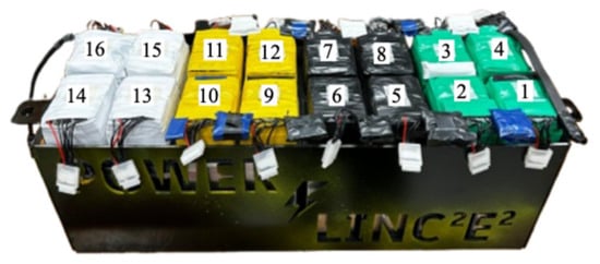
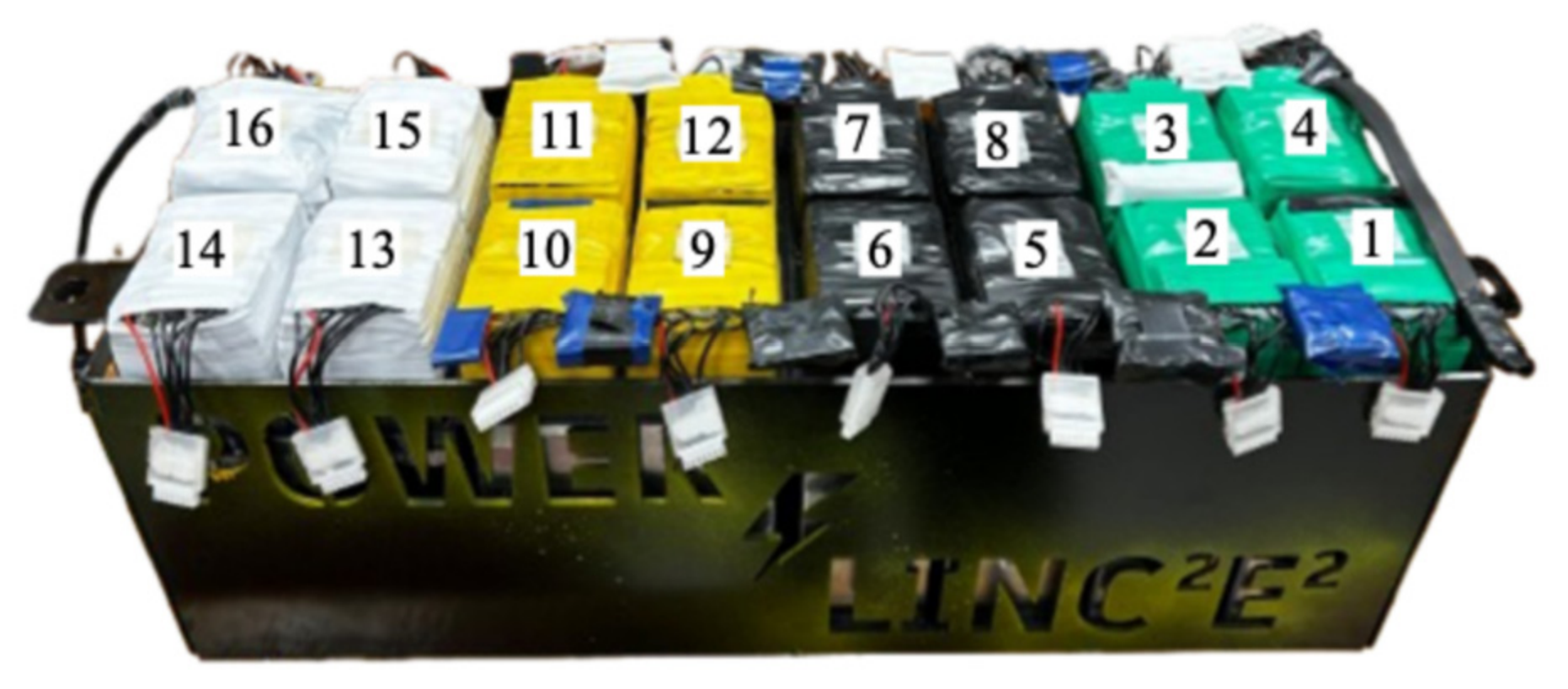
Rechargeable power systems, such as battery packs or supercapacitors, are implemented in transportation electrification [19]. In this paper, a passive balancing system is intended to operate a 5.6 kWh battery pack shown in Figure 3, developed for an 83 kW electric motorbike prototype which is being designed under specifications based on international competitions, as reported in [20,21,22].
Figure 3.
Photograph of the proposed battery pack. Each six-cell module of the battery pack is numbered for easy identification.
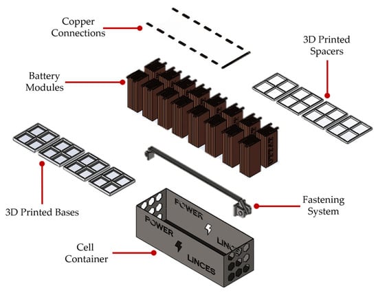
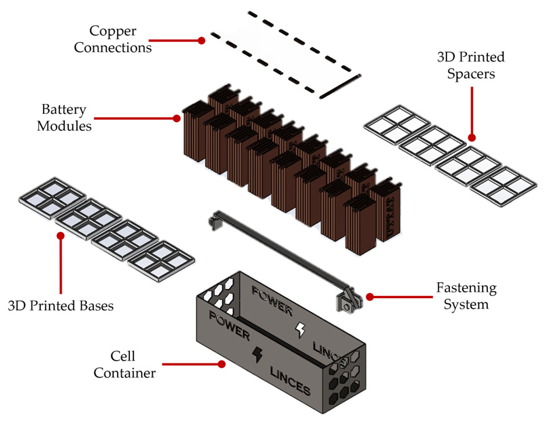
Figure 4 shows a 3D-exploded view of the battery pack used in this work. The battery pack shown in Figure 3 and Figure 4 was assembled with 16 modules, each of them comprising six pouch-type cells, leading to a total of 96 LiPo cells, whose electrical characteristics exhibit favorable performance and high gravimetric energy density [23,24]. Table 1 summarizes the electrical specifications of each cell used in this battery pack.
Figure 4.
3D-exploded view of the battery pack assembly.
Table 1.
Technical specifications of LiPo cells.
The photograph in Figure 3 also shows the personalized metal structure for containing the 96 LiPo cells of the battery pack. This metal container was designed using a 12-gauge galvanized metal sheet. The out-of-the-box dimensions of the pack are 0.2 × 0.6 × 0.22 m. In fact, the 3D-exploded-view drawing of the constructed battery pack was used to analyze the mechanical challenges encountered during the assembly process. In the same figure are displayed the 3D-printed parts that were utilized in the bottom for maintaining the position of all cells and the copper connectors properly insulated. Moreover, this battery pack will be used in a further integration of an electric motorbike with characteristics similar to those of a mid-range internal-combustion-engine racing bike reported previously in [25,26,27].
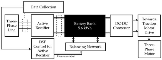
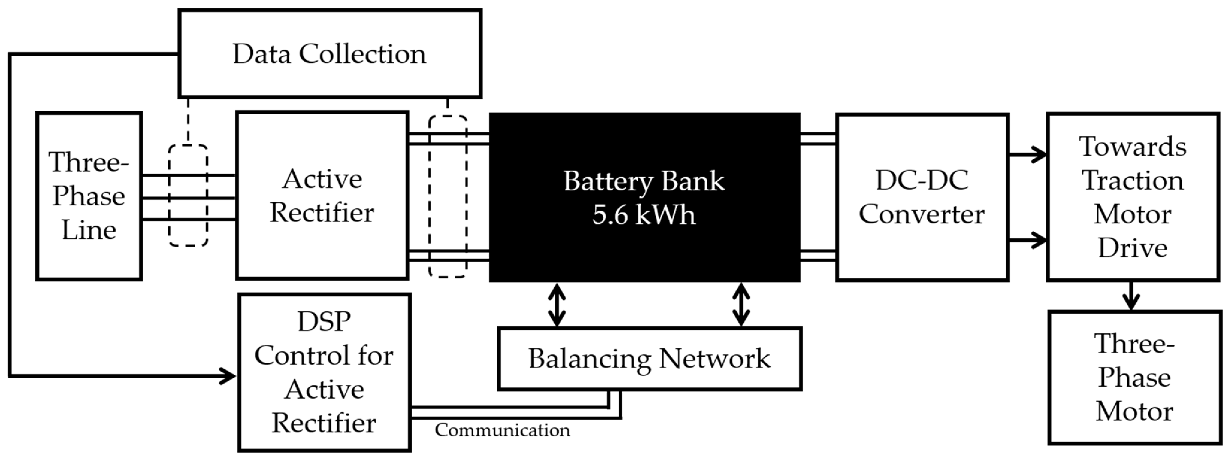
Finally, Figure 5 depicts a block diagram of a proposed set of components for electrification transportation. This includes charging components, the active rectifier, and the battery pack, along with other subsystems, such as DC-DC converters, the motor controller, and the electric motorbike prototype, amongst others, which are beyond the scope of this article; they are intended to be integrated into a single system to achieve a certain level of cell balancing during charging.
Figure 5.
Block diagram of a proposal for electrification transportation.
2.2. Passive Balancing Circuit Design
The aim of this research is to design a passive balancing circuit for each six-cell module contained in the battery pack presented in the previous section, operating at any voltage level within the series array to which it is connected, whether it is module 1 or module 16. In fact, the method selected for this purpose was the Switched Shunt Resistor (SSR), which is a method that has been little studied due to its disadvantages, but which can be applied to balance BESS systems with a larger number of cells [28,29,30]. However, the heat generated by these resistors must be managed appropriately, by calculating the amount of heat generated in each operating mode of the battery balancer and minimizing the amount of energy being dissipated as heat.
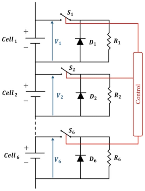
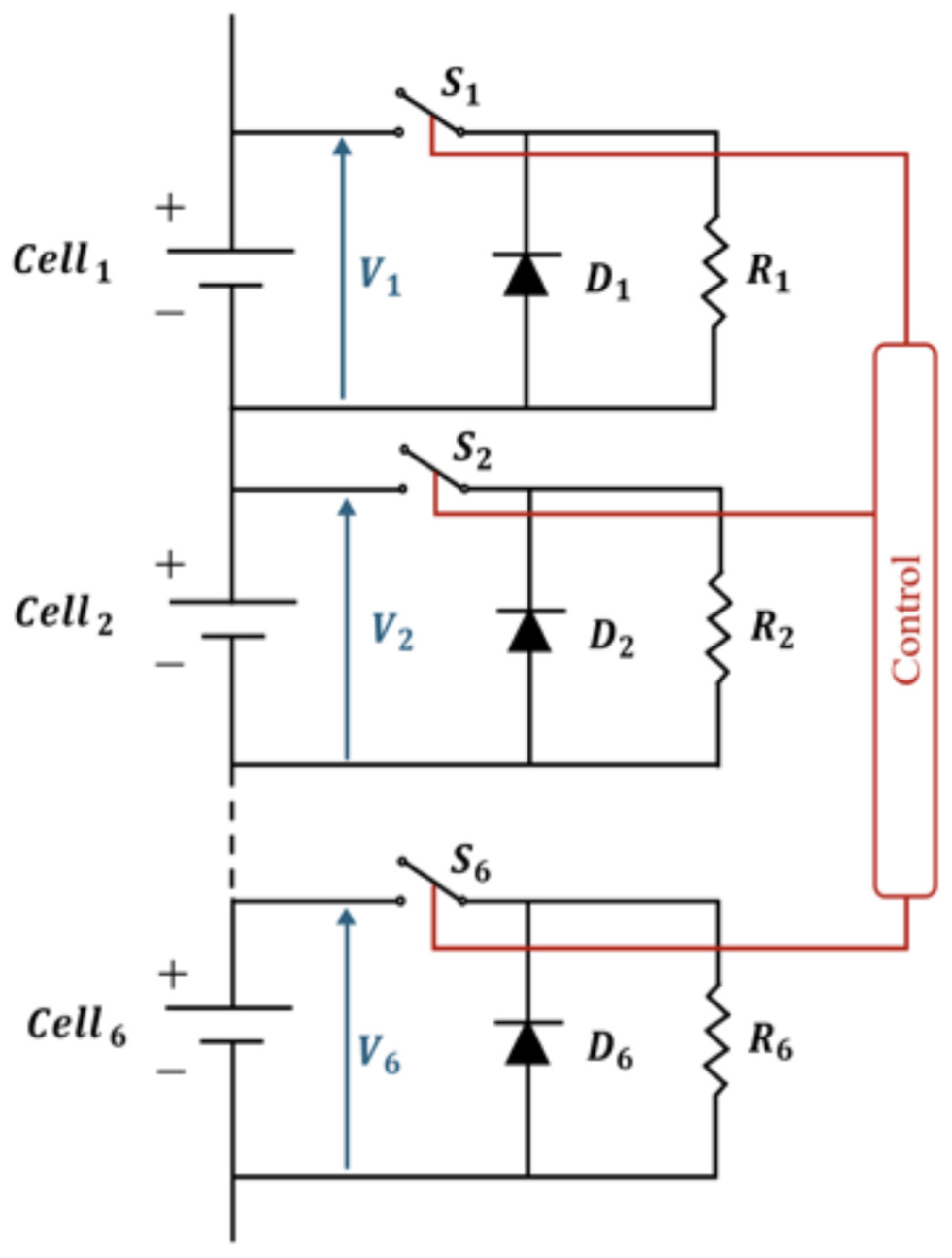
The SSR system used in this research is presented in Figure 6, where six LiPo cells, labeled from Cell1 to Cell6, are shown connected with the shunt resistors, ranging from R1 to R6, which are operated through six switches, S1 to S6, implemented by transistors. In this method, the balancing circuit simply closes switches of cells identified as having excess charge. The SSR system was constructed using TIP41C transistors for switches S1 to S6; these transistors were operated in the cutoff and saturation region. Additionally, six freewheeling diodes were implemented by six MUR420 ultrafast diodes.
Figure 6.
Electric diagram for the SSR proposed.
Operation Modes
The prototype implements a multi-scenario operational framework. These modes match the operational demands of the 83 kW electric motorcycle and the physical constraints of the LiPo pouch cells:
- Mode 1, post-charge (Vref = 4.20 V):
This mode may be activated immediately upon completion of the charge cycle to balance any residual voltage at peak pack potential. The programming code strictly limits cell voltages to 4.20 V, keeping them securely below the manufacturer’s absolute critical degradation threshold, around 4.25 V. Serving as an active protection subsystem, it prevents localized overcharging.
- Mode 2, pre-charge (Vref = 2.75 V):
This mode in intended to operate before the fast-charging process. Due to manufacturing variations, LiPo pouch cells could exhibit different internal resistances, potentially leading to thermal and voltage imbalances during high-current fast charging (e.g., at 10 A). The algorithm initializes by discharging all cells to a nominal low threshold of 2.75 V. This pre-charge conditioning step is used to accomplish a more consistent initial voltage level across the cells before fast charging processes. Although this approach may potentially contribute to improve cell management during the subsequent charging phase, its effects on current distribution, thermal stress, and prevention of premature overvoltage conditions require further experimental validation.
- Safe storage mode (Vref = 3.8 V):
This configuration targets prolonged periods of vehicle inactivity or battery pack transport. Storing LiPo cells at maximum charge (4.25 V) or severe discharge (2.75 V) triggers accelerated chemical degradation of the polymer electrodes and drives capacity fade. This mode selectively discharges and balances cell potentials to the optimal safe storage threshold of 3.80 V, which is specified by the manufacturer. Furthermore, this scenario provides the empirical baseline for long-term thermal characterization of the external dissipating chassis.
Table 2 lists the operating modes for the passive balancing system proposed, showing the modes, the operating range, the excess voltage difference, and the average current for each operating mode. In fact, the highest excess voltage difference occurs during a full cycle of use; meanwhile, in the post-charge mode, this difference may be neglected, since the difference is around 0.03 V in this mode.
Table 2.
Proposed operation modes for the passive balancing system.
2.3. Prototype Construction
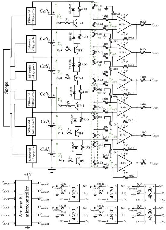
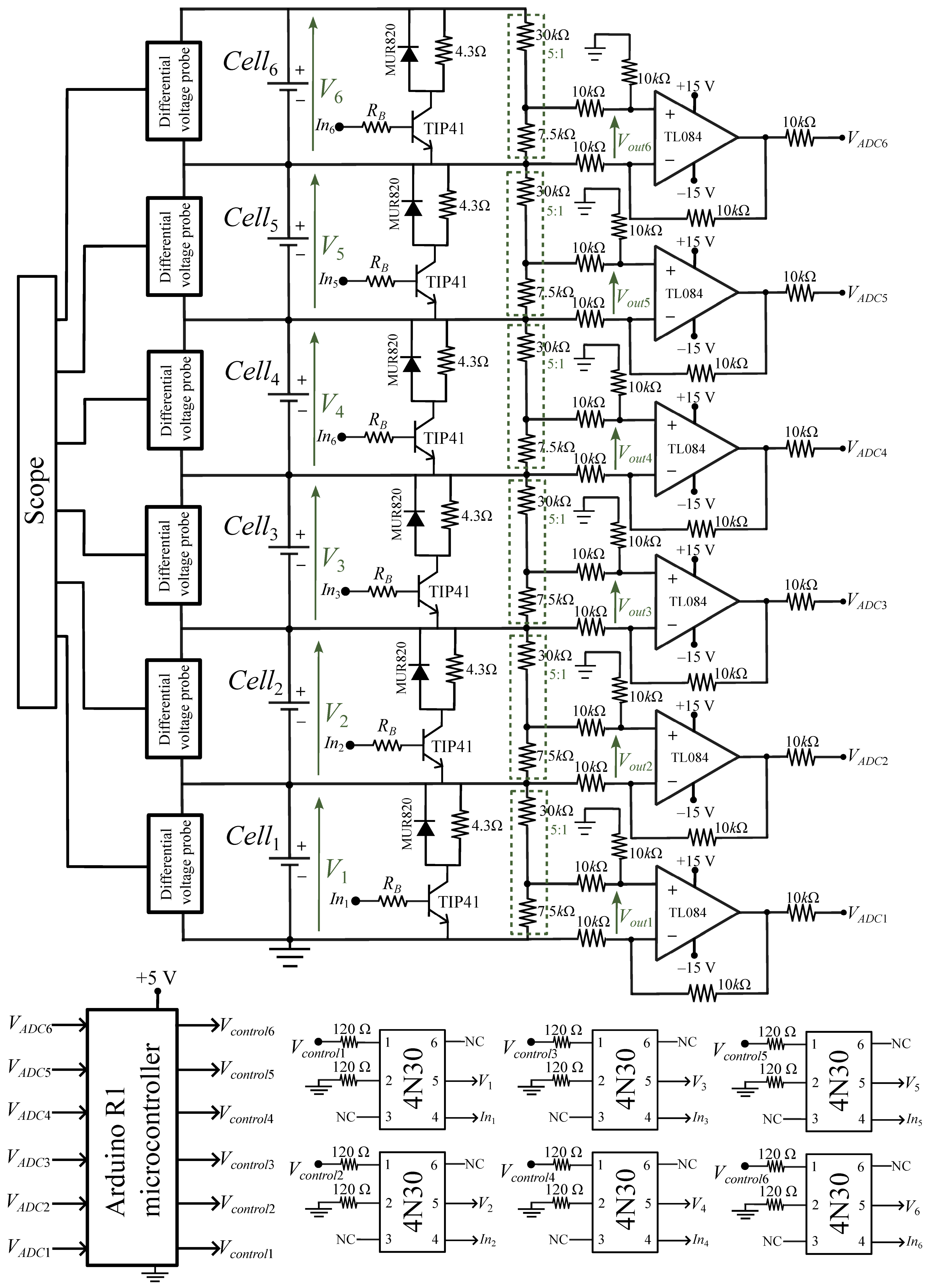
The electrical diagram proposed for the prototype of the SSR system is shown in Figure 7. Figure 7 depicts the implementation of the SSR for any 6S module in the battery pack, whose design is divided into two main parts: the control stage and the power circuit. Firstly, a 4N30 optocoupler was utilized for ensuring isolation between the power and control stages. The control signals used in the bases of each transistor were implemented by an Arduino GIGA R1 microcontroller, which was used as a reference level for the sensors and was powered by an external 5 V voltage supply connected to the USB-C port in a PC.
Figure 7.
Electrical diagram for the SSR.
In addition, six FZ0430 voltage sensors were used to obtain the voltages of the six cells in the module, labeled as V1 to V6, as shown in Figure 6. Each sensor is formed by a resistive voltage divider consisting of two resistors with nominal values of 30 kΩ and 7.5 kΩ. These resistor values yield a nominal voltage division ratio of 5:1, providing an output voltage of 0.85 V when the input voltage reaches 4.25 V.
Table 3 shows the specifications of the FZ0430 voltage sensor used in each cell in the module for obtaining V1 to V6, as proposed in Figure 6. To assess the suitability of different ADC resolutions available in the microcontroller, 10-bit and 12-bit configurations were considered based on the post-charge mode, which exhibits the smallest hysteresis window, approximately 50 mV between cell voltage levels, as reported in Table 2. In this operating mode, the sensor output voltages are 0.850 V and 0.560 V, corresponding to a difference of 29 mV. This voltage difference highlights the need for an ADC with sufficiently resolution. Assuming a 3.3 V reference voltage, a 10-bit ADC provides a theoretical voltage step of approximately 3.22 mV at the ADC input, whereas a 12-bit ADC provides a step of approximately 0.806 mV. Therefore, a 12-bit ADC is suitable for this application because this resolution offers finer voltage discrimination without requiring the additional resolution of a 16-bit ADC, which may introduce unnecessary implementation complexity. Moreover, six operational amplifiers were configured as differential amplifiers with a unitary gain, and the output of each operational amplifier was connected to the analog inputs of the microcontroller. Meanwhile, six digital outputs from the microcontroller were used for turning on the transistors. Finally, six AP031 differential voltage probes from Teledyne LeCroy were utilized for measuring the responses during operation of the system.
Table 3.
Technical specifications of FZ0430 voltage sensor.
The power circuit is the operator of the transistors. For these estimations, a current is required in the collector when the resistors of the SSR are used. The operating values for the balancing operation modes with an R = 4.3 Ω are listed as follows:
- Average current of Mode 1, post-charge, is 0.98 A.
- Average current of Mode 2, pre-charge, 0.70 A.
- Average current of the storage mode = 0.93 A.
The currents in the transistor are given by the following equation:
And the current IB from the above equation must be solved in the following equation:
- IB is the base current required to turn on the transistor.
- IC is the current flowing through the resistor in Mode 2 ( ).
- β is value DC current gain. For the TIP41C transistor under these operating conditions, according to the graphs in the data sheet, the DC current gain is around 50.
Substituting the values into (3) yields IB:
Retrieving RB by analyzing the voltages in the power mesh and solving for the following:
- RB is the resistance required to supply the current and turn on the transistor.
- is the minimum voltage of the LiPo cell in the series array.
- is the collector–emitter voltage of the 4N30 optocoupler when it is turned on; the voltage under these conditions is 0.3 V, since it behaves as if it were a diode.
- is the base–emitter voltage of the TIP41C transistor when it is turned on. The voltage in this state is 0.7 V, as this is the turn-on voltage for NPN bipolar junction transistors made of silicon.
Substituting the values into (5) yields RB, which is used to determine the resistance value required for each balancing board in order to implement the SSR circuit:
A commercial RB = 120 Ω was used in the implementation of the prototype for verifying that it would operate in the saturation region:
The saturation current is obtained with (7):
Using β = 50 by the datasheet in (8) yields
In order to ensure that the transistor is in the saturation region, the following condition must be addressed:
2.4. Thermal Generation Analysis
Passive voltage equalization converts excess cell electrical energy into thermal energy via Joule heating. The instantaneous heat generation rate () within each shunt resistor is governed by the following:
where I(t) is the time-variant balancing current, and R(T) is the shunt resistance as a function of temperature. For steady-state thermal evaluation, the power dissipation per active channel (Ploss) is determined using the average balancing current () and the nominal power resistance ():
The cumulative thermal energy dissipated by a single shunt resistor over a complete balancing cycle of duration, tb, is integrated as follows:
To eliminate thermal coupling within the energy storage system, the passive balancing circuitry is designed as a modular architecture that is physically external to the main battery bank enclosure. This spatial decoupling ensures that the thermal effect generated by the shunt resistors and adjacent electronic components does not contribute to the internal thermal load of the cells. Under this design constraint, an individual balancing channel was experimentally evaluated to characterize its heat-dissipation behavior and establish a baseline for the multi-channel system. The effective thermal resistance from the resistor junction to the ambient air (Rθ,ja) under free natural convection conditions is defined by the following:
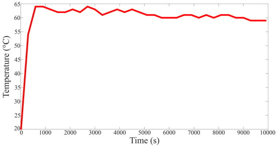
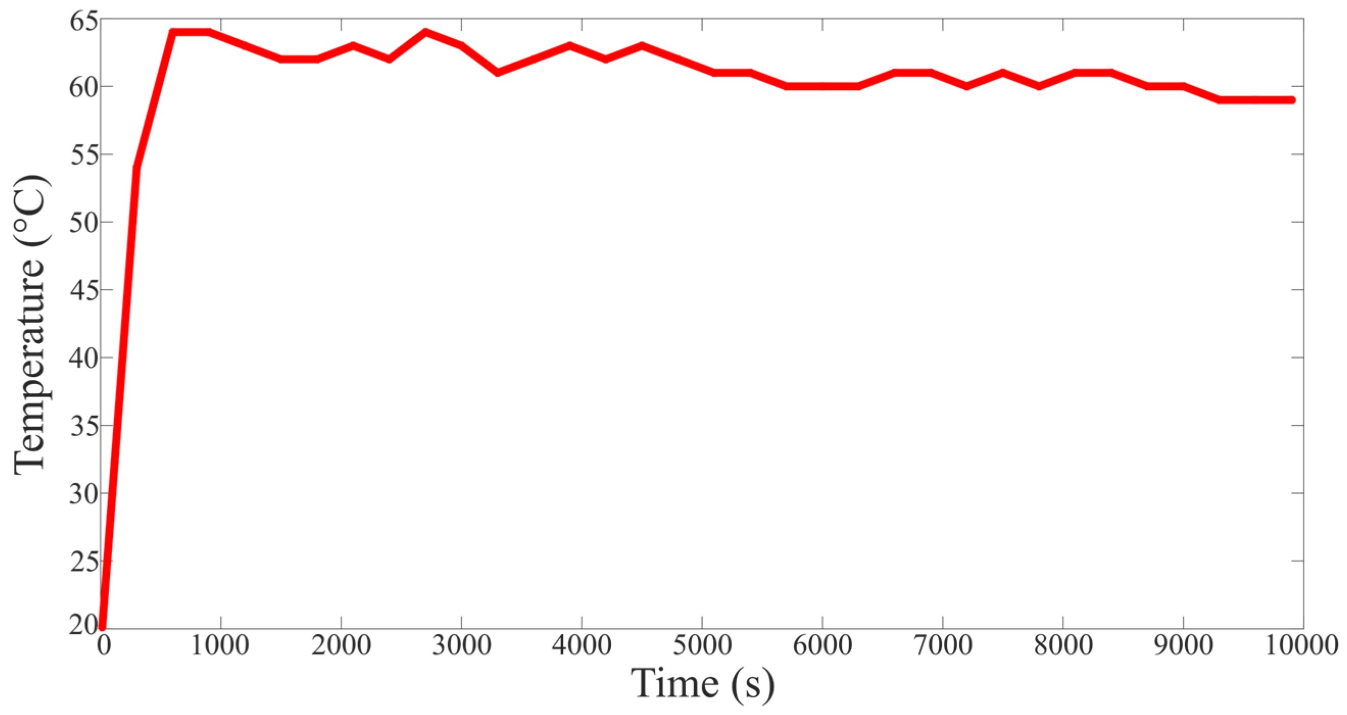
Operating at a controlled ambient temperature (Tamb = 25 °C), the experimental thermal curve illustrated in Figure 8 captures the transient response and peak surface temperature (Tsurf) of a single resistor, which stabilizes at 64.3 °C after approximately 1000 s. This empirical boundary condition establishes the individual thermal resistance from the node to the atmosphere at
Figure 8.
Temperature for the discharge test of one resistor.
Regarding the thermal response of the cells, the localized heat generation produced by a 1 A balancing discharge does not introduce a critical thermal aversion within the lithium-ion polymer (LiPo) matrix. Because the 4.3 Ω resistance restricts the initial peak current to 0.988 A (I = 4.25 V/4.3 Ω) under the real peak cell potential. This variation is explicitly attributed to the initial degradation state of the experimental pouch cells, which limits full charge retention at 100% capacity relative to the nominal specification plate value (4.25 V) due to natural aging. Furthermore, cells with distinct initial voltages were intentionally selected to establish a severe voltage unbalance condition, thereby providing a robust stress test to evaluate the dynamic response of the architecture.
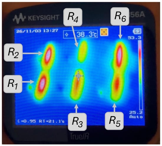
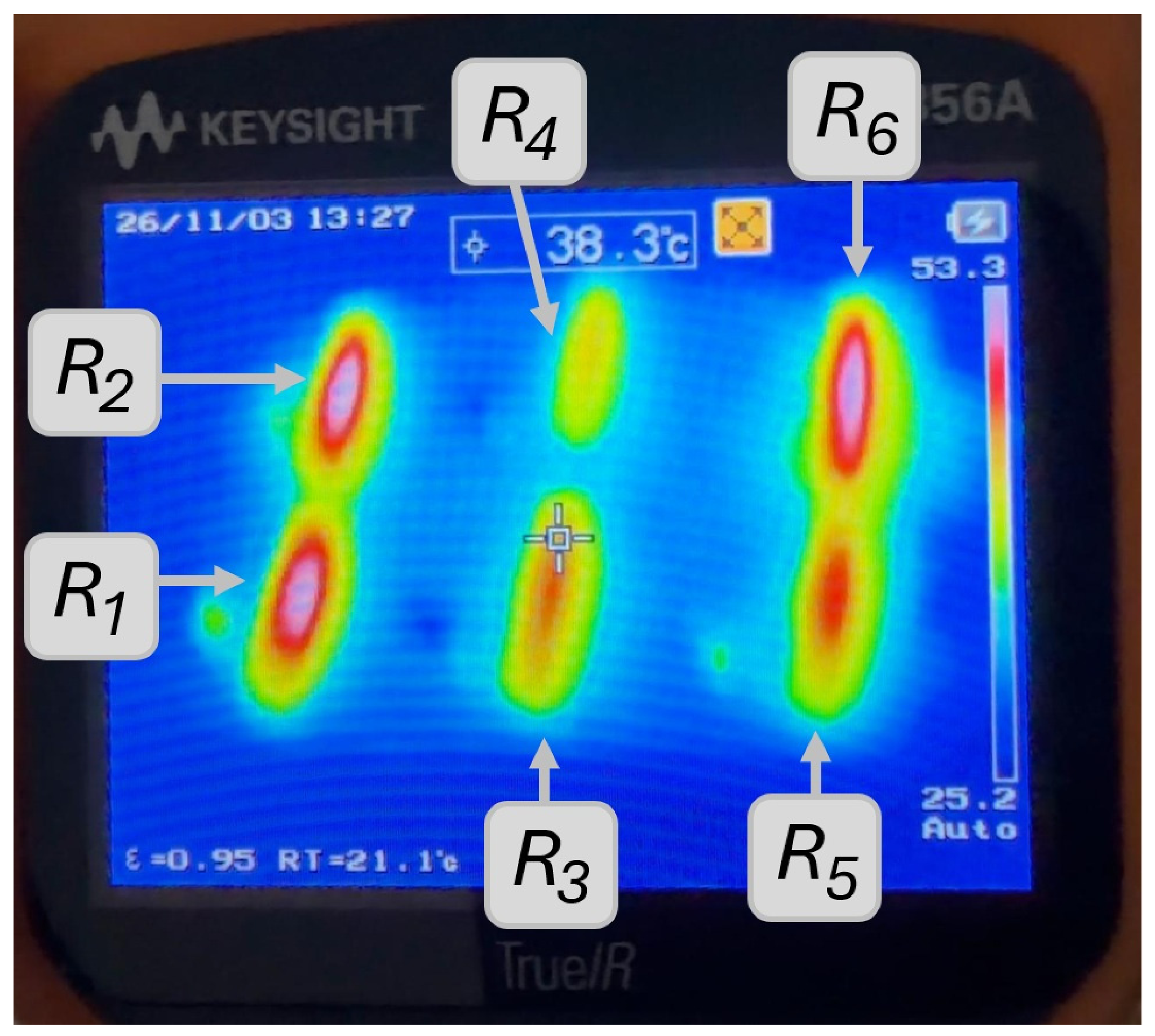
For further experimental validation, an IR thermal capture is reported in Figure 9, where the temperature in each shunt resistor was around 53.3 °C during operation in Mode 3. This mode was selected in order to display the six resistors operating by a period, ensuring temperature convergence. However, as shown in Figure 9, the thermal IR reveals the initial unbalance between the cells, because the resistors operate independently. In fact, in this experiment, the R4 presented the lowest temperature because it was around the final voltage faster than the other shunt resistors.
Figure 9.
IR thermal capture for the discharge test of the system.
This current configuration establishes a conservative C/16 discharge rate relative to the nominal 16 Ah cell capacity. Furthermore, a maximum discharge current of 1 A corresponds to a very low C-rate of 0.0625 C (1⁄16 C). This condition dismisses any significant thermal stress or heat generation inside the battery cells, isolating the heat management strictly to the external balancer cabinet. Finally, the thermal stress in the TIP41C transistor may be computed by power losses. The power losses in TIP41C transistors, PBJT, may be computed in the saturation region with IC = 1 A, while the TIP41C transistor exhibits a collector–emitter saturation voltage of VCE(sat) = 0.2 V (according to its datasheet). Therefore, each transistor generates a maximum heat power of
Considering a simultaneous operation of the six channels, the transistors would generate a total of 1.2 W per module. The amount of power losses is substantially reduced for representing a heat source in the circuit when each transistor can handle around 60 W according to the manufacturer.
2.5. Proposed GUI
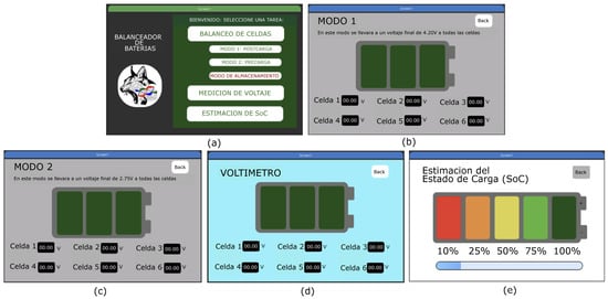
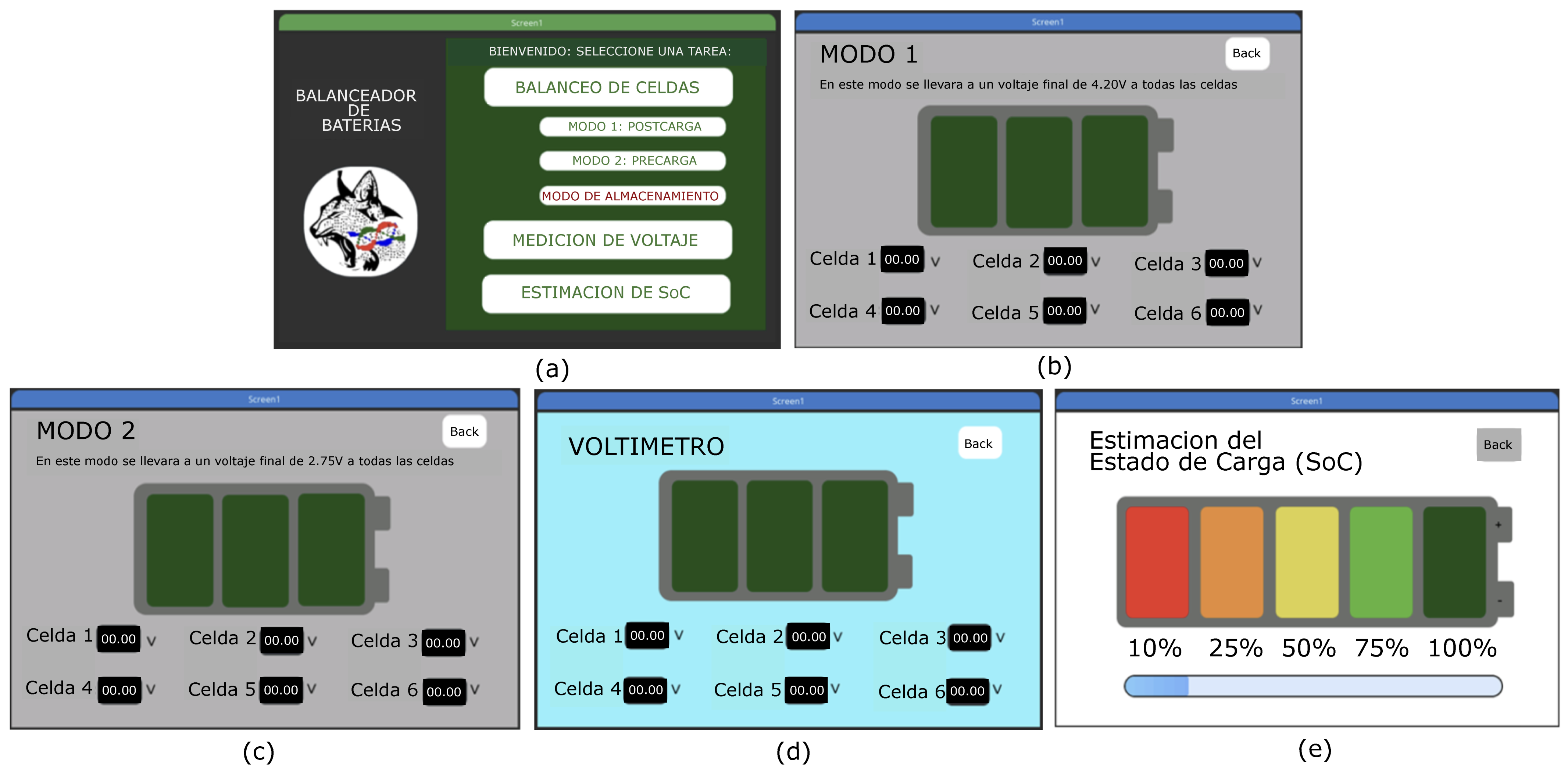
The control interface intended for using the SSR system is a Graphical User Interface (GUI), with a real time selection among these three scenarios and the proposed modes by the user. This interface was developed in the Square Line Studio program [31,32,33], and then the programming code was transferred to the Arduino GIGA R1 Wi-Fi [34]. Three different options were programmed for the home screen of the GUI. The first one shows cell balancing, and three options were configured: Mode 1, post-charge; Mode 2, pre-charge; and storage mode. The second one presents a section showing voltage measures, i.e., using the balancer as a real-time voltmeter. Finally, the last one is a function for estimating the SOC through programming.
Figure 10 shows pictures of the interfaces programmed for the balancer: (a) shows the start window for selecting the device operating mode; (b) displays the Mode 1 window, which presents the operating interval for post-charging, where an equalization at 4.20 V is operated; (c) shows the Mode 2 pre-charge window, which activates the resistors of the cells that are above 3 V and up to 2.75 V; (d) shows the voltmeter window for checking the voltage of each cell in real time; and, finally, (e) shows the SOC estimation window, which shows the charge percentage using a bar and an image—this was programmed into the microcontroller according to certain voltage levels described above.
Figure 10.
Windows of the modular passive balancer interface.
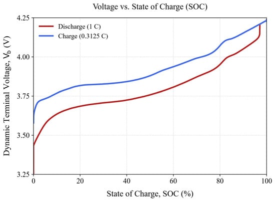
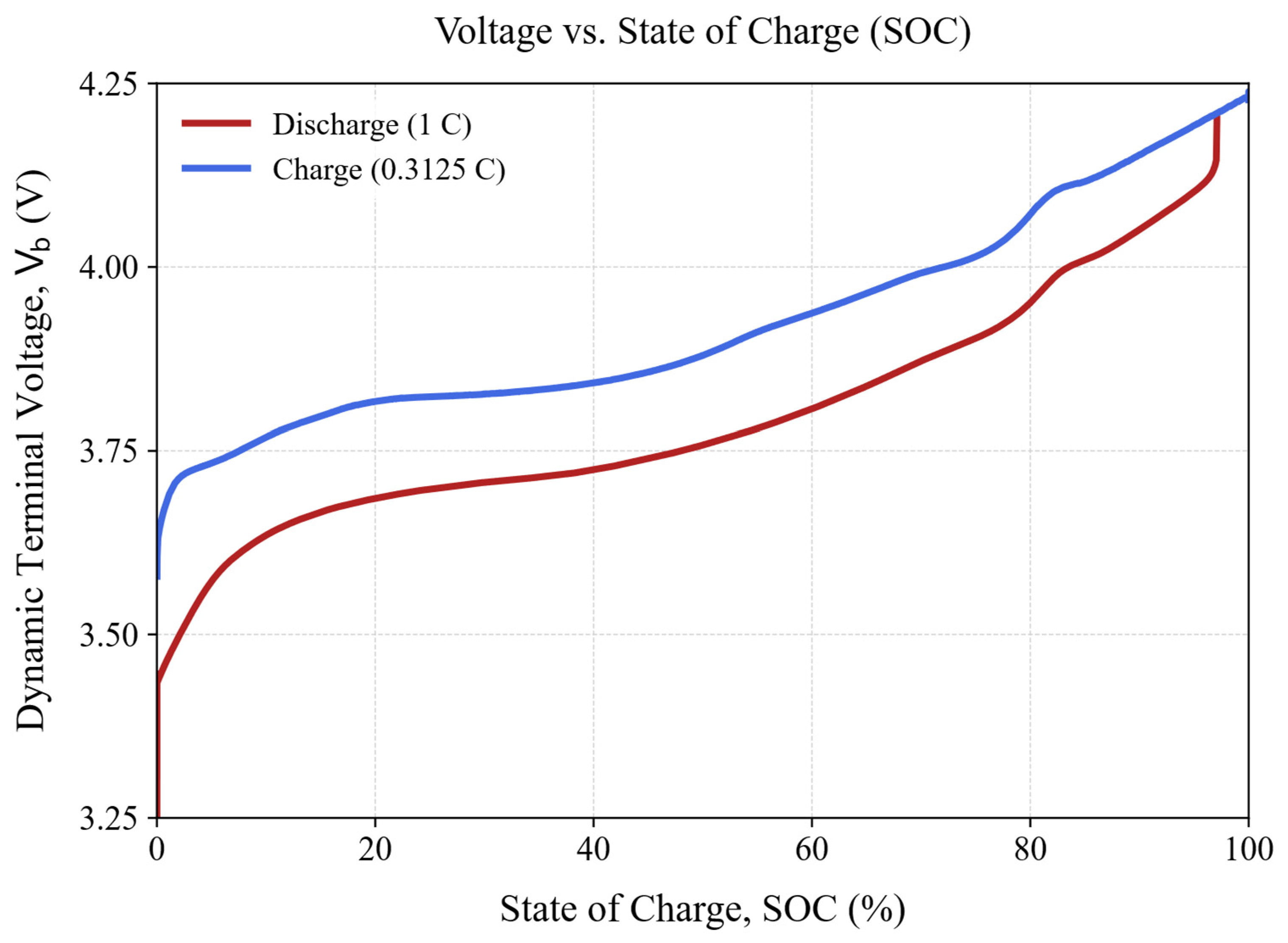
To ensure precise state estimation within the firmware and avoid the severe inaccuracies induced by conventional linear interpolation approximations, an approximate SOC indicator was developed using an electro-chemical look-up profile, specific to the LiPo cells used in this research, based on cell characterization trials. Figure 11 illustrates the dynamic terminal voltage (Vb) as a non-linear function of the SOC, benchmarked under a 1 C discharge rate and a 0.3125 C charge rate. The integrated dataset tabulates these empirical operating boundaries, providing the deterministic voltage-to-SOC lookup references implemented in the microcontroller code to synchronize the multi-scenario balancing thresholds with the real electrochemical state of the LiPo pouch cells. Also, Table 4 shows the values for programming the approximate SOC indicator using the voltage in 1C discharge and the discharge curve shown below.
Figure 11.
Voltage vs State of Charge (SOC).
Table 4.
State of Charge (SOC).
2.6. Description of the Final Prototype
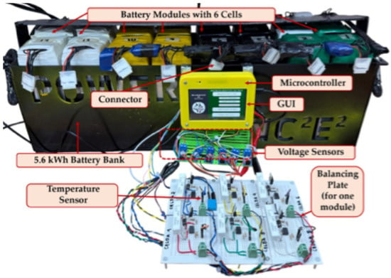
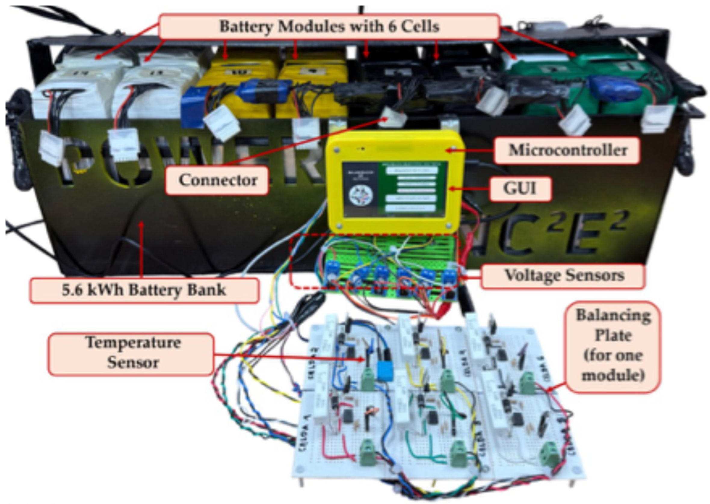
Figure 12 presents the final SSR prototype built in the laboratory and used for experimental validation, including the 5.6 kWh battery pack.
Figure 12.
Photograph of the prototype.
3. Experimental Results
3.1. Mode 1, Post-Charge
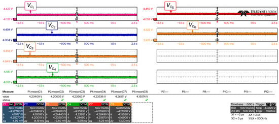
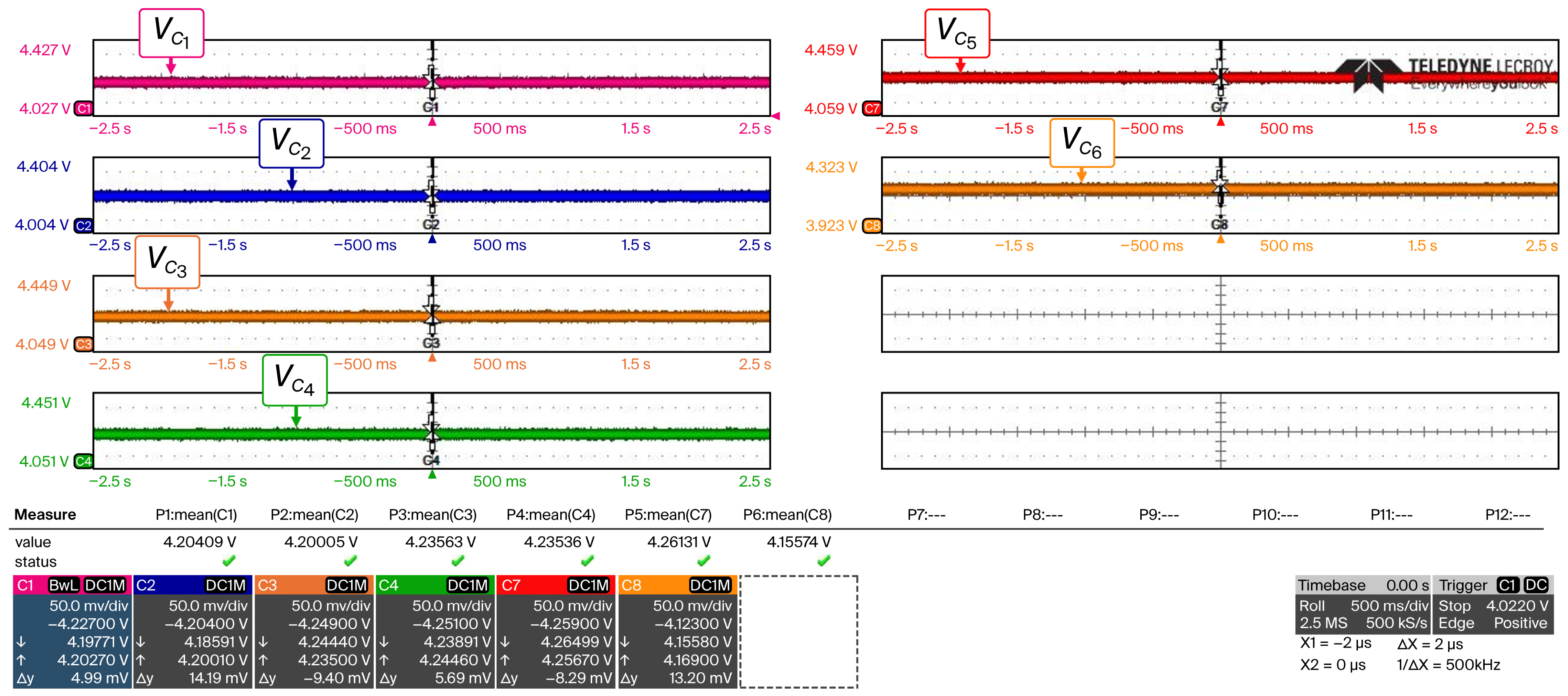
For the performance evaluation of the passive balancing system in Mode 1, post-charge, experimental testing was conducted on module number 6 of the 16-module battery pack. The initial open-circuit terminal voltages revealed a high voltage unbalance across the series-connected cells: V1 ≈ 4.21 V, V2 ≈ 4.21 V, V3 ≈ 4.23 V, V4 ≈ 4.23 V, V5 ≈ 4.26 V, and V6 ≈ 4.15 V. Figure 13 shows the initial voltages waveforms of a module in the series-connected 5.6 kWh battery pack.
Figure 13.
Waveforms of the voltages of the 6S under initial conditions of the balancing test.
The potential of Cell 5 was around 4.26 V, exceeding the maximum allowable safe operational limit of 4.25 V specified by the manufacturer and Table 2, and thus placing the cell in a critical overcharge zone with a severe risk of accelerated degradation. Nevertheless, this real desynchronization state was adopted as a stress test to validate the protection capabilities and response time of the proposed SSR system. Instead, Cell 6 remained undercharged at 4.15 V; its corresponding switch, S6, was maintained in the off state throughout the test, demonstrating the selective control precision of the system.
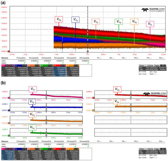
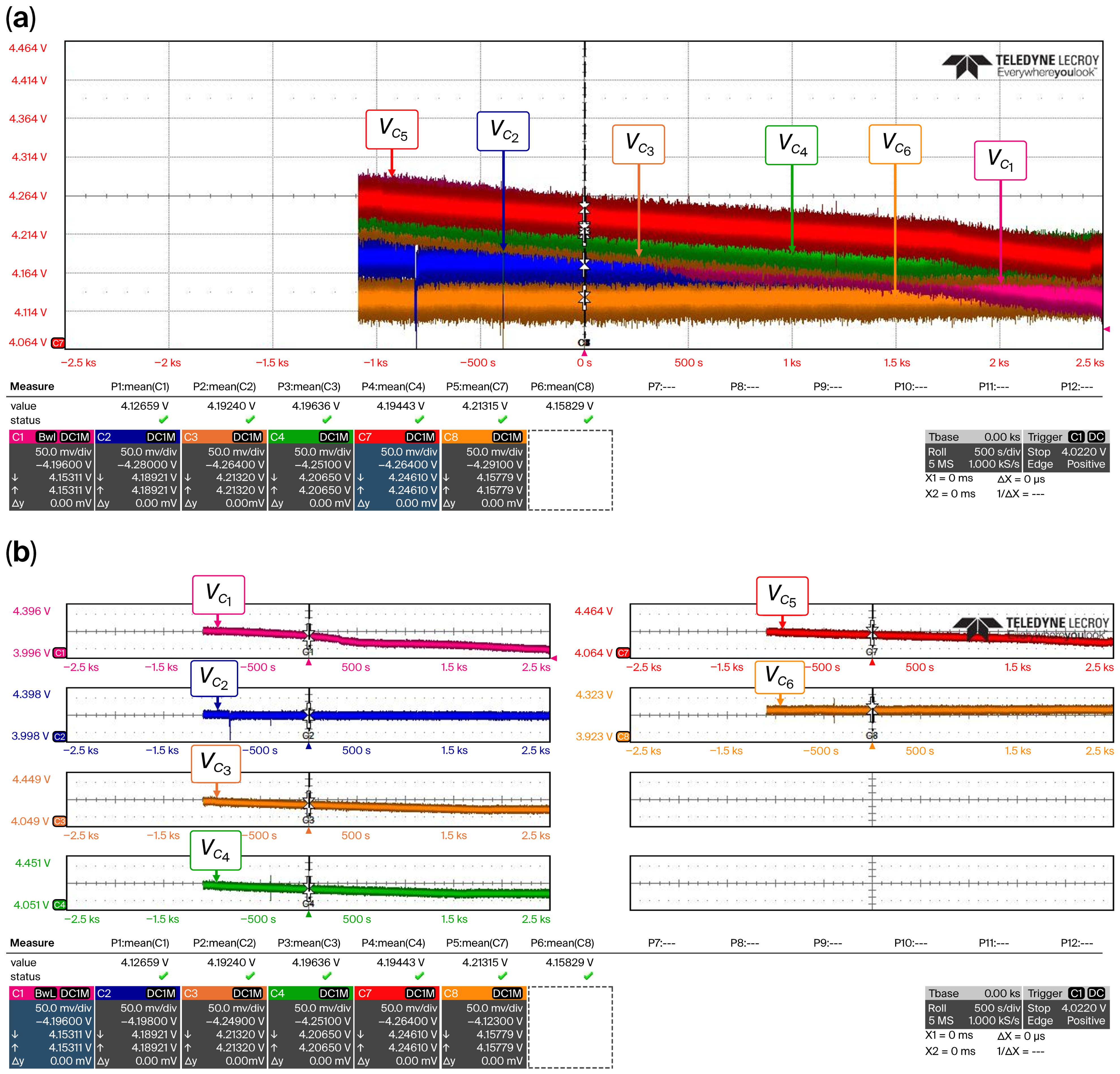
Figure 14a shows the experimental waveforms of the balancing process in Mode 1 of the prototype. This result shows the corresponding balancing of the six cells: four out of six cells were maintained between 4.19 V and 4.20 V, while the other two fell below this voltage window; as mentioned above, V6 had a voltage of 4.15 V, so the prototype was not activated for this cell. For cell 1, the voltage, V1, was activated in one part of the process and then turned off. The voltage of this cell continued to drop on its own, and for this reason, an unusual discharge curve is presented for Cell 1. Figure 14b presents the split curves. The total balancing time was 3600 s.
Figure 14.
(a) Experimental waveforms for the balancing process of Mode 1, post-charge; and (b) the balancing process, as shown in 6 different plots.
3.2. Mode 2, Pre-Charge
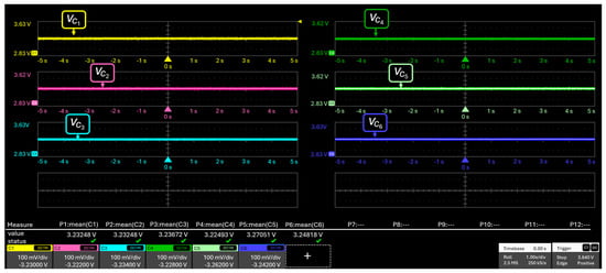
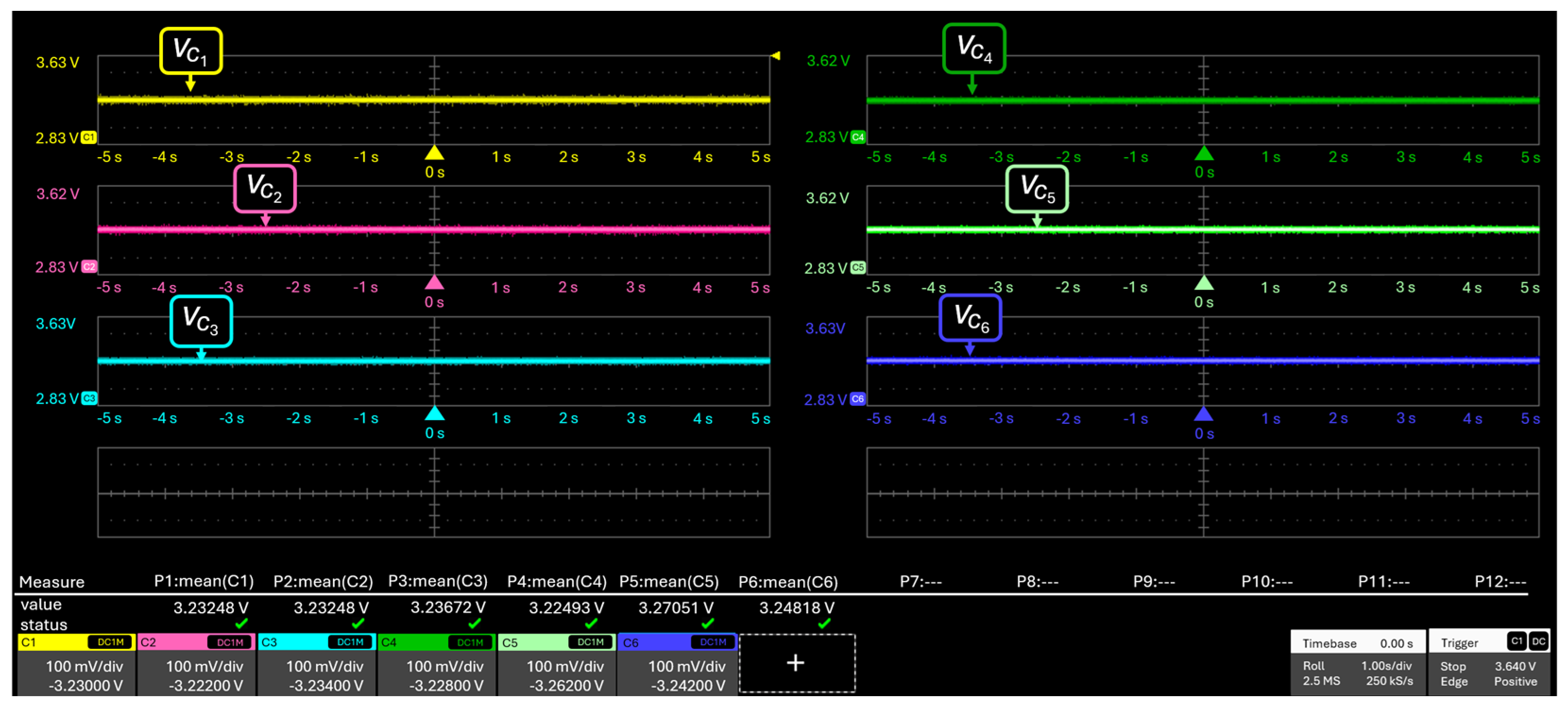
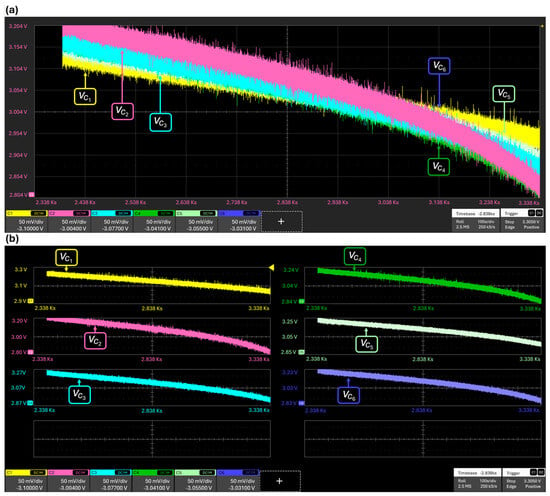
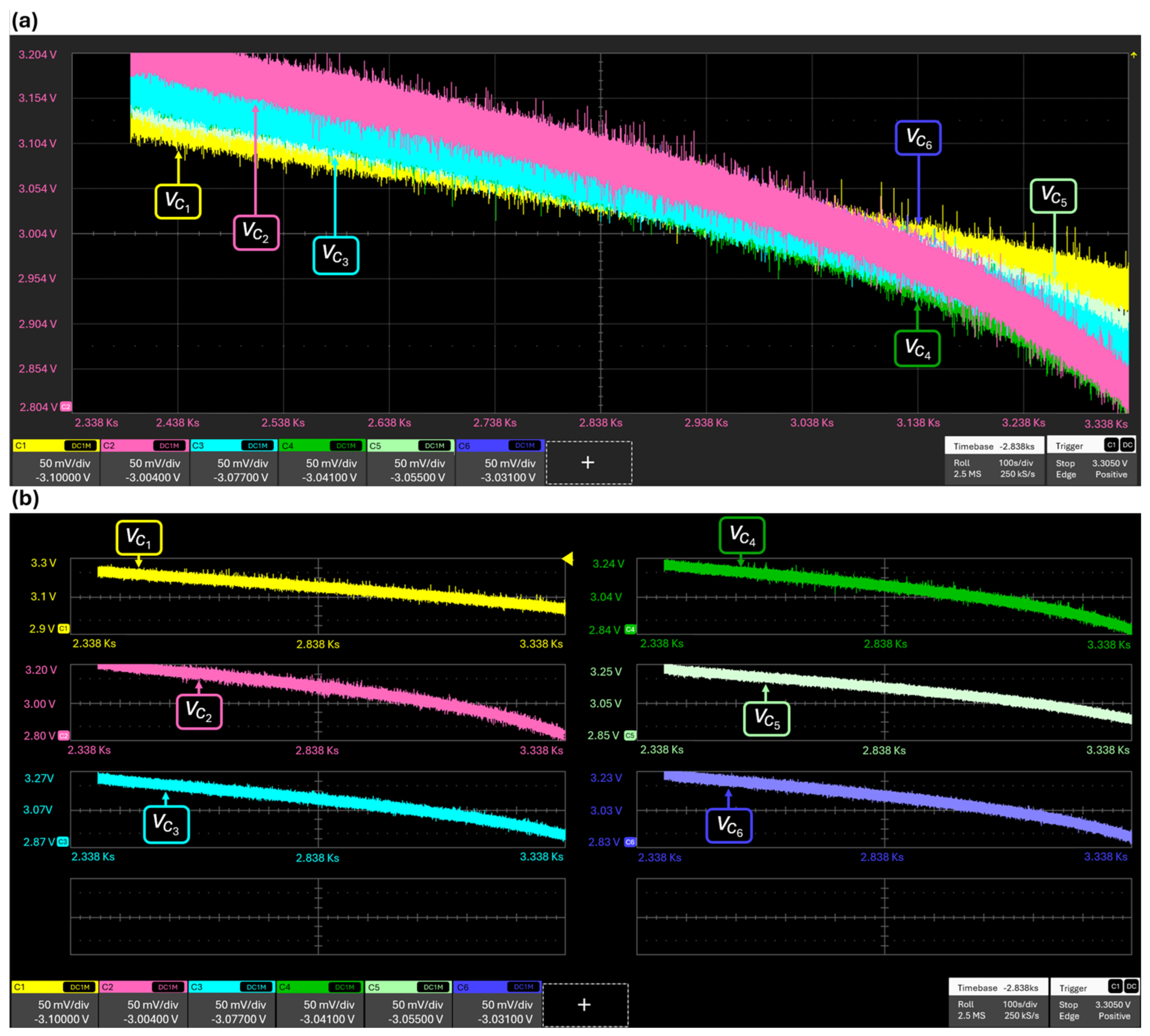
Figure 15 displays the initial conditions used for the Mode 2, pre-charge. In fact, the open-circuit terminal voltages revealed a low unbalance due to all the cells exhibited around 3.2 V between their terminals. Figure 16 presents the experimental results obtained under the operation of Mode 2, pre-charge. As shown in Figure 16a, Cells 1 to 6 were balanced above 3 V, ensuring the cell levels in the voltage window reference listed in Table 2. For this mode, the voltages of the cells may be balanced to 2.75 V. However, to avoid damages in the cells, the test was configured to reach around 2.8 V, keeping all the cells safe. In this operation mode, the time used for this balancing process was around 1800 s. Figure 16b shows the same results from the scope in split plots for better understanding.
Figure 15.
Waveforms of the voltages of the 6S under initial conditions of the balancing test.
Figure 16.
(a) Experimental waveforms for Mode 2, pre-charge; and (b) experimental results in several plots for visualization.
3.3. Storage Mode
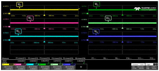
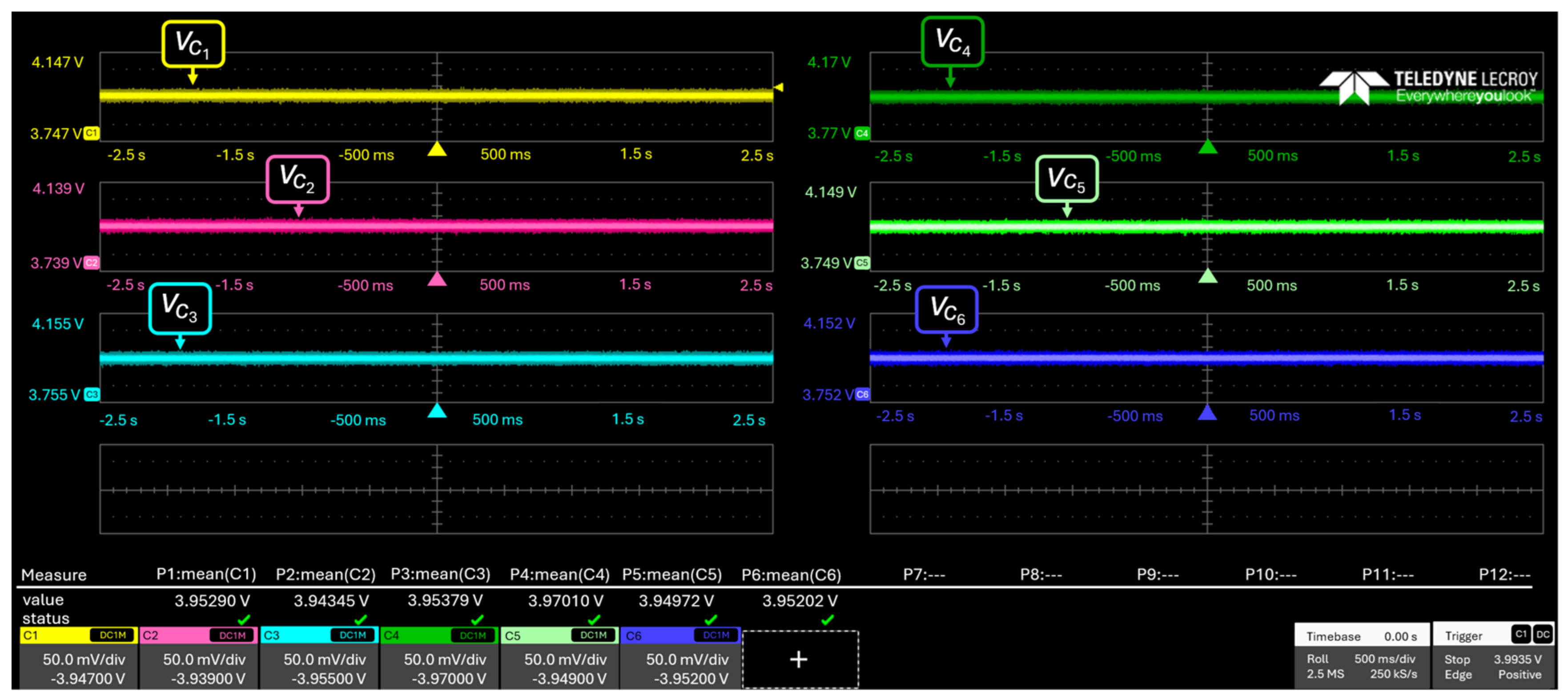
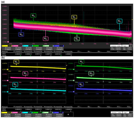
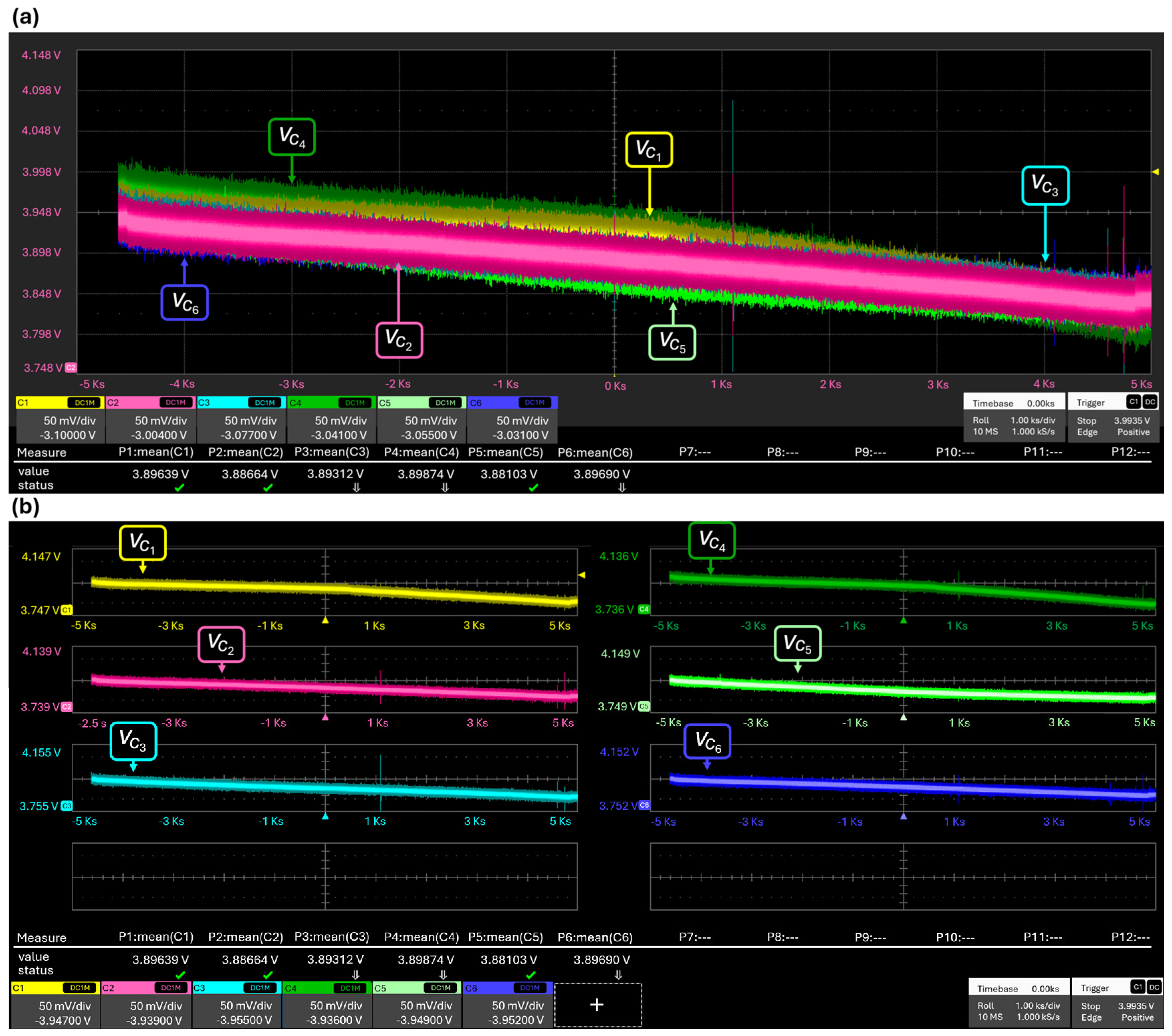
The voltage levels used as initial conditions for the storage mode are shown in Figure 17. As shown in Figure 17, most of the cells presented 3.95 V before the operation of the storage mode. When this mode was operated, all the cells exhibited voltages of about 3.8 V after the balancing period, and the time recorded in this operation mode was approximately 9400 s, equal to 2.6 h, as shown in Figure 18a. Figure 18b shows the same results in split plots for better visualization in the scope.
Figure 17.
Waveforms of the voltages of the 6S under initial conditions of the balancing test in storage mode.
Figure 18.
(a) Experimental waveforms for storage mode, and (b) experimental results in several plots for visualization.
3.4. Results
Table 5 shows the results of each cell in the three operating modes, displaying the initial and the final voltage, together with ΔVmax and the balancing time corresponding to the experimental waveforms obtained in each operating mode. Moreover, the voltage spreads for each mode are presented in the same table. The voltage spread in Mode 1 is reduced, while the voltage spread in Mode 2 is substantially increased. However, the main aim of this mode is achieving a safe discharge of each cell, reaching around 2.8 V, despite revealing a higher voltage spread in contrast to the initial conditions.
Table 5.
Results for the three operation modes.
4. Discussion and Study Limitations
The possibility of implementing a passive balancing network as a subsystem to protect chargers and BMS in order to achieve more controlled charge and discharge cycles is verified. The implementation of a balancing network designed to ensure that the cells operate within low-balancing thresholds is a key issue in the current electric vehicular industry, as it enhances the performance of the battery, pack as mentioned in various sources cited in this article.
Passive balancing has already been applied to various battery chemistries, such as lithium-ion [34] and lithium iron phosphate [35]. It is hypothesized that this prototype could be adapted to multi-chemistry by adjusting the reference voltage (VRef) thresholds within the Arduino GIGA R1 firmware. Thus, the physical platform can be optimized for alternative commercial storage technologies, such as the following:
- Lithium iron phosphate (LiFePO4): Configured with a software threshold for storage conditioning or VRef = 3.65 V: for top-balancing.
- Conventional lithium-ion (VRef = 3.20 V): Programmed with standard thresholds of 3.6 V for low-end conditioning and 4.20 V for post-charge clipping.
Although chemistries are characterized by open-circuit voltage curves with ultra-flat plateaus in their middle operating zones (such as the voltage level of LiFePO4), they may introduce tracking challenges for fine SOC estimation. However, different chemistries also require different SOC behaviors and other approximate indicator, balancing thresholds, and thermal limits, and it is therefore emphasized that this prototype is not directly proportional and that experimental validation is required.
Finally, making an analysis of commercial charging systems for electric vehicles in Mexico City, there are several types of charging stations, broadly divided into two main categories: those found at home and public ones. Both generally have two levels; for home use, there is a Level 1 charger at 120 V (which can charge the car in 12 h) and a Level 2 charger at 230 V (with a charging time of 6–8 h at an approximate power output of 7 kW). Public charging points, on the other hand, offer 240 V fast charging or 480 V ultra-fast chargers [36]. Considering a standard 230 V, 7 kW Level 2 home charger, as this is the most common type in the country, and bearing in mind that, on average, these stations take 7 h to charge and add a further hour for balancing in Mode 1, the vehicle’s charging time would be 8 or 9 h at most when a charging-and-balancing process is implemented.
5. Conclusions
The results of the SSR balancer system for six cells show experimental verification in the prototype for balancing the individual modules in a 5.6 kWh battery pack. The waveforms shown demonstrate the capacity to equalize the voltage of the cells at three modes. For Mode 1, post-charge takes approximately 3500 s, reaching a voltage level of 4.20 V. Nevertheless, in this case, two cells were out of this reference voltage level because of the SOH limits of the operation. In the case of Mode 2, the results exhibited a balance around 2.8 V, where the operation of the module in the pre-charge process was validated with a period of time of approximately 1800 s due to the inherent curve of the LiPo cells. Finally, for the storage mode presented in this research, all of the cells reached around 3.8 V in a long period of time, i.e., about 9300 s. However, this mode could present the largest period of time during the process, becoming relevant for applications in this sort of chemistry.
Furthermore, by quantifying the amount of heat produced by the resistor, we demonstrated that the temperature is not excessively high and that it did not affect the performance of the balancer prototype. It should be noted that the thermal analysis of the resistors was conducted without any type of cooling and still helped to validate and implement it in the six-cell prototype.
The implementation of the GUI made human–machine communication more attractive and made it easier to use the device. The combination of the Arduino GIGA R1 Wi-Fi microcontroller and the Arduino Giga Shield Display was very convenient, as it allows the user to select balancing modes with its touch screen, monitor the balancing process in real time, function solely as a voltage meter for each cell, and estimate the approximate SOC of each module in the battery pack.
The construction and preliminary design of the battery pack was favorable for implementing the passive balancing strategy, as the reconditioning of some cells and the design and construction of a new pack served as a precedent for implementing the balancer under its operating conditions. In addition, the same laboratory is developing various prototypes to validate the 83 kW electric motorcycle, such as a dynamometer to characterize the electric motor, and a charger for the 5.6 kWh bank, which lacked a balancing network. The modular prototype presented can be integrated into this charger as a protection subsystem.
Finally, further research is considered in order to achieve a system that allows for the utilization of excess energy from the cell without the need to dissipate it as heat, as well as quantifying how many additional life cycles at a high SOC this prototype can have.
Author Contributions
Conceptualization, C.-D.T.-U. and N.M.-E.; methodology, I.A.-V.; software, C.-D.T.-U.; validation, C.-D.T.-U., I.A.-V., P.-E.V.-E., and J.F.V.-A.; formal analysis, J.F.V.-A.; investigation, I.A.-V.; resources, I.A.-V.; data curation, C.-D.T.-U.; writing—original draft preparation, C.-D.T.-U.; writing—review and editing, P.-E.V.-E. and J.F.V.-A. visualization, P.-E.V.-E.; supervision, N.M.-E.; project administration, N.M.-E. and S.P.-R.; funding acquisition, N.M.-E. and S.P.-R. All authors have read and agreed to the published version of the manuscript.
Funding
This research was funded by Secretaría de Investigación y Posgrado (SIP) of the Instituto Politécnico Nacional (IPN) grant numbers 20232820, 20241117 and 20261047.
Data Availability Statement
The original contributions presented in this study are included in the article. Further inquiries can be directed to the corresponding author.
Acknowledgments
The authors would like to thank the Secretaría de Ciencia, Humanidades, Tecnología e Innovación (SECIHTI); the Instituto Politécnico Nacional (IPN) of México; the call for innovation by the program “Proyectos de Desarrollo Tecnológico o Innovación Para Alumnos del IPN”; and the LINC2E2 laboratory for their encouragement and academic advice, as well as the support of each researcher that made up this group in the realization of this project.
Conflicts of Interest
The authors declare no conflict of interest.
Abbreviations
The following abbreviations are used in this manuscript:
| LiPo | Lithium polymer |
| EV | Electric vehicle |
| BESS | Battery Energy Storage System |
| SOC | State of Charge |
| SOH | State of Health |
| SSR | Switched Shunt Resistor |
| C | C-rating for charge or discharge |
| GUI | Graphical User Interface |
References
- AIEA. Trends in Electric Car Markets. In Global EV Outlook 2025; IEA: Paris, France, 2025; Available online: https://www.iea.org/reports/global-ev-outlook-2025/trends-in-electric-car-markets-2 (accessed on 10 October 2025).
- Zhussupova, A. The 15 Chinese Car Brands Plotting to Dominate UK Market as Newcomer Overtakes BMW, Mini AND Land Rover. The Sun, 2025. Available online: https://www.thesun.co.uk/motors/36967746/15-chinese-car-brands-to-dominate-uk-market/ (accessed on 10 October 2025).
- Eddy, M. German Leaders an Auto Chiefs Team up in Push to Relax Emissions Rules. The Capital of Electric Cars Is Turning to Electric Planes—The New York Times. The New York Times, 2025. Available online: https://www.nytimes.com/2025/09/14/business/energy-environment/norway-electric-plane-green-energy.html (accessed on 10 October 2025).
- Eddy, M. German Leaders an Auto Chiefs Team Up in Push to Relax Emissions Rules. The New York Times, 2025. Available online: https://www.nytimes.com/2025/10/09/business/germany-auto-industry-emissions-rules.html (accessed on 10 October 2025).
- Martínez, A. ¿Cuánto ha Crecido la Electromovilidad en México? Estas son las Cifras de 2025. Cluster Industrial, 2025. Available online: https://clusterindustrial.com.mx/cuanto-ha-crecido-la-electromovilidad-en-mexico-estas-son-las-cifras-de-2025/?utm_source=chatgpt.com (accessed on 10 October 2025).
- Olinia Auto, El futuro de la Movilidad Eléctrica Mexicana. Olinia, 2026. Available online: https://www.olinia.auto/ (accessed on 12 June 2026).
- Presidencia de la República. Olinia es Transformación y México está en Transformación’: Presidenta Claudia Sheinbaum Presenta el Vehículo Eléctrico Olinia 1. Gobierno de México, 2026. Available online: https://www.gob.mx/presidencia/prensa/olinia-es-transformacion-y-mexico-esta-en-transformacion-presidenta-claudia-sheinbaum-presenta-el-vehiculo-electrico-olinia-1 (accessed on 12 June 2026).
- Tesla México. Tesla Model 3. Model 3 Performance—Sedán AWD Eléctrico. Tesla. Available online: https://www.tesla.com/es_mx/model3-performance (accessed on 10 October 2025).
- BMW Group. BMW i3 120Ah; BMW U.S Press Information: Munich, Germany, 2019; Available online: https://www.press.bmwgroup.com/usa/article/detail/T0285420EN_US/the-new-2019-bmw-i3-120ah-and-i3s-120ah?language=en_US (accessed on 10 October 2025).
- Audi México. “Audi RS e-tron GT”, Audi. Available online: https://www.audi.com.mx/es/models/e-tron-gt/rs-e-tron-gt/ (accessed on 10 October 2025).
- Hemavathi, S. Overview of cell balancing methods for Li-ion battery technology. Energy Storage 2020, 203, e203. [Google Scholar] [CrossRef] [Scilit]
- Duraisamy, T.; Kaliyaperumal, D. Adaptive passive balancing in battery management system for e-mobility. Int. J. Energy Res. 2021, 45, 10752–10764. [Google Scholar] [CrossRef] [Scilit]
- Wang, S.C.; Chen, G.J.; Liu, Y.H.; Luo, Y.F.; Yang, Z.Z. An active balancer with rapid bidirectional charge shuttling and adaptive equalization current control for lithium-ion battery strings. Int. J. Energy Res. 2022, 46, 223–238. [Google Scholar] [CrossRef] [Scilit]
- Kelkar, A.; Dasari, Y.; Williamson, S.S. A comprehensive review of power electronics enabled active battery cell balancing for smart energy management. In IEEE International Conference on Power Electronics, Smart Grid and Renewable Energy (PESGRE2020); IEEE: Piscataway, NJ, USA, 2020; pp. 1–6. [Google Scholar]
- Andrade, P.; Alcaso, A.N.; Bento, F.; Marques, A.J. Buck-Boost DC-DC Converters for Fuel Cell Applications in DC Microgrids—State-of-the-Art. Electronics 2022, 11, 3941. [Google Scholar] [CrossRef] [Scilit]
- Tekin, H.; Setrekli, G.; Murtulu, E.; Hikmet, K.; Ertekin, D. A Proposed Single-Input Multi-Output Battery-Connected DC–DC Buck–Boost Converter for Automotive Applications. Electronics 2023, 12, 4381. [Google Scholar] [CrossRef] [Scilit]
- Poorani, S.; Jebarani, E.; Bagyalakshmi, K.; Murugan, M. Improving reliability in electric vehicle battery management systems through deep learning-based cell balancing mechanisms. Eksploat. Niezawodn. 2025, 27, 200714. [Google Scholar]
- Omariba, Z.B.; Zhang, L.; Sun, D. Review of Battery Cell Balancing Methodologies for Optimizing Battery Pack Performance in Electric Vehicles. IEEE Access 2019, 7, 129335–129352. [Google Scholar] [CrossRef] [Scilit]
- Lemian, D.; Bode, F. Battery-supercapacitor energy storage systems for electrical vehicles: A review. Energies 2022, 15, 5683. [Google Scholar] [CrossRef] [Scilit]
- Mi, C.; Masrur, M.A. Hybrid Electric Vehicles: Principles and Applications with Practical Perspectives, 3rd ed.; John Wiley & Sons: Hoboken, NJ, USA, 2025. [Google Scholar]
- IOMTT RACES. Race Guide: Classes, Rules & Format, Isle of Man. Available online: https://www.iomttraces.com/racing/race-guide/ (accessed on 16 September 2025).
- MotoStudent Organization. VIII MotoStudent Competition: Administrative and Technical Regulations, Rev. 1; MotoStudent Organization: Alcañiz, Spain, 2024. [Google Scholar]
- Warner, J.T. The Handbook of Lithium-Ion Battery Pack Design: Chemistry, Components, Types, and Terminology, 2nd ed.; Elsevier: Amsterdam, The Netherlands; Boston, MA, USA; Oxford, UK, 2024. [Google Scholar]
- Belingardi, G.; Scattina, A. Battery Pack and Underbody: Integration in the Structure Design for Battery Electric Vehicles—Challenges and Solutions. Vehicles 2023, 5, 498–514. [Google Scholar] [CrossRef] [Scilit]
- García, M. Diseño Estructural de un Vehículo de 83 kW para Mejorar su Consumo de Energía y Seguridad de Usuario. Master’s Thesis, Instituto Politécnico Nacional, Ciudad de México, Mexico, 2022. [Google Scholar]
- García, S.M.; Pulido, K.C.; Vargas, I.A.; Luna, T.G. Towards the embodiment of a LiPo Battery Charger for a 83 kW Sport Motorcycle. In 2023 IEEE International Autumn Meeting on Power, Electronics and Computing (ROPEC), Ixtapa, Mexico; IEEE: Piscataway, NJ, USA, 2023; pp. 1–6. [Google Scholar] [CrossRef] [Scilit]
- Ortega, V.M.; Alcaraz, J.V.; Uribe, C.T.; Vargas, I.A.; Cristóbal, R.S.; Félix, H.R. Fast embodiment of a laboratory traction load for an 83 kW electrical motorbike. In 13th International Conference on Power Electronics, Machines and Drives (PEMD 2024), Nottingham, UK; IEEE: Piscataway, NJ, USA, 2024; pp. 392–397. [Google Scholar] [CrossRef] [Scilit]
- Lu, J.S.F. A comparative analysis of single switched capacitor and switched shunting resistor battery cell balancing methods. J. Eng. Technol. Adv. 2023, 8, 25–39. [Google Scholar] [CrossRef] [Scilit]
- Nizam, M.; Dyartanti, E.R.; Purwanto, A.; Adriyanto, F.; Jamaluddin, A.; Apribowo, C.; Akhsya, M. Modular Battery Management System Concept for Medium-High Voltage System. Appl. Mech. Mater. 2024, 918, 107–120. [Google Scholar] [CrossRef] [Scilit]
- Apribowo, C.H.B.; Adyatama, S.; Ramelan, A.; Adriyanto, F.; Nizam, M.; Sutrisno. Design and Implementation of Hybrid Equalization Battery Management System for Lithium-Ion Batteries. In 2022 5th International Seminar on Research of Information Technology and Intelligent Systems (ISRITI), Yogyakarta, Indonesia; IEEE: Piscataway, NJ, USA, 2022; pp. 531–536. [Google Scholar] [CrossRef] [Scilit]
- SQUARELINE STUDIO. SquareLine Studio—Design and Build UIs with Ease, version 1.5.0; Squareline Studio, Ltd.: Budapest, Hungary, 2025; Available online: https://squareline.io/ (accessed on 16 September 2025).
- Universidad Nacional Autónoma de México. UNAM, Interfaz Gráfica de Usuario. UAPA, 2024. Available online: https://repositorio-uapa.cuaed.unam.mx/repositorio/moodle/pluginfile.php/3058/mod_resource/content/1/UAPA-Interfaz-Grafica-Usuario/index.html (accessed on 16 September 2025).
- ARDUINO. Arduino GIGA R1 WiFi Datasheet (ABX00063). 2025. Available online: https://docs.arduino.cc/resources/datasheets/ABX00063-datasheet.pdf (accessed on 16 September 2025).
- Ye, Y.; Lin, J.; Li, Z.; Wang, X. Double-Tiered Cell Balancing System with Switched-Capacitor and Switched-Inductor. IEEE Access 2019, 7, 183356–183364. [Google Scholar] [CrossRef] [Scilit]
- Piotr, H.; Kurpiel, W.; Dmytriv, T. Checking the technical condition of an energy storage device made of lithium-iron-phosphate cells supervised by a passive BMS system. Min. Mach. 2025, 43, 155–171. [Google Scholar]
- BYD. ¿Cómo se Carga un Coche Eléctrico y Cuánto Tiempo se Tarda en Hacerlo? Tiempos de Carga de los Coches Eléctricos: Guía Completa. BYD España. 2026. Available online: https://www.byd.com/es-es/coches-electricos/guia/como-cargar-un-coche-electrico-y-cuanto-tiempo (accessed on 8 October 2026).



Disclaimer/Publisher’s Note: The statements, opinions and data contained in all publications are solely those of the individual author(s) and contributor(s) and not of MDPI and/or the editor(s). MDPI and/or the editor(s) disclaim responsibility for any injury to people or property resulting from any ideas, methods, instructions or products referred to in the content. |
© 2026 by the authors. Licensee MDPI, Basel, Switzerland. This article is an open access article distributed under the terms and conditions of the Creative Commons Attribution (CC BY) license.