


Abstract
The beam–column connection is a fundamental element in frame structures and requires special attention in the calculation of the forces passing through it and the corresponding modeling. For the study of the moment-resisting frame in the leading countries in seismic research, uniform procedures have been introduced. However, in their seismic codes, there is still a discrepancy in how the shear force is determined in the beam–column connection. In the present paper, a new mathematical model is proposed for the analytical determination of the forces passing through the joint in the beam–beam and column–column direction. The occurring large deformations in the beam and column, which are determined during an earthquake, are considered. The material is elastic. The obtained values are compared with results determined by mathematical procedures proposed in other literature sources. The results show that the values of the shear force determined by the new model are about 20% greater than those available in the literature.
1. Introduction
The beam–column connection is an important element in frame structures for transferring loads between connected elements. Modern codes give uniform recommendations regarding the static load calculation of moment resisting reinforced concrete frames. However, sudden failures occur in many frame structures under cyclic loading (such as earthquakes) due to joint shear.
In [1], the authors give the first quantitative definition of the shear force, defining it as the horizontal force transferred at the mid-height of a horizontal section of a beam–column connection. They propose limiting the shear stress to the level at which shear failure occurs at the joint. This definition has been adopted worldwide and subsequent studies [2,3,4,5,6,7,8,9] led to the creation of design provisions providing a limit value of joint shear stress.
The study in [10] demonstrates an irrationality in the joint shear model adopted in the most current design codes. The conclusion is based on the test data of twenty reinforced concrete internal beam–column connection joints that failed in joint shear. The analysis showed that the joint shear stress increased in most specimens, even after apparent joint shear failure started.
2. Materials
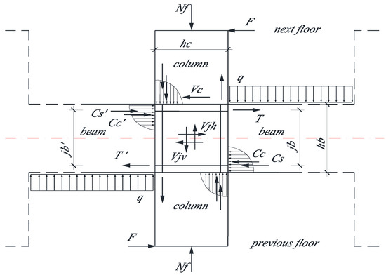
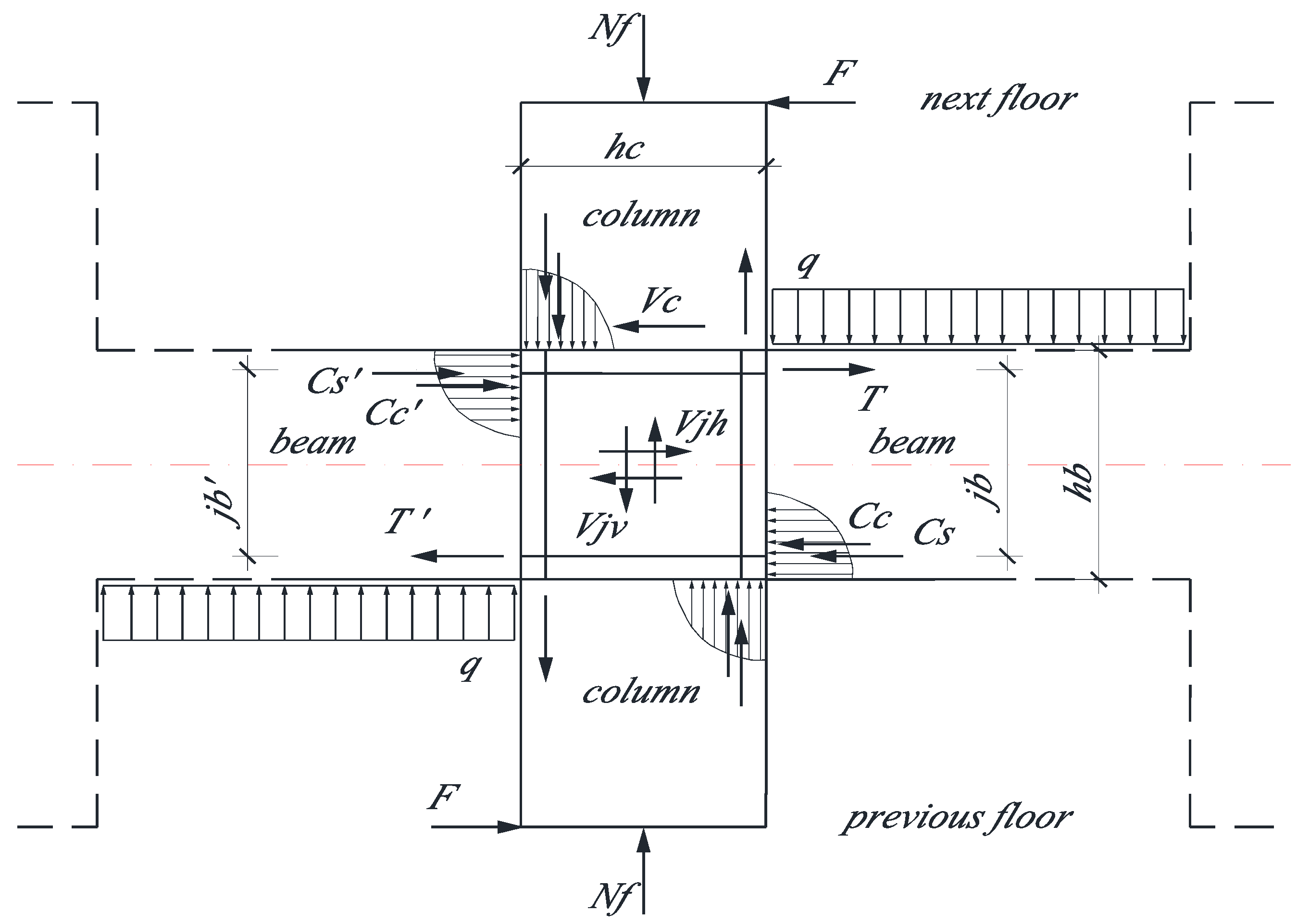
Hanson and Connor [1] defined the joint shear in an interior beam–column connection from Figure 1 as given in (1).
Figure 1.
Definition of joint shear force, transferred at the mid-height of a horizontal section (the red line), in interior RC beam–column connection.
The difficulty encountered in determining the forces from (1) leads to the adoption:
where and are moment at column face; and —the length of bending moment arm at the column face. It is assumed to be constant and unchanging in the process of deformation.
With the assumption of uniform distribution of the stresses along each face of the joint [9], the shear stresses in horizontal and vertical directions of the joint should equal each other and with sufficient accuracy we can write:
where and —the height of the beam and of the column, respectively.
In this article, the following tasks are set: 1. to compare the force values from Figure 1, at the face of the column and those from (2). 2. to compare the force values from Figure 1, at the bottom of the column, and those from (3).
The solution is made by considering the actual dimensions of the beams and columns in the mathematical model.
3. Method
3.1. Simple Beam-Support Reactions
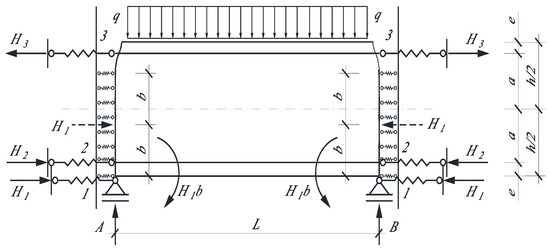
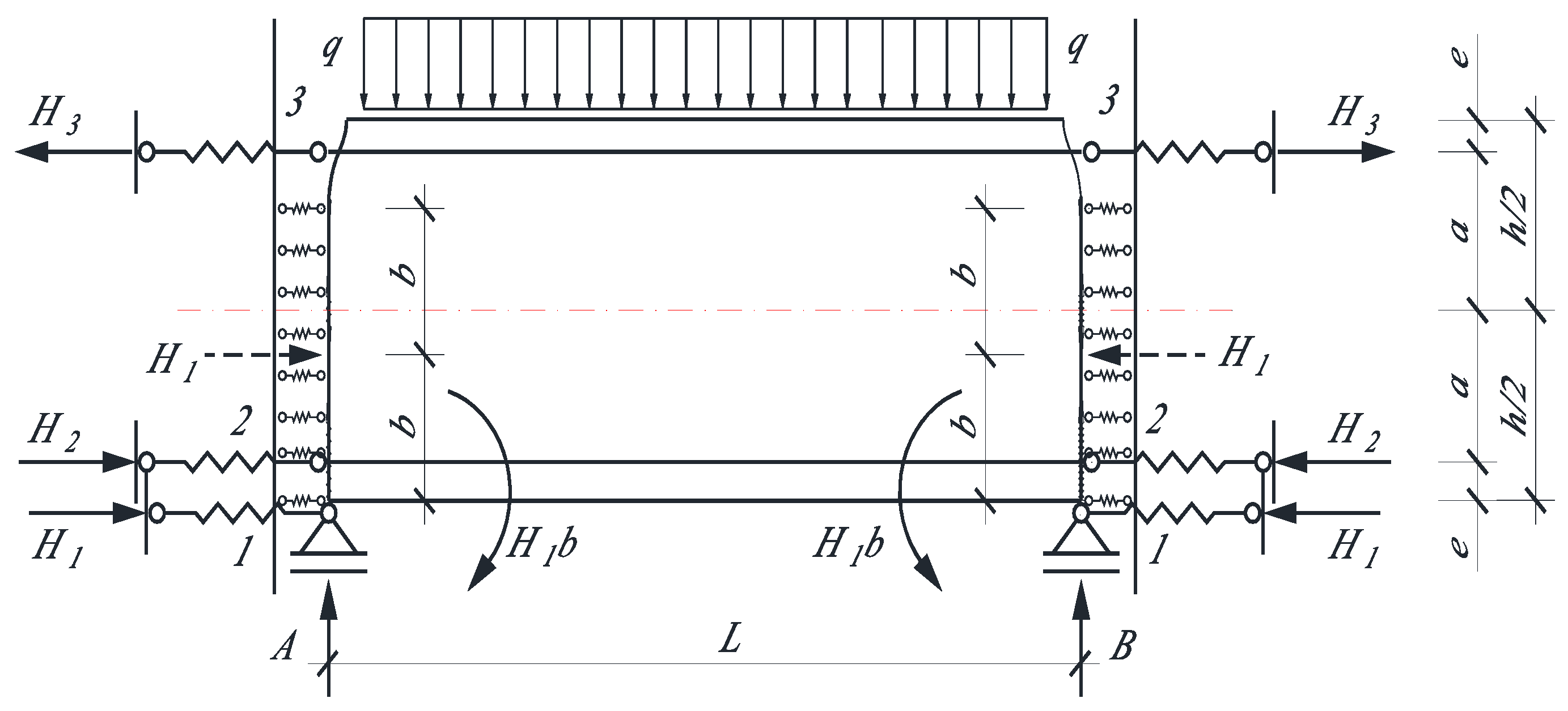
In [11], a beam from a frame structure is considered. The beam is statically indeterminate, prismatic, and symmetric. The beam is under the conditions of special bending with tension/compression and the Bernoulli–Euler hypothesis is considered (Figure 2). The solutions give the formulas of the horizontal support reactions below:
where ; ; —The coefficients of the linear springs.
Figure 2.
Supports of simple beams to columns—asymmetrical with respect to the axis of the beam (the red line).
—the modulus of elasticity of the concrete, of the reinforcement.
—the area of the cross-section of the concrete, and reinforcement.
The solution was performed in the symbolic environment of the MATLAB R2017b program [12].
3.2. Cantilever Beam-Support Reactions
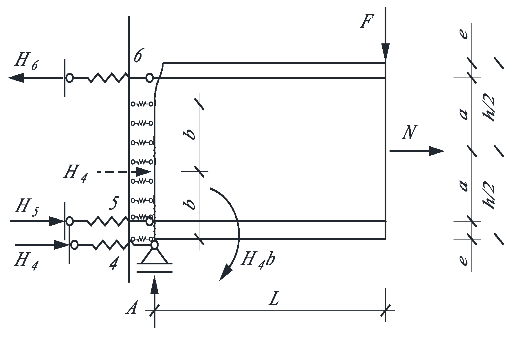
We will consider the columns coming out of the joint as a cantilever beam (Figure 3). All geometric and material characteristics introduced up to this point are preserved [13].
where the notations from (5) are used and also:
Figure 3.
Supports of the cantilever beam (column) to a joint—asymmetrical with respect to the axis of the beam (the red line).
4. Results and Discussion
For the numerical results, a beam and column with a cross-section of and was introduced. The transverse load is and . And more and , and . The distance varies in the interval and is monitored by the ratio . The length of the simple beam is and of the column is Two examples with a difference in the modulus of elasticity of concrete are considered. The modules used are for normal concrete and for high-strength concrete.
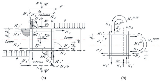
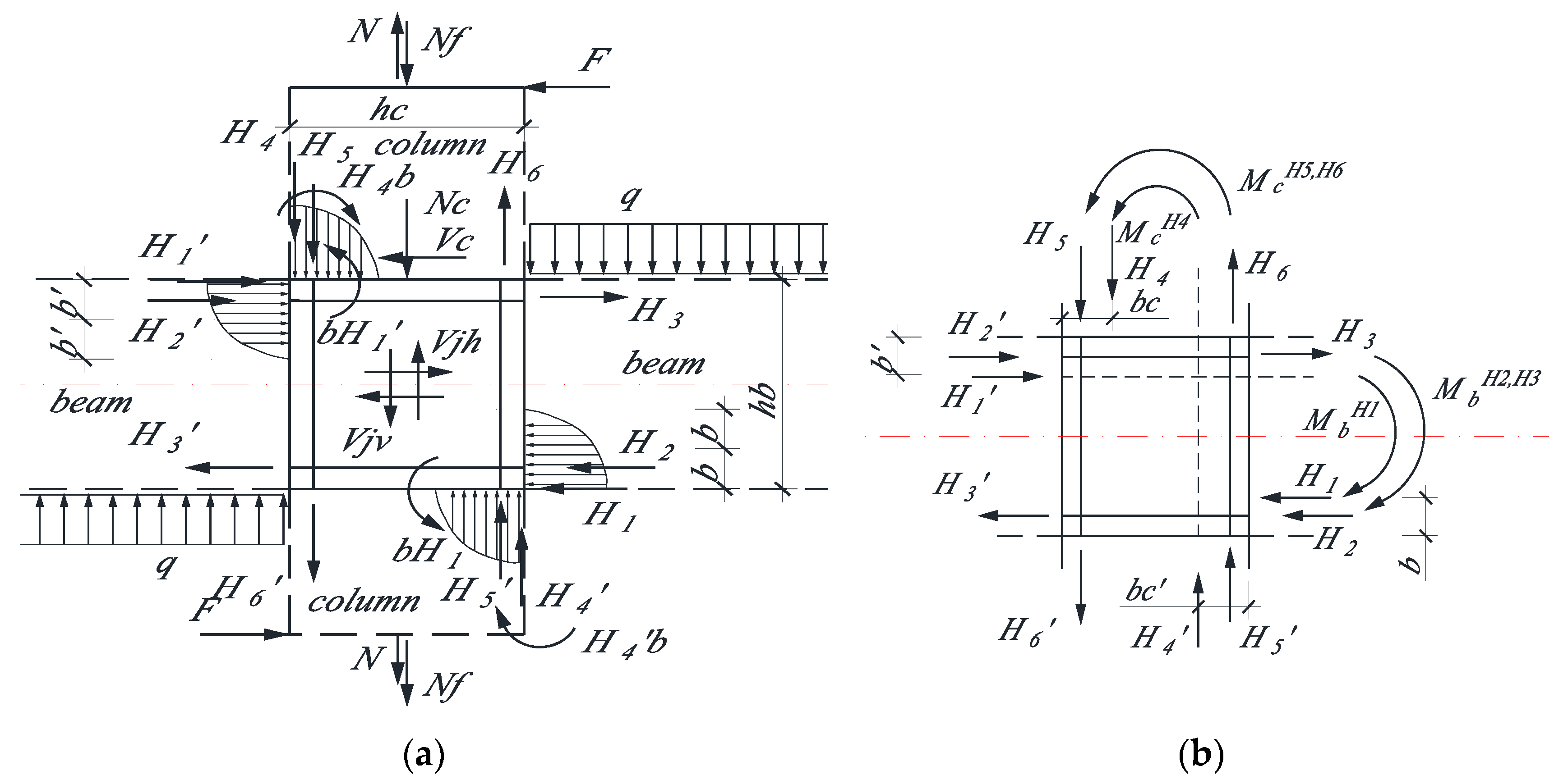
A new model for the determination of the shear force in RC interior beam–column connections is proposed (Figure 4a).
Figure 4.
The new definition of joint shear in interior RC beam–column connection. (a) distribution of forces; (b) moments of the forces in the concrete core of the joint. The red line is the axis of the beam.
If the frame is symmetric and other conditions are equal, we will have the equality of , and . Then (8) becomes:
4.1. Comparison of the Results of (2) and (9) (Figure 5)
The difference determined for the extreme values of (9) with these in (2) is respectively:
Figure 5.
Comparison of the results of (2) and (9)-simple beam. (a) the modulus of elasticity of the concrete is , 5.98% at , the certainty is in the direction of (9); (b) , 5.98% at , the certainty is in the direction of (2).
4.2. Comparison of the Results of (3) and Figure 4
From Figure 4 for the vertical force in the joint, we write:
From (3) and (2) it follows
Then what is proposed by the codes (11) [9] should be equal to what is obtained in (10), namely:
If , for the condition (12) to be fulfilled, the inequality must be fulfilled:
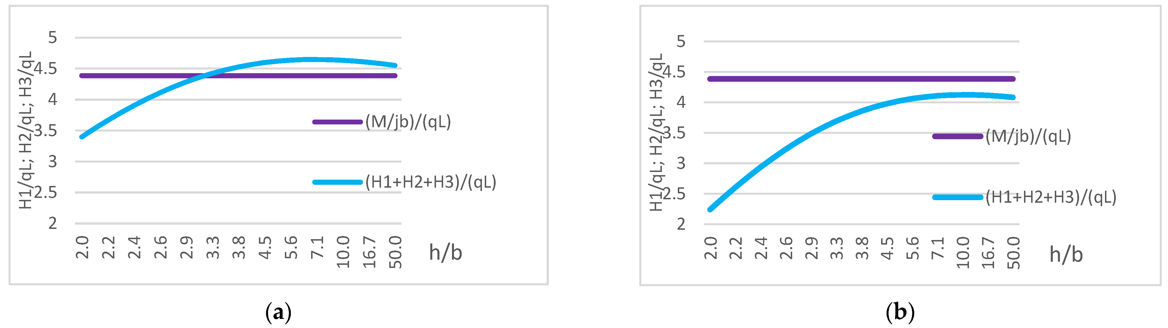
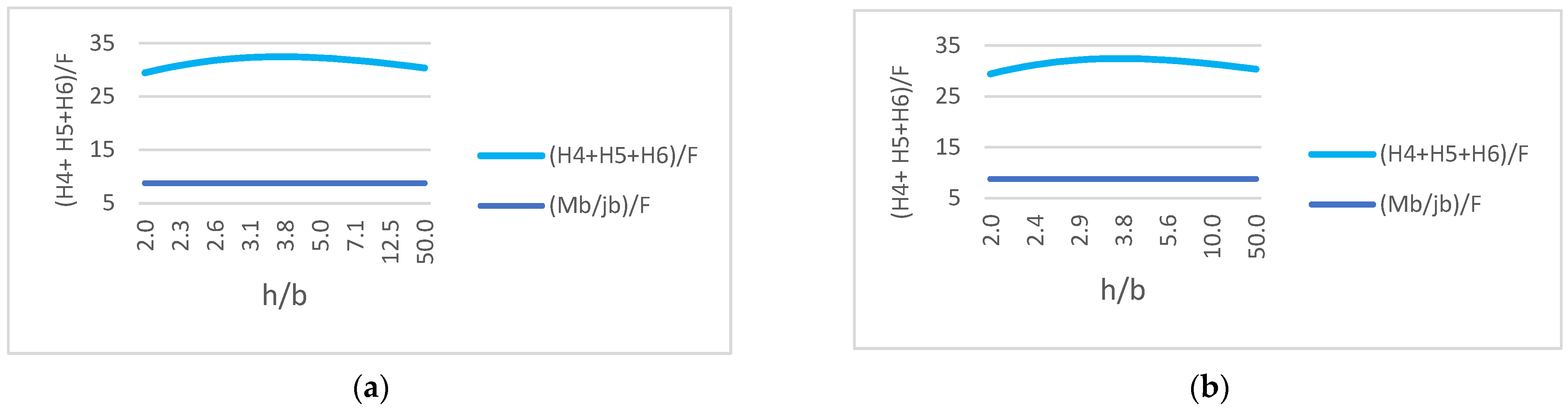
From Figure 6, it is obvious that the direction of the inequality is not satisfied.
Figure 6.
Comparison of the parameters of (13). (a) , 275% at ; (b) , 290% at .
Therefore, considering the real dimensions of the elements leads to forces occurring in the joint exceeding those recommended in the codes.
There is a serious underestimation of the contribution of the beam and of the column forces to the value of the joint shear force, from the expressions known in the literature. The new model shows that the contribution of the beam and the column forces is greater.
The distribution and direction of forces at the joint suggest that torsion (Figure 4b) is present. It would require additional reinforcement of the joint. This is a recommendation that we also find in [10] where it is proposed to increase the reinforcement in the joint without it passing to the beam. In [14], a model is shown in which a stainless-steel wire mesh is wrapped around the concrete core of the joint. The results show an almost 100% increase in deformation with the required amount of energy dissipation and maximum strength capacity.
Therefore, it can be expected that strengthening only the core of the joint with a stirrup would lead to an increase in its capacity without impairing the moment response of the frame.
5. Conclusions
Considering the real dimensions and material properties of the elements in a frame structure shows a redistribution of forces in the beams, columns, and joints. The derived expressions for the reactions of the horizontal supports give results that clearly show the distribution of forces along the height of the beam in the corresponding support. The obtained results for large deformations of elements show that force values exceeded those recommended in the design codes.
Funding
This research received no external funding.
Institutional Review Board Statement
This study is the independent development of the author.
Informed Consent Statement
Not applicable.
Data Availability Statement
The data presented in this study are available upon request from the corresponding author.
Conflicts of Interest
The author declares no conflict of interest.
References
- Hanson, N.W.; Connor, H.W. Seismic Resistance of Reinforced Concrete Beam-Column Joint. J. Struct. Div. 1967, 93, 533–560. [Google Scholar] [CrossRef] [Scilit]
- Park, R.; Keong, Y.S. Test on structural concrete beam-column joints with intermediate column bars. Bull. N. Z. Natl. Soc. Earthq. Eng. 1979, 12, 189–203. [Google Scholar] [CrossRef] [Scilit]
- Paulay, T. Equilibrium criteria for reinforced-concrete beam-column joints. ACI Struct J. 1989, 86, 635–643. [Google Scholar]
- Park, R. A Summary of Results of Simulated Seismic Load Tests on Reinforced Concrete Beam-Column Joints, Beams and Columns with Substandard Reinforcing Details. J. Earthq. Eng. 2002, 6, 147–174. [Google Scholar] [CrossRef] [Scilit]
- Shafaei, J.; Zareian, M.S.; Hosseini, A.; Marefat, M.S. Effects of joint flexibility on lateral response of reinforced concrete frames. Eng. Struct. 2014, 81, 412–413. [Google Scholar] [CrossRef] [Scilit]
- Ramaglia, G.; Lignola, G.P.; Fabbrocino, F.; Prota, A. Unified Simplified Capacity Model for Beam-Column Joints into RC Moment Resisting Frame. Appl. Sci. 2022, 12, 10709. [Google Scholar] [CrossRef] [Scilit]
- Guo, R.; Yang, D.; Jia, B.; Tang, D. Seismic Response of GFRP-RC Interior Beam-to-Column Joints under Cyclic Static Loads. Buildings 2022, 12, 1987. [Google Scholar] [CrossRef] [Scilit]
- Ahmad, N.; Rizwan, M.; Ilyas, B.; Hussain, S.; Khan, M.U.; Shakeel, H.; Ahmad, M.E. Nonlinear Modeling of RC Substandard Beam–Column Joints for Building Response Analysis in Support of Seismic Risk Assessment and Loss Estimation. Buildings 2022, 12, 1758. [Google Scholar] [CrossRef] [Scilit]
- Uma, S.R.; Jain, S.K. Seismic design of beam-column joints in RC moment resisting frames—Review of codes. Struct. Eng. Mech. 2006, 23, 579–597. [Google Scholar] [CrossRef] [Scilit]
- Shiohara, H. New model for shear failure of RC interior beam-column connection. J. Struct. Eng. 2001, 127, 152–160. [Google Scholar] [CrossRef] [Scilit]
- Doicheva, A. Off-center supported beam with additional elastic supports, located along the height of the beam and loaded with a distributed transverse load. In Proceedings of the XXIII International Scientific Conference VSU’2023, Sofia, Bulgaria, 22–24 June 2023; Volume I, pp. 451–460. (In Bulgarian) [Google Scholar]
- MATLAB R2017b; The MathWorks Inc.: Natick, MA, USA, 2017.
- Doicheva, A. Determination of the Shear Force in RC Interior Beam-Column Connections. Eurasia Proc. Sci. Technol. Eng. Math. 2023, 23, 361–371. [Google Scholar] [CrossRef] [Scilit]
- Faisal Hayat Khan, M.; Tahir, F.; Khan, Q.u.Z. Numerical simulation and performance evaluation of beam column joints containing frp bars and wire mesh arrangements. J. Mech. Contin. Math. Sci. 2021, 16, 112–130. [Google Scholar]
Disclaimer/Publisher’s Note: The statements, opinions and data contained in all publications are solely those of the individual author(s) and contributor(s) and not of MDPI and/or the editor(s). MDPI and/or the editor(s) disclaim responsibility for any injury to people or property resulting from any ideas, methods, instructions or products referred to in the content. |
© 2023 by the author. Licensee MDPI, Basel, Switzerland. This article is an open access article distributed under the terms and conditions of the Creative Commons Attribution (CC BY) license (https://creativecommons.org/licenses/by/4.0/).