


Abstract
This study proposes a new hybrid sensorless control estimation structure that provides a fault-tolerant control (FTC) when a position sensor fault occurs in a permanent magnet synchronous motor (PMSM). The proposed hybrid estimator combines two techniques using a speed-dependent weighting transition. High-frequency signal injection is applied at standstill and low speeds, while an extended Back-EMF observer takes over the position estimation at higher speeds. Within the transition band, the two estimators are combined by a vectorial cross-fade, resulting in a continuous position estimate. The sensor fault is detected by monitoring the angular difference between the sensor output and the complementary sensorless estimation output. The residual threshold is adjusted dynamically so that false triggers and missing triggers are avoided during acceleration and deceleration. Additionally, a decision-making delay is added to prevent noise-induced false alarms. When the fault is detected, the position feedback is smoothly switched to hybrid sensorless operation without interruption. The proposed strategy is tested across the full speed range of the PMSM via simulation, including steady-state, transient, and both fault-free and sensor fault scenarios. As a result of these scenarios, a new hybrid sensorless estimation structure capable of handling low-amplitude sensor biases in the position sensor across the full speed range is designed. Also, the Back-EMF estimation is compared with the extended Kalman filter at medium and high speeds, demonstrating a lower error detection threshold, quicker response, and reduced computational load.
1. Introduction
Interior permanent magnet synchronous motors (IPMSMs) are widely used in electric vehicle traction and industrial servo drives due to their high torque density and wide constant power region. Field-oriented control (FOC) of these machines requires continuous rotor position feedback, which is generally provided by a resolver or encoder. Sensor faults and failures such as complete loss of signal, intermittent loss or measurement error can disrupt the d-q decoupling and cause uncontrolled torque responses. Therefore, fault-tolerant control (FTC) strategies that detect faults and reconfigure the drive to sensorless operation are commonly used in safety-critical drive designs [1,2].
Sensorless position estimation methods depend on operating speed. At medium and high speeds, Back-Electromotive Force (Back-EMF)-based observers estimate the rotor angle from induced voltage. An extended Back-EMF model is used to design a simple disturbance observer for salient-pole permanent magnet synchronous motors (PMSMs) without model approximations [3]. However, these approaches fail at low and zero speeds because the Back-EMF magnitude becomes very small when the motor is near standstill. At these speeds, high-frequency (HF) signal injection techniques fill this gap by using magnetic saliency (Ld ≠ Lq) of the IPMSM [4]. A superimposed carrier voltage in high-frequency signal injection (HFSI) causes a position dependent current response and rotor angle is demodulated from this response. Pulsating injection offers higher accuracy and lower sensitivity to inverter dead-time effects than rotating injection [5]. Since neither technique alone covers full speed range, a transition mechanism is needed for continuous sensorless operation over the full speed range [6].
Two transition strategies have been reported in the literature: hysteresis-based hard switching and weighting-based soft transition. Hysteresis-based switching is computationally simple, but it causes torque and speed ripples at transition point, because two estimators produce different outputs at switching instant. On the other hand, the weighting-based transition eliminates these discontinuities by combining both estimates within speed band. This implementation reduces injection loop gain linearly to zero during the transition region [6]. In this paper, a vectorial cross-fade has been used based on sin/cos decomposition. This method also eliminates 2π wrapping effects that exist in direct angle combinations.
For fault detection, a commonly used approach in the literature monitors the deviation between the sensor angle and a sensorless estimation. The reconfiguration is triggered when this difference exceeds a threshold value [1]. A fixed threshold should be greater than worst case transient overshoot during acceleration and deceleration. This limitation causes slower detection and increases the duration of the current disturbance [7]. This trade-off is improved by adaptive threshold designs based on phase-locked loop (PLL) estimation dynamics and cumulative sum (CUSUM) algorithm [8]. However, current implementations do not cover standstill or low speeds because they mostly depend on Back-EMF estimates [9]. Statistical alternatives to geometric thresholding have also been explored, including sequential hypothesis testing [10], Mahalanobis-distance-based observation weighting [11], and residual-duration dual-parameter diagnosis for Kalman-filter-based position sensor fault detection [12].
This paper proposes a hybrid FTC architecture that performs fault detection across the entire speed range with dynamic threshold. The main contributions are as follows:
- A hybrid sensorless estimator that runs HF pulsating injection at standstill and low speeds and an extended Back-EMF disturbance observer at medium and high speeds in the background of the sensor based FOC. This estimator provides full speed range diagnostic.
- A vectorial weighted transition that combines two estimations within transition band by using sin/cos decomposition. This transition provides a smooth combined position information without wrapping.
- The residual signal is determined based on the difference between the position information from sensor and estimation from sensorless methods. Thanks to the on-delay and dynamic threshold, false alarms are prevented.
- A smooth reconfiguration is ensured, when a fault is detected. Estimation methods always run in the background for this bumpless reconfiguration.
The proposed strategy is validated on a MATLAB/Simulink (version R2023a; The MathWorks Inc., Natick, MA, USA) model of an IPMSM drive. The remainder of this paper is organized as follows. Section 2 presents the IPMSM model. Section 3 explains the hybrid estimation and transition algorithm. Section 4 describes the fault detection and reconfiguration logic. Section 5 presents the simulation results, and Section 6 concludes the paper.
2. Mathematical Model of the IPMSM
The IPMSM model used throughout this work is formulated in the rotor reference frame and then transformed into the estimated synchronous frame to support the Back-EMF observer. The model has been limited to the fundamental electrical behaviour relevant to position estimation and fault detection, cogging torque, iron losses, and magnetic saturation have been neglected.
2.1. Voltage Equations in the Rotor Reference Frame
Applying the Park transformation to three phase stator voltage equations yields the IPMSM model in rotor aligned d-q frame
where vd, vq and id, iq are the d- and q-axis stator voltages and currents, Rs is the stator resistance, Ld and Lq are the d- and q-axis inductances, ψm is the permanent magnet flux linkage, and ωe = p ωm is the electrical angular velocity, with p the number of pole pairs and ωm the mechanical angular velocity. For an IPMSM the inductances satisfy Lq > Ld, this magnetic saliency has been used on HF injection method introduced in Section 3.1.
2.2. Extended Back-EMF Formulation
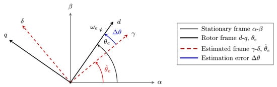
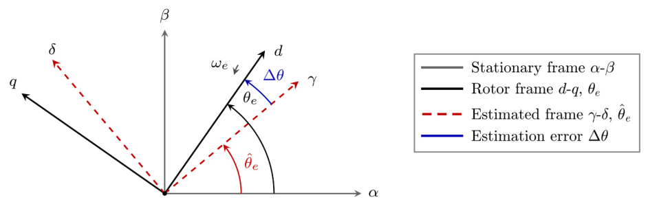
The model (1) cannot be applied directly in a sensorless drive because the d-q frame is defined by the unknown rotor angle θe. The geometric relations between relevant reference frames have been summarized in Figure 1. Transforming (1) into the estimated synchronous frame γ-δ, whose orientation differs from d-q by the estimation error , does not by itself resolve the difficulty. When Ld ≠ Lq, the rotor frame inductance matrix diag(Ld,Lq) is not invariant under this change of basis, and the transformed model contains non-diagonal terms that directly depend on Δθ.
Figure 1.
Reference frames: stationary α-β, rotating d-q and estimated γ-δ.
The extended Back-EMF formulation [3,13] eliminates this coupling by an algebraic rearrangement of (1). That absorbs all saliency-related effects into a single q-axis voltage source while providing inductance matrix free of speed-dependent terms. After performing the required substitutions and simplification, the IPMSM model takes the compact matrix form
where s≜d/dt and the extended Back-EMF is defined as
Two properties of (2) underpin the observer design. The inductance appears in impedance matrix as sLd, that is independent of speed. Also, all rotor position information has been included in the single voltage vector aligned with q-axis. Because of these two features, Equation (2) keeps the same form in any synchronous frame. Sensorless estimation therefore reduces to finding the direction of this voltage vector.
Expression (3) also exposes the principal limitation of Back-EMF. Since each term in Eex is proportional to ωe or diq/dt, the rotor angle becomes unobservable during steady-state operation at standstill because the signal vanishes.
To express the model in the estimated frame, the rotation matrix
is applied to the voltage and current vectors of (2) to perform the change of reference frame from d-q to γ-δ. Because the impedance matrix is independent of speed, it does not change form in the estimated frame and only the Eex vector is rotated. Evaluating yields the scalar projections
For small estimation errors sin(Δθ) ≈ Δθ, so eγ behaves like linear function of the angular error with slope −Eex close to Δθ ≈ 0. The Back-EMF observer described in Section 3.2 exploits this property by driving eγ to zero through a PLL, when has converged to θe.
2.3. Mechanical Dynamics and Electromagnetic Torque
The electromagnetic torque of the IPMSM combines magnet alignment term and a reluctance term caused by saliency
The first term in (6) is conventional magnet torque, while the second is the reluctance torque exploited under maximum torque per ampere operation. The mechanical subsystem is defined by Newton’s equation
together with the kinematic relation dθm/dt = ωm, where J is rotor moment of inertia, B is viscous friction coefficient, and TL is external load torque. The electrical position and speed are related to the mechanical quantities through θe = p θm and ωe = p ωm.
3. Hybrid Sensorless Position Estimation
3.1. High-Frequency Pulsating Signal Injection at Zero and Low Speeds
Since Eex becomes zero near standstill, the HF pulsating signal injection method [4,5] is combined in this structure to restore position observability. It superimposes a high-frequency carrier voltage on the estimated d-axis of the controller and extracts rotor position from the carrier frequency current response, which is modulated by the magnetic saliency Ld ≠ Lq of the IPMSM.
A pulsating carrier is added to the estimated d-axis voltage reference at angular frequency ωh well above current loop bandwidth. Because the injection is defined in the γ-δ frame, its projection onto actual rotor frame is obtained through R⊤(Δθ), giving
Although pulsating carrier signal is only injected on the estimated d-axis, when Δθ ≠ 0 the same physical voltage vector projects onto both axes through cosΔθ and −sinΔθ. This q-axis projection, that becomes zero with perfect alignment, makes estimation error observable thanks to saliency Ld ≠ Lq.
At ωh, the resistive and rotational terms in (1) are negligible when compared with inductive impedances jωhLd and jωhLq. Therefore, rotor carrier currents follow from term-by-term integration
Transforming (9) back to estimated frame with R(Δθ) and applying the identity sinΔθ cosΔθ = 1/2sin(2Δθ), the carrier frequency component of the current on the estimated q-axis is
which carries the estimation error with saliency dependent term (Lq − Ld)/(LdLq). Critically, (10) is independent of ωe, so the response continues at standstill.
The position information is extracted from (10) in three steps. A second order bandpass filter centred at ωh with bandwidth Bw
isolates the carrier frequency component of iq from fundamental drive currents. Multiplying bandpass output by the synchronization signal sin(ωht) and applying sin2(ωht) = 1/2[1 − cos(2ωht)] yields
in which the position information is shifted to baseband, while the modulation simultaneously generates a high-frequency image at 2ωh. A first-order low-pass filter (LPF) with cutoff ωLP ≪ 2ωh,
suppresses the high-frequency image, leaving baseband error signal
where the demodulation gain is
εhf = Khfsin(2Δθ) ≈ 2Khf Δθ,
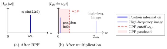
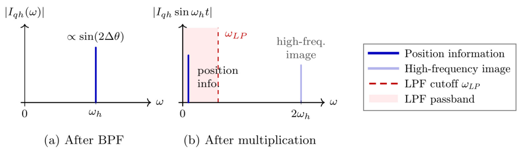
The error signal εhf behaves like linear function of the angular error while Δθ ≈ 0. The progression of the position-bearing content through this chain is shown in Figure 2. After the bandpass filter, position information is centralized at ωh with amplitude proportional to sin(2Δθ). Then as a result of multiplication operation, position information carrier signal and high-frequency image at 2ωh are formed. Lastly, this high-frequency image signal is filtered with LPF to obtain only position information signal, and the error signal is derived from the remaining component. The distinctive feature of pulsating injection is that position information appears as amplitude of carrier signal and is recovered after demodulation. In rotating signal injection, by contrast, the position information appears at phase of carrier signal rather than amplitude, requiring a different demodulation structure.
Figure 2.
Pulsating injection demodulation: (a) bandpass output and (b) multiplication by sin(ωht).
A type-2 PLL is used to get εhf, a proportional–integral (PI) controller in this PLL drives it to zero and output of controller yields the speed estimate . Then that speed is also integrated to obtain the angle estimate . In order to clearly separate the angle dynamics from carrier residuals, the PI bandwidth is set well below ωLP.
The reliability of the injection-based estimator degrades at higher speeds because inverter dead-time and switching effects attenuate the carrier signal. Furthermore, as speed increases, the fundamental current frequency approaches to injection frequency, degrading signal quality and demodulation. These effects set an upper bound on the speed at which the HF estimate is reliable.
3.2. Extended Back-EMF Observer at Medium and High Speeds
In this section, Back-EMF observer operates directly on the rotor frame (2) in Section 2.2. It reconstructs the extended Back-EMF components on estimated γ-δ axes and calculates θe from their orientation.
Rearranging (2) for current dynamic and applying same transformation to obtain (5) yields the voltage equations in estimated frame
where is the speed estimation that produced by observer and (vγ,vδ) and (iγ,iδ) are measurable quantities from sensors. Solving (16) for extended Back-EMF components gives
Direct implementation of (17) is not practical because pure differentiator s amplifies measurement noise on currents. Two filtering stages are necessary in there. Firstly, low-pass filter is applied on each component
where ωc is chosen well above the fundamental but below the switching harmonics. That limits band of di/dt. Secondly, to suppress the slow drift and DC bias that accumulate in (17), a high-pass filter (HPF) with the same cutoff is applied on each component
The combined LPF and HPF structure keeps speed proportional term of Eex as original, while rejecting current noise and steady-state offsets.
Once and have been calculated, the estimation error is determined from their orientation with arctangent expression
that takes advantage of projection structure of (5). When Δθ is small, the arctangent reduces to the linear approximation Δθ ≈ −eγ/Eex used in Section 2.2. However, (20) preserves the correct sign and range over the full [−π,π] interval. That is critical during transients where Δθ may briefly exceed the small angle range.
As in Section 3.1, a type-2 PLL is used to get εbemf. PI controller in this PLL drives it to zero and output of controller yields the speed estimate . To reduce ripple and switching noise on , a first-order filter is applied to the angle output with cutoff ωpf,
As ωe decreases, the signal-to-noise ratio of (17) changes because and become smaller while measurement and quantization noise remain the same. Below the threshold mechanical speed, arctangent expression in (20) begins to lose its accuracy. Therefore, observer is enabled only above this speed threshold.
3.3. Weighted Transition Between Estimation Methods
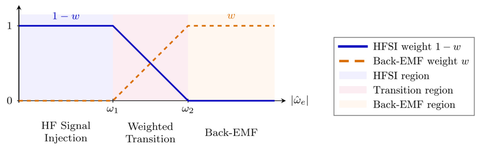
The HFSI and Back-EMF estimations only cover their operating range, so a continuous transition between methods is required for full speed range operation. The approach applies linear speed-dependent weight with vectorial combination of the two angle estimations.
Let ω1 < ω2 bound transition band in electrical speed. The weighting coefficient is defined as
so that w = 0 selects HFSI estimation, w = 1 selects the Back-EMF estimation, and intermediate values produce combined estimation according to weighting coefficient.
A direct combination of the two angle outputs is unsuitable because of 2π wrapping. Two estimations can differ by approximately 2π even when both are accurate. Also, when the speed exits the transition region, angle estimation would cause jump on estimation. Therefore, angle combination is performed with Cosine–Sine decomposition,
from which the composite angle is recovered as
Interpolation is performed on unit circle instead of unwrapped angle. As a result, continuity across 2π is ensured and angle jumps are avoided.
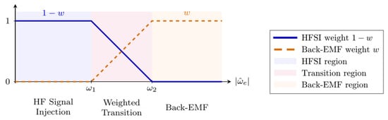
Applied low-pass filter and rate limiter further smooth the transition. That filter applied to suppresses high-frequency speed changes to prevent chattering near region limits. Also, rate limiter limits slew rate during abrupt speed transients. The resulting weighting profile and operating regimes are summarized in Figure 3.
Figure 3.
Speed-dependent weighting profile of the hybrid sensorless estimator.
4. Fault Detection and Control Reconfiguration
The fault detection and isolation (FDI) layer runs in parallel with the sensored FOC to generate fault flag. The hybrid estimator in (Section 3) operates continuously in the background, so residual is available across the full speed range including standstill.
4.1. Residual Generation
The residual is angular difference between encoder angle θenc and sensorless estimation from (24). Direct subtraction is discontinuous at 2π boundary, so shortest path form
maps the result into (−π, π] and prevents 2π wrapping issue. A washout high-pass filter removes accumulated bias between two estimations during normal operation.
4.2. Adaptive Threshold with Dynamic Scaling
A fixed threshold must exceed the worst-case transient excursion of r during speed ramps, which delays detection of low-amplitude faults [7]. The threshold is therefore formed as
δth = [(1 − w)δhf + wδbe] + kdyn|iq|
The bracketed term is the base threshold, which is not constant but is calculated according to the same speed-dependent weight coefficient described in Section 3. Here, δhf and δbe are the constant threshold values associated with the HFSI and Back-EMF methods. The base threshold is interpolated between them so that each method has its own threshold. The dynamic term kdyn then scales the total threshold with the q-axis current. During acceleration, large |iq| increases total threshold and suppresses false alarms. At steady state it becomes close to base threshold and sharpens sensitivity. An asymmetric rate limiter extends the decay tail so the threshold does not fade faster than the transient it tracks [8].
4.3. Fault Confirmation and Seamless Reconfiguration
When |r| ≥ δth, an on-delay timer requires fault to persist for Tconf continuously before raising fault flag. Thus, it detects fast position jumps by rejecting noise-induced faults [14]. Upon confirmation, SR latch sets the permanent fault flag F with no reset path. Reconfiguration is irreversible to avoid mode oscillation due to intermittent sensor faults [1]. The complete signal flow, from residual generation to reconfiguration, is shown in Figure 4: when the flag F is set, sensor feedback θenc is switched with hybrid sensorless estimation , reducing reconfiguration to a single position source selection. Since the estimator has been running in the background during sensored operation, has already converged to θenc, so no transient torque is observed during transition [15].
Figure 4.
Signal flow diagram of the FDI and control reconfiguration; fault flag F switches angle.
5. Simulation Results and Discussion
5.1. Simulation Platform
The motor speed reference follows step ramp profile from standstill to the maximum operating speed. This speed reference is designed to pass through the HFSI-dominant region, the transition band, and the Back-EMF-dominant region. One fault-free scenario and three fault scenarios are evaluated. Fault injection is a step angle offset applied to encoder output at specified time step. The simulation platform and system parameters are listed in Table 1.
Table 1.
Simulation platform and system parameters.
5.2. Steady-State Estimation Accuracy
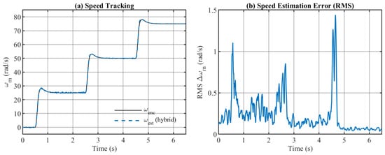
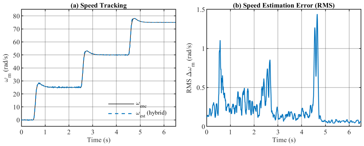
Figure 5 shows hybrid estimator speed output ωest tracking encoder speed ωenc in the fault-free scenario, together with estimation error Δωm between sensor speed information and speed estimation. The hybrid output follows the reference at all three steady-state speeds with the remaining error within a narrow band. This confirms that the vectorial combination introduces no bias at any operating point.
Figure 5.
Fault-free scenario. (a) Encoder speed ωenc and hybrid estimate ωest over full speed range. (b) Estimation error Δωm.
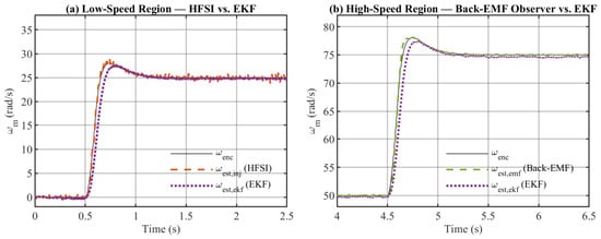
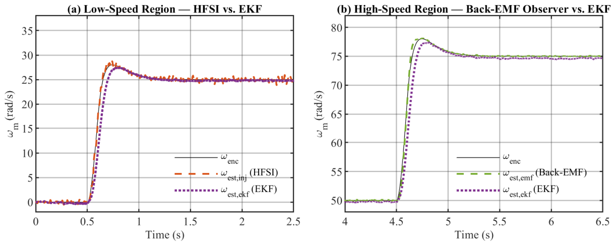
Figure 6 zooms into the HFSI-dominant low-speed region and the Back-EMF-dominant high-speed region, comparing each estimation method against the extended Kalman filter (EKF) benchmark [16]. The saliency-based estimation ωest,inj closely follows ωenc at low speed, while the Back-EMF estimation ωest,emf converges to the encoder reference at high speed. At low speed, EKF produces larger transient deviations, because Back-EMF amplitude decreases as electrical angular velocity approaches zero, reducing observability. At high speed, both methods converge to the reference but filter group delay and saliency mismatch in EKF model cause slight steady-state bias in EKF estimation. These findings confirm that neither a single Back-EMF observer nor an EKF covers both regimes, motivating the hybrid architecture.
Figure 6.
EKF benchmark comparison. (a) Low-speed region: HFSI estimate ωest,inj vs. EKF estimate ωest,ekf. (b) High-speed region: Back-EMF estimate ωest,emf vs. EKF estimate ωest,ekf.
5.3. Transient Performance During Speed Ramp
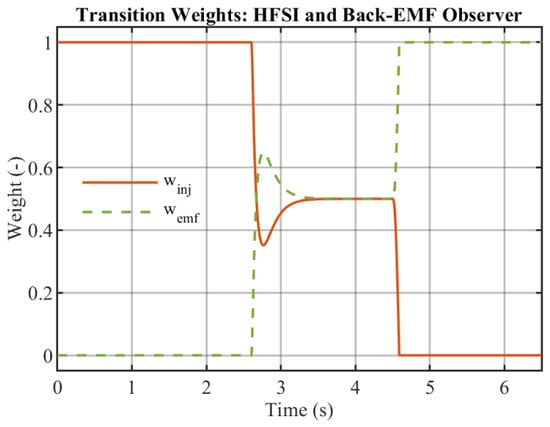
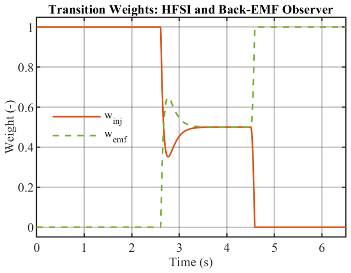
Figure 7 shows the evolution of the weighting factor winj and wemf during the ramp scenario. Below the transition band winj = 1 and wemf = 0, so the HFSI estimation is dominant. As the speed information enters the transition region, both weighting factors vary continuously, and the vectorial cross-fade interpolates between two estimations. Above the upper boundary winj = 0 and wemf = 1, transferring full authority to Back-EMF estimation.
Figure 7.
Weighting factor evolution during the speed ramp.
5.4. Fault Detection and Reconfiguration Response
Three fault scenarios inject a 0.5 rad step angle offset into the encoder output at different time steps, covering all three estimation regimes. In every case, the injected offset exceeds the base threshold for long enough to activate confirmation timer Tconf.
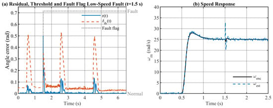
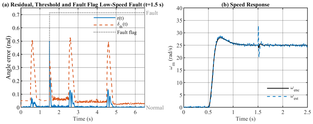
Scenario 1 (Figure 8) injects a fault at low speed, where HFSI estimation is dominant. The residual r(t) exceeds the adaptive threshold δth immediately and remains above it for the full confirmation interval, setting the fault flag F. The speed response shows a brief transient as the controller switches to sensorless operation, with steady-state tracking recovered within one settling period.
Figure 8.
Scenario 1: fault injected at low speed (HFSI dominant). (a) Residual r(t), adaptive threshold δth and fault flag F. (b) Speed response.
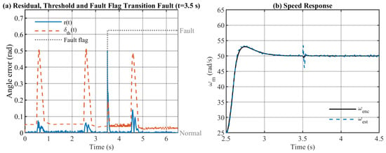
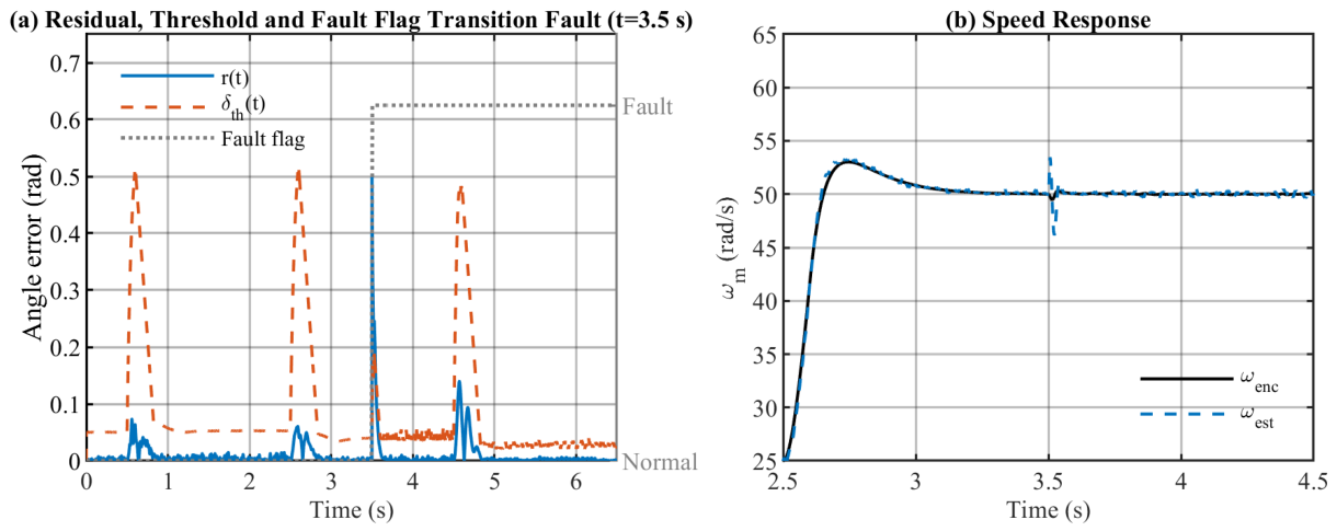
Scenario 2 (Figure 9) injects a fault in the transition region, where both estimators contribute to the combined output. The base threshold is interpolated between HFSI and Back-EMF base threshold values. The residual still exceeds the threshold cleanly, the fault flag is set within one confirmation interval, and reconfiguration speed transient is of comparable magnitude to Scenario 1.
Figure 9.
Scenario 2: fault injected in the transition region. (a) Residual r(t), adaptive threshold δth and fault flag F. (b) Speed response.
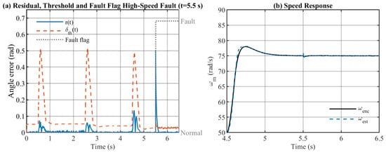
Scenario 3 (Figure 10) injects a fault at high speed, where Back-EMF estimation is in full control. The residual clearly exceeds the adaptive threshold, the fault flag is set, and the drive continues at the same speed reference using the Back-EMF estimation, with only a minor transient response. Across all three scenarios, FDI layer produces no false alarms and achieves detection within expected confirmation time.
Figure 10.
Scenario 3: fault injected at high speed (Back-EMF dominant). (a) Residual r(t), adaptive threshold δth and fault flag F. (b) Speed response.
6. Conclusions
A position sensor fault-tolerant control architecture for IPMSM drives was developed by combining high-frequency signal injection at standstill and low speeds with an extended Back-EMF observer at medium and high speeds. These methods are combined with a vectorial weighted transition that produces a continuous rotor angle across the full speed range. A fault detection and isolation layer monitors the residual from the difference between the encoder angle and the hybrid estimation. This triggers an irreversible reconfiguration to sensorless operation with a dynamically scaled threshold and a confirmation delay at the moment of detection. Across fault scenarios, including the HFSI-dominant, transition, and Back-EMF-dominant regimes, the residual cleanly exceeds the adaptive threshold with no false alarms during speed transients and tracking recovers after reconfiguration. A comparison with the extended Kalman filter, which loses Back-EMF observability near standstill and retains a small steady-state bias at high speed, supports necessity of the hybrid structure rather than a single estimation method. Future work will focus on extending structure to multiple parallel sensor faults and performing experimental validation on a hardware test bench.
Author Contributions
Conceptualization, B.S. and F.C.; methodology, B.S.; software, B.S.; validation, B.S.; formal analysis, B.S.; investigation, B.S.; writing—original draft preparation, B.S.; writing—review and editing, B.S. and F.C.; visualization, B.S.; supervision, F.C.; project administration, F.C. All authors have read and agreed to the published version of the manuscript.
Funding
This research received no external funding.
Institutional Review Board Statement
Not applicable
Informed Consent Statement
Not applicable
Data Availability Statement
The original contributions presented in this study are included in the article. Further inquiries can be directed to the corresponding author.
Conflicts of Interest
The authors declare no conflicts of interest.
Abbreviations
The following abbreviations are used in this manuscript:
| Back-EMF | Back-Electromotive Force |
| CUSUM | Cumulative Sum |
| EKF | Extended Kalman Filter |
| FDI | Fault Detection and Isolation |
| FOC | Field-Oriented Control |
| FTC | Fault-Tolerant Control |
| HF | High-Frequency |
| HFSI | High-Frequency Signal Injection |
| HPF | High-Pass Filter |
| IPMSM | Interior Permanent Magnet Synchronous Motor |
| LPF | Low-Pass Filter |
| PI | Proportional–Integral |
| PLL | Phase-Locked Loop |
| PMSM | Permanent Magnet Synchronous Motor |
References
- Jeong, Y.-S.; Sul, S.-K.; Schulz, S.E.; Patel, N.R. Fault detection and fault-tolerant control of interior permanent-magnet motor drive system for electric vehicle. IEEE Trans. Ind. Appl. 2005, 41, 46–51. [Google Scholar] [CrossRef] [Scilit]
- Meinguet, F.; Kestelyn, X.; Semail, E.; Gyselinck, J. Fault detection, isolation and control reconfiguration of three-phase PMSM drives. In Proceedings of the IEEE International Symposium on Industrial Electronics (ISIE) 2011, Gdańsk, Poland, 27–30 June 2011; pp. 2091–2096. [Google Scholar]
- Morimoto, S.; Kawamoto, K.; Sanada, M.; Takeda, Y. Sensorless control strategy for salient-pole PMSM based on extended EMF in rotating reference frame. IEEE Trans. Ind. Appl. 2002, 38, 1054–1061. [Google Scholar] [CrossRef] [Scilit]
- Liu, J.M.; Zhu, Z.Q. Novel sensorless control strategy with injection of high-frequency pulsating carrier signal into stationary reference frame. IEEE Trans. Ind. Appl. 2014, 50, 2574–2583. [Google Scholar] [CrossRef] [Scilit]
- Luo, X.; Tang, Q.; Shen, A.; Zhang, Q. PMSM sensorless control by injecting HF pulsating carrier signal into estimated fixed-frequency rotating reference frame. IEEE Trans. Ind. Electron. 2016, 63, 2294–2303. [Google Scholar] [CrossRef] [Scilit]
- Wu, X.; Wu, T.; Huang, S.; Pan, W.; Lyu, M.; He, Y.; Cui, H. Hybrid position estimation strategy with a smooth transition for IPMSM sensorless drives in the wide speed range. IEEE Trans. Power Electron. 2022, 37, 7916–7930. [Google Scholar] [CrossRef] [Scilit]
- Lee, D.; Akatsu, K. An improved position sensor fault detection and algorithm transition using adaptive threshold for sensorless control of IPMSM. In Proceedings of the IEEE Energy Conversion Congress and Exposition (ECCE) 2019, Baltimore, MD, USA, 29 September–3 October 2019; pp. 910–915. [Google Scholar]
- Lee, D.; Akatsu, K. The study on sensor fault detection and algorithm transition using adaptive threshold in position self-sensing control for IPMSM. IEEE Trans. Ind. Electron. 2021, 68, 10459–10469. [Google Scholar] [CrossRef] [Scilit]
- Taege, S.; Schiefhauer, H.; Ali, A.; Müller, B.; Janek, G. Simple fault-tolerant control of a permanent magnet synchronous motor with faulty position sensor. In Proceedings of the IEEE International Electric Machines and Drives Conference (IEMDC) 2023, San Francisco, CA, USA, 15–18 May 2023; pp. 1–10. [Google Scholar]
- Gao, G.; Zhong, Y.; Gao, S.; Gao, B. Double-Channel Sequential Probability Ratio Test for Failure Detection in Multisensor Integrated Systems. IEEE Trans. Instrum. Meas. 2021, 70, 3514814. [Google Scholar] [CrossRef] [Scilit]
- Gao, B.; Hu, G.; Zhu, X.; Zhong, Y. A Robust Cubature Kalman Filter with Abnormal Observations Identification Using the Mahalanobis Distance Criterion for Vehicular INS/GNSS Integration. Sensors 2019, 19, 5149. [Google Scholar] [CrossRef] [Scilit] [PubMed]
- Chen, J.; Wang, B.; Li, S.; Cheng, Y.; Chen, J.; Dong, H. Fault Diagnosis and Fault-Tolerant Control of Permanent Magnet Synchronous Motor Position Sensors Based on the Cubature Kalman Filter. Sensors 2025, 25, 6030. [Google Scholar] [CrossRef] [Scilit] [PubMed]
- Ichikawa, S.; Chen, Z.; Tomita, M.; Doki, S.; Okuma, S. Sensorless control of an interior permanent magnet synchronous motor on the rotating coordinate using an extended electromotive force. In Proceedings of the 27th Annual Conference of the IEEE Industrial Electronics Society (IECON) 2001, Denver, CO, USA, 29 November–2 December 2001; pp. 1667–1672. [Google Scholar]
- Lee, D.; Akatsu, K. The study on position sensor fault detection and algorithm transition from sensored to sensorless control for IPMSM. In Proceedings of the IEEE 12th International Conference on Power Electronics and Drive Systems (PEDS) 2017, Honolulu, HI, USA, 12–15 December 2017; pp. 728–733. [Google Scholar]
- Lee, T.; Lee, H.; Jang, P.; Hwang, Y.; Nam, K. Position fault detection for UAM motor with seamless transition. IEEE Access 2021, 9, 168042–168054. [Google Scholar] [CrossRef] [Scilit]
- Mwasilu, F.; Jung, J.-W. Enhanced fault-tolerant control of interior PMSMs based on an adaptive EKF for EV traction applications. IEEE Trans. Power Electron. 2016, 31, 5746–5758. [Google Scholar] [CrossRef] [Scilit]



Disclaimer/Publisher’s Note: The statements, opinions and data contained in all publications are solely those of the individual author(s) and contributor(s) and not of MDPI and/or the editor(s). MDPI and/or the editor(s) disclaim responsibility for any injury to people or property resulting from any ideas, methods, instructions or products referred to in the content. |
© 2026 by the authors. Licensee MDPI, Basel, Switzerland. This article is an open access article distributed under the terms and conditions of the Creative Commons Attribution (CC BY) license.