


Abstract
This paper proposes and evaluates an innovative strengthening technique for seismically damaged hybrid steel–concrete shear walls with centered openings. The proposed method involves strengthening of the damaged reinforced concrete coupling beams by installing additional steel plates anchored to the piers of the shear walls. To investigate the effectiveness of this solution, a hybrid steel–concrete shear wall specimen was constructed at 1:3 reduced scale and subjected initially to cyclic lateral loading, prior to failure, aiming to study the seismic performance of the wall. The specimen comprises a reinforced concrete web panel with I-shaped steel profiles partially embedded in the edges and features vertically aligned rectangular door openings. Subsequently, advanced numerical analysis was performed to analyses the efficiency of the proposed strengthening approach. Based on the numerical results obtained, it can be concluded that the proposed strengthening solution can successfully restore and enhance the load-bearing capacity of the hybrid shear wall following a seismic event.
1. Introduction
Hybrid steel–concrete structural walls represent an efficient solution for high-rise buildings located in seismic areas and are frequently used in applications where architecture and design call for slender, large spans and wide spaces. The embedment of structural steel profiles within the reinforced concrete piers combines the ductility and energy-dissipation capacity of steel with the stiffness and compressive strength of concrete. When openings are required, the wall piers are connected by coupling beams and the system responds as a coupled wall, achieving considerably higher lateral stiffness and overturning resistance than the isolated piers would. As a result of the coupled response of the piers, the coupling beams are subjected to large shear forces and bending moments.
Experimental investigations on steel–concrete composite walls with openings and plate-reinforced coupling beams [1] indicate that steel plates acting compositely with the reinforced concrete member substantially increase its shear strength, stiffness and ductility. Of relevance for post-earthquake interventions, externally attached steel plates connected by bolts passing through the wall thickness proved to be an effective strengthening technique for reinforced concrete coupling beams with small span-to-depth ratios [2,3]. Despite these advantages, the strengthening of hybrid steel–concrete walls remain insufficiently covered by the current design codes, with limited guidance provided in codes. In current practice, the retrofitting of reinforced concrete coupling beams is commonly performed using steel plates placed on one or both faces of the member, a technique that is easy to apply and does not modify the architectural configuration of the wall. The present paper proposes and numerically evaluates a strengthening approach applied to a hybrid steel–concrete shear wall specimen called CSRCW-21-CO, whose reinforced concrete coupling beams failed in shear during the cyclic test, as described later in Section 4. The strengthened specimen, denoted CSRCW-21-CO-SSP (Strengthening with Steel Plates), incorporates steel plates installed on both faces of the damaged coupling beams and anchored to the wall piers. The objectives of the study are to present the strengthening concept of the wall and to assess, by means of nonlinear finite-element analysis, the ability of the proposed solution to restore or even enhance the load-bearing capacity of the damaged hybrid shear wall with centered openings.
2. Research Program
The present study is part of a research program developed at Politehnica University Timișoara, within the Faculty of Civil Engineering—Department of Civil Engineering and Building Services. The main objective of this program is to investigate the seismic performance of hybrid steel–concrete shear walls with various structural configurations [4,5,6,7]. This research aims also to evaluate and develop innovative solutions for strengthening such hybrid structural walls damaged during seismic events [8]. Therefore, the strengthening solution presented in the following sections refers to a specimen (CSRCW-21-CO) previously tested prior to failure as part of the research program and used as the reference specimen for the present study.
2.1. Structural Configuration of the Specimen Investigated
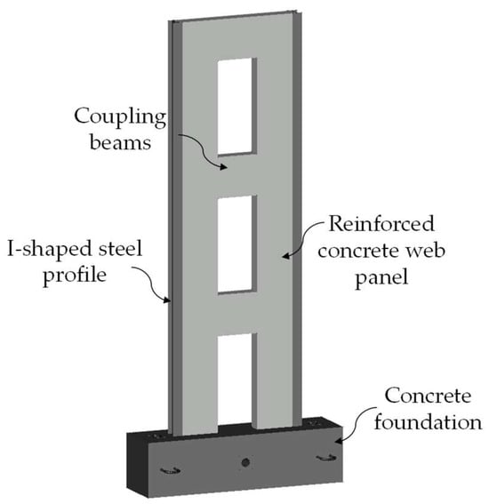
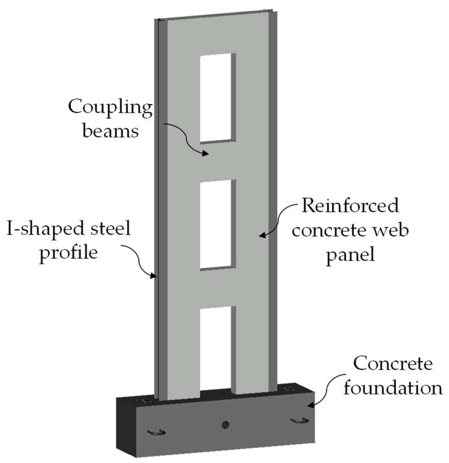
The investigated specimen measures 3000 mm in height and 1000 mm in width and consists of a 100 mm thick reinforced concrete web panel with I-shaped steel profiles partially embedded at the edges. This configuration provides several advantages, as the partially steel profiles facilitate the connection of additional structural components, such as beams or steel plates welded along the height of the wall. The boundary steel profiles embedded at the edges were manufactured using welded steel plates which were fully connected to the web panel of the wall using shear connectors [6]. In Figure 1, the specimen is illustrated. Between the vertical openings, the resulting coupling beams have a length/height ratio of one and were designed with a rectangular cross-section, neglecting the contribution of a reinforced concrete slab. The wall openings are centrally aligned along the height of the specimen and measure 300 × 700 mm, corresponding to 900 × 2100 mm at full scale, and thus represent typical door openings.
Figure 1.
View of the bare CSRCW-21-CO specimen.
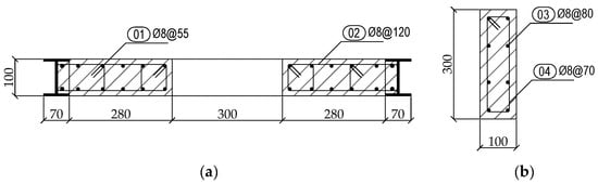
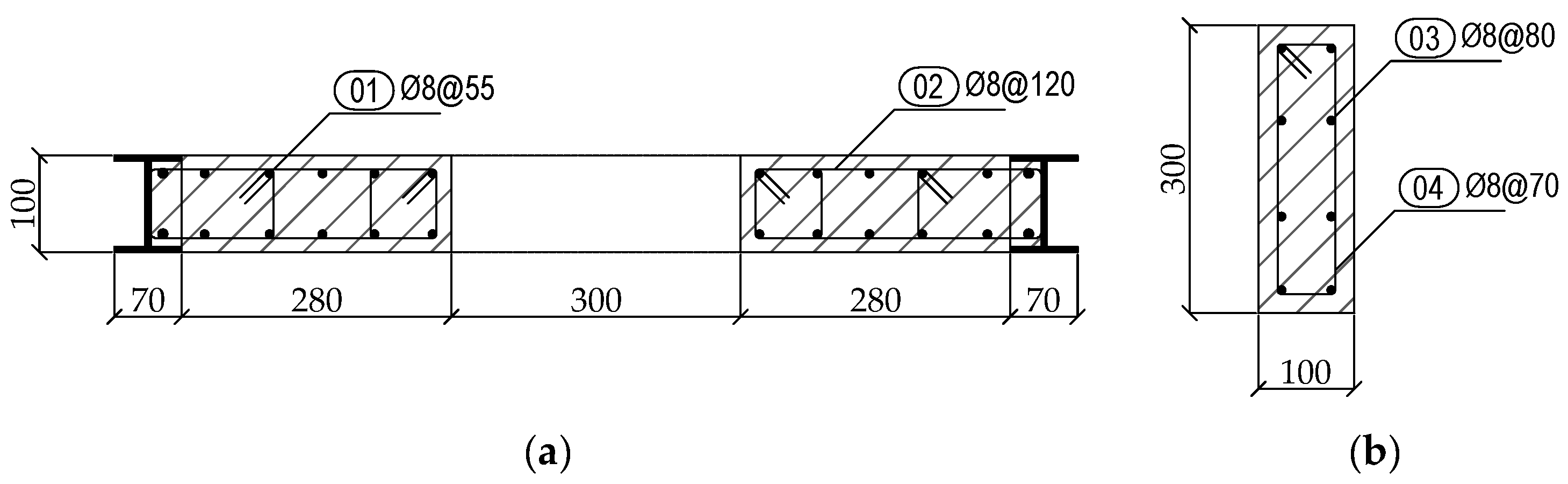
Each vertical pier was longitudinally reinforced with 12 bars of 8 mm diameter and confined by enclosed stirrups spaced at 120 mm along the height of the wall. The boundary stirrups were welded to the steel profiles to prevent any slippage that could occur during experimental testing. The coupling beams were reinforced using orthogonal (conventional) reinforcement cages consisting of eight longitudinal bars of 8 mm diameter and transverse enclosed stirrups spaced at 70 mm along the beam length. In Figure 2, we present the cross-sectional arrangement of vertical piers and coupling beams.
Figure 2.
Cross-section of (a) vertical piers and (b) coupling beams.
2.2. Materials
The concrete strength class specified in the design process of the specimen was C30/37. Based on the experimental tests made on cubic samples at 28 days, the mean characteristic strength in compression obtained was fcm,cube = 49.23 MPa. Standard B500C hot-rolled ribbed steel bars were used to reinforce the concrete web panel of the specimen. Based on laboratory tensile tests performed on reinforcing bar specimens, a mean yield strength of fyk = 530.25 MPa was obtained. The 5.65 mm thick steel plates used to construct the I-shaped steel profiles embedded in the edges of the specimen were made of S460 steel with a characteristic average yielding strength of fyk = 461.34 MPa based on tensile tests.
3. Testing Procedure of the Specimen
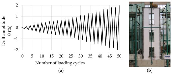
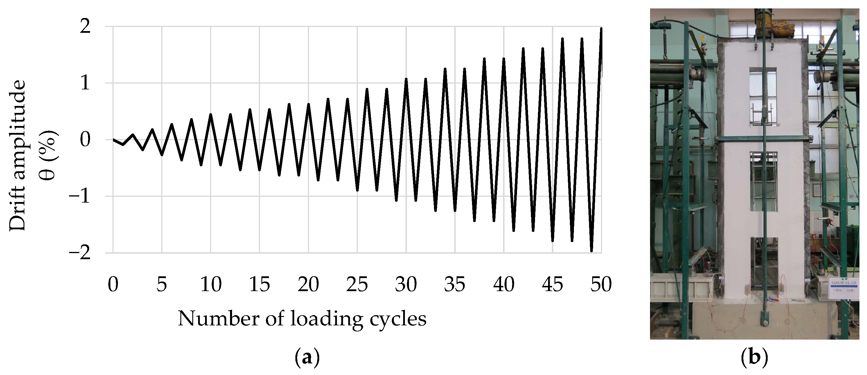
The main objective of the experimental test was to investigate and record the seismic behavior of the specimen (CSRCW-21-CO). Crack propagation, local damage, failure mode, lateral and vertical loads were monitored during the test using testing instrumentation such as displacement transducers, strain gauges and data acquisition systems. The specimen was loaded in both vertical and horizontal direction. The test was performed in displacement control mode according to the loading testing protocol illustrated in Figure 3a by monitoring the total drift amplitude, denoted θ (%). The lateral forces were applied alternatively from left to right to the specimen using two hydraulic jacks positioned 400 mm below the top fiber of the specimen and supported by two triangular steel frames. The drift amplitude was determined as the relative horizontal displacement between the two displacement transducers mounted at the top and bottom of the wall. The vertical distance measured between the transducers along the wall was 2600 mm. The specimen was tested until it reached the ultimate resistance, prior to failure. The test was stopped when the horizontal forces applied to the specimen decreased below 85% of the maximum load reached in both loading directions.
Figure 3.
Testing of the specimen: (a) load—testing protocol and (b) wall setup configuration.
4. Experimental Results
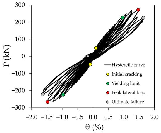
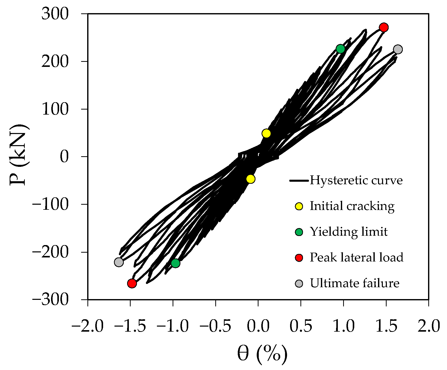
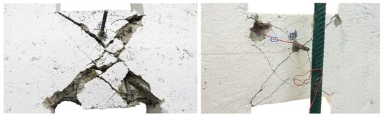
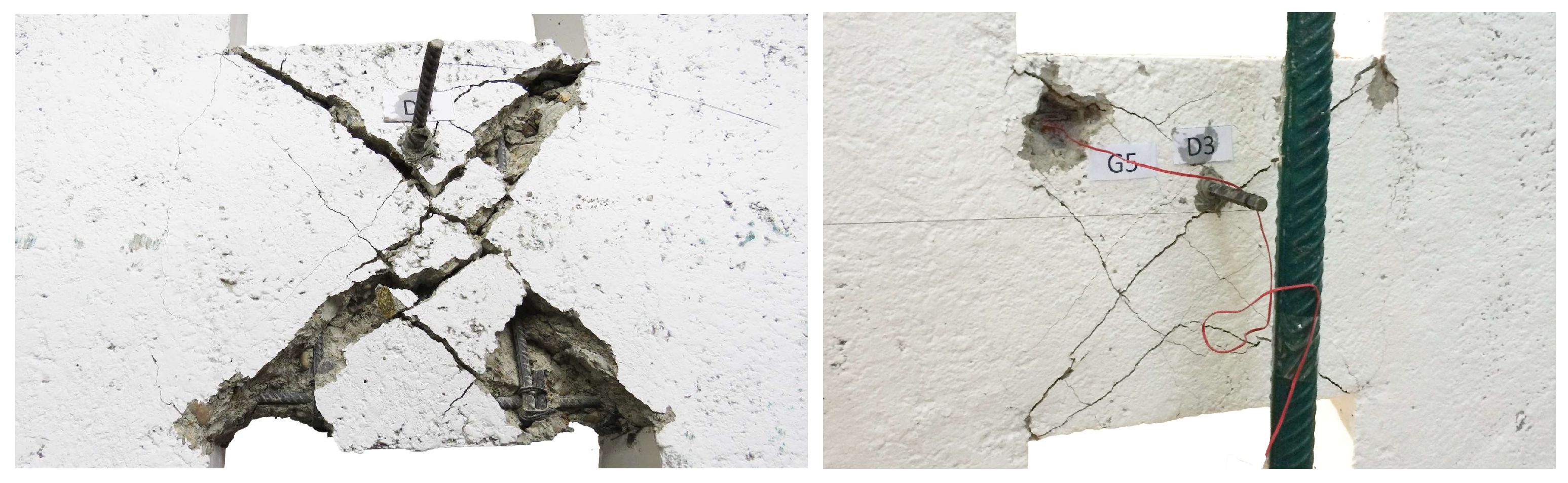
During the experimental test, the seismic response of the hybrid wall (CSRCW-21-CO) was assessed by monitoring its load-bearing capacity, lateral displacement, and damage progression throughout the cyclic loading protocol. Figure 4 presents the hysteretic response in terms of lateral load P (kN) versus lateral drift ratio θ (%). During the cyclic lateral loading, the specimen exhibited a relatively stable and symmetrical hysteretic response in both directions. Nevertheless, the recorded hysteretic loops are relatively narrow near the origin, indicating a moderate pinching effect and a limited energy dissipation capacity of the structural system. The specimen reached peak horizontal loads of approximately +271.6 kN and −266 kN in the positive and negative loading directions, i.e., a nearly symmetrical lateral load-bearing capacity. The drift ratio corresponding to the peak lateral load was approximately θ = 1.47%. After this limit in the behavior was reached, the specimen exhibited a sudden loss of capacity due to the shear failure of the coupling beams. The failure of the coupling beams (Figure 5) was recorded when the drift ratio was approximately θ = 1.63%. Although the coupling beams reached their bearing capacity at this level of lateral drift, the vertical piers at the base of the specimen did not exhibit any structural damage, such as concrete crushing or yielding of the embedded steel profiles. Therefore, a strengthening solution can be applied exclusively to the coupling beams as part of a post-earthquake rehabilitation strategy.
Figure 4.
Hysteretic curve of the tested specimen.
Figure 5.
Failure mode of coupling beams.
5. Strengthening Approach to the Damaged Element
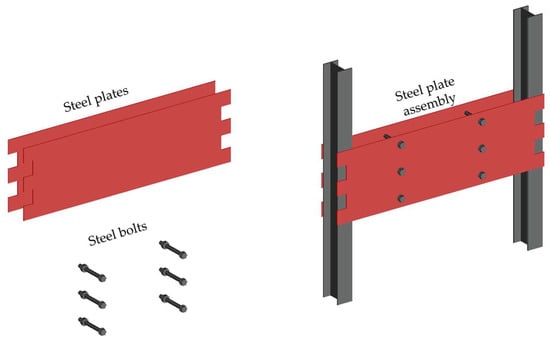
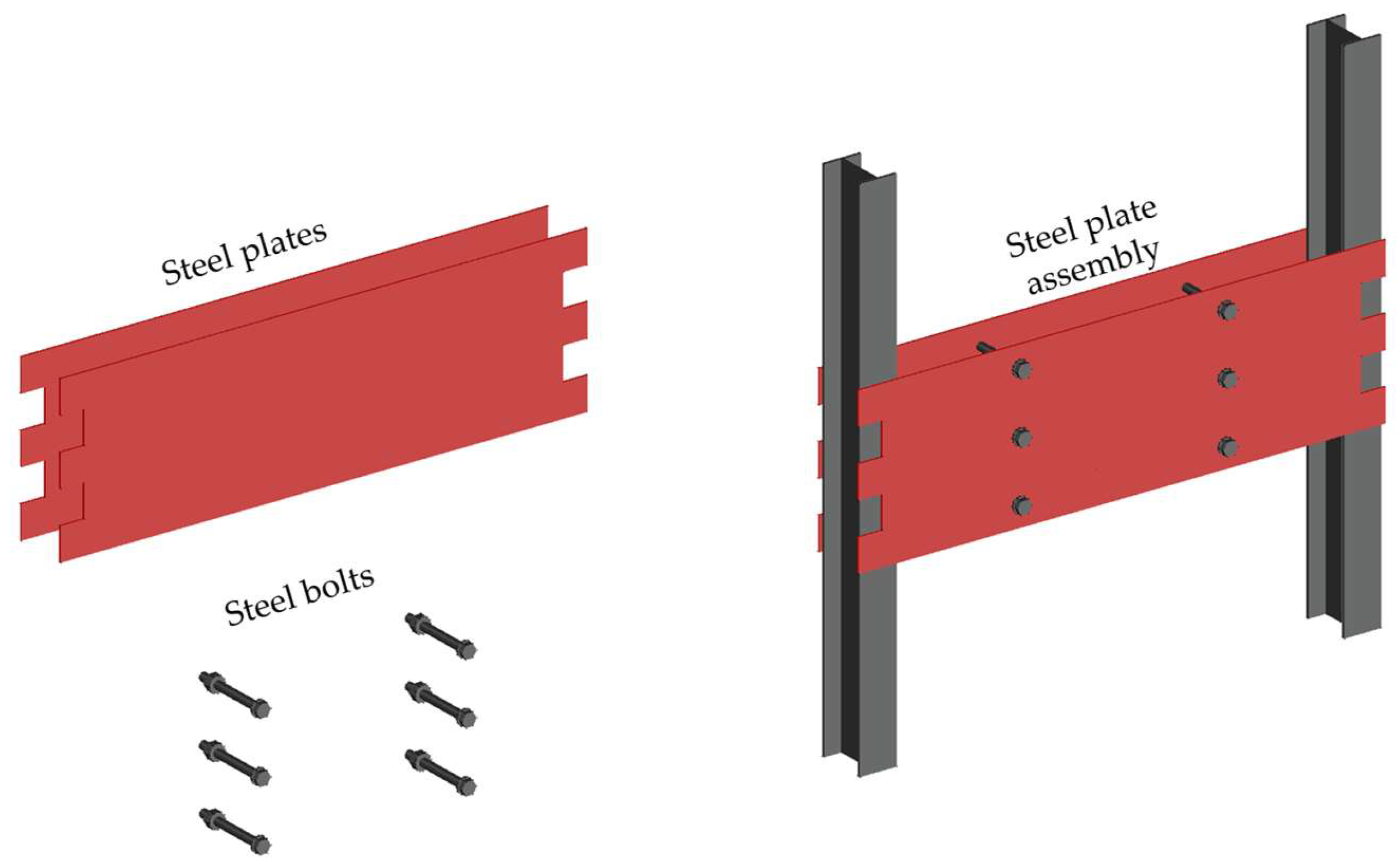
The main objective of the strengthening approach is to restore and enhance the shear and deformation capacity of the coupling beams and to re-establish the strength hierarchy of the wall. A technical advantage of the proposed strengthening solution is that the steel plates can be externally mounted, while their connection to the existing structural element can be achieved using welded connections or steel rods. The solution consists of installing two steel plates on each damaged coupling beam, one on each side of the wall, to replace the existing shear-damaged and spalled concrete, while keeping the reinforcement bars in place. The coupling beams are completely cleaned, and subsequently, the steel plates are mounted on the element. In the literature, most studies investigate this strengthening technique primarily at the level of coupling beams, while its application to hybrid steel–concrete shear walls has been less extensively studied [3,9]. New concrete is cast between the steel plates after previously installment, ensuring adequate compaction and thereby restoring the continuity of the element. The new concrete is of the same strength class, C30/37, as that specified in the design of the initial wall. The height of the plates is equal to the height of the coupling beam (300 mm), while their length covers the entire width of the wall (1000 mm). The plate thickness is 4 mm, and the steel grade selected for the design is S460. A schematic representation of the steel plate assembly is presented in Figure 6.
Figure 6.
Steel plate assembly connected with steel profiles.
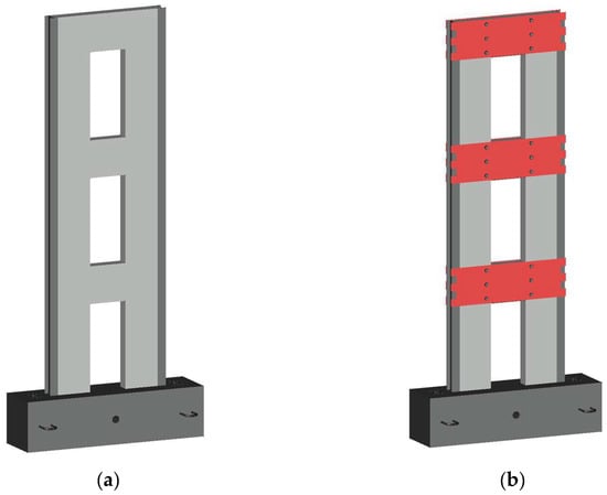
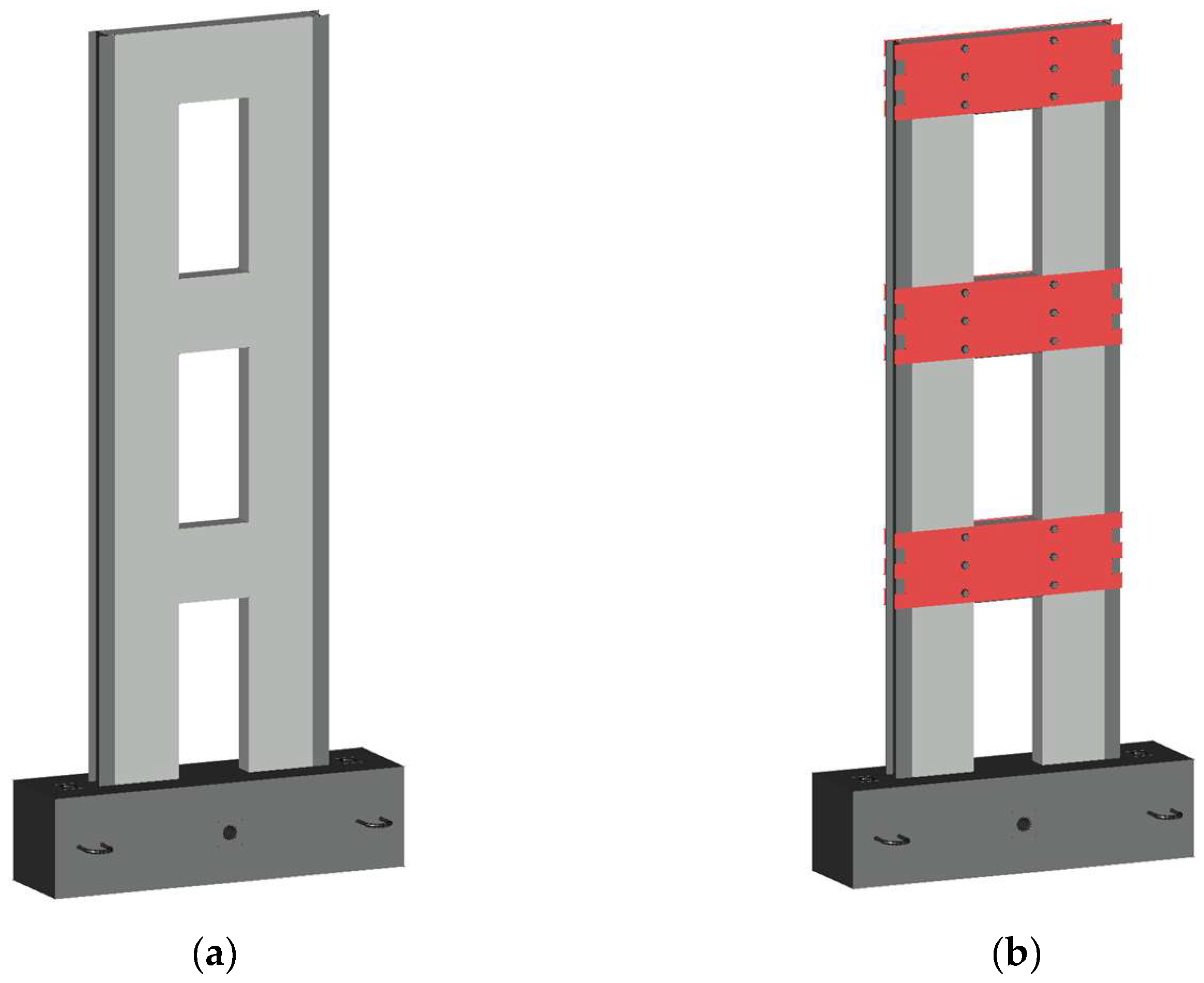
At both ends, the plates are welded on the steel profiles, while across the thickness of the wall pier at the inner face, the plates are interconnected by two sets of three M16 bolts (class 8.8). The boundary regions of the steel plates are locally notched, as in puzzle shapes, to increase the length of the welds and resistance accordingly and to improve the connection of the plates with the embedded steel profiles of the wall. The steel plates are designed to act as the primary shear transfer elements of the strengthened coupling beam. The strengthened coupling beams increase the coupling coefficient between the piers, and therefore the formation of the plastic hinges at the bottom of the piers can be controlled, exploiting the maximum resistance of the steel profiles. Figure 7 illustrates the specimen equipped with the steel plate assembly.
Figure 7.
(a) Bare element and (b) strengthened specimen CSRCW-21-CO-SSP.
6. Finite-Element Analysis
To analyze the proposed strengthening solution, advanced numerical models were created using ATENA (Advanced Tool for Engineering Nonlinear Analysis) 3D Engineering software, version 5.7.0 [10]. The studied specimen, denoted CSRCW-21-CO-SSP, was modelled using three-dimensional volume elements called macro-elements, to more realistically cover the real behavior under state of loading. Between each macro-element generated, a perfect connection was assumed. The reinforcement bars embedded in concrete volumes were modelled as discrete linear elements, only being able to bear tension or compression stresses. The buckling effect of the compressed bars was not included in the analysis.
The foundation block of the specimen was successfully restrained against vertical and horizontal displacements by applying surface and line supports attached to the bottom side of the block. To prevent the base of the wall from overturning, concentrated nodal support was considered on the left edge of the foundation block. The vertical and horizontal forces were applied to the specimen using two additional steel plates mounted at the top part of the wall. The steel plates showed completely elastic behavior (no failure criteria were considered) in the analysis. The additional steel plates, used to strengthen the bare element, were also modelled as macro-elements. Between the external plates, concrete web panel and steel profiles embedded in the edges, a perfect connection was assumed in this analysis.
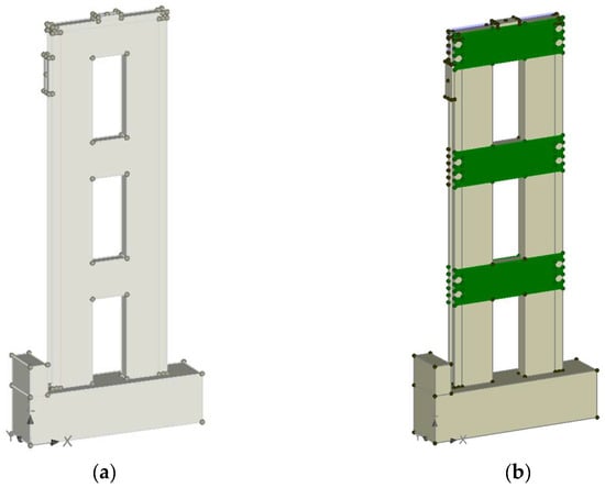
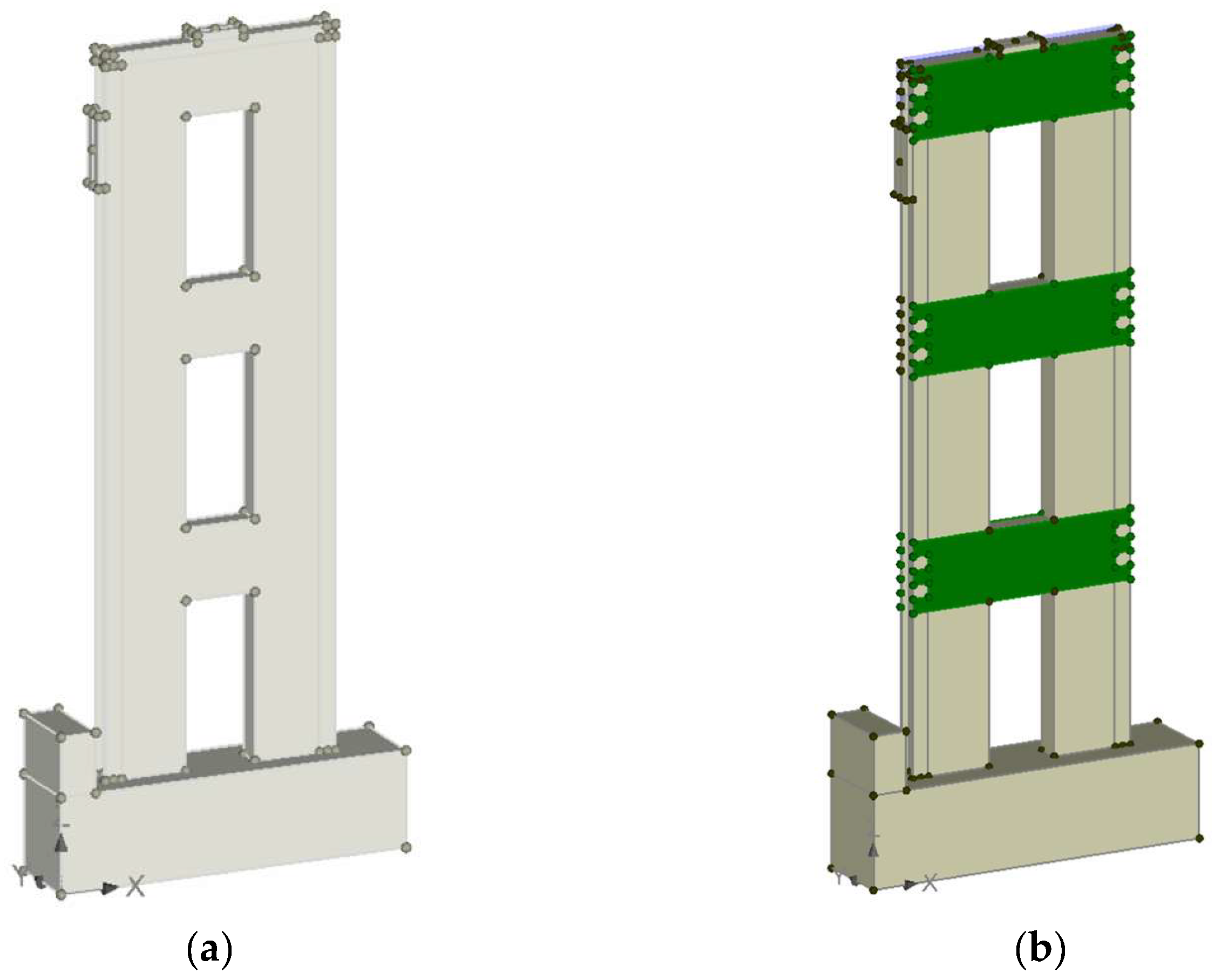
The analyzed three-dimensional models generated using FEM software [10] are presented in Figure 8. The nonlinear behavior of concrete under state of stresses was taken into consideration in the analysis using the “CC3DNonLinCementitious2” SBETA material. The material is capable of simulating the following effects of concrete behavior: failure in tension, crack propagation, stiffness reduction after cracking, nonlinear behavior in compression, etc. A nominal cubic strength of fc = 49.23 MPa was used to simulate the concrete strength grade of C30/37, as considered in the design. The behavior of structural steel (in steel profiles and external steel plates) was assessed using a “3D Steel Bilinear Von Mises” material model.
Figure 8.
Three-dimensional models (a) before strengthening and (b) after strengthening using external steel plates.
This material covers the Von Mises failure criteria and is used to cover the elastic and plastic behavior of steel in tension and compression. The yielding limit considered in the analysis was fy = 465 MPa, while the hardening modulus was H = 2100 MPa. For steel reinforcements, a multilinear stress–strain law was defined to cover the tensile behavior correlated with the tensile curves obtained experimentally. Isoparametric three-dimensional, quadratic, solid “CCIsoTetra” elements were used as finite elements. The chosen size of each finite element was 0.08 m. These dimensions of the FE mesh were considered to obtain better time efficiency and accurate results in the analysis of numerical models and to cover the behavior of the specimens. Nonlinear behavior was obtained by performing the analysis in displacement control mode, recording the pushover curve in one direction for each analyzed model.
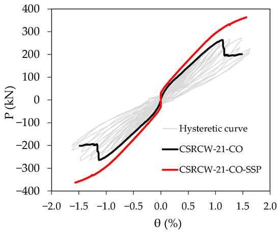
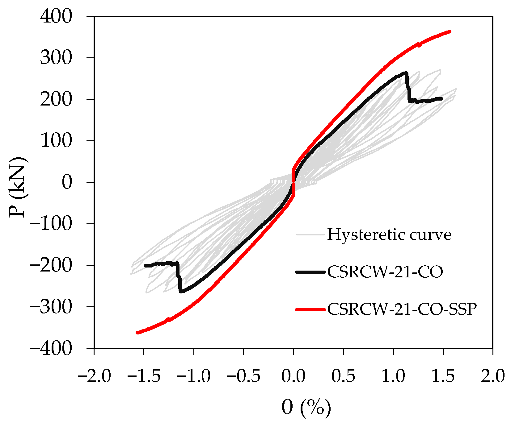
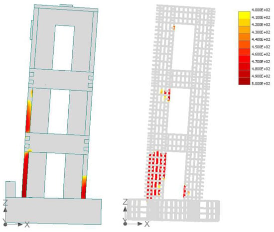
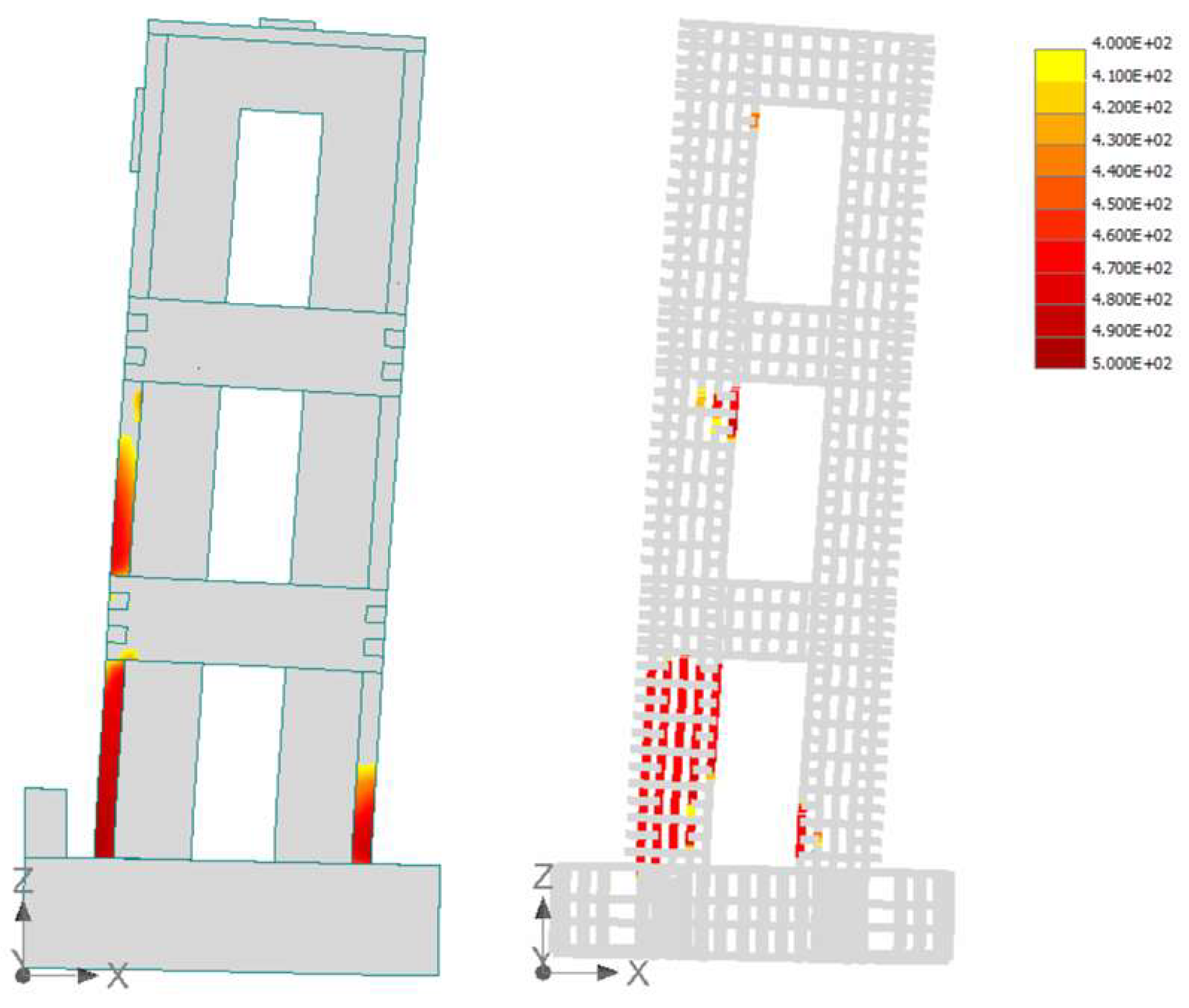
In Figure 9, the envelope curves obtained numerically are presented for both analyzed models. The seismic behavior of the analyzed specimen in the unstrengthened case is captured with superior accuracy by the numerical model, including the brittle failure mode characterized by the sudden drop in load-bearing capacity. As can be observed, the proposed strengthening solution was able to restore and enhance the initial behavior of the specimen. The load-bearing capacity of the wall is expected to increase by approximately 35% after the strengthening of coupling beams with puzzled steel plates. While the experimental results for the initial specimen showed that no significant plastic deformations developed in the steel profiles at the base of the wall, the numerical simulation of the strengthened specimen indicated yielding of the steel profile subjected to tension after the installation of the external steel plates (Figure 10). Consequently, the energy dissipation capacity of the structural system is expected to improve.
Figure 9.
Pushover curves of the specimens before and after strengthening.
Figure 10.
Development of Von Mises stress in steel profiles and steel reinforcements for the strengthened element CSRCW-21-CO-SSP.
7. Conclusions
This paper aimed to present a possible approach to strengthening hybrid steel–concrete shear walls with centered openings using external steel plates. The strengthening solution focuses on restoring and enhancing the behavior of shear-damaged reinforced concrete coupling beams but also could improve the general seismic behavior of the wall. The solution indicates that relatively few technologic steps are needed to restore the integrity of the damaged coupling beams and increase their strength. The external plates can be mounted by fillet welds but also using steel rods, as the partial steel profiles facilitate the connection of additional structural components, such as beams or steel plates, along the height of the wall. Alongside experimental results, FEM analyses were performed to cover the behavior of the specimen after mounting additional steel plates. The numerical approach included several numerical simplifications of the models generated in the analysis, but accurate results were obtained to simulate the real behavior of the tested specimen. The following conclusions can be drawn based on experimental and numerical observations.
- The structural strengthening solution proposed for the element was able to improve the initially low-dissipative behavior of the wall, increasing its load-bearing capacity and energy dissipation capacity.
- The additional steel plates improved the post-elastic behavior of the system, enhancing its capacity to dissipate seismic energy during earthquakes.
- The numerical models can reproduce the investigated structural behavior of the specimen with sufficient accuracy, providing a preliminary framework for further numerical and experimental studies.
The authors acknowledge that the strengthened specimen has been evaluated only through numerical analyses based on several simplifying assumptions adopted to capture its global seismic response. In the next step of the experimental program, the proposed solution will be applied, and the experimental test will be performed. It is expected that the behavior of the strengthened element will follow the numerical results obtained.
Author Contributions
Conceptualization, D.D., V.T., and A.J.; methodology, S.-C.F., and V.T.; validation, V.T., A.J., D.D., V.-Ș.P., and S.-C.F.; investigation, V.T., and A.J.; writing—original draft preparation, V.T., and A.J.; writing—review and editing, D.D., S.-C.F., V.T., V.-Ș.P., and A.J.; visualization, V.T., A.J., V.-Ș.P., D.D., and S.-C.F.; supervision, D.D., S.-C.F., and V.T.; project administration, D.D., V.T., and S.-C.F.; funding acquisition, D.D., and V.-Ș.P. All authors have read and agreed to the published version of the manuscript.
Funding
This research received no external funding.
Institutional Review Board Statement
Not applicable.
Informed Consent Statement
Not applicable.
Data Availability Statement
The raw data supporting the conclusions of this article will be made available by the authors on request.
Acknowledgments
The present work is part of the proposed research grant submitted for evaluation to UEFISCDI project number PN-IV-P1-PCE-2026-0046, entitled ‘‘INtegrated hybrid steel-Concrete REinforced systems for Adaptive Sustainable and Earthquake resilient infrastructure—INCREASE”. Participation in the 15th Central European Congress on Concrete Engineering, held in Vodice, Croatia, was supported by the project CNFIS-FDI-2026-F-0613, entitled “International@UPT—Strengthening UPT’s International Orientation through Participation in International Events, Mobility Programmes, and Digitalization”. During the preparation of this manuscript, the authors used ChatGPT 5.6 (OpenAI) to assist with language refinement and structural clarity. The authors have reviewed and edited the output and take full responsibility for the content of this publication.
Conflicts of Interest
The authors declare no conflicts of interest.
Abbreviations
The following abbreviations are used in this manuscript:
| CSRCW-CO | Composite steel-reinforced concrete wall–centered openings |
| SSPs | Strengthening steel plates |
References
- Nie, J.-G.; Hu, H.-S.; Eatherton, M.R. Concrete-filled steel plate composite coupling beams: Experimental study. J. Constr. Steel Res. 2014, 94, 49–63. [Google Scholar] [CrossRef] [Scilit]
- Lam, W.-Y.; Su, R.K.-L.; Pam, H.-J. Experimental study on embedded steel plate composite coupling beams. J. Struct. Eng. 2005, 131, 1294–1302. [Google Scholar] [CrossRef] [Scilit]
- Su, R.K.L.; Zhu, Y. Experimental and numerical studies of external steel plate strengthened reinforced concrete coupling beams. Eng. Struct. 2005, 27, 1537–1550. [Google Scholar] [CrossRef] [Scilit]
- Nagy-György, T.; Dăescu, A.C.; Călbas, C. Strengthening of shear walls’ coupling beams using steel plates. In Proceedings of the Nemzetközi Építéstudományi Konferencia–ÉPKO, Șumuleu Ciuc, Romania, 4–7 June 2026; pp. 136–141. [Google Scholar] [CrossRef]
- Cheng, B.; Yang, C.; Su, R.K.L. Seismic retrofit analysis of concrete coupled shear wall structures with laterally restrained steel plate coupling beams. Adv. Struct. Eng. 2018, 21, 962–974. [Google Scholar] [CrossRef] [Scilit]
- Chung, P.-T.; Chou, C.-C. One-sided shear retrofit of reinforced concrete beams in existing high-rise buildings. Eng. Struct. 2022, 252, 113634. [Google Scholar] [CrossRef] [Scilit]
- Dan, D.; Fabian, A.; Stoian, V. Theoretical and experimental study on composite steel–concrete shear walls with vertical steel encased profiles. J. Constr. Steel Res. 2011, 67, 800–813. [Google Scholar] [CrossRef] [Scilit]
- Todea, V.; Dan, D.; Floruț, S.-C.; Stoian, V. Experimental investigations on the seismic behavior of composite steel–concrete coupled shear walls with central openings. Structures 2021, 33, 878–896. [Google Scholar] [CrossRef] [Scilit]
- International Journal of Advanced Steel Construction, Volume 12, Issue 2. Available online: https://www.ascjournal.com/index.php?option=com_djcatalog2&view=item&id=55:vol12no2&cid=14:2016&Itemid=649 (accessed on 17 August 2026).
- Cervenka Consulting. ATENA—Advanced Tool for Engineering Nonlinear Analysis. Available online: https://www.cervenkaconsulting.com/products/atena/ (accessed on 17 August 2026).
Disclaimer/Publisher’s Note: The statements, opinions and data contained in all publications are solely those of the individual author(s) and contributor(s) and not of MDPI and/or the editor(s). MDPI and/or the editor(s) disclaim responsibility for any injury to people or property resulting from any ideas, methods, instructions or products referred to in the content. |
© 2026 by the authors. Licensee MDPI, Basel, Switzerland. This article is an open access article distributed under the terms and conditions of the Creative Commons Attribution (CC BY) license.