


Abstract
This paper presents the results of an experimental investigation related to the influence of opening arrangement on the cyclic response of reduced-scale hybrid steel–concrete walls incorporating steel-fiber-reinforced concrete. The experimental specimens had similar structural configurations but differed in the positioning of the door openings, which were either centered or staggered over the height of the wall. Both walls were subjected to constant axial loading and subjected to cyclic lateral loads under displacement control. The centered-opening specimen exhibited progressive cracking, gradual strength degradation, and greater deformation capacity, with failure governed by the coupling beams. Conversely, the staggered arrangement interrupted the continuity of the conventional reinforcement and led to failure of an intermediate pier, where the local fiber distribution was insufficient. The findings demonstrate that fibers should only complement continuous conventional reinforcement, particularly in critical regions influenced by opening configuration.
1. Introduction
Reinforced concrete structural walls are widely used in high-rise buildings located in regions of high seismicity due to their high shear strength and stiffness. As reported in several studies [1,2,3,4], hybrid steel–concrete walls represent an effective solution for improving the seismic behavior of high-rise structures. Within such systems, steel-fiber-reinforced concrete (SFRC) may be used as an alternative to conventionally reinforced concrete, as steel fibers can delay crack propagation and improve the overall cracking behavior of structural elements [5,6,7]. However, architectural requirements often require the introduction of openings in structural walls, which may be arranged in different configurations and staggered over the height of the building. Accordingly, the present paper presents an experimental investigation related to the influence of opening arrangement on the structural behavior of hybrid steel–concrete walls incorporating SFRC. An additional objective of the experimental program was to evaluate the effectiveness of dispersed steel fibers as a substitute for conventional reinforcement bars within the concrete panels. Conventional reinforcing cages were retained around the openings and within the coupling beams, while the remaining panel regions relied primarily on fiber reinforcement.
2. Experimental Research Program
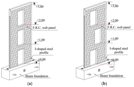
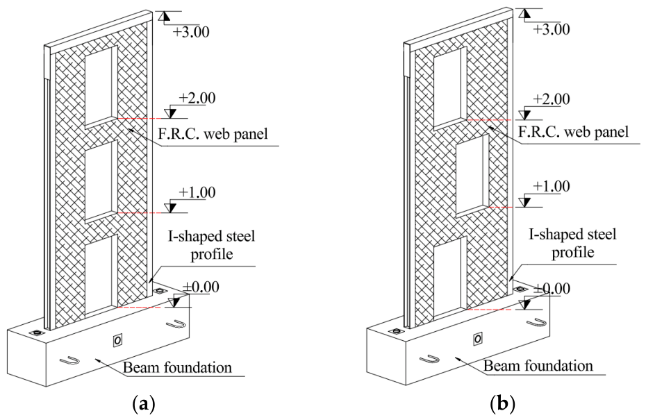
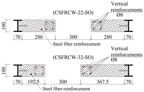
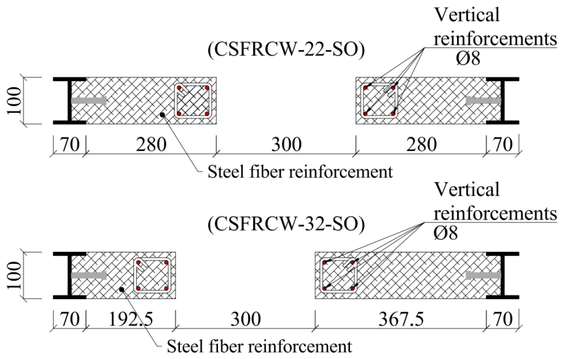
The study presented herein is part of a wider research program conducted at the Faculty of Civil Engineering of Politehnica University Timișoara. The program investigates the behaviour of hybrid steel–concrete shear walls with different reinforcement layouts and opening configurations [8,9], with the aim of identifying the advantages and limitations of these structural systems and formulating relevant design recommendations. The investigation reported in this paper compares the behaviour of two SFRC shear walls tested until failure: CSFRCW-22-CO, featuring centered openings, and CSFRCW-32-SO, featuring staggered openings. The general view and cross-section of the specimens are presented in Figure 1 and Figure 2.
Figure 1.
Perspective view of: (a) CSFRCW-22-CO; (b) CSFRCW-32-SO.
Figure 2.
Cross-section of the specimens.
2.1. Experimental Specimens
Both specimens were 1:3-scale hybrid steel–concrete walls consisting of a steel-fiber-reinforced concrete panel and steel boundary profiles fabricated from steel welded plates. The concrete panels incorporated scaled door openings corresponding to dimensions of 900 × 2100 mm. Conventional reinforcing cages, consisting of longitudinal bars and stirrups, were provided around the openings, while the coupling beams were similarly reinforced. In both specimens, composite action between the concrete panel and the partially encased steel boundary profiles was ensured by welded Nelson headed studs embedded in the concrete. The studs assure a full connection between the web panel and steel profile.
2.2. Materials
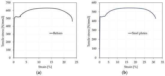
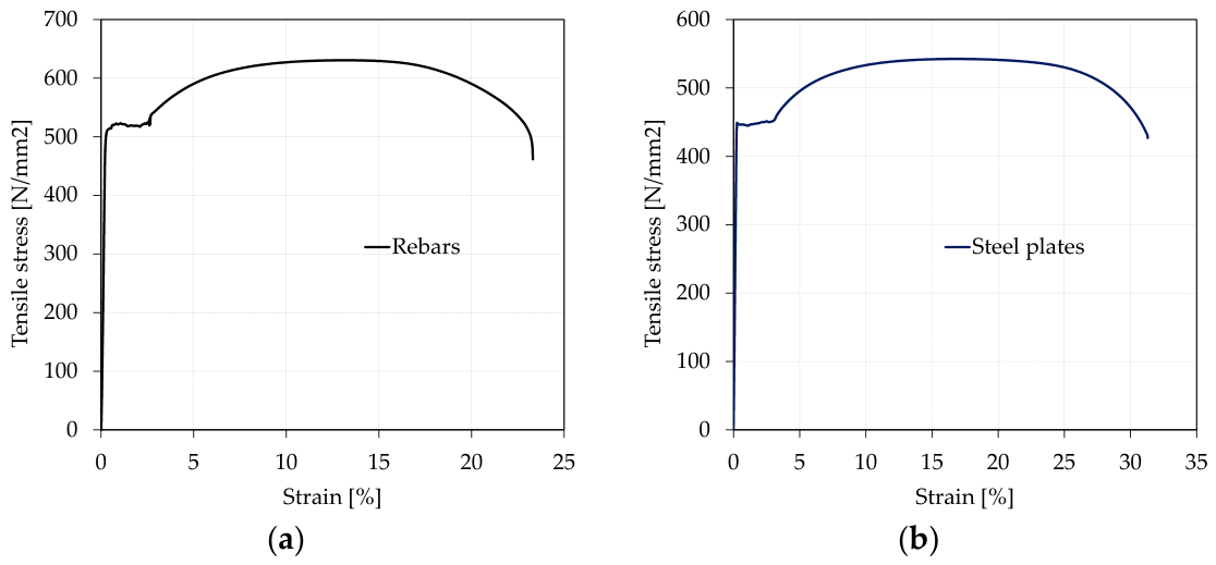
The mechanical characteristics of the materials used were tested on samples of concrete and steel. The web panels were cast using C30/37 concrete, as confirmed by 28-day compression tests on 150 mm cubes. The boundary steel profiles were fabricated from welded S460 steel plates with a thickness of 5.65 mm, while B500C steel was used for conventional reinforcement. The results of tensile tests on samples of rebars and steel plates are presented in Figure 3.
Figure 3.
Strain–stress curve for: (a) rebars; (b) steel plates.
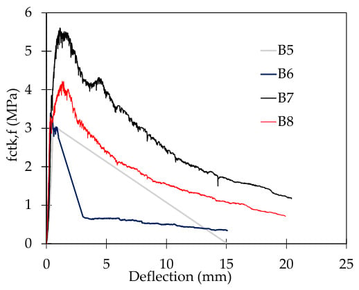
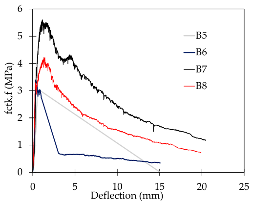
Hooked-end steel fibers, 60 mm long and 0.8 mm in diameter, with a characteristic tensile strength of approximately 1100 MPa, were added at a dosage of about 40 kg/m3. Prism tests were conducted to characterize the fiber-reinforced concrete response. As shown by the stress–strain curves in Figure 4 [9], differences in the specimen responses indicate that a fully uniform distribution of fibers was not achieved during casting.
Figure 4.
Behavior curves of the fiber-reinforced concrete prisms [9].
2.3. Test Setup and Instrumentation
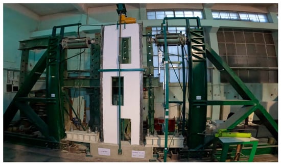
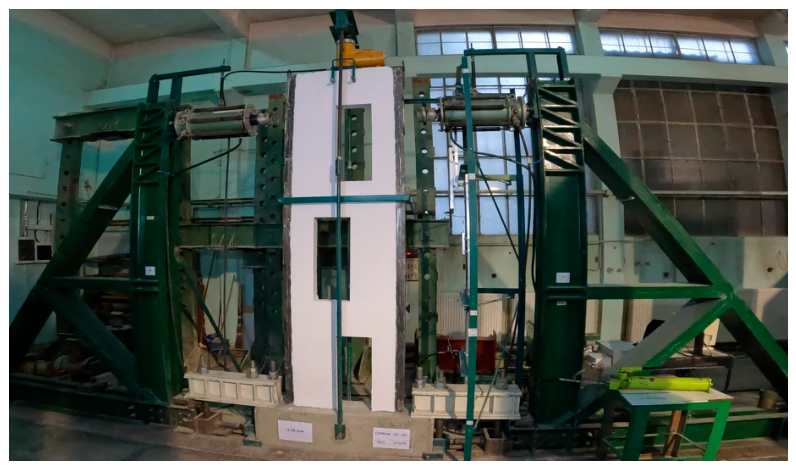
The specimens were subjected to constant axial loading and cyclic lateral forces using one vertical and two horizontal hydraulic actuators mounted on a double-sided reaction frame. An independent bracing system restrained out-of-plane movement. Displacement transducers monitored the in-plane and out-of-plane response, while strain gauges attached to the flanges and webs of the boundary profiles recorded local strains. The drift presented in this study represents the total drift, defined as the difference between the displacement at the top and the displacement at the base. Both specimens were tested to failure under the displacement controlled. The detailed loading protocol was described in [9]. A general view of the test set up is presented in Figure 5.
Figure 5.
General view of the experimental setup.
3. Experimental Results
3.1. Hysteretic Curves
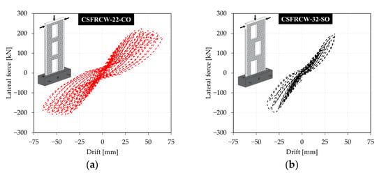
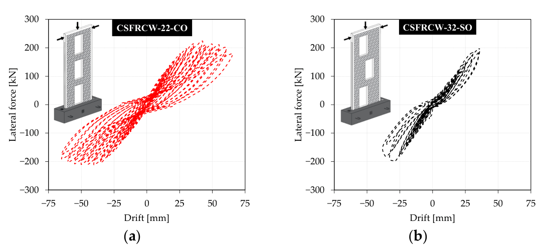
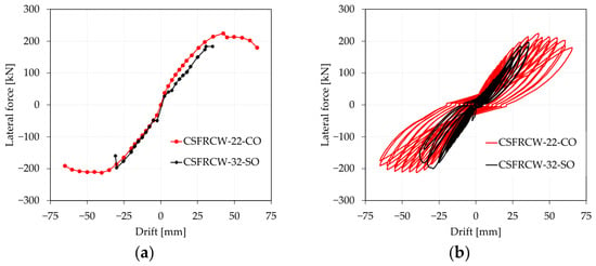
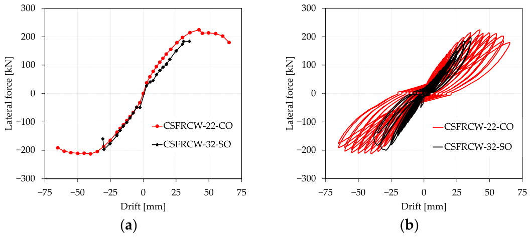
The specimen with centered openings CSFRCW-22-CO reached a peak lateral force of approximately 224 kN and a maximum drift of 65.4 mm, whereas the specimen with staggered openings CSFRCW-32-SO attained approximately 197 kN and 35 mm, respectively. The hysteretic curves for both elements are presented in Figure 6. Compared with the staggered-opening specimen, the centered-opening wall developed 13.7% greater lateral resistance and reached an 86.9% larger maximum drift. The centered arrangement therefore provided both higher strength and a considerably greater deformation capacity, as we can see in Figure 7. Moreover, the ability of this specimen to sustain cyclic loading over a wider displacement range indicates a potentially greater capacity for energy dissipation.
Figure 6.
Hysteretic curves—lateral force-drift for: (a) CSFRCW-22-CO; (b) CSFRCW-32-SO.
Figure 7.
Lateral force-drift curves of CSFRCW-22-CO and CSFRCW-32-SO: (a) envelope; (b) hysteretic.
3.2. Crack Patterns and Failure Mechanisms
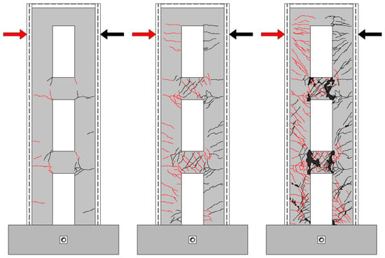
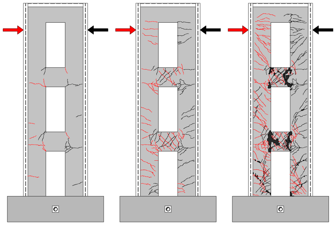
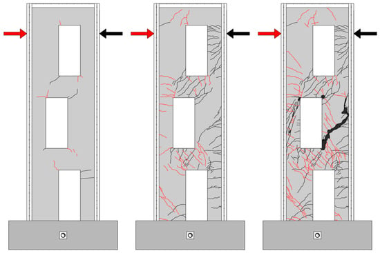
The cracks developed at relatively low displacement levels in both specimens, with visible cracks recorded during the 5 mm loading cycles. For the wall with centered openings (CSFRCW-22-CO), damage subsequently developed mainly within the coupling beams, following the expected load-transfer mechanism. Although cracking initiated during the early loading stages, failure did not occur suddenly. Instead, the existing cracks widened progressively over successive cycles until the coupling beams could no longer sustain the imposed lateral load. The gradual development of damage, together with the limited concrete spalling observed at failure, indicates that the steel fibers contributed to maintaining the integrity of the cracked concrete. The crack distribution on different stages of the tested element is presented in Figure 8.
Figure 8.
Crack pattern of CSFRCW-22-CO at initial cracking, peak load, and failure stages.
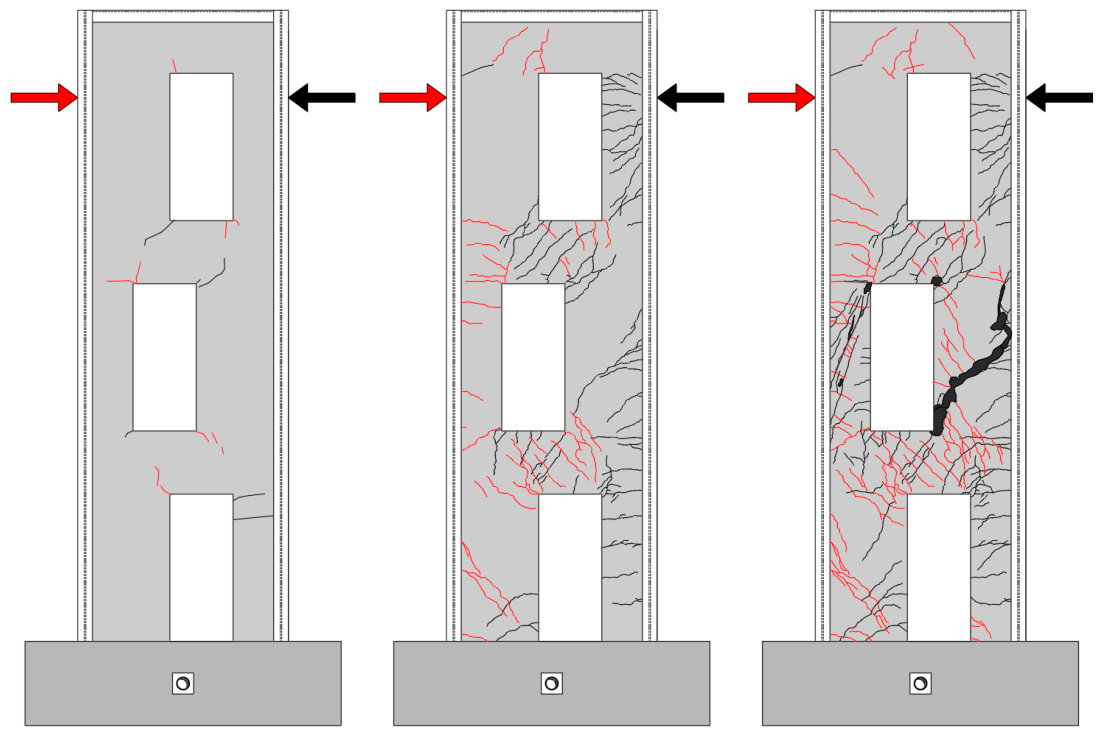
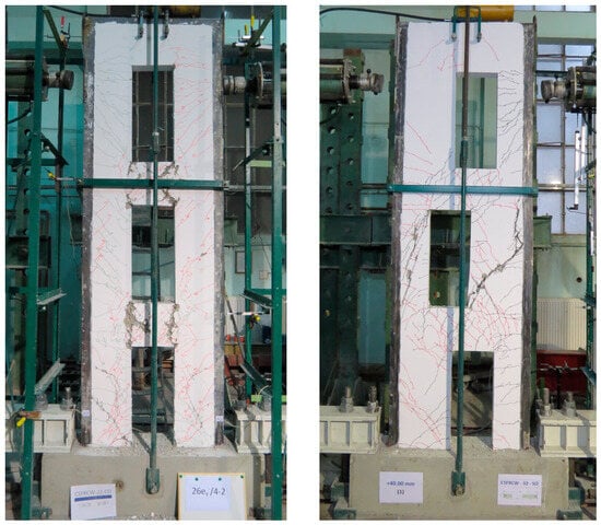
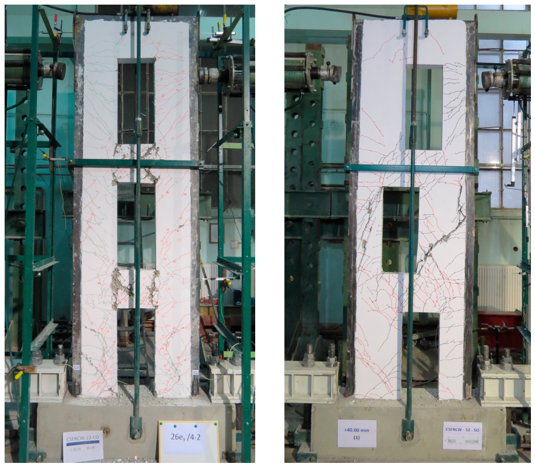
The staggered-opening specimen (CSFRCW-32-SO) exhibited a broadly similar cracking response during the initial stages, as illustrated in Figure 9. However, it reached failure considerably earlier than the centered-opening wall, in agreement with the response recorded by the hysteretic curves. Final failure was governed by the deterioration of the first-story intermediate pier. This region contained no conventional reinforcing cage, while examination of the damaged concrete indicated a locally insufficient fiber content. Although the nominal fiber dosage was carefully controlled during mixing, a uniform distribution throughout the wall could not be fully ensured during casting. The observed failure therefore highlights an important practical limitation of steel-fiber-reinforced concrete: local variations in fiber distribution may significantly affect the response of critical regions that rely exclusively on dispersed reinforcement. Figure 10 presents a comparison of the final failure modes and crack distribution of the tested specimens.
Figure 9.
Crack pattern of CSFRCW-32-SO at initial cracking, peak load, and failure.
Figure 10.
Final damage patterns of CSFRCW-22-CO and CSFRCW-32-SO.
4. Conclusions
The two specimens developed distinct failure mechanisms during testing. In the centered-opening wall, damage progressively concentrated in the coupling beams, which ultimately governed the failure of the specimen. In contrast, the response of the staggered-opening wall was controlled by the failure of a first-story intermediate pier, before comparable damage could develop in the coupling beams.
The steel fibers had a beneficial effect on the post-cracking response of both walls. They helped maintain the integrity of the concrete after the formation of wide cracks, limiting spalling and preventing the sudden detachment of concrete fragments.
The major difference in deformation capacity cannot be attributed solely to the opening arrangement. In CSFRCW-22-CO, the centered openings allowed the conventional reinforcing cages located along their sides to remain continuous over the wall height.
In CSFRCW-32-SO, the staggered arrangement interrupted this reinforcement path because the cages followed the perimeter of each opening and finished within the coupling-beam regions. Consequently, parts of the intermediate piers relied mainly on dispersed fibers. The locally insufficient fiber content observed in the first-story pier resulted in its failure and restricted the displacement capacity of the wall. As a result, the centered-opening specimen reached an 86.9% larger maximum drift and 13.7% greater lateral resistance.
The pier failure observed in CSFRCW-32-SO indicates that dispersed steel fibers cannot fully substitute conventional bar reinforcement in critical structural regions. Even when the nominal fiber dosage is carefully controlled, the casting process may result in a nonuniform distribution and create local zones with insufficient reinforcement. A minimum amount of continuous conventional reinforcement should therefore be maintained along the main load-transfer paths. Steel fibers can instead be used as supplementary reinforcement to improve crack control, preserve post-cracking concrete integrity, and limit concrete spalling.
Author Contributions
Conceptualization, D.D. and V.-Ș.P.; methodology, S.-C.F. and V.T.; validation, V.-Ș.P., V.T., D.D. and S.-C.F.; investigation, V.-Ș.P. and V.T.; writing—original draft preparation, V.-Ș.P., V.T. and D.D.; writing—review and editing, D.D., S.-C.F., V.T. and A.J.; visualization, V.-Ș.P., D.D., S.-C.F., V.T. and A.J.; supervision, D.D., S.-C.F. and V.T.; project administration, D.D., V.T. and S.-C.F.; funding acquisition, D.D. and V.-Ș.P. All authors have read and agreed to the published version of the manuscript.
Funding
This research received no external funding.
Institutional Review Board Statement
Not applicable.
Informed Consent Statement
Not applicable.
Data Availability Statement
The raw data supporting the conclusions of this article will be made available by the authors on request.
Acknowledgments
The presented work is part of the proposal research grant submitted for evaluation to UEFISCDI project number PN-IV-P1-PCE-2026-0046, entitled “INtegrated hybrid steel-Concrete REinforced systems for Adaptive Sustainable and Earthquake resilient infrastructure—INCREASE”. Participation in the 15th Central European Congress on Concrete Engineering, held in Vodice, Croatia, was supported by the project CNFIS-FDI-2026-F-0613, entitled “International@UPT—Strengthening UPT’s International Orientation through Participation in International Events, Mobility Programmes, and Digitalization”. During the preparation of this manuscript, the authors used ChatGPT 5.6 (OpenAI) to assist with language refinement and structural clarity. The authors have reviewed and edited the output and take full responsibility for the content of this publication.
Conflicts of Interest
The authors declare no conflicts of interest.
Abbreviations
The following abbreviations are used in this manuscript:
| SFRC | Steel-fiber-reinforced concrete |
| CSFRCW CO/SO | Composite steel-fiber-reinforced concrete wall—centered/staggered openings |
References
- Mo, J.; Uy, B.; Li, D.; Thai, H.-T.; Tran, H. A review of the behaviour and design of steel–concrete composite shear walls. Structures 2021, 31, 1230–1253. [Google Scholar] [CrossRef] [Scilit]
- Astaneh-Asl, A. Seismic Behavior and Design of Composite Steel Plate Shear Walls; Department of Civil and Environmental Engineering, University of California: Berkeley, CA, USA, 2002. [Google Scholar]
- Arabzadeh, A.; Soltani, M.; Ayazi, A. Experimental investigation of composite shear walls under shear loadings. Thin-Walled Struct. 2011, 49, 842–854. [Google Scholar] [CrossRef] [Scilit]
- Plumier, A.; Degée, H. Design of Hybrid Structures: Where Steel Profiles Meet Concrete, 1st ed.; CRC Press: London, UK, 2023. [Google Scholar]
- Zhang, H.; Sharhan, A.; Wang, J.; Chen, Z. Seismic performance and shear capacity prediction of SFRC shear walls with different door openings. Structures 2025, 72, 108198. [Google Scholar] [CrossRef] [Scilit]
- Li, X.; Gao, N.; Zhao, J.; Yin, L. Study on seismic performance of steel fiber reinforced concrete shear walls with hybrid steel strands and HRB400 bars in the boundary elements. Constr. Build. Mater. 2024, 430, 136447. [Google Scholar] [CrossRef] [Scilit]
- Zhang, J.; Cai, R.; Liu, W.; Peng, C. Cyclic Behavior of Steel Fiber-Reinforced High-Strength Concrete Shear Walls with High-Strength Steel Bars. Int. J. Civ. Eng. 2025, 23, 1717–1733. [Google Scholar] [CrossRef] [Scilit]
- Dan, D.; Fabian, A.; Stoian, V. Theoretical and experimental study on composite steel–concrete shear walls with vertical steel encased profiles. J. Constr. Steel Res. 2011, 67, 800–813. [Google Scholar] [CrossRef] [Scilit]
- Todea, V.-C. Performanța seismică a pereților compoziți oțel-beton cu goluri centrale (ENG: Seismic Performance of Steel–Concrete Composite Walls with Central Openings); Editura Politehnica Timişoara: Timisoara, Romania, 2021. [Google Scholar]
Disclaimer/Publisher’s Note: The statements, opinions and data contained in all publications are solely those of the individual author(s) and contributor(s) and not of MDPI and/or the editor(s). MDPI and/or the editor(s) disclaim responsibility for any injury to people or property resulting from any ideas, methods, instructions or products referred to in the content. |
© 2026 by the authors. Licensee MDPI, Basel, Switzerland. This article is an open access article distributed under the terms and conditions of the Creative Commons Attribution (CC BY) license.