


Abstract
Through different concepts of bridge design, we can significantly influence its seismic behavior. Earthquake energy can be either concentrated on one critical element (causing it to suffer the most damage), distributed among more of them equally (to minimize the damage), or mitigated through isolation or external dissipation. Internal dissipation of energy will occur within the structure, through plastic deformation, which will cause yielding and cracking damage in the critical sections. External dissipation is possible by implementing various seismic damping devices. Distribution and/or dissipation of energy can be controlled by implementing various solutions of bridge bearing layout, introduction of damping or isolation in the form of special bearing devices (seismic protection system), and correct dimensioning of the elements (section area and stiffness, reinforcement placement). The behavior of the bridge structure is thus adapted to the dynamic nature of the earthquake depending on its location. In this paper, different types of seismic behavior of the bridge will be explored, ranging from dissipative systems (limited ductile behavior of bridge elements) to shock transmitter devices and seismic isolation systems. A case study of a continuous box girder composite bridge with high reinforced concrete columns is analyzed for different bearing layouts (differing in the number of fixed points on the columns), and alternatively with a seismic isolation system. The dynamic properties of each alternative and their consequences on bridge design will be compared. Insight into the advantages and disadvantages of each variant is given.
1. Introduction
Bridges transfer horizontal seismic forces primarily through the substructure components, particularly the columns. Seismic action is commonly represented as an imposed loading that generates internal forces and corresponding displacements within structural elements. Such a design approach requires adequate stiffness and strength while ensuring sufficient ductility of the structural components. Under seismic load, selected structural components may reach their yield strength, resulting in the formation of plastic hinges through which seismic energy is dissipated by controlled inelastic deformation. In bridge structures, plastic hinges should preferably develop within the columns rather than the superstructure. This design philosophy aims to limit seismic damage in predetermined and appropriately detailed ductile regions while preserving the integrity of the superstructure. Maintaining the superstructure essentially undamaged is particularly important for ensuring the post-earthquake functionality of the bridge and continuity of traffic, especially where the bridge forms part of a critical transportation route. In addition to the conventional seismic design approach based on the ductile behavior of bridge columns, which may in some cases result in disproportionately large substructure dimensions and consequently high construction and post-earthquake repair costs, the seismic performance of bridges can be enhanced through the implementation of seismic protection devices, typically installed within the bearing and/or support regions. Specially designed seismic protection devices can be incorporated into the structural system to modify the transmission, distribution, and dissipation of seismic energy, thereby reducing seismic demand on critical structural components [1].
A ductile structure is a structural system capable of dissipating a significant portion of the seismic energy induced by strong ground motions through the formation of predetermined plastic hinge mechanisms or other controlled inelastic energy-dissipation mechanisms [2]. According to Eurocode 8 Part 2 [2], bridges may also be designed to resist seismic actions primarily through strength rather than ductility and energy dissipation. In this approach, seismic action is treated as an equivalent static load, while the relevant provisions of other Eurocodes are applied. Nevertheless, minimum ductility, confinement, reinforcement stability, and shear resistance requirements must be satisfied [2,3]. Eurocode 8 Part 2 [2] recommends this limited-ductile behavior for bridges in regions of low seismicity, although this approach may also be applied in other seismic conditions for specific bridge structures [3]. A behavior factor of q = 1.5 may be adopted for such a design. For bridges with high columns and a hinged connection between substructure and superstructure, limited ductile behavior will most likely yield small design spectral accelerations and reinforcement area, which is not difficult to install within columns, thus making it a viable design choice. In such cases, other ULS combinations may often govern for section resistance design (reinforcement area).
Another approach in protecting bridge structures against earthquake effects is the use of seismic isolation (base isolation) through specially designed isolation devices. This concept reduces seismic demand by modifying the dynamic properties of the structural system. By increasing the fundamental period and providing additional damping, seismic isolation reduces structural accelerations and the internal forces induced by earthquake excitation [1,3]. Seismic isolation is best used in locations with high seismicity and bridge structures where the superstructure is supported on short and rigid columns, which result in short periods and thus high spectral accelerations. In such cases, it may be impossible to obtain a highly dissipative (ductile) structural system, or to design adequate section resistance in accordance with limited ductile behavior.
The final option for reducing seismic forces on substructure elements is by means of energy sharing [1]. In this case, seismic energy is distributed between more elements which are not normally engaged in the transfer of non-seismic horizontal loads (thermal actions, wind, and traffic). This is achieved by the installation of “shock transmission units” (STUs) at multiple locations between superstructure and substructure elements. These devices are activated only during seismic loads, i.e., dynamic quick-acting loads. Other than distributing seismic loads on multiple substructure elements, STUs also reduce displacements of the superstructure compared to the case where none are present. But since the rigidity of the bridge structure is increased, seismic response is also larger, which will result in higher overall base shear. It is therefore important to compare advantages and disadvantages of STU application on a case-to-case basis.
2. Case Study Bridge
2.1. Bridge Substructure and Superstructure
The bridge superstructure comprises a continuous composite steel–concrete box girder over four spans of 60 m + 80 m + 80 m + 60 m (Figure 1). The cross-section comprises a steel box girder (S355) acting compositely with a reinforced concrete deck slab (C35/45) of variable thickness (25 to 45 cm). The bridge span-to-depth ratio L/h is 80/3.8 = 21.
Figure 1.
The longitudinal layout of the bridge.
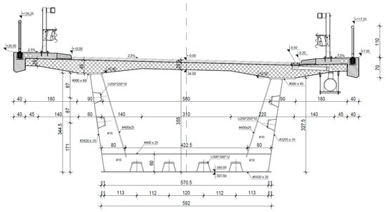
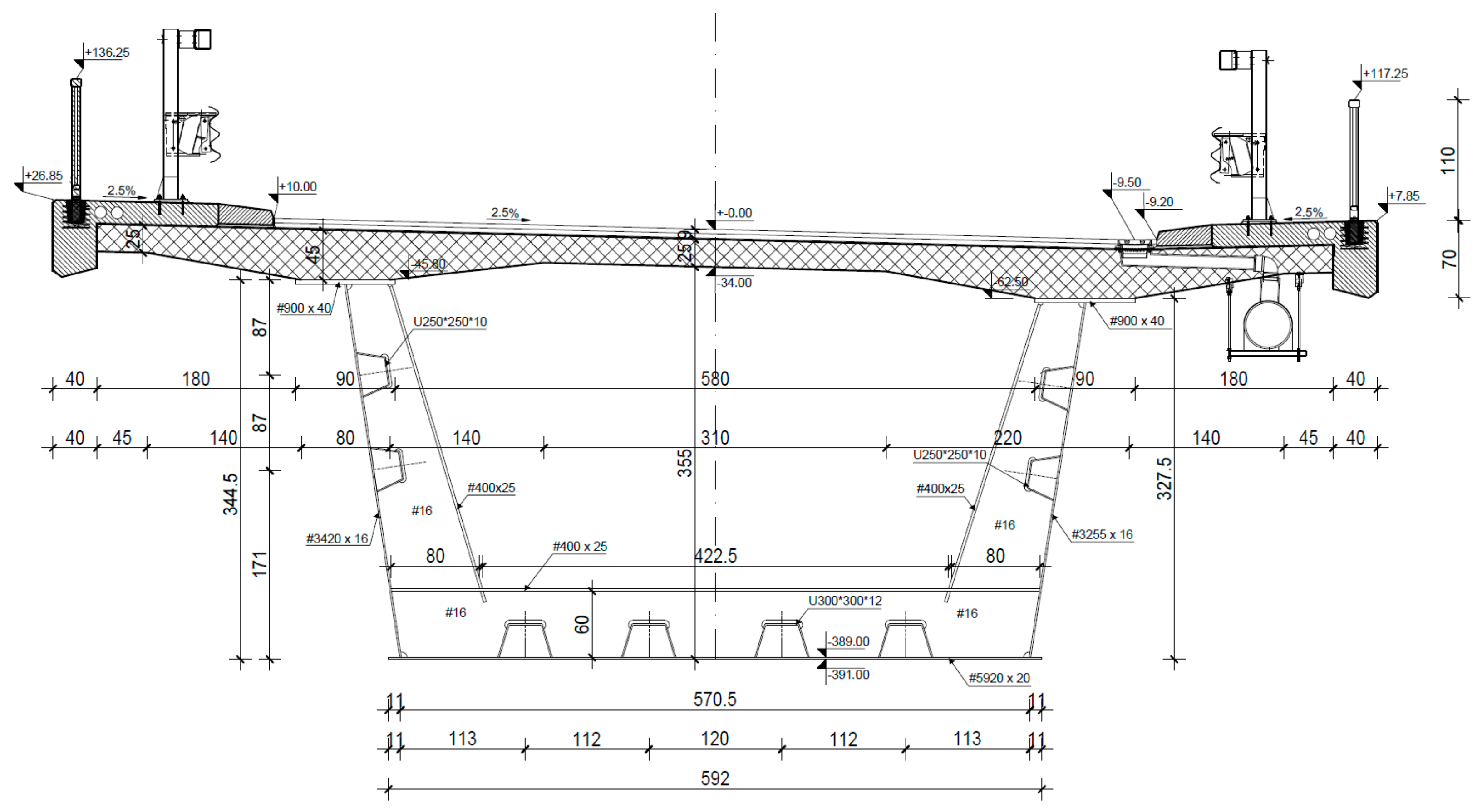
The steel box girder (Figure 2) consists of two separate upper flanges, each 900 mm (midspan) to 1100 mm (above supports) wide, a 592 cm wide bottom flange, and two webs with heights of 4420 mm and 326 cm, respectively. The thicknesses of the steel elements vary: bottom flanges, 20–40 mm; upper flanges, 40–80 mm; and webs, 16–25 mm. The webs and the bottom flanges are stiffened by 250 to 400 mm tall longitudinal trapezoidal stiffeners. The reinforced concrete deck slab is 1120 cm wide and has a variable thickness of 25 cm at the center of the cross-section and 45 cm above the upper flanges.
Figure 2.
Superstructure composite box girder cross-section.
The bridge superstructure is supported by two abutments and three reinforced concrete columns with constant rectangular hollow cross-sections. The bridge abutments are designed as massive reinforced concrete structures with parallel 50 cm thick wing walls monolithically connected to the 170 cm thick abutment wall and foundation. The column cross-section is 500 cm wide and 320 cm deep, with a wall thickness of 40 cm and local haunches at the corners. The columns are fixed into the foundations at their bottom and are extended at the top with column caps measuring 770 cm in length, 320 cm in width, and 160 cm in height. Both columns and abutments are founded on shallow 300 cm thick slabs. The column heights are about 21 m. All substructure elements are erected using C30/37 concrete.
2.2. Variants of Bearing Types and Layouts
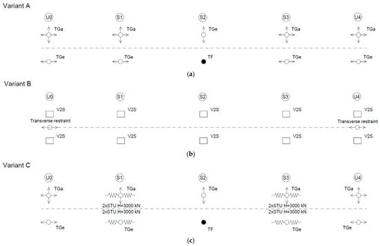
Three alternative seismic protection strategies, denoted as Variants A, B, and C (Figure 3), were considered to investigate the influence of different seismic response mechanisms on the structural behavior of the case study bridge. In Variant A (Figure 3a), seismic protection is based on energy dissipation through the limited ductile response of the central column. In the longitudinal direction, seismic forces are transferred through two longitudinally fixed bearings located at the central column. Consequently, the entire longitudinal seismic force is resisted by the central column, where seismic energy is dissipated through the partial formation of a flexural plastic hinge. A limited-ductility behavior was adopted for structural members. Accordingly, a behavior factor of q = 1.5 was adopted for the reinforced concrete columns. In the transverse direction, seismic forces are transferred through one transversely fixed bearing at each column and abutment.
Figure 3.
Bearing type and arrangement for 3 different variants of bridge seismic behavior: (a) central column fixed bearing; (b) seismic isolation; (c) Shock transmission units on S1 and S3.
In Variant B (Figure 3b), the bridge is designed using a seismic isolation system with a floating bearing arrangement. The superstructure is supported on the abutments and columns by means of elastomeric bearings (i.e., rubber isolators), thereby allowing increased horizontal movements and reducing the transmission of seismic forces to the substructure. Pairs of V2S bearings (Maurer) are installed at the columns and abutments, while additional transverse restraints are provided at the abutments.
Variant C (Figure 3c) incorporates longitudinal shock transmission units (STUs) installed at columns S1 and S3, in addition to a longitudinally fixed bearing at column S2 (as already present in Variant A). Under normal service conditions, the bearing arrangement is identical to that adopted in Variant A, comprising a pair of longitudinally fixed bearings at the central column and transversely fixed bearings at all columns and abutments. Under seismic loading, the STUs at columns S1 and S3 are activated, enabling the longitudinal seismic force to be distributed among all three columns. This arrangement differs from Variant A, in which the entire longitudinal seismic action is resisted by the central column alone.
3. Seismic Analysis, Modeling and Design
Modal response spectrum analysis (linear dynamic) was conducted for seismic action. This linear-elastic method is applicable to any bridge that does not exhibit a strongly nonlinear response (using damping or a nonlinear isolation system) [3]. It is accurate enough for estimation of internal forces in reinforced concrete members when using a design response spectrum, considering the limited ductile behavior of reinforced concrete columns. For a case study bridge, due to the high columns, the flexibility of the seismic force-resisting system results in long periods in both directions and thus relatively low response. Given these low seismic demands, designing the columns for ductile behavior is neither necessary nor cost-effective. Therefore, a limited-ductility design approach is adopted, with a behavior factor q not larger than 1.5. Calculation of seismic action is performed using a response spectrum for the location parameters given in Table 1.
Table 1.
Response spectrum seismic load parameters.
Elastic response spectrum (behavior factor q = 1) was used for calculation of bearing reactions and movements, and a design response spectrum with q = 1.5 was used for calculation of column bending moments. For shear design, a behavior factor of q = 1.0 was adopted [2]. According to Eurocode [2], for a seismically isolated bridge, the behavior factor is controlled to ensure that the substructure remains essentially elastic (essentially q = 1.0), protecting the substructure from damage. In this case study, for Variant B it was exceptionally adopted as q = 1.5 with provisions of a limited ductile overstrength design. Such a design decision was made to ensure a consistent comparison between all case-study bridge variants.
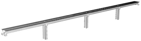
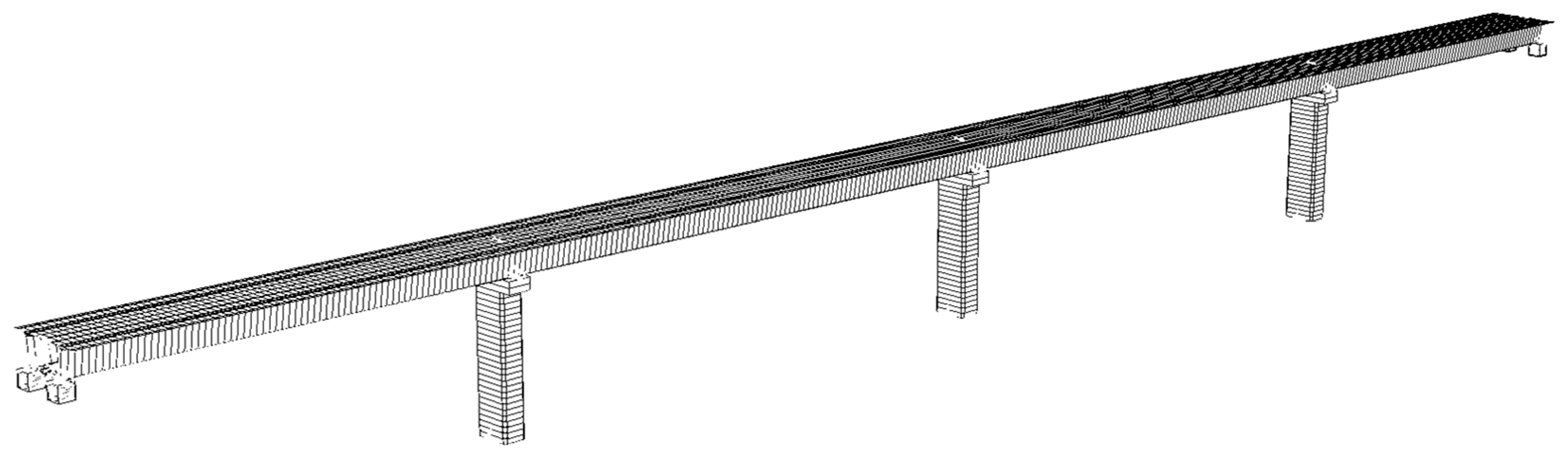
For each bridge variant (A, B and C described in Section 2.2), a numerical model was made (Figure 4). Superstructure and column elements were modeled using beam elements. Fixed bearings, STUs and seismic isolators were modeled using spring elements with corresponding stiffness. The stiffness of the seismic isolators was calculated according to their dimensions and product catalogue specifications as 2810 and 6100 kN/m for bearings above abutments and columns, respectively. These values were associated with horizontal spring elements in the model. STUs were modeled with springs whose large stiffness (106 kN/m) is activated only for earthquake loads. Damping was adopted as 5% across all bridge elements. Foundations and abutment walls were considered with fixed boundary conditions.
Figure 4.
3D FE model of a bridge.
Prior to seismic analysis, superstructure composite box section steel elements and concrete deck slab were designed according to ULS and SLS for all relevant loads (traffic load, temperature, wind). Column reinforcement area for each column wall was calculated directly by the software design module using ULS seismic combination internal forces for critical sections. Ductility requirements were satisfied additionally by calculation of confining reinforcement and transverse reinforcement hoop spacing for prevention of buckling of longitudinal bars.
4. Comparison of Results
4.1. Modal Shapes and Frequencies
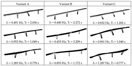
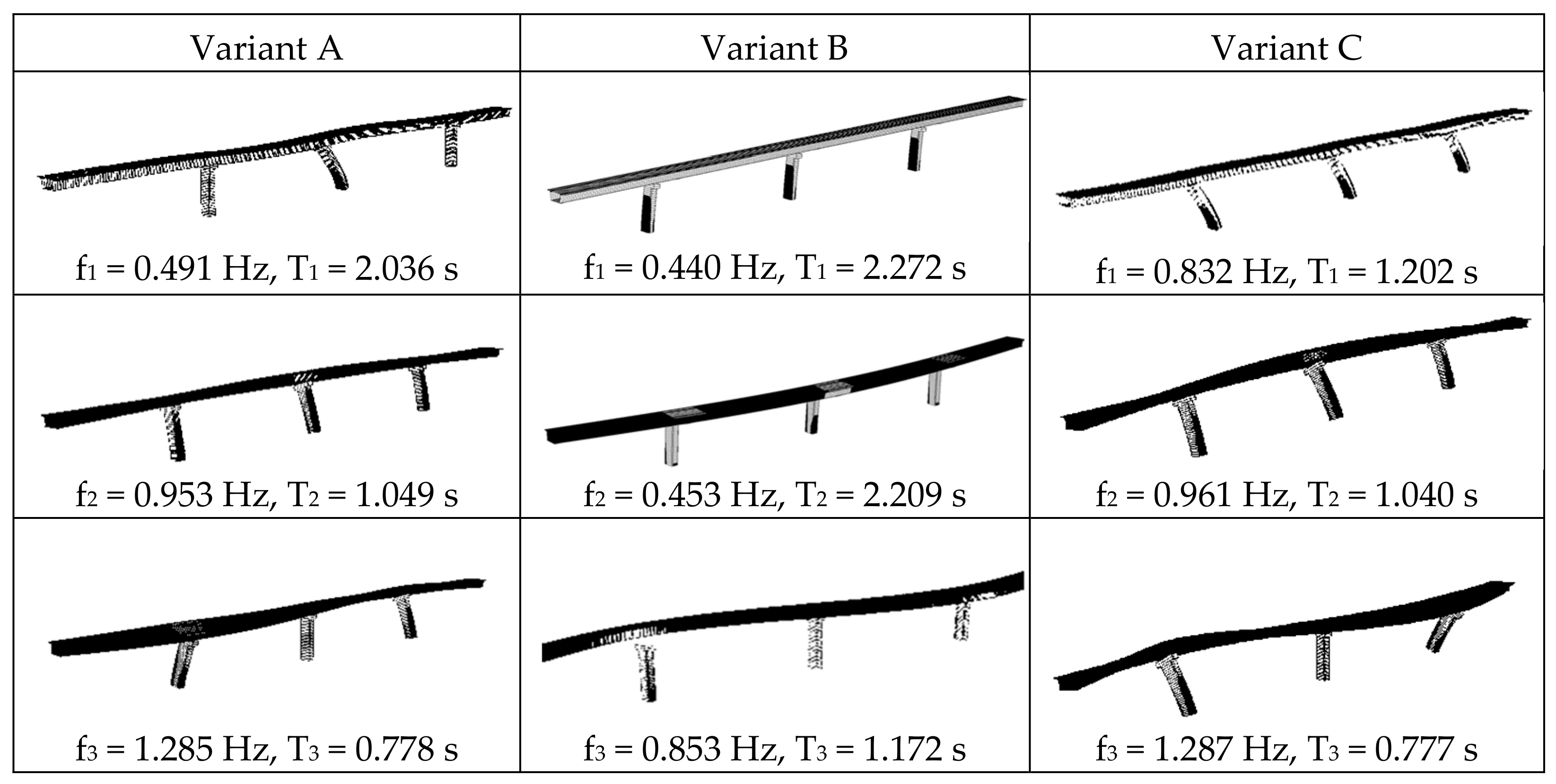
The modal analysis reveals a consistent sequence of vibration modes for all three seismic protection variants (Figure 5). In each case, the first mode is predominantly longitudinal, the second mode is transverse, the third mode is torsional, and the fourth mode is vertical. The subsequent modes are predominantly characterized by alternating torsional and vertical deformation patterns. Regarding the fundamental longitudinal mode, Variant B exhibits the most flexible structural response and, consequently, the longest fundamental period. This behavior results from the support of the superstructure on elastomeric isolation bearings. In contrast, Variant C represents the stiffest system, exhibiting the shortest fundamental period due to the activation of the shock transmission units (STUs) at the outer columns. The dynamic characteristics of Variant A lie between those of Variants B and C, although its fundamental period is considerably closer to that obtained for the seismically isolated system of Variant B. In Variant A, the entire longitudinal seismic action is resisted by the central column S2. Consequently, S2 is the only column that undergoes significant deformation in the longitudinal direction, and the corresponding fundamental period of T1 = 2.036 s is primarily governed by the dynamic response of this column. In Variant B, a substantial portion of the longitudinal deformation is concentrated within the elastomeric bearings, i.e., at the interface between the superstructure and substructure, while the deformation demands on all three columns are considerably smaller. The elastomeric bearings therefore partially decouple the motion of the superstructure from that of the substructure, reducing the seismic forces transferred to the columns. This response represents the intended effect of seismic isolation. Variant C exhibits the shortest longitudinal period because the activation of the STUs during a seismic event engages the outer columns in resisting the longitudinal seismic action. As a result, the seismic forces are distributed among all three columns, increasing the effective longitudinal stiffness of the structural system.
Figure 5.
Comparison of modal shapes and frequencies.
For the transverse vibration modes, the frequencies and periods obtained for Variants A and C differ only slightly and can therefore be considered practically identical. This similarity is attributed to the identical transverse bearing arrangement adopted in both variants. In Variant B, the elastomeric bearings have equal stiffness in the longitudinal and transverse directions, which is reflected in the similar periods and frequencies of the first two vibration modes. The transverse period is slightly shorter, due to the additional transverse restraints provided at the abutments, which marginally increase the overall transverse stiffness of the bridge. The third vibration mode is predominantly torsional for all three variants. In this mode, the superstructure and the outer columns exhibit rotational motion relative to the central column S2. Variants A and C show practically identical dynamic behavior in this mode. In Variant B, however, the deformation is again predominantly concentrated at the level of the elastomeric bearings, reflecting the increased flexibility introduced by the seismic isolation system.
4.2. Base Shear
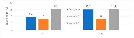
The total base shear represents the resultant reaction corresponding to the sum of all seismic inertia forces acting on the structure. For comparative purposes, base shear is commonly expressed as a percentage of the effective seismic weight of the bridge, i.e., the portion of the structural weight participating in the dynamic response (Figure 6). In the longitudinal direction (BSx), the highest base shear is obtained for Variant C, in which the longitudinal seismic forces are distributed among the columns through the activation of the shock transmission units (STUs). This is followed by Variant A, based on seismic energy dissipation through the response of the central column, while the lowest base shear is obtained for Variant B, incorporating seismic isolation. The higher seismic force observed in Variant C can be attributed to the substantial increase in the effective longitudinal stiffness of the structural system following activation of the STUs during seismic excitation. The resulting stiffer system attracts higher seismic forces. In contrast, the increased flexibility introduced by the elastomeric bearings in Variant B reduces the seismic forces transmitted from the superstructure to the substructure. Consequently, Variant B exhibits the lowest base shear among the three configurations, corresponding to approximately 8% of the effective seismic weight. In the transverse direction (BSy), the base shear values obtained for Variants A and C are nearly identical, with only negligible differences. This similarity results from the identical transverse bearing arrangement adopted in these two configurations. Variant B again exhibits a lower base shear due to the seismic isolation provided by the elastomeric bearings. Moreover, the base shear obtained for Variant B in the transverse direction is approximately equal to that in the longitudinal direction, which can be attributed to the equal horizontal stiffness of the elastomeric bearings in both principal directions. Overall, the base shear results clearly demonstrate the influence of the adopted seismic protection strategy on the global seismic response of the bridge. Increasing the effective stiffness of the structural system, as in Variant C, results in higher seismic force demand, whereas the increased flexibility and decoupling provided by the isolation system in Variant B led to a substantial reduction in the seismic forces transmitted to the substructure.
Figure 6.
Comparison of base shear.
4.3. Bearing Reactions
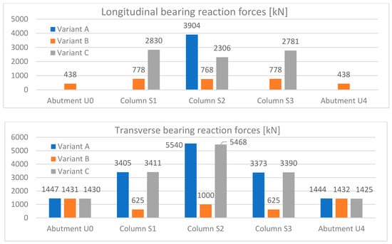
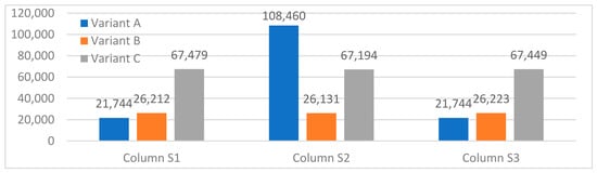
The highest longitudinal bearing reactions are obtained for Variant A, in which the entire longitudinal seismic force is transferred through the two longitudinally fixed bearings located at the central column (Figure 7). Each of these bearings carries a longitudinal reaction of 3904 kN (2 × 3904 kN total for column S2), whereas all other bearings are longitudinally movable. In Variant C, the longitudinal seismic force is transferred through the longitudinally fixed bearings at the central column and the shock transmission units (STUs) installed at the outer columns. Two pairs of STUs are provided at each outer column (where two STUs are active for each longitudinal direction). The seismic force transferred by each STU amounts to 2830 kN (2 × 2830 kN max total for outer column). This arrangement enables the longitudinal seismic action to be distributed among multiple columns rather than being concentrated exclusively at the central column, as is the case in Variant A. Variant B, characterized by elastomeric bearings installed at all columns and abutments, exhibits considerably lower longitudinal bearing reactions than Variants A and C. This reduction can be attributed to the decreased stiffness of the isolated structural system and to the distribution of the longitudinal seismic force among all support locations. Consequently, the concentration of seismic forces on individual bearings and substructure elements is significantly reduced. For Variants A and C, the distribution of transverse bearing reactions generally follows the transverse deformation pattern of the bridge. The magnitude of the reactions increases from the abutments towards the central column and subsequently decreases towards the opposite abutment. In Variant B, the distribution of transverse reactions differs due to the additional transverse restraints provided at the abutments, which modify the transfer and distribution of transverse seismic forces between the superstructure and substructure.
Figure 7.
Comparison of bearing reaction forces.
4.4. Column Bending Moments
For seismic action in the longitudinal direction, the maximum column bending moment is obtained at the central column of Variant A (Figure 8). In this configuration, the entire longitudinal seismic force is transferred to the central column through the two longitudinally fixed bearings. This concentration of seismic demand results in the highest bending moment among the three analyzed variants. The lowest column bending moments are obtained for Variant B, in which elastomeric bearings are installed at all support locations. The longitudinal seismic forces are therefore distributed among the abutments and all three columns. As a result, the bending moments at the bases of the three columns are approximately equal and considerably lower than those obtained for the other two variants. In Variant C, the activation of the shock transmission units (STUs) during longitudinal seismic excitation engages all three columns in resisting the seismic action. The bending moments are distributed approximately equally among the columns. However, due to the higher effective longitudinal stiffness of the structural system after activation of the STUs, the seismic forces transmitted to the substructure are greater than those in the isolated configuration. Accordingly, the column bending moments in Variant C are more than twice those obtained for Variant B, despite the relatively uniform distribution of seismic demand among the three columns.
Figure 8.
Comparison of bending moment for longitudinal seismic action [kNm].
For seismic excitation in the transverse direction (Figure 9), the maximum bending moments are obtained at the central column for all three variants. The bending moments calculated for Variants A and C are nearly identical, which is consistent with their identical bearing arrangements and, consequently, similar structural behavior in the transverse direction. In contrast, Variant B exhibits lower column bending moments than Variants A and C. This reduction is attributed to the seismic isolation effect of the elastomeric bearings, which increases the horizontal flexibility of the system and reduces the seismic forces transferred from the superstructure to the substructure.
Figure 9.
Comparison of bending moment for transverse seismic action [kNm].
4.5. Column Reinforcement
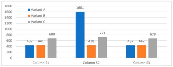
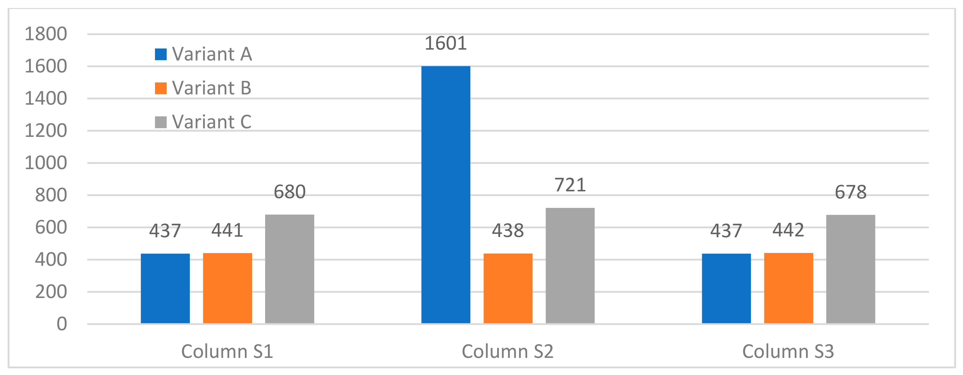
The required amount of longitudinal reinforcement in the columns varies considerably among the three variants, providing a clear indication of the influence of the adopted bearing arrangement and seismic protection strategy on the seismic demand imposed on the substructure (Figure 10). The highest reinforcement area is obtained for the central column of Variant A, which is consistent with the concentration of the entire longitudinal seismic action at this column. In contrast, the reinforcement requirements are distributed more uniformly among the columns in Variants B and C and are substantially lower than the demand at the central column of Variant A.
Figure 10.
Reinforcement of central column S2 for each of the variants.
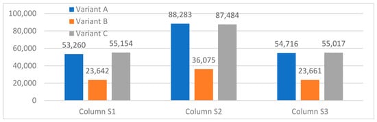
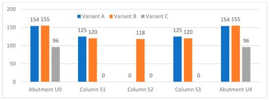
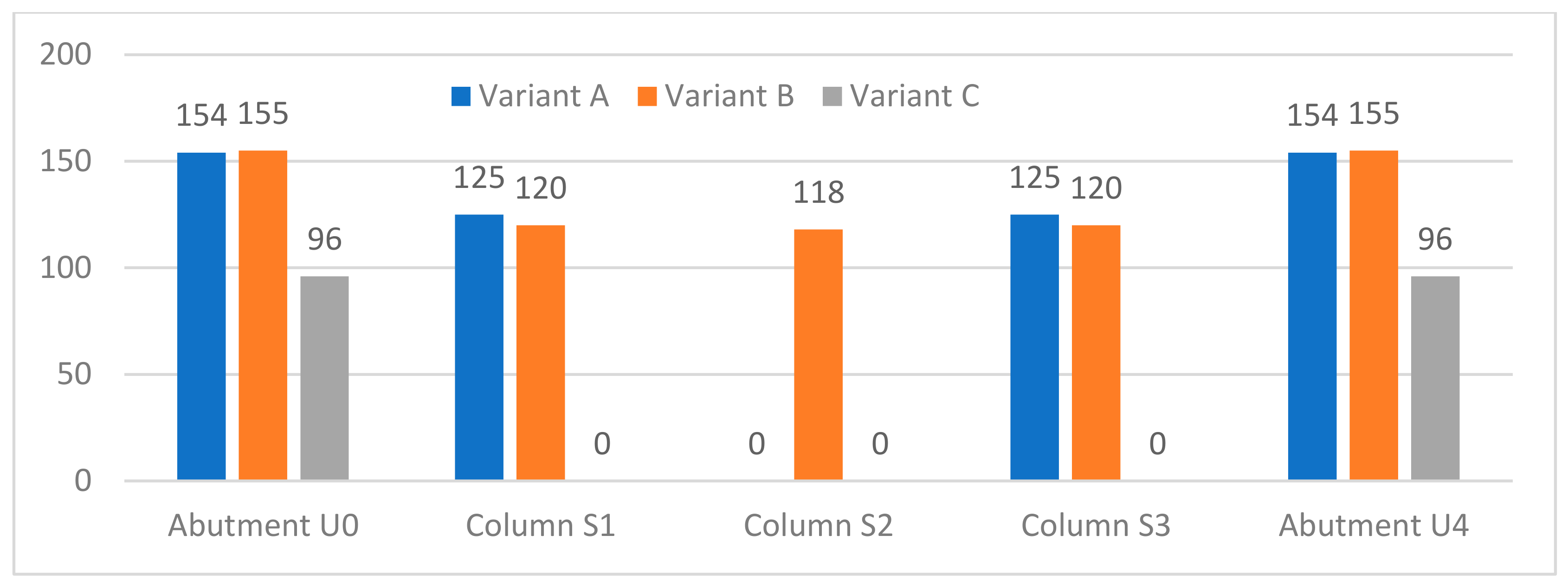
The beneficial effect of seismic isolation is particularly evident in Variant B. The total amount of longitudinal reinforcement required at the bases of all three columns in this variant is lower than the reinforcement required for the central column alone in Variant A (Figure 11). Furthermore, the outer columns of Variant A and all three columns of Variant B require only the minimum longitudinal reinforcement prescribed by the design provisions. This demonstrates the substantial reduction in seismic demand achieved by introducing elastomeric bearings and distributing the seismic forces among all support locations. For Variant C, the required longitudinal reinforcement is greater than that obtained for Variant B due to the higher seismic forces associated with the increased effective stiffness of the system following activation of the shock transmission units. Nevertheless, the reinforcement demand remains considerably lower and more uniformly distributed than in Variant A, resulting in more moderate reinforcement requirements across all three columns.
Figure 11.
Comparison of total column longitudinal reinforcement [cm2].
4.6. Longitudinal Displacements of the Bearings
Variant C, incorporating shock transmission units (STUs), exhibits the highest longitudinal stiffness and consequently the smallest longitudinal displacements of both the bearings and the superstructure among the three analyzed configurations (Figure 12). Although Variants A and B exhibit similar longitudinal bearing displacements at abutments and outer columns, the underlying deformation mechanisms differ significantly. In Variant A, the displacement is primarily caused by the longitudinal deformation of the central column, which alone resists the longitudinal seismic action. In contrast, the displacements in Variant B result from deformation of elastomeric bearings located at the interface between the superstructure and substructure at all column supports. Thus, in the isolated system, a significant portion of the relative displacement is due to deformation within the elastomeric bearings rather than the deformation of the column(s).
Figure 12.
Comparison of longitudinal displacements of the bearings [mm].
5. Conclusions
The selection of an appropriate seismic protection concept for bridges depends on a wide range of parameters, including the structural configuration of the bridge, site-specific seismic hazard and ground conditions, project-specific requirements defined by the client, and, in many cases, the cost of the selected seismic protection system. Consequently, the optimal seismic design strategy should be determined individually for each bridge, considering the structural system and its performance, constructability, reliability, and economic considerations. The bridge investigated in the preceding sections represents a structurally regular and symmetric configuration. Therefore, the comparative results obtained in this study should not be directly generalized to all bridge typologies. Bridges characterized by irregular structural configurations, such as unequal column heights, horizontal curvature, asymmetric support conditions, or other sources of structural irregularity, may exhibit substantially different dynamic and seismic responses. Nevertheless, the present analysis provides a useful basis for evaluating the fundamental differences between the considered seismic protection strategies.
Three different seismic response concepts were investigated: seismic energy dissipation (Variant A), seismic isolation (Variant B), and seismic force distribution using shock transmission units (Variant C). The comparison revealed significant differences in the dynamic characteristics of the bridge, the internal forces developed in the columns, and, ultimately, the required amount of column reinforcement.
In Variant A, the entire longitudinal seismic action is transferred to the central column. This results in a pronounced concentration of seismic demand and substantially higher internal forces in the central column, particularly bending moments and shear forces. Consequently, significantly larger amounts of both longitudinal and transverse reinforcement are required. An additional disadvantage of this configuration is the concentration of the longitudinal seismic load-resisting mechanism in a single column. Such a configuration provides limited redundancy in the longitudinal load path; therefore, severe damage or failure of the central column could significantly compromise the global stability and integrity of the bridge.
The seismically isolated configuration in Variant B exhibits more favorable dynamic and structural response characteristics. The use of elastomeric bearings decreased the horizontal stiffness of the system and partially decouples the dynamic response of the superstructure from that of the substructure. This results in lower seismic forces, reduced internal forces in the columns, and substantially lower reinforcement requirements. The reinforcement demand is approximately uniform among the three columns and considerably lower than in Variant A. Notably, the total reinforcement required for all three columns in Variant B is lower than that required for the central column alone in Variant A, clearly demonstrating the structural benefits of seismic isolation for the bridge considered in this study.
In Variant C, the longitudinal seismic action is distributed among the three columns through the activation of shock transmission units (STUs) at the outer columns. Their activation during seismic excitation increases the effective longitudinal stiffness and degree of restraint of the structural system. As a result, the longitudinal seismic forces are distributed more uniformly among the columns than in Variant A. However, the increased effective stiffness leads to higher seismic base shear compared with the other two variants. Consequently, although the internal forces and reinforcement requirements are more uniformly distributed among the columns in comparison to Variant A, their magnitudes are higher than those obtained for Variant B.
For the bridge considered in this study, the results indicate that seismic isolation and seismic force distribution using STUs provide a more favorable distribution of seismic demand than the energy-dissipation concept adopted in Variant A. Among the analyzed configurations, Variant B provides the greatest reduction in seismic forces, column bending moments, and reinforcement requirements. However, the applicability of elastomeric bearings may be constrained by their load-carrying capacity and deformation requirements, particularly for bridges with larger spans and higher vertical reactions. Therefore, their suitability must be verified for each specific bridge configuration.
Ultimately, the selection of a seismic protection system cannot be based solely on minimizing internal forces or reinforcement quantities. It requires a comprehensive assessment of the dynamic characteristics, seismic demand, structural redundancy, bearing capacity and displacement requirements, constructability, inspection and maintenance needs, and economic feasibility of the proposed system. The primary objective of seismic bridge design should be to ensure adequate structural safety while maintaining, to the extent required by the selected performance level, the post-earthquake functionality and accessibility of the bridge, particularly for structures of strategic importance.
Author Contributions
Conceptualization, L.T. and A.V.; methodology, A.V.; software, L.T. and A.V.; validation, A.V. and M.S.; formal analysis, L.T.; investigation, A.V.; resources, A.V. and M.S.; data curation, L.T.; writing—original draft preparation, A.V.; writing—review and editing, M.S.; visualization, L.T.; supervision, A.V. and M.S.; All authors have read and agreed to the published version of the manuscript.
Funding
This research received no external funding.
Institutional Review Board Statement
Not applicable.
Informed Consent Statement
Not applicable.
Data Availability Statement
The original contributions presented in this study are included in the article. Further inquiries can be directed to the corresponding author.
Conflicts of Interest
The authors declare no conflict of interest.
References
- MAURER Seismic Protection Systems. Technical Information and Dimensions; MAURER: München, Germany, 2001. [Google Scholar]
- EN 1998-2:2005/A2:2011; Eurocode 8: Design of Structures for Earthquake Resistance—Part 2: Bridges. Croatian Standard: Zagreb, Croatia, 2011.
- Kolias, B.; Fardis, M.N.; Pecker, A. Designers’ Guide to Eurocode 8: Design of Bridges for Earthquake Eesistance, EN 1998-2; ICE Publishing, Thomas Telford Ltd.: London, UK, 2012. [Google Scholar]



Disclaimer/Publisher’s Note: The statements, opinions and data contained in all publications are solely those of the individual author(s) and contributor(s) and not of MDPI and/or the editor(s). MDPI and/or the editor(s) disclaim responsibility for any injury to people or property resulting from any ideas, methods, instructions or products referred to in the content. |
© 2026 by the authors. Licensee MDPI, Basel, Switzerland. This article is an open access article distributed under the terms and conditions of the Creative Commons Attribution (CC BY) license.