


Abstract
The dependence of the energy gain and the power produced in an accelerator-driven subcritical reactor (ADSR) on the spatial distribution of power density, fuel type and beam intensity is studied. Four fuel types are analyzed: metallic, oxide, carbide and nitride. The analysis of the power and temperature evolution during different unprotected transients shows that the maximum power is limited by the fuel temperature during an unprotected beam overpower transient (UBOP). Metallic and oxide fuels can be used only in small power reactors. An ADSR with an electrical power of 750 MW can be achieved using nitride fuel.
1. Introduction
The first scheme of ADSRs was described by Bowman et al. in the early 1990s [1]. Initially, the ADSR concept was viewed mainly as a method to transmute nuclear waste. Two years later, Rubbia et al. demonstrated that a subcritical reactor based on the U-Th cycle and driven by an intense proton beam could achieve high energy gain, acting simultaneously as an energy source and a transmuter [2]. Subsequently, many programs and projects have been developed worldwide, all based on subcritical reactors driven by proton beams [3,4,5].
A new approach to ADSRs, focusing on their application as a safe and efficient energy source, was developed by our group [6,7]. A reactor core with an effective multiplication factor, keff, maintained in the range of 0.985–0.988 through control rod positioning ensures safe operation, prevents core damage or criticality during unprotected transients, and achieves an energy gain of G > 15. Active zones with larger dimensions are preferable, giving the possibility of obtaining the needed value of keff with lower enrichment, allowing for longer cycles and deeper actinide burnup (15–20% from the initial mass of actinides). One of the most interesting findings concerns the possibility of using light ion beams such as 7Li or 9Be with energies of 0.25–0.3 GeV/n instead of 1–1.5 GeV protons. Many factors related to the characteristics of the active zone and the particle beam that influence the efficiency of ADSRs have been studied in previous works. The present work examines the influence of fuel type and beam intensity on ADSR performance.
2. Beam Intensity
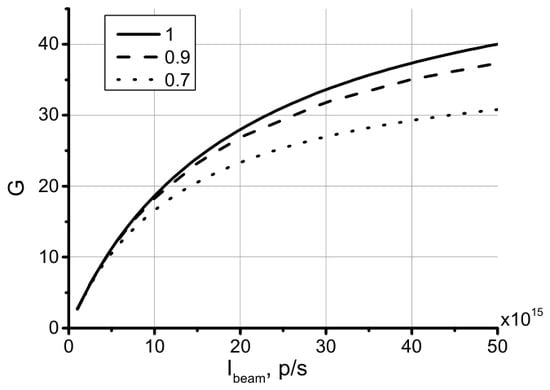
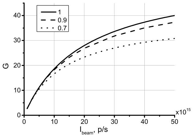
One of the most relevant factors in the efficiency of ADSRs, besides the type and the energy of the particle beam used to drive the subcritical reactor, is the beam intensity. ADSR requires a beam intensity above 1016 particles/second to operate efficiently. The influence of the beam intensity on the G value is exemplified in Figure 1. G is calculated as the ratio of the electrical power produced, Pprod, to the electrical power spent by the accelerator, Pspent, as detailed in [6]. The theoretical results presented in Figure 1 correspond to a 0.3 GeV/n 7Li beam, accelerated in a linear accelerator (LINAC), interacting with a Be converter and active zone with keff = 0.986. The energy released, obtained from simulation with the code Geant4, is 2.94 × 10⁵ MeV/p.
Figure 1.
Dependence of the energy gain, G, on the beam intensity and efficiency of power transmission in radio frequency (RF) cavities, ηb (subcritical core with keff = 0.986; 7Li beam with energy 0.3 GeV/n).
Pprod is calculated from the data on the energy released and the beam intensity, using a value of 0.4 for the conversion coefficient from thermal to electrical power. Pspent is a sum of two components: the power transmitted to the beam and the power spent to maintain the functioning of the accelerator, Pacc. Pacc is calculated using the method proposed in [6] by scaling data on the accelerator efficiency for a reference particle. The formulas previously used to calculate Pspent [6] assume that power is transmitted to the beam with 100% efficiency. Such an approach slightly overestimates G at high beam intensities. In this work, the formulas were modified by including the efficiency of the power transmission in radio frequency (RF) cavities, ηb. Using the scaling relation for Pacc given in [3], the power spent to accelerate the LINAC of a given particle with mass number A, atomic number Z, energy per nucleon E, and beam intensity Ib becomes:
The subscript 0 corresponds to the reference particle. As reference particle a 2 GeV proton with an accelerator efficiency of η0 = 0.2 was used. The dependence of G on beam intensity is given in Figure 1 for three values of ηb: 1, 0.9 (reached in superconducting RF cavities) and 0.7 (normal-conducting RF cavities). The use of superconducting cavities is more advantageous, especially for high-intensity beams. However, it must be underlined that the net electrical power obtained is almost the same due to the high values of G.
3. Fuel Type
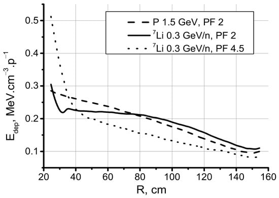
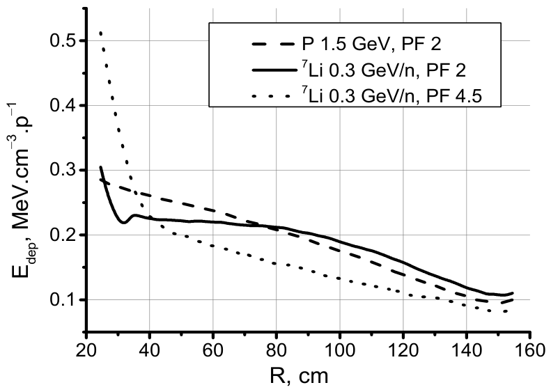
The thermo-physical properties of the fuels influence the maximum beam intensity and, consequently, the power that can be achieved in the reactor. The reactor power is limited by the evolution of the temperature in the hottest channel. The peak factor (PF) of the power distribution in an ADSR is higher than in a fast reactor (FR). A beam of protons interacting in a core with a lead–bismuth eutectic (LBE) converter and uniform enrichment yields a power distribution with PF~2. The power distribution obtained with ion beams and a Be converter strongly peaks near the converter in the core, with uniform enrichment. In this situation, the distribution can be modeled using a nonuniform distribution of the enrichment. One must start with low enrichment in proximity to the converter, increasing the level until the bulk value reaches 2–5 layers of fuel rods. In this manner, configurations with different PFs can be realized, as is shown in Figure 2. It should be noted that lowering the PF while maintaining the same keff diminishes the contribution of the neutrons with high importance factors to the total number of fissions and is conducive to lower values for the energy released. In the core with uniform enrichment, a beam of 7Li with an energy of 0.25 GeV/n generates the same energy released as 1.5 GeV protons [6], but in a core with PF~2, it is necessary to increase the energy of 7Li to 0.3 GeV/n. The values of the energy released corresponding to the distributions presented in Figure 2 are given in Table 1.
Figure 2.
Radial distribution of the energy density in the central part of the core with keff = 0.986, irradiated with 0.3 GeV/n 7Li and a 1.5 GeV proton.
Table 1.
Dependence of the energy released Edep on the PF in the core with keff = 0.986.
The evolution of the temperature in the hottest channel during various unprotected transients must be kept within safe limits. From the point of view of the fuel, the maximum centerline temperature must remain at least 100 K below the melting temperature of the fuel. Lead- or LBE-cooled FRs and ADSRs have high stability regarding transients [8,9,10]. All feedback reactivity coefficients can be made negative with a proper design, and natural convection can ensure enough heat removal to limit any increase in power and temperature and avoid fuel and clad melting during unprotected accidents. A higher pitch-to-diameter ratio can be utilized in ADSRs compared to FRs, accommodating higher power densities. The simulations shown in the present work use the following geometry of the fuel pins: a fuel pellet radius of 4.5 mm, a helium-filled gap thickness of 0.15 mm, a ferritic martensitic cladding thickness of 0.6 mm, and a pitch-to-diameter ratio of 2. The length of the active zone is 160 cm. The fuel rods surround the converter, and the entire assembly is immersed in an LBE cylinder with a radius of 5 m and a length of 8 m. Different U-Pu fuels are analyzed: metallic, oxide, carbide and nitride. In each case, the enrichment is adjusted to achieve keff = 0.986. The power distribution has PF = 2. The coolant velocity is 2 m/s.
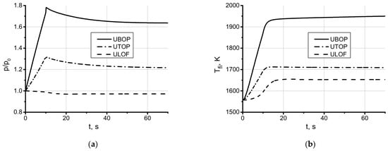
Evolution during various transients was analyzed. The evolution of the reactor power during an unprotected loss of flow (ULOF), unprotected overpower (UTOP) and unprotected beam overpower (UBOP) transients is shown in Figure 3a. The corresponding evolution of the maximum centerline temperature is given in Figure 3b. The results are obtained in a core with nitride fuel, irradiated with a 0.3 GeV/n 7Li beam with an intensity of 2 × 10¹⁶ p/s. The transients developed over a period of 10 s. An insertion of 400 pcm was assumed during UTOP and a twofold increase in the beam intensity in UBOP. The method to calculate the power and temperature distribution is described in [6].
Figure 3.
Power evolution (a) and the evolution of the maximum centerline temperature of the fuel (b) in a core during ULOF, UTOP and UBOP transients with keff = 0.986.
The steady-state distribution of the energy released and the values of the reactivity coefficients (the Doppler reactivity coefficient of the fuel αD = −0.82 pcm/K, the reactivity coefficient of the coolant αc = −0.12 pcm/K, the radial reactivity coefficient αR = −0.71 pcm/K, and the axial reactivity coefficient αA = −0.24 pcm/K) were obtained from simulation with Geant4. The power at time t obtained through simulation, P0(t), is corrected taking into account the reactivity feedback:
where ρ0 is the reactivity in steady-state, and ρ(t) is the corrected reactivity taking into account the difference between the mean temperature of the fuel (coolant) Tf(Tc) at time t and the mean temperature in steady-state Tf0(Tc0):
ρ(t) = ρ0 + (αD + αA)(Tf(t) − Tf0) + (αc + αR)(Tc(t) − Tc0)
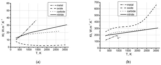
The temperature distribution is calculated using the control volume approach for the discretization of the heat transfer equations and a fully implicit scheme. The parameterizations for the thermo-physical properties of the T91 steel, LBE, the heat exchange coefficient of the gap, and the heat exchange coefficient at the surface clad-coolant are those given in [6]. The heat capacity and thermal conductivity of the fuels used in the calculation are shown in Figure 4. As shown in Figure 3, the most severe transient, with the highest fuel temperature limiting the beam intensity, is UBOP.
Figure 4.
Thermal conductivity (a) and specific heat capacity (b) for metallic, oxide, carbide and nitride fuels.
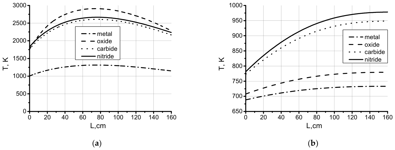
For each investigated fuel, the temperature evolution during UBOP was calculated for different beam intensities, and the maximum allowed beam intensity was determined. The results are given in Table 2. The temperature distributions realized in the hottest channel in the new steady state reached in the transient, corresponding to the beam intensities from Table 2, are shown in Figure 5. The distribution of the centerline fuel temperature is presented in Figure 5a. It can be seen that the condition to keep the maximum value within 100 K below the melting temperature of the fuel is fulfilled. The safety margin is higher for nitride fuel. In the case of nitride fuel, the maximum power is limited by the condition to keep the fuel temperature below 2300 K during the normal operation of the reactor in order to avoid fuel decomposition. The distribution of the outer temperature of the clad is shown in Figure 5b. In this case, the condition for safe operation is to maintain the temperature at the clad-coolant surface below 1023 K during the transient in order to avoid clad damage. This condition is fulfilled for all fuels.
Table 2.
Maximum beam intensity Ibmax, electrical power Pel, and G for different fuels and values of ηb.
Figure 5.
Distribution of the centerline temperature of the fuel (a) and of the outer clad temperature (b) in the new steady state reached during UBOP.
Metallic fuel, in spite of its highest thermal conductivity, has the lowest melting temperature (1390 K) and can accommodate the lowest power density. The maximum electrical power obtained in the ADSR with metallic fuel is ~150 MW. Oxide fuel has a high melting temperature (3023 K) but low thermal conductivity, and the maximum power is below 300 MW. Metallic and oxide fuels are suitable for small-power ADSRs. Carbide and nitride fuels can be used for medium-power reactors, with electrical power of 650–750 MW. The highest electrical power can be reached with nitride fuel.
4. Conclusions
These results contribute to the ongoing effort to design ADSR concepts that combine safety with efficient energy production.
The efficiency of ADSR depends strongly on the beam intensity. The energy gain G increases with beam intensity. Due to the high G values, the net electrical power produced is less sensitive to the use of superconducting or normal RF cavities.
The maximum electrical power produced depends on the peak factor of the power density and on the fuel type. It is limited by the evolution of the fuel temperature in the hottest channel during the UBOP transient.
Metallic and oxide fuels can be used only in small power ADSR (below 300 MWe). Carbide and nitride fuels are preferable, allowing for the building of reactors with electrical power outputs of 670–750 MWe. The best results are obtained with nitride fuel.
Author Contributions
Conceptualization, M.P.; methodology, M.P. and T.N.T.; software, M.P. and T.N.T. and V.M.J.; validation, M.P. and O.V.B.; formal analysis, M.P. and O.V.B.; writing, M.P. and T.N.T. All authors have read and agreed to the published version of the manuscript.
Funding
This research was funded by a grant from the Plenipotentiary Representative of the Vietnam Government at JINR, Dubna, JINR order 462/12.05.2026, p. 1.
Institutional Review Board Statement
Not applicable.
Informed Consent Statement
Not applicable.
Data Availability Statement
The original contributions presented in this study are included in the article. Further inquiries can be directed to the corresponding author.
Conflicts of Interest
The authors declare no conflicts of interest.
References
- Bowman, C.D.; Arthur, E.D.; Lisowski, P.W.; Lawrence, G.P.; Jensen, R.G.; Anderson, J.L.; Blind, B.; Cappiello, M.; Davidson, J.W.; England, T.R.; et al. Nuclear energy generation and waste transmutation using accelerator driven intense thermal neutron source. Nucl. Instr. Meth. A 1992, 320, 336–367. [Google Scholar] [CrossRef] [Scilit]
- Carminati, F.; Klapisch, R.; Revol, I.P.; Roche, C.; Rubio, J.A.; Rubbia, C. An Energy Amplifier for Cleaner and Inexhaustible Nuclear Energy Production Driven by a Particle Beam Accelerator. CERN/AT/93-47 1993. Available online: https://cds.cern.ch/record/256520/files/at-93-047.pdf?version=1 (accessed on 1 October 2026).
- Fiori, F.; Zhou, Z. A study on the Chinese nuclear energy options and the role of ADS reactor in the Chinese nuclear expansion. Prog. Nucl. Energy 2016, 91, 159–169. [Google Scholar] [CrossRef] [Scilit]
- Toshinobu, S. Research activities for accelerator-driven transmutation system at JAERI. Prog. Nucl. Energy 2005, 47, 314–326. [Google Scholar] [CrossRef] [Scilit]
- Zhao, Z.; Chen, Z.; Chen, H. Preliminary optimization of proton energy and target for lead-bismuth eutectic target of a demonstration ADS. Prog. Nucl. Energy 2014, 71, 117–121. [Google Scholar] [CrossRef] [Scilit]
- Paraipan, M.; Javadova, V.M.; Tyutyunnikov, S.I. Influence of Particle Beam and Accelerator Type on ADS Efficiency. Nucl. Sci. Eng. 2024, 198, 109–120. [Google Scholar] [CrossRef] [Scilit]
- Paraipan, M.; Abduvaliev, A.; Balabekyan, A.; Belov, O.V.; Ergashev, F.H.; Javadova, V.M.; Korneev, S.V.; Kostov, L.K.; Khushvaktov, J.H.; Kulikov, S.A.; et al. Extended lead target for studying the perspectives of accelerator driven subcritical reactor. Nucl. Sci. Eng. 2025, 200, 1490–1502. [Google Scholar] [CrossRef] [Scilit]
- Hashim, M.; Cao, L.; Zhou, S.; Ma, R.; Shao, Y.; Chen, R. SPARK – NC: A lead-bismuth-cooled small modular fast reactor with natural circulation and load following capabilities. Energies 2020, 13, 5410. [Google Scholar] [CrossRef] [Scilit]
- Suzuki, T.; Chen, X.-N.; Rineiski, A.; Maschek, W. Transient analyses for accelerator driven system PDS – XADS using the extended SIMMER – III code. Nucl. Eng. Des. 2005, 235, 2594–2611. [Google Scholar] [CrossRef] [Scilit]
- Li, R.; Chen, X.-N.; Matzerath Boccaccini, C.; Rineiski, A.; Maschek, A. Study on severe accident scenarios: Pin failure possibility of MYRRHA FASTEF critical core. Energy Proc. 2015, 71, 14–21. [Google Scholar] [CrossRef] [Scilit]

Disclaimer/Publisher’s Note: The statements, opinions and data contained in all publications are solely those of the individual author(s) and contributor(s) and not of MDPI and/or the editor(s). MDPI and/or the editor(s) disclaim responsibility for any injury to people or property resulting from any ideas, methods, instructions or products referred to in the content. |
© 2026 by the authors. Licensee MDPI, Basel, Switzerland. This article is an open access article distributed under the terms and conditions of the Creative Commons Attribution (CC BY) license.