


Abstract
This paper presents the implementation and field evaluation of a short-range frequency-modulated continuous-wave (FMCW) radar based on an ADALM-PLUTO software-defined radio, a 23 dBi dual-polarized antenna, and MATLAB processing. A 56 MHz triangular sweep centered at 5.5 GHz was transmitted continuously. Because transmission and frame acquisition were asynchronous, a two-period reference and cross-correlation were used only to locate the waveform boundary before full-period dechirping, Hann windowing, and a 131,072-point FFT. The receiver used manual gain of 57 dB. For single stationary vehicles from 10 to 30 m, the retained estimates yielded an MAE of 0.48 m, an RMSE of 0.52 m, and a mean absolute percentage error of 2.53%. Two-vehicle tests produced one dominant response at a common nominal range and distinct peaks at nominal separations of 10 and 15 m. These results support the practical suitability of the proposed SDR-based architecture for short-range distance estimation and multi-target detection under the evaluated conditions. Future studies will consider target separations closer to the theoretical resolution limit, repeated measurements, and controlled target positioning to provide a more detailed characterization of the system performance.
1. Introduction
Frequency-modulated continuous-wave (FMCW) radar estimates target range from the beat frequency produced by mixing a transmitted linear frequency sweep with its delayed echo. For a stationary target, beat frequency is proportional to round-trip delay, whereas the available sweep bandwidth establishes the fundamental ability to separate adjacent echoes [1,2,3]. FMCW architecture is attractive for short-range sensing because it operates continuously at modest transmit power and move much of the ranging task into digital signal processing.
Software-defined radio (SDR) platforms provide a flexible way to implement and modify such processing without redesigning dedicated RF hardware. The ADALM-PLUTO integrates a full-duplex transceiver with host-based control and MATLAB support, enabling rapid changes in center frequency, sampling rate, bandwidth, and gain [4,5,6]. This work therefore focuses on compact SDR-based FMCW implementation for stationary-target range estimation rather than Doppler or velocity processing.
The contributions of this study are as follows: (i) the implementation of a 56 MHz triangular FMCW waveform at 5.5 GHz; (ii) explicit synchronization of asynchronous TX/RX framing by cross-correlation; (iii) dechirp and zero-padded FFT range processing with a documented leakage cutoff and manual peak-selection procedure; and (iv) outdoor tests with one and two vehicles. The analysis distinguishes single-target localization accuracy from two-target range resolution and limits the conclusions to what is supported by the available field measurements.
2. Materials and Methods
2.1. Hardware and Triangular FMCW Waveform
The experimental platform used MATLAB R2026a, an ADALM-PLUTO SDR with firmware v0.39, and an Altelix AD5G23M2 dual-polarized parabolic antenna. The antenna provides 23 dBi nominal gain over 4.9–6.4 GHz; the manufacturer specifies approximately 9.8° horizontal and 7.5° vertical half-power beamwidths and at least 28 dB isolation between polarization ports [7]. Horizontal polarization was used for transmission and vertical polarization for reception. These beamwidth and polarization characteristics are relevant when interpreting off-axis two-vehicle measurements [8]. Radar propagation and extended-target scattering were interpreted using standard radar-range and short-range radar considerations [9,10].
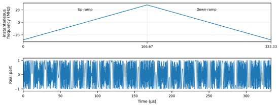
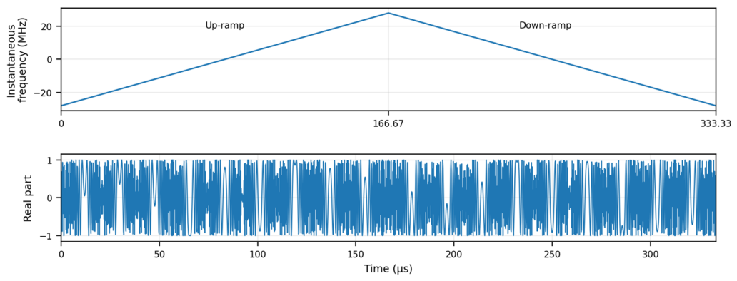
The baseband sampling rate was 60 MS/s. A 2 MHz guard interval was retained at both Nyquist edges, so the MATLAB waveform swept from −28 to +28 MHz, giving B = 56 MHz. Figure 1 shows the MATLAB-equivalent instantaneous-frequency pattern and the real component of the complex transmitted chirp. One complete triangular period contained 20,000 complex samples and lasted for Ttri = 333.33 µs; each linear ramp therefore contained 10,000 samples and lasted for Tr = 166.67 µs. Equation (1) defines the magnitude of the ramp slope.
S = B/Tr = 2B/Ttri = 3.36 × 10¹¹ Hz/s
Figure 1.
MATLAB-generated triangular FMCW waveform used in the experiment: instantaneous frequency and real component of one complex baseband period.
With this bandwidth, the theoretical range resolution follows Equation (2). This is a two-target separation limit and should not be interpreted as the minimum error attainable when localizing one isolated spectral peak.
ΔR = c/(2B) = 2.68 m
Table 1 summarizes the hardware, waveform, gain, and FFT parameters used in the retained measurements. The receiver gain was fixed manually at 57 dB for the field tests, as documented in the implementation code, so automatic gain control was not used.
Table 1.
Main hardware, waveform, and processing parameters.
2.2. Synchronization, Dechirp, and Spectral Processing
The transmitted 20,000-sample vector was stored in the SDR buffer and repeated continuously. The receiver acquired 40,000 samples, corresponding to two triangular periods, because the transmit-repeat operation and host-side frame acquisition did not start synchronously. A local two-period copy of the transmitted waveform was used as a correlation reference. The MATLAB implementation used the unnormalized complex cross-correlation in Equation (3), retained only non-negative lags, and selected the lag with maximum correlation magnitude. The candidate start index was constrained to the first-period interval so that a complete 20,000-sample receive period could be extracted.
ryx[k] = Σ yr[n + k] x*[n], ksync = arg max |ryx[k]|
k ≥ 0
The correlation peak is used only to identify the waveform/frame boundary; target range is not estimated from correlation delay. The available measurements do not isolate whether the dominant synchronization feature is produced mainly by direct TX-RX leakage, the repeated transmitted waveform, target echoes, or their coherent combination, so no stronger attribution is made. This limitation is explicitly separated from the subsequent beat-frequency ranging stage.
After synchronization, the full 20,000-sample triangular period was dechirped according to Equation (4). The implementation does not split and average the two ramps. Instead, the full-period dechirped signal contains beat components of opposite sign over the up- and down-ramp halves for a stationary target; the FFT is applied to the complete period and only the positive-frequency half spectrum is retained. Thus, under the implemented conjugation convention, the positive-sign ramp contribution is used for range readout, while the opposite-sign contribution is discarded. This is adequate for the stationary ranging experiments but does not exploit the two ramps for Doppler separation.
yb[n] = yr[n] · yt*[n].
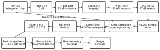
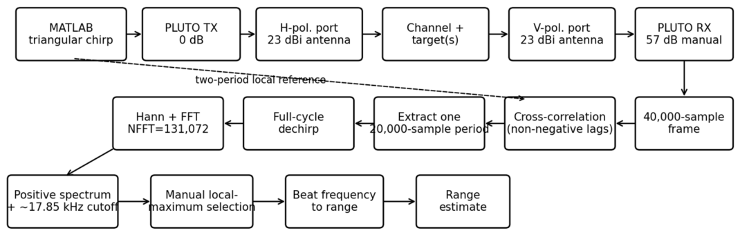
A Hann window was applied before the FFT. The implementation uses NFFT = 2(nextpow2(20,000) + 2) = 131,072, corresponding to a zero-padding factor of 6.55 relative to the 20,000-sample full period and an FFT spacing of 457.76 Hz. Standard discrete-time spectral analysis, windowing, and single-tone peak-localization considerations are described in [11,12,13]. Zero padding therefore gives a displayed range-grid spacing of approximately 0.204 m, but it does not improve the physical 2.68 m range resolution. Figure 2 summarizes the complete RF and processing chain.
Figure 2.
RF and digital-processing architecture implemented in MATLAB and ADALM-PLUTO, including asynchronous-frame synchronization, full-period dechirp, FFT processing, leakage rejection, and range readout.
The target-search region excluded the first 40 displayed bins. With the frequency axis used in the MATLAB code, the corresponding threshold is approximately 17.85 kHz, or 7.96 m after applying Equation (5). The cutoff was selected empirically from preliminary spectra to reject the persistent near-DC coupling region and associated sidelobes; it is therefore an implementation-specific processing limit, not a fundamental FMCW minimum range. Dedicated leakage-cancellation methods could reduce this limitation [14].
R = c|fb|/(2S) = c|fb|Ttri/(4B).
The reported target ranges were not produced by an automated CFAR or findpeaks routine. They were retained from the local maxima displayed in the MATLAB range spectrum using data-tip/visual peak selection. Consequently, peak association is manual and is treated as a methodological limitation. The distinction between spectral resolution and isolated-peak localization is important because sub-resolution localization of one dominant tone is possible without resolving two adjacent targets [15]. Separate-ramp FMCW/SDR processing for moving targets has been demonstrated elsewhere [16,17], but velocity estimation is outside the scope of this stationary-target study.
2.3. Experimental Procedure
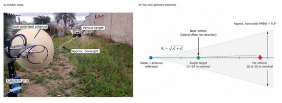
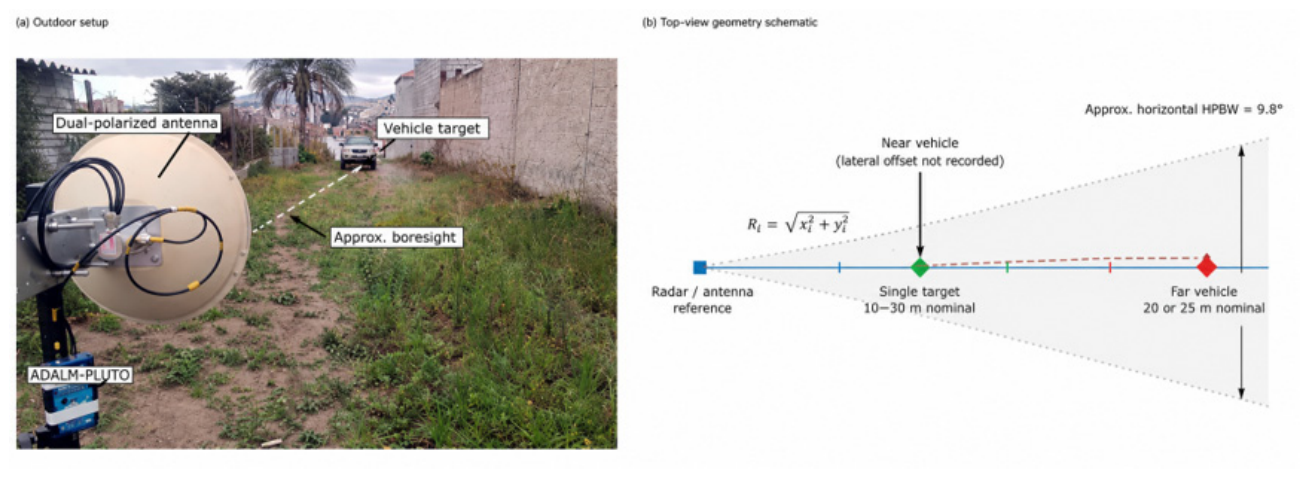
Outdoor measurements were performed along a path bordered by grass, concrete walls, vegetation, and metallic objects. Single-vehicle tests used nominal positions of 10, 15, 20, and 30 m along the antenna boresight. Two-vehicle tests used nominal longitudinal configurations of 10/10, 10/20, and 10/25 m. The near vehicle was moved laterally in the two-target configurations to preserve visibility of the farther vehicle. Figure 3a shows the outdoor setup and Figure 3b summarizes the measurement geometry and approximate horizontal beamwidth.
Figure 3.
Experimental arrangement: (a) annotated outdoor setup; (b) schematic top view showing antenna boresight, approximate horizontal HPBW, nominal longitudinal target positions, and the unrecorded lateral offset of the near vehicle.
The underlying project record identifies the distances as physically measured nominal positions relative to the antenna, but it does not retain the measurement instrument uncertainty, the exact vehicle reference surface, antenna height, or the lateral offsets used in the two-target tests. Therefore, the values in the result tables are reported as nominal reference distances rather than calibrated slant ranges. Because a vehicle is an extended radar target, the dominant scattering center can also differ from the physical point used for placement.
Only one retained estimate was available for each configuration. Accordingly, MAE and RMSE summarize agreement across the tested reference distances; they do not quantify repeated-measurement variability. Standard deviation, confidence intervals, repeatability, and measurement stability are therefore not claimed.
3. Results
3.1. Single-Target Measurements
Table 2 reports the single-vehicle results. The retained estimates were 10.21, 14.50, 19.60, and 30.80 m for nominal positions of 10, 15, 20, and 30 m, respectively. The maximum absolute error was 0.80 m and all related errors were below 3.5%. Across the four nominal ranges, MAE was 0.48 m, RMSE was 0.52 m, and mean absolute percentage error was 2.53%. Because the RX gain remained fixed at 57 dB, changes in spectral amplitude were not caused by AGC; nevertheless, propagation loss, the vehicle scattering response, and multipath all influence the received magnitude.
Table 2.
Retained single-target range estimates and errors.
3.2. Two-Target Measurements
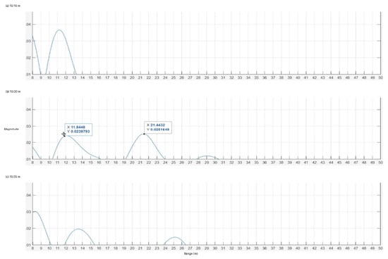
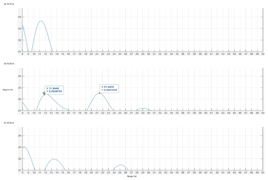
Table 3 summarizes the two-vehicle measurements. At the common nominal 10/10 m configuration, one dominant response was observed at 11.20 m. For the 10/20 m configuration, two local maxima were retained at 11.84 and 21.44 m; for 10/25 m, the retained maxima were 13.60 and 25.20 m. Figure 4 shows the corresponding MATLAB range-magnitude profiles and provides direct evidence of the merged common-range response and the separated peaks at the two wider spacings.
Table 3.
Retained two-target range estimates. Reference values are nominal longitudinal positions.
Figure 4.
Measured MATLAB range-magnitude profiles for (a) 10/10 m, (b) 10/20 m, and (c) 10/25 m nominal configurations. The plots preserve the original acquisition magnitude scale; the common-range case shows one dominant lobe, whereas the other two configurations show two main lobes.
These tests do not directly validate a 2.68 m experimental resolution threshold because the non-zero tested separations, 10 and 15 m, are much larger than theoretical value. The observations are therefore only qualitatively consistent with bandwidth-limited resolution. A quantitative resolution experiment would require controlled target separations near approximately 2–4 m.
4. Discussion
The single-target errors are smaller than the 2.68 m theoretical range resolution without contradiction: resolution describes separation of adjacent echoes, whereas localization describes the position assigned to one isolated spectral maximum. The 0.204 m zero-padded display grid improves spectral sampling for peak readout but does not create additional physical bandwidth. Similar distinctions between resolution and high-accuracy FMCW ranging have been addressed in high-precision FMCW work [15].
The 13.60 m estimate for the nominally 10 m near vehicle in the 10/25 m test requires cautious interpretation. Because the lateral offset and calibrated slant range were not recorded, the 3.60 m difference cannot be attributed primarily to lateral displacement. A geometric change from 10 to 13.6 m by lateral offset alone would require an offset of about 9.2 m. More plausible contributors include a changed dominant scattering center on the extended vehicle, manual peak association, off-axis antenna response, and multipath from nearby reflectors. Clutter and multipath are well-known limitations in practical radar scenes [18].
The present implementation is intentionally restricted to stationary targets. FMCW processing that separately uses increasing and decreasing ramps can support range–Doppler separation. The same SDR-based field-measurement philosophy has also been used for cluttered radar experiments, direction finding, and previous prototype radar work [18,19,20]. These references support the implementation context but do not replace the limitations of the present dataset.
Antenna coverage also limits the interpretation of the two-target amplitudes. Using the 9.8° horizontal HPBW reported by the antenna manufacturer, the approximate −3 dB beam width is 1.71 m at 10 m, 3.43 m at 20 m, and 4.29 m at 25 m. Because the lateral offsets were not recorded, it cannot be demonstrated that both vehicles remained inside the −3 dB main beam in every configuration. Off-axis attenuation may therefore have changed the apparent peak magnitudes and detectability. The fixed 57 dB manual RX gain removes AGC as a source of amplitude variation between tests, but the measurements still cannot be used as a calibrated validation of propagation loss because vehicle radar cross-section, aspect angle, scattering center, and multipath varied with geometry [7,8,9].
The principal limitations are the 56 MHz instantaneous bandwidth, the empirical near-DC cutoff, manual peak selection, a single retained acquisition per configuration, and incomplete geometric metrology for the two-target tests. These constraints are now reflected explicitly in the claims rather than being interpreted as evidence of repeatability or direct experimental verification of the theoretical resolution limit.
5. Conclusions
A short-range FMCW radar was implemented with an ADALM-PLUTO SDR, a dual-polarized 23 dBi antenna, and MATLAB processing. The 56 MHz triangular waveform yields a theoretical bandwidth-limited range resolution of 2.68 m. Cross-correlation was used only to determine the asynchronous waveform boundary, after which one full triangular period was dechirped, Hann-windowed, transformed with a 131,072-point FFT, and converted from beat frequency to range.
For single stationary vehicles from 10 to 30 m, the retained estimates yielded an MAE of 0.48 m, an RMSE of 0.52 m, and a mean absolute percentage error of 2.53%. These statistics describe agreement across the four tested distances and do not establish repeatability. In the two-target tests, one dominant response occurred at a common nominal range, and two peaks were visible at nominal separations of 10 and 15 m. Because those spacings greatly exceed 2.68 m, the results are qualitatively consistent with theory but do not determine the experimental resolution threshold.
Future work should use repeated independent acquisitions, calibrated slant-range and lateral-position measurements, controlled separations near 2–4 m, objective CFAR or automated peak detection, leakage-only calibration, improved TX-RX isolation, and independent up-/down-ramp processing for moving targets.
Author Contributions
Conceptualization, S.T., R.Á. and R.L.; methodology, L.A.F., R.Á., P.L.-M. and R.M.; software, S.T., R.Á., P.L.-M. and R.M.; validation, S.T., L.A.F., R.Á. and R.M.; formal analysis, S.T., L.A.F. and P.L.-M.; investigation, S.T., L.A.F., R.Á., P.L.-M. and R.M.; resources, R.Á., P.L.-M. and R.M.; data curation, R.Á. and R.L.; writing—original draft preparation, S.T. and L.A.F.; writing—review and editing, L.A.F., R.L. and R.M.; visualization, S.T. and L.A.F.; supervision, L.A.F., R.Á., P.L.-M. and R.M.; project administration, R.Á., P.L.-M. and R.M. All authors have read and agreed to the published version of the manuscript.
Funding
This research received no external funding.
Institutional Review Board Statement
Not applicable.
Informed Consent Statement
Not applicable.
Data Availability Statement
The MATLAB code and experimental materials supporting the reported results are available from the authors upon reasonable request.
Acknowledgments
The authors acknowledge the support of the Faculty of Electrical and Electronic Engineering at Escuela Politécnica Nacional.
Conflicts of Interest
The authors declare no conflicts of interest.
References
- Richards, M.A. Fundamentals of Radar Signal Processing, 3rd ed.; McGraw Hill: New York, NY, USA, 2022. [Google Scholar]
- Mahafza, B.R. Radar Systems Analysis and Design Using MATLAB, 3rd ed.; Chapman & Hall/CRC: Boca Raton, FL, USA, 2016. [Google Scholar]
- Stove, A.G. Linear FMCW radar techniques. IEE Proc. F Radar Signal Process. 1992, 139, 343–350. [Google Scholar] [CrossRef] [Scilit]
- Collins, T.F.; Getz, R.; Pu, D.; Wyglinski, A.M. Software-Defined Radio for Engineers; Artech House: Norwood, MA, USA, 2018. [Google Scholar]
- Analog Devices. ADALM-PLUTO Software-Defined Radio Active Learning Module. Available online: https://www.analog.com/media/en/news-marketing-collateral/product-highlight/adalm-pluto-product-highlight.pdf (accessed on 5 July 2026).
- MathWorks. Communications Toolbox Support Package for Analog Devices ADALM-Pluto Radio. Available online: https://www.mathworks.com/help/comm/plutoradio-installation-and-setup.html (accessed on 5 July 2026).
- Altelix LLC. AD5G23M2: 5 GHz 23 dBi MIMO Parabolic Antenna Specification Sheet; Altelix LLC: Boca Raton, FL, USA, 2017. [Google Scholar]
- Balanis, C.A. Antenna Theory: Analysis and Design, 4th ed.; John Wiley & Sons: Hoboken, NJ, USA, 2016. [Google Scholar]
- Skolnik, M.I. Introduction to Radar Systems, 3rd ed.; McGraw-Hill: New York, NY, USA, 2002. [Google Scholar]
- Charvat, G.L. Small and Short-Range Radar Systems; CRC Press: Boca Raton, FL, USA, 2015. [Google Scholar]
- Proakis, J.G.; Manolakis, D.G. Digital Signal Processing, 4th ed.; Pearson Prentice Hall: Upper Saddle River, NJ, USA, 2007. [Google Scholar]
- Harris, F.J. On the use of windows for harmonic analysis with the discrete Fourier transform. Proc. IEEE 1978, 66, 51–83. [Google Scholar] [CrossRef] [Scilit]
- Rife, D.C.; Boorstyn, R.R. Single-tone parameter estimation from discrete-time observations. IEEE Trans. Inf. Theory 1974, 20, 591–598. [Google Scholar] [CrossRef] [Scilit]
- Melzer, A.; Starzer, F.; Jäger, H.; Huemer, M. Real-time mitigation of short-range leakage in automotive FMCW radar transceivers. IEEE Trans. Circuits Syst. II Exp. Briefs 2017, 64, 847–851. [Google Scholar] [CrossRef] [Scilit]
- Piotrowsky, L.; Jaeschke, T.; Kueppers, S.; Siska, J.; Pohl, N. Enabling high accuracy distance measurements with FMCW radar sensors. IEEE Trans. Microw. Theory Techn. 2019, 67, 5360–5371. [Google Scholar] [CrossRef] [Scilit]
- Aulia, S.; Suksmono, A.B.; Munir, A. Stationary and moving target detection on FMCW radar using GNU Radio-based software-defined radio. In Proceedings of the International Symposium on Intelligent Signal Processing and Communication Systems (ISPACS), Nusa Dua, Indonesia, 9–12 November 2015; pp. 468–473. [Google Scholar] [CrossRef] [Scilit]
- Flores, A.; Alvarez, R.; Lupera, P.; Tipantuña, C.; Llugsi, R.; Lara, F. Real-time speed measurement of moving objects with continuous-wave Doppler radar using software-defined radio: Implementation and performance analysis. Electronics 2025, 14, 4225. [Google Scholar] [CrossRef] [Scilit]
- Lara, F.; Mena, R.; Flores, A.; Grijalva, F.; Lara-Cueva, R. Cluttered environment and target simulator to evaluate primary surveillance radar processors. Eng. Proc. 2023, 47, 14. [Google Scholar] [CrossRef] [Scilit]
- Flores, L.A.; Lomas, I.; Guachalá, L.; Lupera-Morillo, P.; Álvarez, R.; Llugsi, R. Direction-of-arrival estimation based on real-field measurements and modified linear regression. Eng. Proc. 2024, 77, 11. [Google Scholar] [CrossRef] [Scilit]
- Flores, A.; Lupera, P.; Álvarez, R. RADAR basado en radio definida por software. In Memorias de las XXXI Jornadas en Ingeniería Eléctrica y Electrónica; EPN: Quito, Ecuador, 2023; Volume 10, pp. 34–36. [Google Scholar]

Disclaimer/Publisher’s Note: The statements, opinions and data contained in all publications are solely those of the individual author(s) and contributor(s) and not of MDPI and/or the editor(s). MDPI and/or the editor(s) disclaim responsibility for any injury to people or property resulting from any ideas, methods, instructions or products referred to in the content. |
© 2026 by the authors. Licensee MDPI, Basel, Switzerland. This article is an open access article distributed under the terms and conditions of the Creative Commons Attribution (CC BY) license.