


Abstract
Torque measurement remains a challenging task in mechanical and mechatronic systems, particularly when non-contact, real-time solutions are required. This paper introduces a novel torque-sensing concept based on the axial shortening of a torsionally loaded cylindrical structure. The proposed approach exploits a specially designed torsion spring that converts applied torque into measurable axial displacement, which can be detected using non-contact sensors. To overcome the limitations of small deformation magnitudes, a generative parameter optimization framework is developed to maximize axial displacement while maintaining mechanical strength and manufacturability. The design process combines finite element analysis with a multi-objective genetic algorithm, enabling automated exploration of the design space and evaluation of stress and deformation constraints. The results demonstrate that the proposed virtual prototyping methodology can efficiently identify optimal torsion spring geometries, offering a promising basis for compact, contactless, and real-time torque measurement systems.
1. Introduction
Torque measurement represents a significant engineering challenge. Conventional torque measurement techniques are primarily based on contact-type sensing methods, including balance motors, dynamometers, and strain-gauge-based sensors. However, these approaches exhibit several inherent limitations, such as susceptibility to environmental disturbances, alteration of the mechanical stiffness and dynamic behavior of the shaft, and complex installation and calibration requirements. Consequently, there is an increasing demand for non-contact, high-precision torque measurement methods capable of performing real-time measurements without influencing the operational characteristics of the system under investigation [1].
In bicycle systems, the quantification of cyclist-generated torque is of considerable importance in several applications. These applications include the assessment and monitoring of athletic performance [2] and, in electrically assisted bicycles (e-bikes), the regulation of motor assistance based on rider input [3].
A wide range of sensing methodologies has been explored for the quantification of pedal torque in bicycle systems. Among these, strain gauge-based sensing architectures constitute the most widely adopted solution. Such systems operate by measuring the mechanical deformation of structural elements, including crank arms and pedal axles, from which the applied torque is subsequently estimated through strain–torque relationships [2].
Zhang et al. [1] developed a strain-gauge-based torque-sensing system integrated within the axle of an electric bicycle, achieving high measurement precision (measurement error below 1%) in conjunction with robust wireless signal transmission capabilities. In parallel, alternative methodologies have been proposed to reduce system cost and architectural complexity. For instance, Kurosawa and Fujimoto [4] introduced a sensorless torque estimation framework in which pedalling torque is indirectly reconstructed using motor Hall-effect sensors combined with disturbance observer techniques, thereby eliminating the requirement for dedicated torque-sensing hardware.
Torque sensors can be integrated into multiple parts within a bicycle drivetrain, including pedals, crank arms, and bottom brackets. The sensor placement significantly influences both measurement accuracy and system complexity. Pedal-based sensing systems are particularly useful for biomechanical analysis. Martín-Sosa et al. [5] developed a device capable of measuring three-dimensional pedal forces, enabling more precise estimation of torque and pedalling efficiency. Crank-based systems are widely used in commercial power meters. Bini et al. [2] compared crank-based torque measurement systems (e.g., SRM) with pedal-based strain gauge sensors, showing that measurement location significantly affects torque estimation and power calculation.
Torque sensors play a fundamental role in closed-loop control of electric assistance in e-bikes. By continuously measuring rider effort, motor output can be adjusted proportionally to achieve smoother acceleration and improved energy efficiency. Ho et al. [6] proposed a torque measurement and control framework that considers external factors such as rider weight, road slope, and wind resistance. Their results showed that adaptive torque control improves ride quality and system responsiveness.
However, none of the researchers listed above have addressed the contactless methods for measuring the shortening of cylindrical bodies that are covered in our article.
The basic idea is that cylindrical bodies shorten under the influence of the torque applied to them. This contraction, manifested as axial displacement, can be measured using a non-contact sensor and subsequently utilised to determine the applied torque. Since this mechanical system is relatively simple and has a short response time, it may be suitable for real-time torque measurement.
This paper presents a generative parameter optimization method that enables the determination of the optimal design parameters of a torque measurement device within a virtual environment, thereby eliminating the need for the development of a physical prototype during the initial design phase.
2. Technical Challenge
Since the axial shortening of a classic hollow shaft due to twisting is small, even currently available high-resolution displacement sensors are unable to measure the deformation well. However, we can mechanically design a torsion spring that can produce the largest possible axial displacement under the influence of a torque. Of course, it is important that our spring is manufacturable, small, and durable.
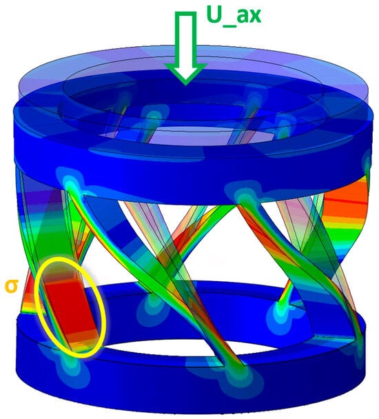
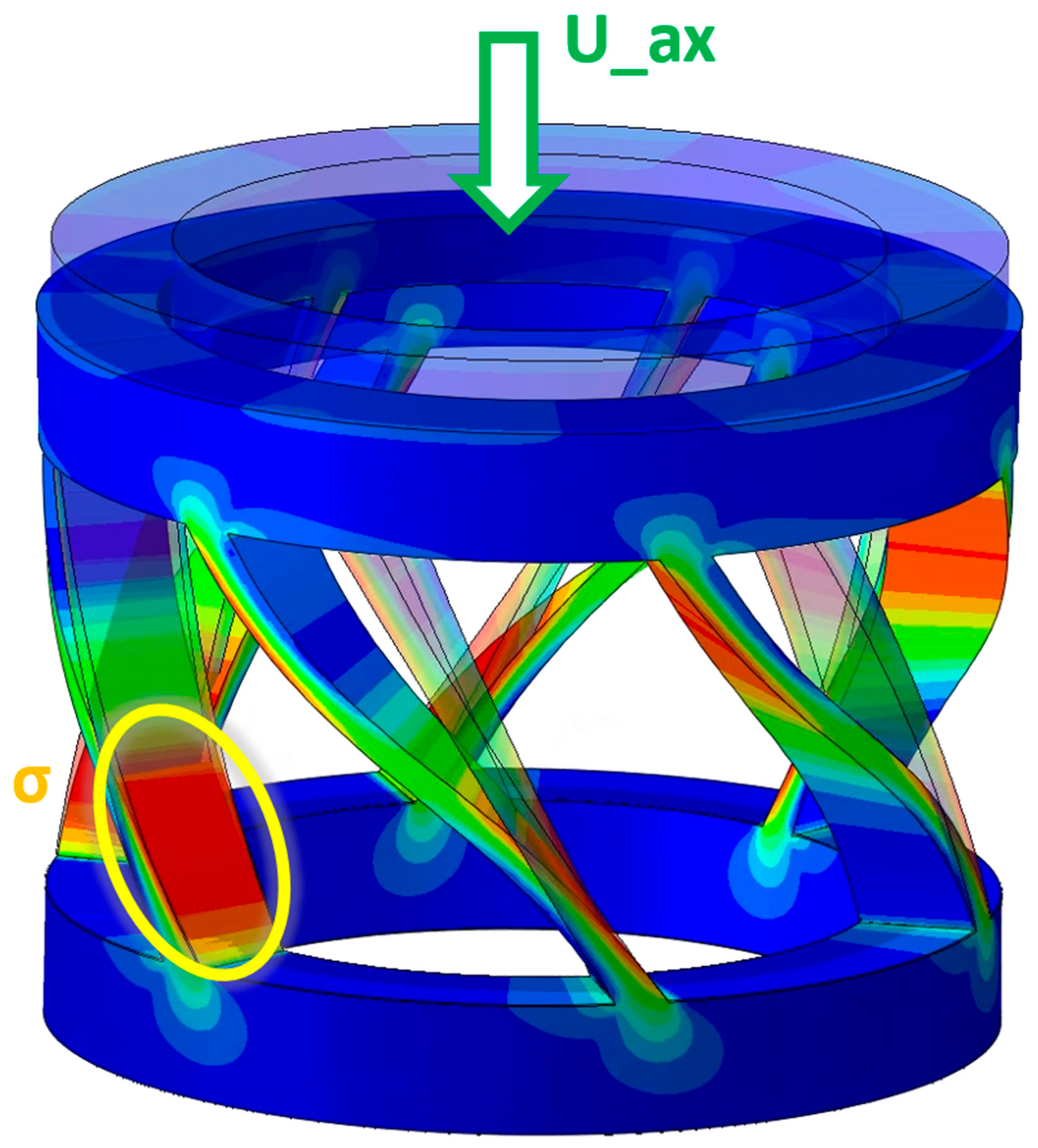
The current technical challenge is to create a torsion spring element that shortens proportionally in the axial direction under the effect of the torque acting on it and makes the torque acting on the body measurable by measuring the axial displacement. In order for the cyclist not to feel the elastic behavior of the spring when starting, a maximum of 1° rotation is allowed for the spring. Within this, the largest possible axial displacement must be achieved. In Figure 1 we can see a picture of the concept.
Figure 1.
Torsion spring concept with stress distribution plot.
3. Methods
3.1. Finite Element Method
A relatively simple finite element model was built in virtual space to describe the mechanical system in technical terms. Since the deformations are small for 1° rotation and we assume that the stresses remain below the yield point of the spring material, we use Hooke’s law, which describes stress and strain linearly, in our material model. In addition, since there are no nonlinear frictional contacts in the model, since we simulate only one component, the entire finite element model can be considered linear.
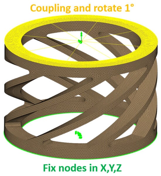
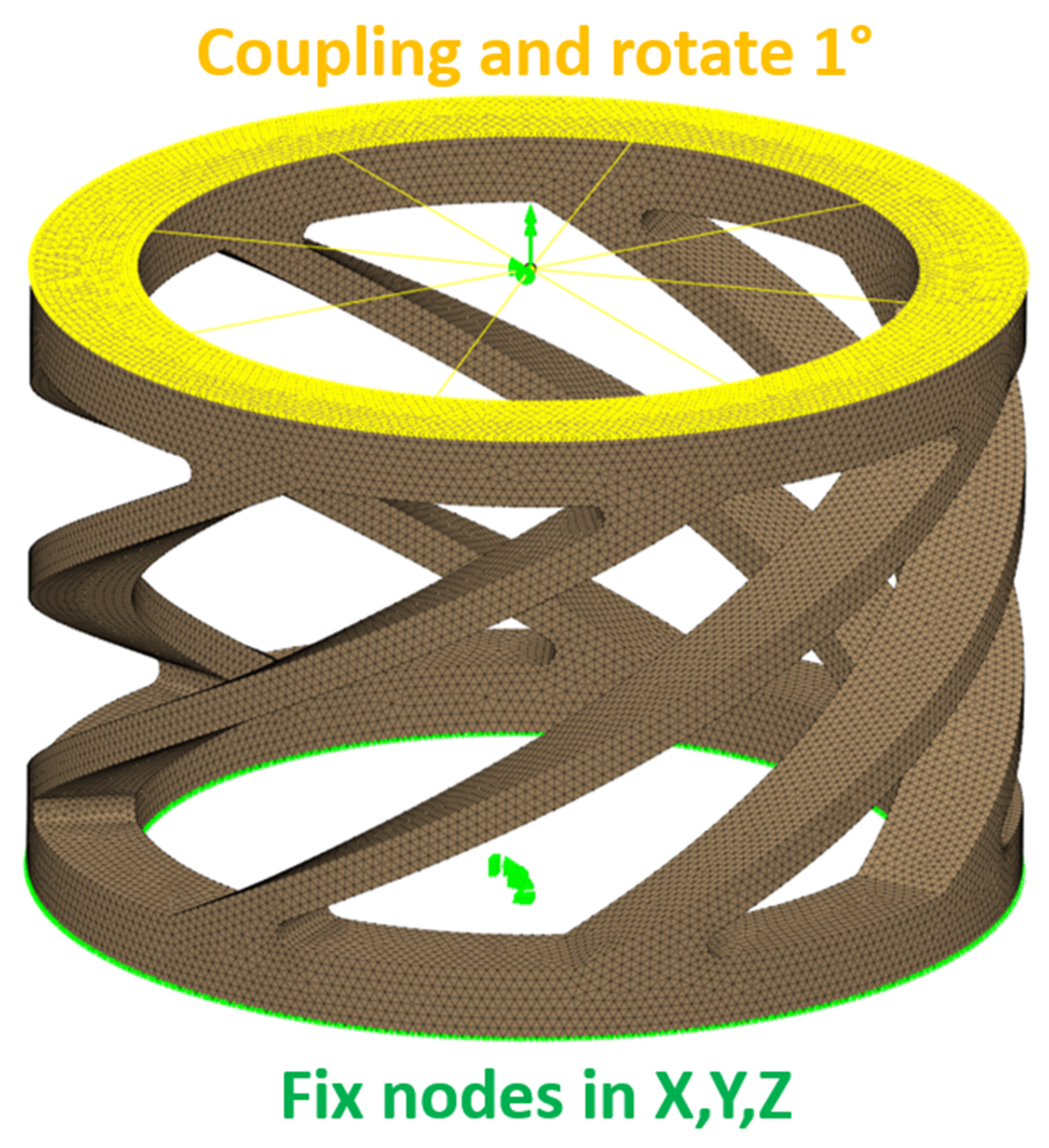
The geometry is meshed with 3D second-order tetra elements by the preprocessing software. The bottom face of the part is fixed with a grip and the top face is rotated using a Coupling element, as shown in Figure 2. Our spring is made of steel, which has an elastic modulus of 210 [GPa]. During the simulation, we measure the axial displacement of the coupling’s control node and the resulting reaction torque, as well as the largest first principal stress in the model. During the evaluation, we compared this principal stress to the fatigue strength determined by the material’s Wöhler curve, taking into account the properties of the steel used in the torsion element. Thus, the stress limit was determined to be 600 MPa.
Figure 2.
FEM simulation model with mesh, boundary conditions and coupling nodes.
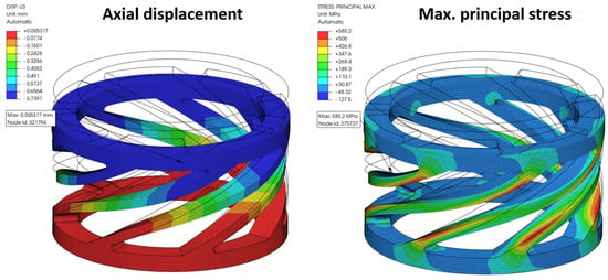
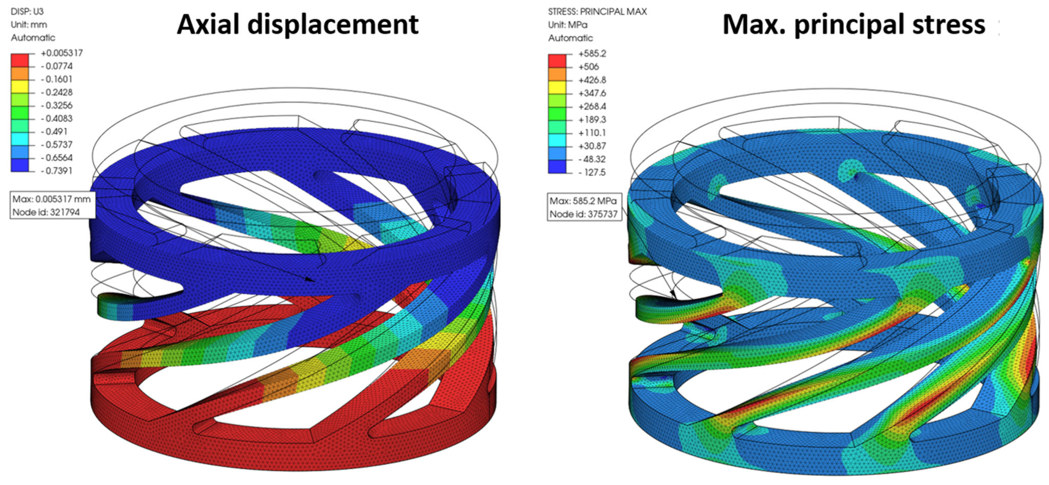
The results of the finite element model can be seen in Figure 3. It is clear that the most heavily stressed points are located at the edges of the springs where they are subjected to bending stress. A workflow has been developed that generates a CAD model by modifying geometric parameters, meshes the model, performs the analysis, and automatically evaluates the maximum stress and displacement.
Figure 3.
Simulation results of a possible design.
3.2. Generative Parameter Optimization
Genetic algorithms are stochastic optimization methods that introduce a degree of randomness into the search process to make the search for the optimum more efficient. These methods are less sensitive to modeling errors and try to avoid local optima in order to eventually converge to the global optimum. Genetic algorithms are inspired by the evolutionary theory of the origin of species and natural selection. Only individuals with the best combination of genes for a given environment have the opportunity to become dominant in their population and pass their genes on to the next generation for reproduction. In addition, genes sometimes undergo random changes that, if particularly advantageous for the survival of the individual, can lead to the evolution of a species into a new species.
Translated into mathematics,
- ‑
- A population is a set of individuals whose individuals meet the objectives and constraints of the optimization problem;
- ‑
- A generation is the population of each iteration;
- ‑
- Genes are the individual geometric variables;
- ‑
- Individuals are design variants with different values;
- ‑
- Dominant individuals are the Pareto-optimal solutions.
Optimization with a genetic algorithm is an iterative process: it usually starts from a randomly generated population of individuals, and as the search progresses, the objective functions of the individuals of the following populations increasingly approach the optimal value. The algorithm selects the fittest individuals from each generation, i.e., those that best satisfy the objective function, and then modifies their genes through recombination or random mutation to create a new generation.
Genetic algorithms use three operators to create new individuals from existing ones: selection, crossover, and mutation.
- ‑
- Selection consists of favoring better individuals based on an optimization objective function to allow them to pass on their genes to the next generation.
- ‑
- Crossover consists of two individuals from the parent generation that use their genetic information to create a new individual in the next generation. The goal is to produce individuals with better traits than the parents while maintaining the diversity of the population.
- ‑
- Mutation randomly modifies the genetic material of an individual to create a new pattern in the next generation. This introduces a degree of randomness into the search and allows for exploration of different regions of the design space, preventing premature convergence of the algorithm.
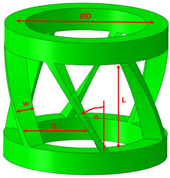
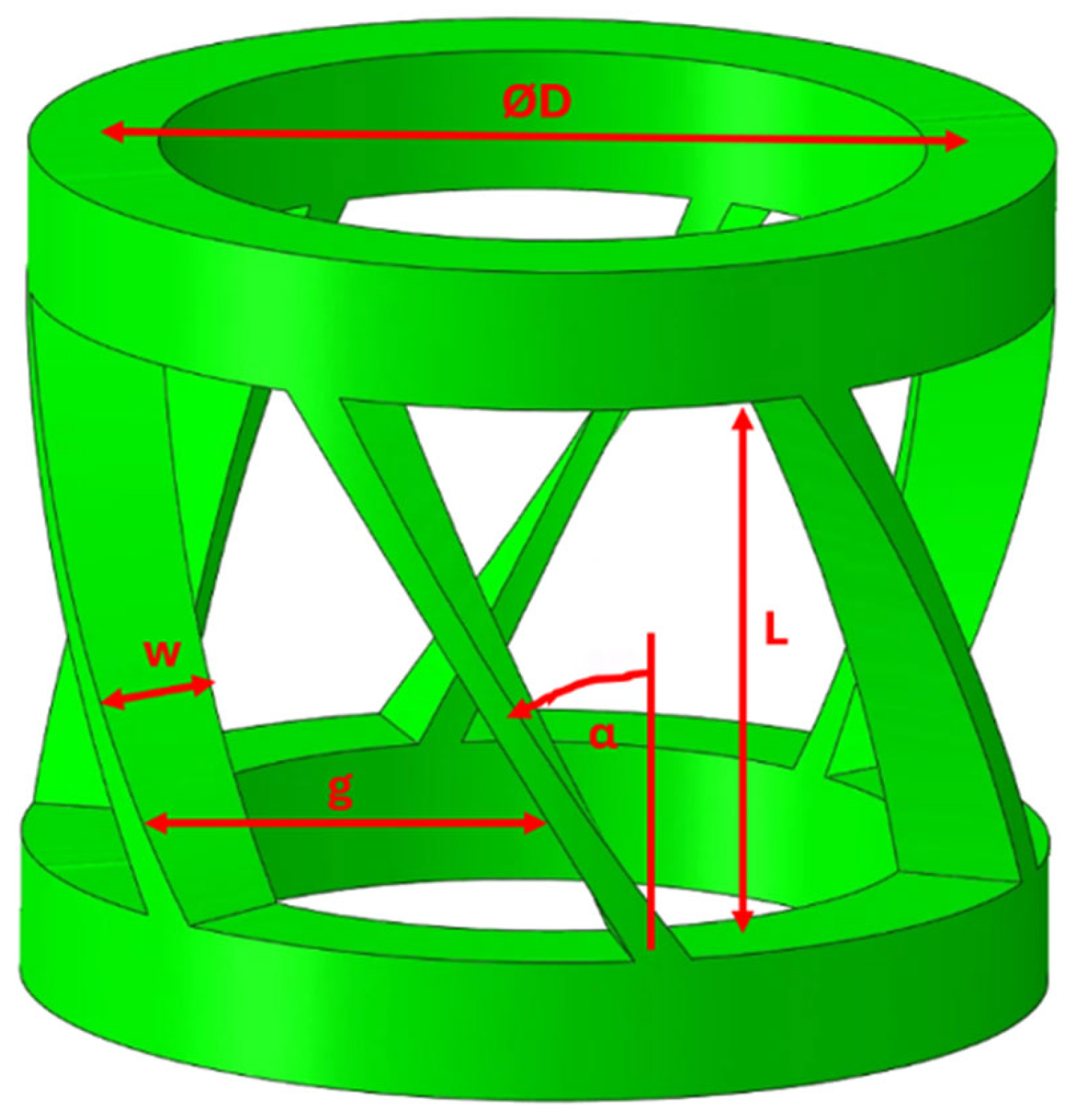
In our case, genes are essentially design parameters, and individuals are torsion spring geometries defined by a given design parameter combination. The design parameters can be seen in Figure 4.
Figure 4.
Design parameters of the torsion spring.
Where
- ▪
- D → the middle diameter of the spring;
- ▪
- w → width of a segment;
- ▪
- g → width of the recesses between the segments measured along the arc;
- ▪
- L → active length;
- ▪
- α → angle of spring segments;
- ▪
- n → number of spring segments.
The output quantities, which are also the objective functions of the optimization, are the following:
- ▪
- Uax → axial shortening due to torsion;
- ▪
- σ → maximum reduced mechanical stress in the structure due to loading.
During the process, our goal is to maximize the output quantity Uax and keep the voltage σ below a specified limit. This is a multi-objective optimization, since the relationship between the two quantities is inversely proportional, although the relationship is not clear-cut and can by no means be considered linear.
The Multi-Objective Genetic Algorithm (MOGA-II) is a patented version of the multi-objective genetic algorithm that uses an intelligent and efficient multi-search elitism that can preserve excellent (Pareto or non-dominated) solutions without prematurely converging to a local optimum. Elitism improves the convergence of the algorithm and helps ensure that the performance of each new generation is better than the performance of the parent generation. The elitism operator works as follows: The algorithm starts from an initial population, which is in our case 50 different random design combinations. The algorithm defines an empty elite set and uses operators to generate the offspring (the next generation). Each new individual is created with one of the following available operators:
- Selection: Copies the design variant or variants that perform best according to the objective function into the next generation
- Classical crossover: Two individuals of the parent generation exchange their genetic material to create a new design variant in the next generation. The goal is to create individuals with better traits than the parents while maintaining the diversity of the population. If the probability of classical crossover is high, the algorithm can more easily explore different regions of the design space (greater robustness), but this slows down its convergence.
- Mutation: The genetic material of an individual is randomly modified to create a new individual in the next generation. This operator introduces a degree of randomness into the search and allows different regions of the design space to be explored, preventing the algorithm from prematurely converging.
The algorithm then calculates the performance of all individuals (designs) in the generation to determine which design variant is the best. All non-dominated design variants are copied and stored as an elite set. Each time this operation is performed and new design variants are added to the elite set, duplicate and dominant designs are removed, and the elite set is reduced to the population size by randomly removing redundant individuals. The next generation is calculated using the MOGA operators, based on the designs from the parent population (selected from the previous generation based on their performance) and the elite set. If elitism is not applied, then each subsequent generation is calculated based on the design variants of the parent generation only. The procedure is repeated until the maximum number of generations is reached, which is in our case 10 generations. During the definition of next generations we used the following parameters: 5% selection, 85% classical crossover and 10% mutation.
4. Results
Ultimately, a total population of 1000 individuals was evaluated over 10 generations. This resulted in a total of 1000 different FEM models. The MOGA2 algorithm generated the 709th individual, which best met the requirements. During the design space search, only 76 feasible designs were generated that did not exceed the specified stress value. From the 76 suitable individuals, we ultimately selected the one with the largest axial displacement, whose parameters are:
- D = 61.5 [mm];
- w = 7.1 [mm];
- L = 34 [mm];
- α = 60°;
- n = 7;
- g = 11 [mm].
The displacement resulting from these model parameters and the mechanical stress induced in the root are:
- Uax = 0.73 [mm];
- σ = 581.6 [MPa].
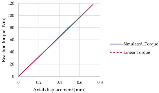
Although the simulations were run using a linear material model and without non-linear contacts, the model took geometric non-linearities into account (NLGEOM = YES). This means that the solver also takes the deformed geometry during the equilibrium calculations. An advantage of the resulting torque sensor is the almost completely linear torque–displacement relationship over small angular ranges, as illustrated in Figure 5. There is minimal deviation between the linear torque rise projected onto the final torque and the torque rise measured in the simulation.
Figure 5.
Torque–displacement curve.
Target values may vary depending on the application area and the size of the installation environment. The purpose of this publication is not to specify concrete values, but rather to describe the procedure used to determine the ideal geometry. It is important to note that the geometry has been defined with the understanding that it can be machined using conventional cutting methods, in this case milling. In the future, we will determine the ideal geometry for a torsion spring with complex geometry produced using additive manufacturing technology.
Author Contributions
Conceptualization, B.K. and B.L.; methodology, B.L. and I.H.; software, B.L.; validation, B.L. and I.H.; formal analysis, B.K.; investigation, B.L.; resources, I.H.; data curation, B.L.; writing—original draft preparation, B.L.; writing—review and editing, I.H.; visualization, B.L.; supervision, B.K.; project administration, I.H. All authors have read and agreed to the published version of the manuscript.
Funding
This research received no external funding.
Institutional Review Board Statement
Not applicable.
Informed Consent Statement
Not applicable.
Data Availability Statement
The original contributions presented in this study are included in the article. Further inquiries can be directed to the corresponding author.
Conflicts of Interest
The authors declare no conflicts of interest.
References
- Zhang, G.; Zhang, B.; Yao, Y.; Zhang, R.; He, S. High-resolution non-contact torque measurement for rotating shafts with helicoid-coded rings and differential chromatic confocal sensing. Results Eng. 2026, 30, 111160. [Google Scholar] [CrossRef] [Scilit]
- Bini, R.R.; Hume, P.A.; Cerviri, A. A comparison of cycling SRM crank and strain gauge instrumented pedal measures of peak torque, crank angle at peak torque and power output. Procedia Eng. 2011, 13, 56–61. [Google Scholar] [CrossRef] [Scilit]
- Panzani, G.; Radrizzani, S.; Dragonetti, T.; Savaresi, S.M. Virtual-bike control for a series human-powered electric bike via internal model control. Control Eng. Pract. 2026, 173, 106973. [Google Scholar] [CrossRef] [Scilit]
- Kurosawa, T.; Fujimoto, Y. Torque Sensorless Control for an Electric Power Assisted Bicycle with Instantaneous Pedaling Torque Estimation. IEEJ J. IA 2017, 6, 124–129. [Google Scholar] [CrossRef] [Scilit]
- Martín-Sosa, E.; Chaves, V.; Alvarado, I.; Mayo, J.; Ojeda, J. Design and Validation of a Device Attached to a Conventional Bicycle to Measure the Three-Dimensional Forces Applied to a Pedal. Sensors 2021, 21, 4590. [Google Scholar] [CrossRef] [Scilit] [PubMed]
- Ho, P.-J.; Yi, C.-P.; Lin, Y.-J.; Chung, W.-D.; Chou, P.-H.; Yang, S.-C. Torque Measurement and Control for Electric-Assisted Bike Considering Different External Load Conditions. Sensors 2023, 23, 4657. [Google Scholar] [CrossRef] [Scilit] [PubMed]
Disclaimer/Publisher’s Note: The statements, opinions and data contained in all publications are solely those of the individual author(s) and contributor(s) and not of MDPI and/or the editor(s). MDPI and/or the editor(s) disclaim responsibility for any injury to people or property resulting from any ideas, methods, instructions or products referred to in the content. |
© 2026 by the authors. Licensee MDPI, Basel, Switzerland. This article is an open access article distributed under the terms and conditions of the Creative Commons Attribution (CC BY) license.