


Abstract
The goal of this paper is to present a methodology developed to detect feedback loops within complex MATLAB/Simulink-based digital twins. Digital twins are developed using mathematical equations that describe the behavior of the given physical system in environments such as MATLAB/Simulink (2024a). During the implementation of these equations as block diagrams following a causal modeling approach, it is almost unavoidable to use feedback loops, which can cause many problems if the digital twin is not properly designed. Using the presented methodology, these loops within the model can be quickly identified, allowing the user to check them immediately and determine whether the source of a model error is associated with the given loop, e.g., a not-a-number (NaN) value stuck in the loop. This can be especially useful if the source of error is already partly localized and the goal is to narrow down the possible sources as fast as possible.
1. Introduction
Virtual development plays a key role in the development of complex systems, and processes like X-in-the-Loop (XiL) simulations have become almost unavoidable in many industries to keep pace with development competition. In virtual development, digital twins are used instead of physical prototypes, offering several advantages, especially in the early stages of development [1,2].
Modifying digital twins is much easier than modifying a physical prototype, which is a huge advantage during early design iterations because modifications can be made within the simulation or design environment without remanufacturing the affected part of the product. Furthermore, digital twins can be used to simulate rare or dangerous situations, making fine-tuning the product much easier. This is especially important in systems (e.g., vehicles and airplanes), where the safe testing of safety-critical electronic control units (ECUs) would be unimaginable without virtual development methods in the early stages. Thanks to virtual development, these safety-critical ECUs can be tested as many times as needed in a simulated environment until the software running on them meets the quality, reliability, and maturity required for real-life testing [3].
Finally, it must be noted that using digital twins, the number of tests running simultaneously is limited only by computational resources, whereas with physical prototypes, both the number of available prototypes and the conditions for the given tests are limiting factors [4,5].
Of course, it must be mentioned that virtual development and digital twins have some limitations as well. Firstly, the accuracy of digital twins must be recognized as a significant limitation. On the one hand, the required accuracy must be achieved to pass the tests and, if necessary, run simulations in real time, while on the other hand, the models must be simplified to reduce unnecessary complexity and save computational resources. Finding the right balance between accuracy and simplicity can be really challenging during the development process. Secondly, creating digital twins requires extensive knowledge, not only of the system itself but also of the principles of model-based design (MBD). This closely aligns with the first limitation because, without these competencies, finding the right balance between accuracy and simplicity is almost impossible, and finding people with the necessary skill set is also challenging [6].
Lastly, the complexity of error analyses and signal backtracing must be noted as a potential limitation. The reason behind this is that during XiL simulations, the digital twin representing the system, called the plant model, is mostly unchanged during all the stages of XiL simulations, while the controller is a mathematical model during the Model-in-the-Loop (MiL) simulation, the controller software during Software-in-the-Loop (SiL) simulation, and the real ECU with the controller software during Hardware-in-the-Loop (HiL) simulation. This means that the plant model must be compatible with various forms of controllers, and the source of error within the plant must be identified efficiently. This can be challenging because, on the one hand, the plant model can include not only the physical system itself but also simulated buses, which can further complicate the analysis. On the other hand, the plant model is used in different environments during the process, e.g., MATLAB/Simulink for MiL, Synopsys Silver for SiL, and dSPACE ControlDesk for HiL, meaning that the plant model must be compatible with all of these environments, and it must be usable not only in real-time environments but also in environments with lower and higher simulation speeds [7,8]. In this article MATLAB 2024a was used.
Most studies on XiL simulations, digital twins, and virtual development focus on simulation results, the accuracy of digital twins, and the importance and benefits of virtual development [9,10]. However, the number of studies focused on error analysis and signal tracing is limited, especially those on dedicated errors or elements that often cause problems in digital twins [11]. This is why this study focuses on establishing an automated methodology that enables people to identify feedback loops within digital twins.
2. Materials and Methods
As previously noted, this research focuses on developing a methodology to efficiently identify feedback loops to support the error analysis of digital twins used for XiL simulations. Simulink provides support for detecting poorly designed feedback loops (such as algebraic loops); however, the methodology presented in this paper focuses on identifying feedback loops in the digital twin and tracing them back from the part of the model where the error was noticed. This can be crucial when it is known that the Simulink-based digital twin model was properly designed, yet errors still occur during simulation. A good example of this is a NaN error, which can occur on the input side of the system and can become stuck within one of the feedback loops, resulting in a NaN value as the system’s output. In even worse situations, a NaN value can be stuck in one of the feedback loops, causing only a faulty output. In such cases, localizing all the feedback loops near the point where the error was noticed can be crucial for saving time and running the simulation again without complications.
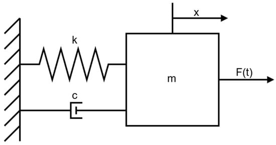
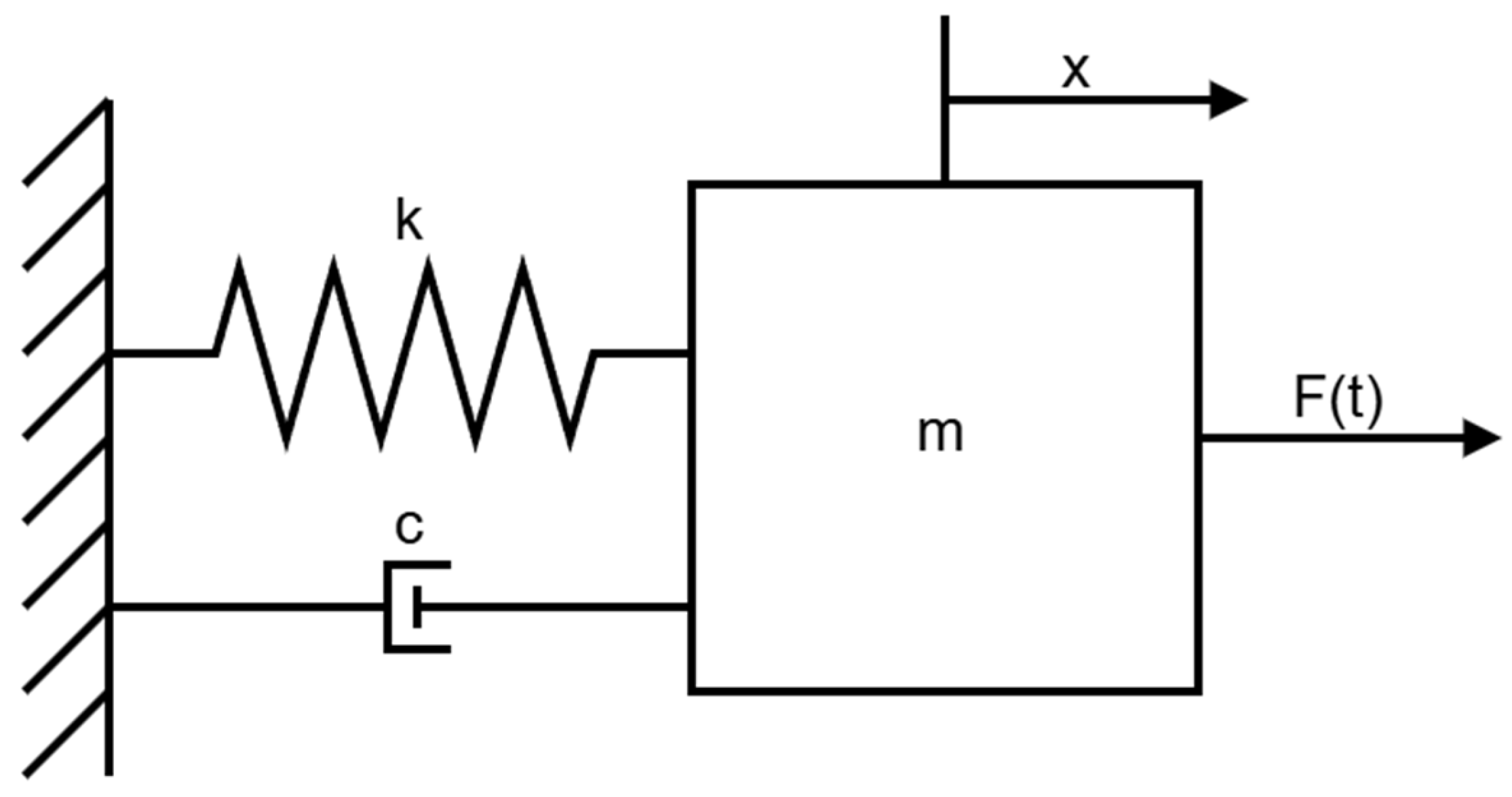
The methodology presented in this paper was tested by using some complex models used for XiL simulations containing many feedback loops. However, to illustrate how common feedback loops are in MATLAB/Simulink models, a mass-spring-damper system will be used as an example, serving as the basis for many complex digital twins in vehicle dynamics. The mass-spring-damper system is shown in Figure 1.
Figure 1.
Mass-spring-damper system.
This system can be described by using the following equations:
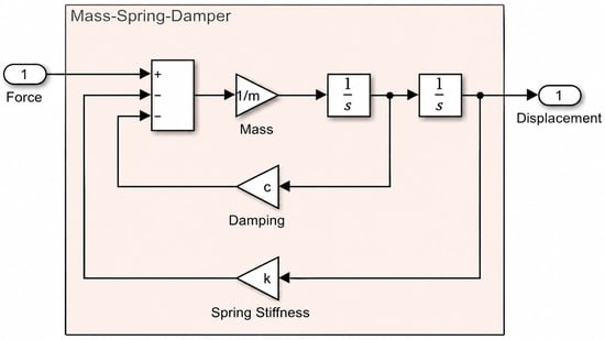
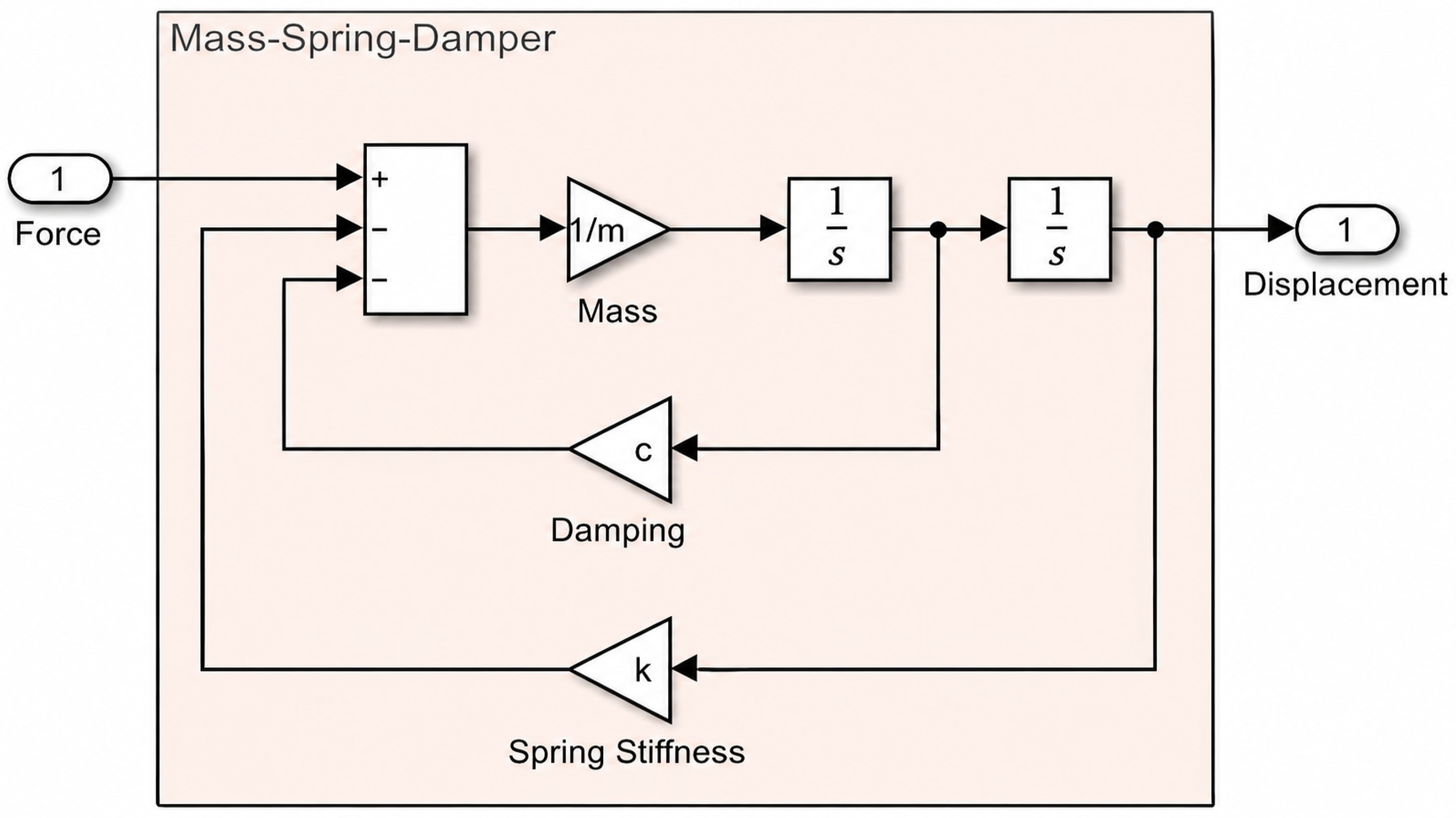
This type of system was chosen because it can be easily modeled in MATLAB/Simulink, yet it still contains enough complexity to represent the challenges posed by feedback loops within a digital twin, as shown in Figure 2.
Figure 2.
Mass-spring-damper system in MATLAB/Simulink.
As shown in Figure 2, the mass-spring-damper system designed in MATLAB/Simulink contains 2 feedback loops, providing a good example to present our new methodology by using it.
To create this new methodology, a solution presented in one of our previous research papers was taken as the basis [11]. This solution was designed to boost the efficiency of signal backtracking during error analysis within complex MATLAB/Simulink-based digital twins. It uses data available within the Simulink models to convert blocks of the model into graph nodes and signal lines into edges. After this conversion, the methodology can treat these digital twins as directed graphs, providing a way to map the model itself and navigate within the system of complex digital twins in a fast and efficient way [11].
3. Results and Discussion
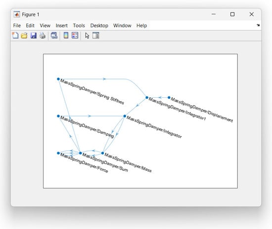
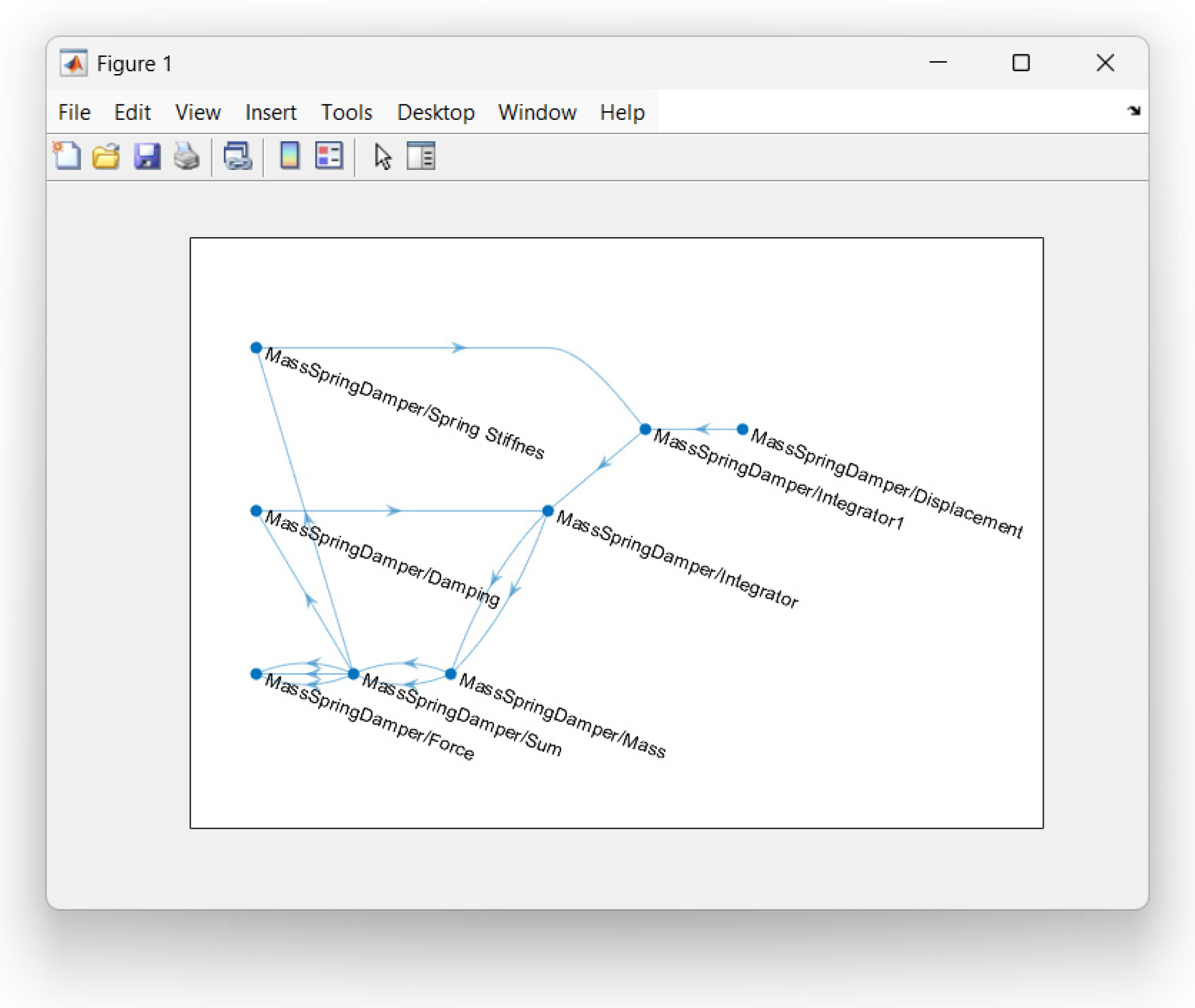
Based on the previously mentioned signal backtracking solution, a new methodology was developed to detect feedback loops in MATLAB/Simulink models. This new methodology takes advantage of treating the model as a system of directed graphs. By doing this, the entire model can be mapped backward from the output (displacement) and represented as a directed graph in a fully automated way, as shown in Figure 3.
Figure 3.
The MATLAB/Simulink model of the mass-spring-damper system represented as a directed graph.
The directed graph shown in the 3rd figure can be used for further analysis and to identify feedback loops within the system. Of course, it must be pointed out that in the case of such simple models, it is easy to see and to find the feedback loops; in the case of a system of complex digital twins consisting of hundreds of models and subsystems (e.g., the digital twin of a vehicle), seeing and finding these loops is not that easy anymore.
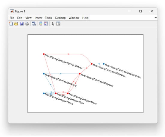
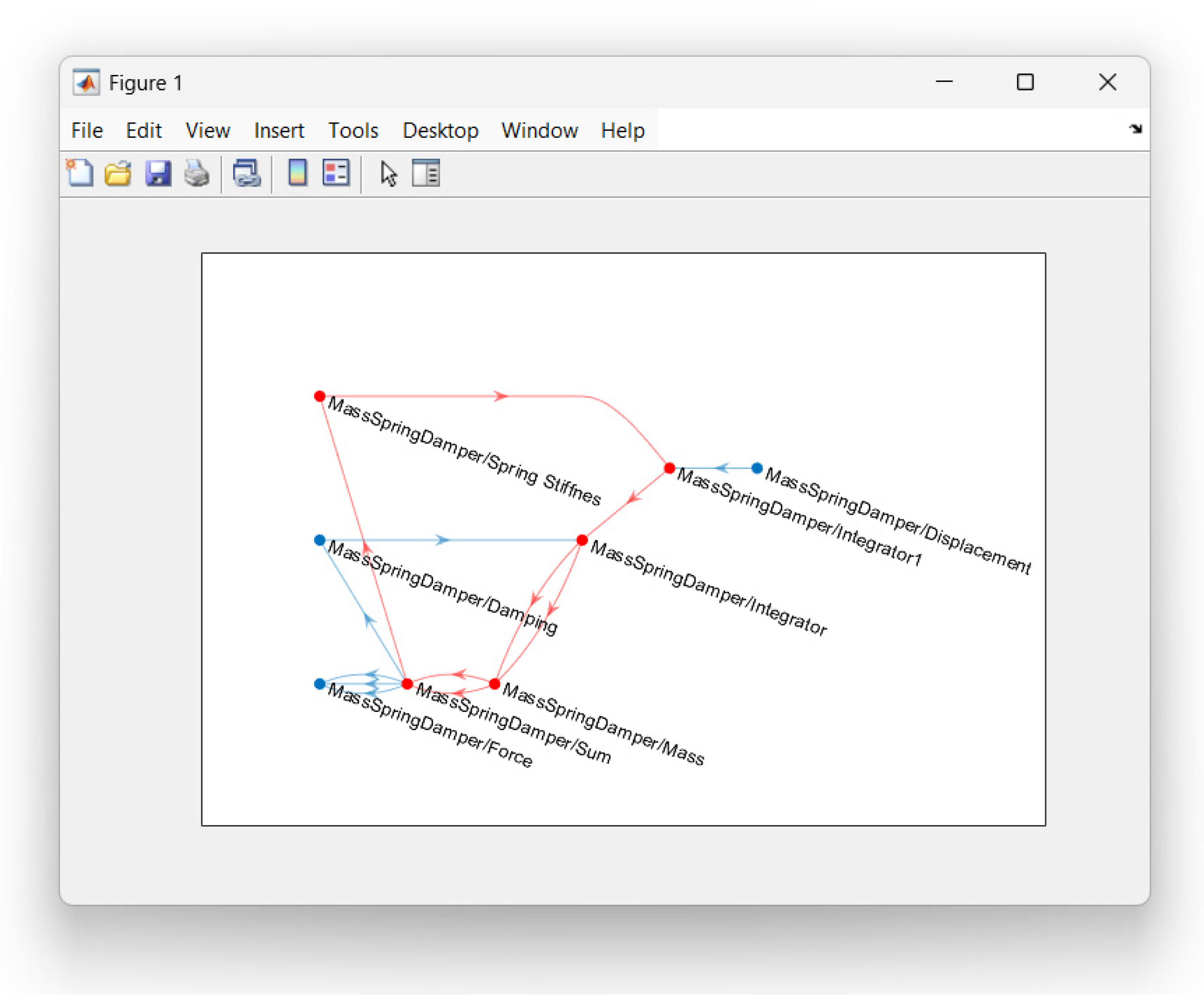
In the case of this new methodology, the previous solution was so extended that the algorithm being used became able not only to track back the source of the given signal and represent the results as a directed graph but also to make a difference between the elements of the signal chain and to identify if they are forming a loop within the digital twin. By doing so, this methodology became suitable to search for feedback loops within the digital twin, as shown in Figure 4.
Figure 4.
Feedback loop closest to the starting point detected in the Simulink model of the mass-spring-damper system.
As shown in Figure 4, the methodology being developed not only detects the feedback loop but also marks it with red in the directed graph representation of the digital twin, which can be a significant advantage during error analysis of a complex model. However, it can be observed that the algorithm developed for the methodology identified only one loop in the directed graph; this is because it is designed to detect the closest loop to the error location. By doing so, the mapping of the system and the loop detection run much faster, and the finding of only one loop supports keeping the focus during the analysis process, but it is planned to extend the methodology in a way that it can find and mark all the loops within the system to support some more specific analysis goals. This future extension can significantly increase the usability of this methodology within the industry; hence, it can reduce the challenge caused by taking over and already developed models from suppliers and then maintaining them, which is a common practice among automotive manufacturers.
4. Conclusions
Based on the results, a new methodology was developed to detect feedback loops within MATLAB/Simulink-based digital twins of complex systems. By using this methodology, finding the source of certain errors, such as NaN errors, can be significantly easier than traditional methods, such as manual analysis of the given model. However, this methodology has some limitations, as previously presented, because it is designed to detect only the feedback loop closest to the location where the error occurred. Of course, it can already be a significant advantage in the analysis of digital twins, but further development and optimization of the methodology can significantly increase its effectiveness and usability.
It must also be mentioned that the methodology can bring significant benefits during the analysis process of complex digital twins, especially in the industry where model development, integration and testing are generally conducted by multiple teams, meaning that in the case of an error, the first analysis is mostly made by someone having a lower knowledge of the models being used. What is more, the methodology can also be used to find the critical point within unknown and legacy models.
This is why our future research will focus on optimizing the methodology presented in this paper to detect all feedback loops within the mathematical model, thereby making the localization and so the analysis even faster and more efficient. On the other hand, the methodology underlying this feedback loop detection solution must be further optimized to enable more solutions like this. After these, the methodology can also be integrated into automated workflows, especially for MiL, where it could be used to test whether NaN errors can be stuck within the system or not; by doing so, the possibility of potential NaN errors during SiL and HiL could be significantly reduced.
Author Contributions
Conceptualization, J.R.L. and D.F.; methodology, J.R.L. and I.S.; software, J.R.L. and I.S.; validation, J.R.L.; formal analysis, J.R.L.; investigation, J.R.L.; resources, J.R.L.; data curation, J.R.L.; writing—original draft preparation, J.R.L.; writing—review and editing, I.S.; visualization, J.R.L.; supervision, D.F. All authors have read and agreed to the published version of the manuscript.
Funding
This research was funded by the 2025-2.1.2-EKÖP-KDP-2025-00012 University Research Scholarship Program (EKÖP) of the Ministry of Culture and Innovation from the source of the National Research, Development and Innovation Fund.
Institutional Review Board Statement
Not applicable.
Informed Consent Statement
Not applicable.
Data Availability Statement
The original contributions presented in this study are included in the article. Further inquiries can be directed to the corresponding author.
Conflicts of Interest
The authors declare no conflicts of interest. The funders had no role in the design of the study, in the collection, analyses, or interpretation of data, in the writing of the manuscript, or in the decision to publish the results.
Abbreviations
The following abbreviations are used in this manuscript:
| x | displacement (m) |
| F(t) | Sum of forces (N) |
| m | mass (kg) |
| c | damping coefficient |
| k | spring constant |
References
- Lauff, C.A.; Kotys-Schwartz, D.; Rentschler, M.E. What is a Prototype? What are the Roles of Prototypes in Companies? J. Mech. Des. 2018, 140, 061102. [Google Scholar] [CrossRef] [Scilit]
- Rehberg, L.; Brem, A. Industrial Prototyping in the German Automotive Industry: Bridging the Gap between Physical and Virtual Prototypes. J. Eng. Technol. Manag. 2024, 71, 101798. [Google Scholar] [CrossRef] [Scilit]
- Askaripoor, H.; Hashemi Farzaneh, M.; Knoll, A. E/E Architecture Synthesis: Challenges and Technologies. Electronics 2022, 11, 518. [Google Scholar] [CrossRef] [Scilit]
- Bringmann, E.; Krämer, A. Model-Based Testing of Automotive Systems. In Proceedings of the 2008 1st International Conference on Software Testing, Verification, and Validation, Lillehammer, Norway, 9–11 April 2008; pp. 485–493. [Google Scholar] [CrossRef] [Scilit]
- Szalay, Z. Next Generation X-in-the-Loop Validation Methodology for Automated Vehicle Systems. IEEE Access 2021, 9, 35616–35632. [Google Scholar] [CrossRef] [Scilit]
- Mihalič, F.; Truntič, M.; Hren, A. Hardware-in-the-Loop Simulations: A Historical Overview of Engineering Challenges. Electronics 2022, 11, 2462. [Google Scholar] [CrossRef] [Scilit]
- Shylla, D.; Jain, A.; Shah, P.; Sekhar, R. Model in Loop (MIL), Software in Loop (SIL) and Hardware in Loop (HIL) Testing in MBD. In Proceedings of the 2023 4th IEEE Global Conference for Advancement in Technology (GCAT), Bangalore, India, 6–8 October 2023; pp. 1–6. [Google Scholar] [CrossRef] [Scilit]
- Bacic, M. On hardware-in-the-loop simulation. In Proceedings of the 44th IEEE Conference on Decision and Control, Seville, Spain, 15 December 2005; pp. 3194–3198. [Google Scholar] [CrossRef] [Scilit]
- Thorat, S.; Pawase, R.; Agarkar, B. Modelling and Simulation-Based Design Approach to Assisted and Automated Driving Systems Development. In Proceedings of the 2024 International Conference on Emerging Smart Computing and Informatics (ESCI), Pune, India, 5–7 March 2024; pp. 1–8. [Google Scholar] [CrossRef] [Scilit]
- Faithfull, P.T.; Ball, R.J.; Jones, R.P. An investigation into the use of hardware-in-the-loop simulation with a scaled physical prototype as an aid to design. J. Eng. Des. 2001, 12, 231–243. [Google Scholar] [CrossRef] [Scilit]
- Lennert, J.R.; Fodor, D.; Szalay, I. Development of an Automated Solution for the Error Analysis of MATLAB/Simulink-Based Digital Twins. Eng. Proc. 2025, 113, 49. [Google Scholar] [CrossRef] [Scilit]
Disclaimer/Publisher’s Note: The statements, opinions and data contained in all publications are solely those of the individual author(s) and contributor(s) and not of MDPI and/or the editor(s). MDPI and/or the editor(s) disclaim responsibility for any injury to people or property resulting from any ideas, methods, instructions or products referred to in the content. |
© 2026 by the authors. Licensee MDPI, Basel, Switzerland. This article is an open access article distributed under the terms and conditions of the Creative Commons Attribution (CC BY) license.