


Abstract
This study investigates the hardness characteristics of various cold- and hot-formed sheet materials, with particular emphasis on the local material changes induced by different cutting technologies. Although work hardening during cold forming is well known, the development of new tools and cutting processes makes it important to re-examine the hardening generated during cutting. The aim is to determine the extent to which thermal and purely mechanical sheet-processing methods influence the hardness of finished parts, and to interpret the differences in terms of the deformation and thermal mechanisms involved. The study is based on hardness measurement, so those mechanisms are inferred from the measured profiles and the process conditions rather than confirmed microstructurally. Four steel and aluminium sheet materials commonly used in industrial practice were examined; for each, machine-based and manual cutting methods were compared, including laser cutting, guillotine shearing, punching, and slitting. Significant work hardening occurred in specimens affected by mechanical cold-forming processes, whereas the aluminium alloy and the laser-cut steel showed no appreciable hardening. The results indicate that the hardness of the final product is influenced not only by the forming method, but also to a considerable extent by the selected cutting technology.
Keywords:
sheet materials; hardness; cutting technologies; cold forming; hot forming; work hardening 1. Introduction
Sheet-metal cutting is one of the most widely used operations in manufacturing, and the quality of the cut edge has a direct influence on the performance of the finished part. Localized deformation introduced during cutting alters the material in the immediate vicinity of the edge, affecting properties such as hardness, formability, and fatigue resistance [1]. In mechanical cutting processes—shearing, slitting, and punching—the material in the shear-affected zone (SAZ) undergoes severe local plastic deformation, which raises dislocation density and produces measurable work hardening that decays with distance from the edge [2,3]. This deformation proceeds through characteristic rollover, burnish, fracture, and burr regions, and its severity is governed by the interaction between the cutting tool and the material microstructure [4]. The effect is well documented for high-strength and dual-phase steels, where sheared-edge damage is known to degrade subsequent forming and fatigue behaviour [5,6].
Although work hardening during cold forming is itself a long-established phenomenon, the continual development of new tools, materials, and cutting processes makes it necessary to re-examine the hardening generated during specific cutting operations [7]. The magnitude of edge hardening depends not only on the process but also on process parameters such as cutting clearance and tool condition, and on the material being cut: ductility, strength, and microstructure all influence the response [8,9]. The depth of the shear-affected zone is commonly quantified through microhardness profiles taken at increasing distance from the cut edge, the hardness levelling off to the bulk value at the end of the zone [10]. Thermal cutting processes introduce a different mechanism. Instead of mechanical deformation, the heat input creates a heat-affected zone whose extent and effect on hardness depend strongly on the material’s thermal conductivity and on the sheet thickness, with thin sheets dissipating heat rapidly and thus experiencing comparatively limited thermal effects [11,12].
Despite the extensive literature on individual processes, direct comparisons across mechanical and thermal cutting technologies for a range of industrially relevant sheet materials—measured under identical hardness-testing conditions—remain limited. This is the gap addressed in the present work. The aim of this study is to determine the extent to which different cutting technologies influence the near-edge hardness of finished sheet parts, and to interpret the observed differences in terms of the deformation and thermal mechanisms at work. The study rests on microhardness measurement; the mechanisms are therefore inferred from the hardness profiles and from the process conditions, and are not confirmed by microstructural examination. Four sheet materials commonly used in industrial practice were examined, and for each, a machine-based cutting process (laser cutting, guillotine shearing, punching, or slitting) was compared against manual sheet-shear cutting as a low-deformation control. The hardness changes induced at the cut edges are quantified and interpreted with reference to the forming mechanism and the material behaviour.
2. Materials and Methods
This study examined four sheet materials representative of those commonly used in industrial sheet-metal processing: DC53 tool steel, S250GD galvanized structural steel, AlMnMg0.5 (EN AW 3005) aluminium alloy, and DC01 low-carbon cold-rolled steel, all supplied by thyssenkrupp Components Technology Hungary Kft. (Jászfényszaru, Hungary). The materials were selected to cover a range of mechanical behaviours and to allow the effects of different cutting technologies to be compared across both ferrous and non-ferrous sheets. For each material, a machine-based cutting process was paired with manual sheet-shear cutting, which served as a low-deformation control in every case. This pairing made it possible to isolate the microstructural changes induced by each machine-based technology on the same specimen.
2.1. Materials and Cutting Technologies
The four machine-based cutting technologies investigated were guillotine shearing, slitting, punching, and laser cutting. Because slitting was applied to two different materials, the experimental design comprised five measurement cases in total, summarized in Table 1. The DC53 tool steel is characterized by good dimensional stability, toughness, and wear resistance, making it suitable for applications involving high loads, such as precision pressing and cold forging. The S250GD galvanized steel offers good formability together with high strength and corrosion resistance provided by its protective zinc coating. The AlMnMg0.5 aluminium alloy exhibits good formability under both cold and hot working and good corrosion resistance, with manganese and magnesium as the principal alloying elements. The DC01 low-carbon cold-rolled steel is characterized by good formability and is well suited to laser cutting, providing uniform cut edges. The four machine-based cuts were not produced under controlled laboratory conditions but reached the laboratory as part of the normal industrial supply of the material, and this constrains how far their parameters can be reported. The guillotine shearing was the exception: it was carried out in-house on a DIGÉP OL-3 guillotine shear (DIGÉP, Miskolc, Hungary). The laser cutting was carried out by an external laser-cutting service on a TRUMPF TruLaser 3030 CO2 laser cutting machine (TRUMPF, Ditzingen, Germany) with nitrogen as the assist gas; the laser power and cutting speed actually applied to this sheet were not recorded. The punching was performed with a cutting clearance of 3% of the sheet thickness, which corresponds to about 12 µm for the 0.41 mm sheet concerned. The slitting was carried out with rotating circular knives on the supplier’s slitting line. Several quantities remain unknown: the laser power and cutting speed used for this sheet, the punch and die diameters, and the geometry and cutting clearance of the slitting knives; these were not recorded or not disclosed to the authors and are therefore not reported. The gaps are limitations of the study rather than omissions, and they are discussed in Section 4.
Table 1.
Materials, cutting technologies, and measured sheet thicknesses. Manual sheet-shear cutting served as the control in all cases.
2.2. Specimen Preparation
Square specimens measuring 21 × 21 mm were prepared from each material. The machine-based cuts (guillotine shearing, slitting, punching, and laser cutting) were performed as described in Section 2.1, while the final trimming to size was carried out using a manual sheet-shear cutter so that both a machine-cut edge and a manually cut edge were present on each specimen. Before cutting, the thickness of every sheet was measured with a Mitutoyo (Kawasaki, Tokyo, Japan) caliper and a digital micrometer, taking the average of three repeated measurements. The edges produced by each technology were marked to ensure correct specimen orientation and reproducibility during measurement. Owing to the small sheet thickness, the specimens were hot-mounted in Bakelite (phenolic resin) using Buehler (Lake Bluff, IL, USA) equipment to allow stable, perpendicular indentation during hardness testing. The surfaces were cleaned and degreased before mounting, which was carried out at 180 bar and 200 °C with an 8 min cycle and produced 40 mm diameter mounts; each specimen was positioned so that at least 5 mm of resin surrounded it in every direction. The mounted cross-sections were then ground on water-cooled SiC papers of P180, P320 and P600 grit and finally P800, the specimen being rotated continuously to avoid directional scratching, and polished on a cloth wheel with 9 µm and 3 µm diamond paste under light pressure and constant movement to prevent local heating. Each specimen was then cleaned with ethanol and a microfibre cloth to remove polishing residue. Particular care was taken with the thinnest sheets to avoid deformation.
2.3. Hardness Measurement
Hardness was measured using a KB Prüftechnik KB 30 (Buehler) automated microhardness tester (KB Prüftechnik, Hochdorf-Assenheim, Germany) operating on the Vickers principle, with software-based evaluation of the indentations. This system enables low-load, high-resolution measurements and allows the indentation contour to be corrected during evaluation. A load of HV0.1 (a test force of 0.1 kgf) was applied. The low load was chosen so that the indentation would remain small enough to capture the microstructural changes occurring in the immediate vicinity of the cut edge—such as work hardening from plastic deformation or structural modification within the heat-affected zone of laser cutting—rather than the properties of the deeper, unaffected material. For each material, a reference (base) hardness was first determined at the centre of the specimen, in a region free from any processing effects, by averaging three indentations. Ten indentations were then made along each cut edge, spaced 0.1 mm apart and beginning 0.1 mm from the edge, to track the variation in hardness as a function of distance from the cut. Ten indentations were used because the hardness varied locally as a result of forming and the specimen microstructure was not fully homogeneous. The indentations were evaluated by the instrument software with visual verification of every indentation contour, and the test force, dwell time and indentation spacing were identical for all specimens, so the cases are directly comparable with one another. It should be noted that each location was indented once: the standard deviations quoted below therefore describe the variation in hardness along the profile, and are not a repeatability estimate of the hardness measurement itself. The base hardness of each material rests on only three indentations; their scatter is reported in Table 2 and is small in every case, but three readings remain a thin baseline for materials with local microstructural heterogeneity. Both points are taken up in Section 4.
Table 2.
Summary of base hardness and edge hardness (HV0.1) for all five measurement cases. Every edge value is the mean ± standard deviation of the ten indentations of a single traverse (n = 10), with the range in parentheses; the standard deviation therefore describes the variation along the profile. The base hardness is the mean ± standard deviation of three indentations made at the centre of the specimen, in a region free from processing effects.
3. Results
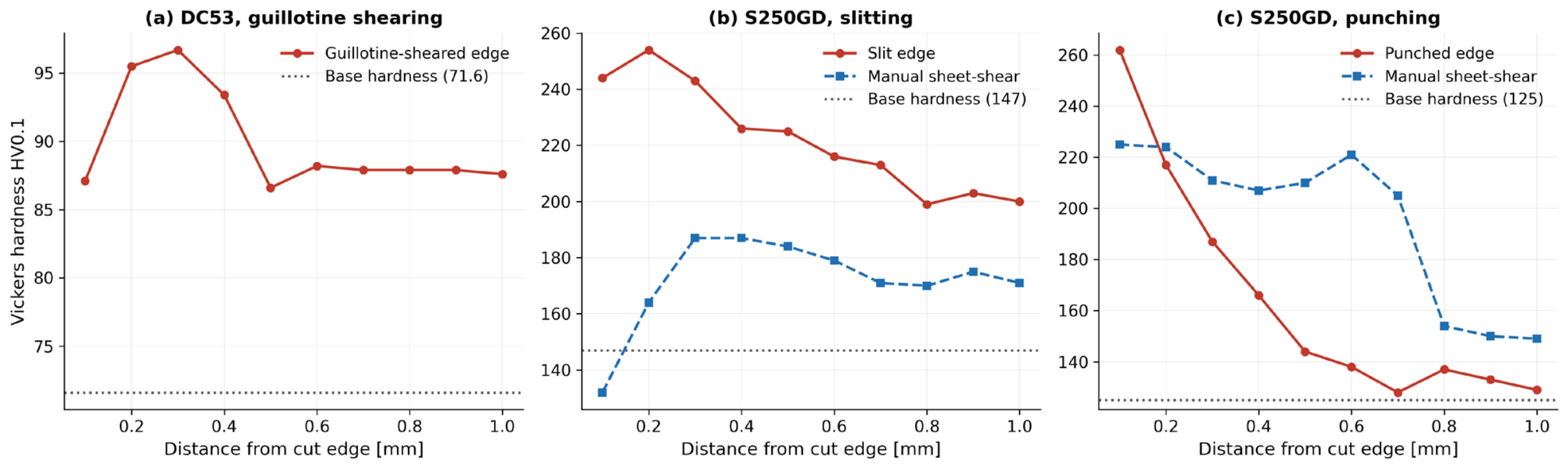
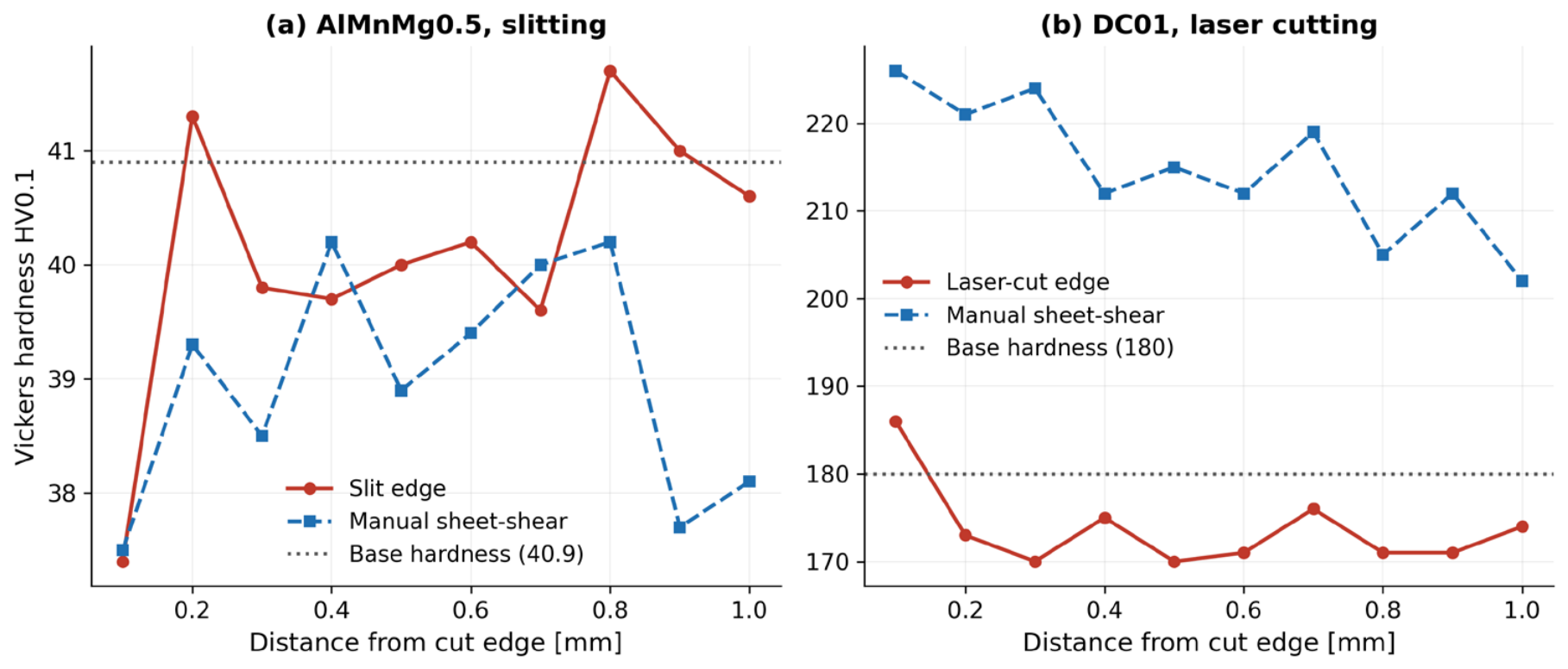
For each material, the base hardness measured at the centre of the specimen is reported together with the hardness measured along the machine-cut and manually cut edges. Unless otherwise noted, edge values are based on ten indentations. The hardness profiles are shown in Figure 1 (steels) and Figure 2 (aluminium and laser-cut steel), and the results for all five measurement cases are summarized in Table 2.
Figure 1.
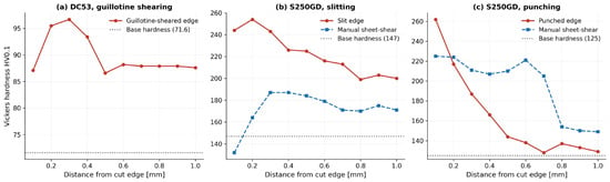
Microhardness profiles as a function of distance from the cut edge for the steels: (a) DC53 tool steel, guillotine shearing; (b) S250GD galvanized steel, slitting; (c) S250GD galvanized steel, punching. Each symbol is a single indentation, ten per traverse, spaced 0.1 mm apart; the dotted line marks the base hardness of the material. For the DC53 specimen the manually cut edge was not recorded, so only the guillotine-sheared profile is shown.
Figure 2.
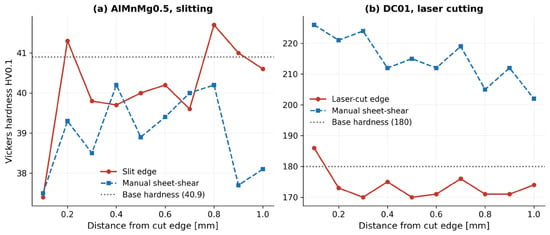
Microhardness profiles as a function of distance from the cut edge: (a) AlMnMg0.5 aluminium alloy, slitting; (b) DC01 steel, laser cutting. Each symbol is a single indentation, ten per traverse, spaced 0.1 mm apart; the dotted line marks the base hardness of the material.
3.1. Guillotine-Sheared DC53 Tool Steel
The base hardness of the DC53 tool steel was 71.6 HV0.1 (mean of three indentations; the individual readings were not recorded for this material). Along the guillotine-sheared edge, hardness increased only slightly, ranging from 86.6 to 96.7 HV0.1 (mean 89.9 ± 3.8 HV0.1, n = 10). The manually cut edge of the same specimen was inspected and appeared comparable, but its individual indentation values were not recorded, so no quantitative comparison is possible for this material; this gap is stated as a limitation in Section 4. For the guillotine-sheared edge itself, both the modest magnitude of the increase and its uniformity along the profile indicate that no pronounced hardening developed at the edge.
3.2. Slit S250GD Galvanized Steel
The base hardness was 147.0 ± 3.5 HV0.1 (n = 3). The slit edge showed pronounced work hardening, with values from 199 to 254 HV0.1 (mean 222.3 ± 19.6 HV0.1, n = 10); the highest values occurred immediately adjacent to the cut edge. The manually cut edge of the same material reached a maximum of 187 HV0.1 (mean 172.0 ± 16.1 HV0.1, minimum 132 HV0.1, n = 10), with hardness lowest near the edge and increasing toward the interior—well below the values produced by slitting.
3.3. Punched S250GD Galvanized Steel
The base hardness was 125.0 ± 4.6 HV0.1 (n = 3). Along the punched edge, hardness peaked at 262 HV0.1 immediately adjacent to the cut and then decreased toward the specimen interior, falling to 128 HV0.1 (mean 164.1 ± 45.0 HV0.1, n = 10). The manually cut edge reached a maximum of 225 HV0.1 (mean 195.6 ± 31.6 HV0.1, n = 10) and maintained relatively uniform values near 200 HV0.1 before decreasing toward the interior. Both methods produced clear work hardening, but with different through-depth profiles: a steep decay for punching and a more gradual one for manual shearing.
3.4. Slit AlMnMg0.5 Aluminium Alloy
The base hardness of the aluminium alloy was 40.9 ± 0.4 HV0.1 (n = 3), substantially lower than that of the steels. Neither the slit edge (37.4–41.7 HV0.1, mean 40.1 ± 1.2 HV0.1, n = 10) nor the manually cut edge (37.5–40.2 HV0.1, mean 39.0 ± 1.0 HV0.1, n = 10) showed any appreciable hardening; both remained close to the base hardness, with no outlying values.
3.5. Laser-Cut DC01 Steel
The base hardness of the DC01 steel was 180.0 ± 5.0 HV0.1 (n = 3). Contrary to expectation, the laser-cut edge showed no hardening: values ranged from 170 to 186 HV0.1 (mean 173.7 ± 4.8 HV0.1, n = 10), close to the base hardness. The manually cut edge of the same specimen, however, was clearly hardened, ranging from 202 to 226 HV0.1 (mean 214.8 ± 7.8 HV0.1, n = 10), with somewhat higher values near the cut.
4. Discussion
The results show that the hardness change induced at a cut edge depends strongly on both the material and the cutting technology, and that the two factors cannot be considered independently.
For the steels processed by mechanical cutting, the dominant trend was work hardening localized near the cut edge. Slitting and punching of the S250GD galvanized steel produced the most pronounced effect, with peak edge hardness reaching roughly 1.5 to 2 times the base hardness. This behaviour is consistent with the accumulation of dislocations during severe local plastic deformation: as dislocation density increases, the mobility of the crystal lattice is progressively restricted, which raises the measured hardness. The through-depth profiles support this interpretation. The punched edge showed a steep hardness peak immediately adjacent to the cut followed by a rapid decay toward the base hardness, whereas the manually sheared edge of the same material exhibited a more gradual decay. This difference reflects the more concentrated, higher-intensity deformation imposed by punching compared with the progressive deformation of manual shearing. The punching clearance of 3% of the sheet thickness lies at the tight end of the range normally used for steel sheet, which favours a large burnished fraction on the cut surface and hence intense plastic deformation immediately behind the edge; the steep, high peak measured at the punched edge is consistent with this, and with the known sensitivity of near-edge damage to cutting clearance and punch geometry [4,9].
The guillotine-sheared DC53 tool steel showed only a modest increase in hardness at the edge. The comparatively high alloy content and the pre-hardened, dimensionally stable condition of this tool steel likely limit the extent of additional work hardening achievable through shearing, so that the deformation introduced at the edge produces only a small change relative to the base material.
The aluminium alloy behaved markedly differently from the steels. Neither slitting nor manual shearing produced any appreciable hardening, with all edge values remaining close to the base hardness. The contrast with the galvanized steel—cut by the same slitting process—demonstrates that the response to a given cutting technology is strongly material-dependent. It also underlines a practical point: avoiding undesired edge hardening is a matter of selecting an appropriate base material as well as an appropriate cutting process.
The most notable result was obtained for the laser-cut DC01 steel. Laser cutting is a thermal process, and edge hardening was expected from the heat input and subsequent rapid cooling. Instead, the laser-cut edge showed no hardening, remaining close to the base hardness, while the manually cut edge of the same specimen was clearly hardened. A likely explanation is the small sheet thickness: in a thin sheet, heat is conducted away rapidly, reducing the thermal gradients and the extent of any hardening transformation at the edge. The material itself may also contribute, since the low-carbon composition of DC01 limits the potential for hardening transformations. The process gas points in the same direction: the cut was made under nitrogen rather than oxygen, so no exothermic oxidation reaction added heat at the kerf, and the total heat input—and with it the extent of any heat-affected zone—is correspondingly smaller than in oxygen-assisted cutting of the same material. This result should not be generalized to all thermal cutting processes: more aggressive thermal technologies, such as flame or plasma cutting, can be expected to introduce considerably greater hardening around the cut edge. Rather, it indicates that for thin, low-carbon sheet, laser cutting can produce a clean edge without the work hardening associated with mechanical cutting—an advantage when subsequent forming or fatigue performance is a concern.
The magnitudes observed here have practical consequences for downstream processing. Near-edge hardening of the order seen for the slit and punched galvanized steel—roughly 1.5 to 2 times the base hardness within the first few tenths of a millimetre—corresponds to material that has already consumed part of its formability before any forming operation begins, which is the condition associated in the literature with edge cracking during subsequent flanging, hole expansion or stretch forming, and with reduced fatigue life when the cut edge lies in a tensile-loaded region [5,6]. Where such operations follow the cut, the results argue for choosing the cutting technology with the downstream step in mind rather than based on cutting cost and throughput alone: for the thin low-carbon sheet studied here, laser cutting left the edge essentially at base hardness, whereas punching and slitting did not. Conversely, where the cut edge is not subsequently formed or cyclically loaded, the same hardening is of little practical consequence and the cheaper mechanical process remains appropriate.
Several limitations should be noted, and they set the terms on which these results should be read. The most important is that the sheet thickness differed between the materials, from 0.41 mm for the punched galvanized steel to 1.22 mm for the guillotine-sheared tool steel, and this matters in two distinct ways. Mechanically, the depth of the shear-affected zone scales with sheet thickness, so the fixed 1 mm profile used here does not sample the same relative depth in every case: it extends to roughly 2.4 times the sheet thickness in the 0.41 mm punched sheet, but to only about 0.8 times the thickness in the 1.22 mm DC53 sheet. A traverse that reaches well beyond the shear-affected zone in one material may therefore still lie within it in another, which is one reason the decay behaviour differs between cases. Thermally, heat dissipation during laser cutting likewise scales with thickness, so the absence of hardening at the laser-cut edge of the 1.02 mm DC01 sheet cannot be carried over to thicker sheet. Differences between the materials therefore cannot be attributed to the material or to the cutting technology alone, and the comparison should be read as indicative rather than as a controlled ranking.
No microstructural investigation was carried out. The mechanisms invoked above—dislocation accumulation in the shear-affected zone, and the absence of a hardening transformation at the laser-cut edge—are consistent with the measured profiles and with the literature, but they remain interpretations of hardness data rather than observations. The mounted specimens are no longer available, so confirming them would require etched cross-sections and optical or electron microscopy on newly prepared samples.
Three further constraints follow from how the measurements were made. The base hardness of each material rests on three indentations only. Their scatter is now reported in Table 2 and is modest (from ±0.4 HV0.1 for the aluminium alloy to ±5.0 HV0.1 for the DC01 steel), which supports the baseline values used here, but three readings remain few for materials with local microstructural heterogeneity, and for the DC53 specimen only the mean was recorded. Each measurement case rests on a single specimen and a single traverse, so the standard deviations in Table 2 describe the variation along one profile and not the reproducibility between specimens. And the individual readings along the manually cut edge of the DC53 specimen were never recorded, which leaves that one comparison qualitative.
Finally, as set out in Section 2.1, the process parameters are only partly known. The guillotine shear, the laser-cutting machine and its nitrogen assist gas, the 3% punching clearance and the use of rotating circular knives for slitting are documented; the laser power and cutting speed applied to this sheet, the punch and die diameters and the slitting-knife geometry are not. The differences reported here are therefore differences between industrially representative cuts rather than between parameter-controlled ones, which is the appropriate basis for selecting a process but not for isolating the effect of any single cutting parameter.
5. Conclusions
This study compared the near-edge hardness produced by four machine-based cutting technologies—guillotine shearing, slitting, punching, and laser cutting—against manual sheet-shear cutting, across four industrially relevant sheet materials. The main findings are as follows.
Mechanical cutting of the steels produced localized work hardening at the cut edge, most pronounced for slitting and punching of the galvanized steel, where peak edge hardness reached roughly 1.5 to 2 times the base hardness. The hardening decayed with distance from the edge, consistent with deformation-induced dislocation accumulation in the shear-affected zone.
The response was strongly material-dependent. The aluminium alloy showed no appreciable hardening under the same cutting processes, demonstrating that controlling edge hardening is a matter of material selection as well as process selection.
Contrary to expectation, laser cutting of the thin DC01 steel produced no hardening at the cut edge, while the manually cut edge of the same specimen was clearly hardened. This is attributed to rapid heat dissipation in the thin sheet and the low-carbon composition of the material. The result should not be generalized to all thermal processes, as more aggressive technologies such as flame or plasma cutting may induce considerably greater hardening.
Overall, the results show that the hardness of a finished sheet part is governed not only by the forming method but, to a considerable extent, by the chosen cutting technology and its interaction with the material. The study has clear limitations, set out in Section 4: the sheet thickness differed between materials, no microstructural examination was performed, each case rests on a single specimen, and the machine-based cuts were industrial supply cuts with undisclosed parameters. Future work should therefore use sheets of equal thickness and replicate specimens per condition, record the cutting parameters, confirm the proposed mechanisms metallographically, and extend the comparison to further thermal and mechanical processes such as flame, plasma and water-jet cutting and to a wider range of steel and aluminium alloys.
Author Contributions
Conceptualization, S.S. and S.Á.V.; methodology, S.S. and S.Á.V.; investigation, S.Á.V. and S.S.; data curation, S.Á.V.; writing—original draft preparation, S.Á.V.; writing—review and editing, S.S.; visualization, S.Á.V.; supervision, S.S. All authors have read and agreed to the published version of the manuscript.
Funding
This research received no external funding.
Institutional Review Board Statement
Not applicable.
Informed Consent Statement
Not applicable.
Data Availability Statement
The data presented in this study are available on request from the corresponding author.
Conflicts of Interest
The authors declare no conflicts of interest.
References
- Golovashchenko, S.; Zhou, W.; Nasheralahkami, S.; Wang, N. Trimming and sheared edge stretchability of light weight sheet metal blanks. Procedia Eng. 2017, 207, 1552–1557. [Google Scholar] [CrossRef] [Scilit]
- Bohdal, Ł.; Kułakowska, A.; Patyk, R.; Kułakowski, M.; Szada-Borzyszkowska, M.; Banaszek, K. Experimental research on sheared edge formation in the shear-slitting of grain-oriented electrical steel workpieces. Materials 2022, 15, 8824. [Google Scholar] [CrossRef] [Scilit]
- Patyk, R.; Bohdal, Ł.; Kukielka, L.; Kukielka, K. Modeling and experimental analysis of shear-slitting of AA6111-T4 aluminum alloy sheet. Materials 2020, 13, 3175. [Google Scholar] [CrossRef] [Scilit]
- Bohdal, Ł. Effect of cutting clearance in shear-slitting process on the residual stress and cut surface quality of AA6111-T4 aluminum alloy. J. Mech. Eng. Sci. 2024, 18, 9824–9834. [Google Scholar] [CrossRef] [Scilit]
- Khalilabad, M.M.; Perdahcıoğlu, S.; Atzema, E.; van den Boogaard, T. Initiation and growth of edge cracks after shear cutting of dual-phase steel. Int. J. Adv. Manuf. Technol. 2023, 127, 2327–2341. [Google Scholar] [CrossRef] [Scilit]
- Gustafsson, D.; Parareda, S.; Sieurin, H.; Olsson, E. Estimating the effect of punching on out-of-plane bending fatigue of steel sheet specimens. Eng. Fail. Anal. 2025, 173, 109415. [Google Scholar] [CrossRef] [Scilit]
- Gustafsson, D.; Ronco, D.; Gallio, G.; Olsson, E. Estimating the effect of cold forming and post processing on fatigue of high strength steels under component-related loading conditions. Eng. Fail. Anal. 2026, 184, 110368, Correction in Eng. Fail. Anal. 2026, 191, 110759. https://doi.org/10.1016/j.engfailanal.2026.110759. [Google Scholar] [CrossRef] [Scilit]
- Chen, J.; Tu, F.; Wang, P.; Cao, Y. Revealing the enhancement mechanism of laser cutting on the strength–ductility combination in low carbon steel. Metals 2024, 14, 541. [Google Scholar] [CrossRef] [Scilit]
- Okada, R.; Ito, K.; Funazuka, T.; Aizawa, T.; Shiratori, T. Punch edge topological design for reduction of work hardening damage in shearing of non-oriented electrical steel sheets. Materials 2025, 18, 878. [Google Scholar] [CrossRef] [Scilit] [PubMed]
- Golovashchenko, S.F.; Nasheralahkami, S.; Pan, J.; Pan, K. Mechanism of fracture in sheet metal cutting processes and its effect on sheared edge stretchability. IOP Conf. Ser. Mater. Sci. Eng. 2018, 418, 012057. [Google Scholar] [CrossRef] [Scilit]
- Čačková, I.; Čačko, V.; Ferenczi, B.; Brusilová, A.; Šooš, Ľ.; Shabu, S. Experimental investigation and statistical optimization of dimensional accuracy and microhardness in fiber laser cutting of low-carbon steel sheets. J. Manuf. Mater. Process. 2026, 10, 174. [Google Scholar] [CrossRef] [Scilit]
- Selech, J.; Burzynski, G.; Tibebe, D.; Ulbrich, D.; Banas, P. Influence of laser cutting parameters on the microhardness, roughness, and microstructure of AISI 304, S355J2, and AlMg3 alloys. Materials 2026, 19, 240. [Google Scholar] [CrossRef] [Scilit] [PubMed]

Disclaimer/Publisher’s Note: The statements, opinions and data contained in all publications are solely those of the individual author(s) and contributor(s) and not of MDPI and/or the editor(s). MDPI and/or the editor(s) disclaim responsibility for any injury to people or property resulting from any ideas, methods, instructions or products referred to in the content. |
© 2026 by the authors. Licensee MDPI, Basel, Switzerland. This article is an open access article distributed under the terms and conditions of the Creative Commons Attribution (CC BY) license.