


Abstract
Machine vision and machine learning are playing an increasingly important role in manufacturing and autonomous vehicle applications. Reliable operation of such systems strongly depends on proper sensor calibration. One possible calibration method is to move a calibration target using a robotic arm; however, commercially available robotic manipulators are often too expensive for educational and research purposes. The aim of this research is therefore to develop a low-cost robotic arm for teaching and research applications. The paper presents the workflow of a systematic robotic design process, including conceptual design, functional decomposition, CAD modeling, simulation, optimization possibilities, and manufacturing aspects. Preliminary results of the CAD design and simulation process are also discussed. The reaction torques in the simulation were calculated as 0 Nm at Joint 1, −8.52 Nm at Joint 2, −1.37 Nm at Joint 3, 0 Nm at Joint 4, and 2.64 Nm at Joint 5 using a 0.5 kg load and the weight of the arms. Different drive system concepts are evaluated and compared in tabular form according to the principles of systematic design. The paper concludes by identifying the main limitations of the current design and outlining further research tasks.
1. Introduction
Machine vision and machine learning are playing an increasingly important role in manufacturing and autonomous vehicle applications. Reliable operation of such systems strongly depends on proper sensor calibration [1]. There are two types of sensor calibration: intrinsic, which is sensor-specific, and extrinsic, in which kinematic transformation between multiple sensors is estimated [2].
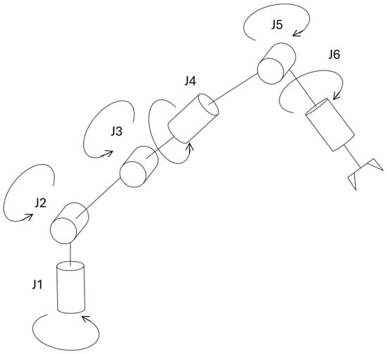
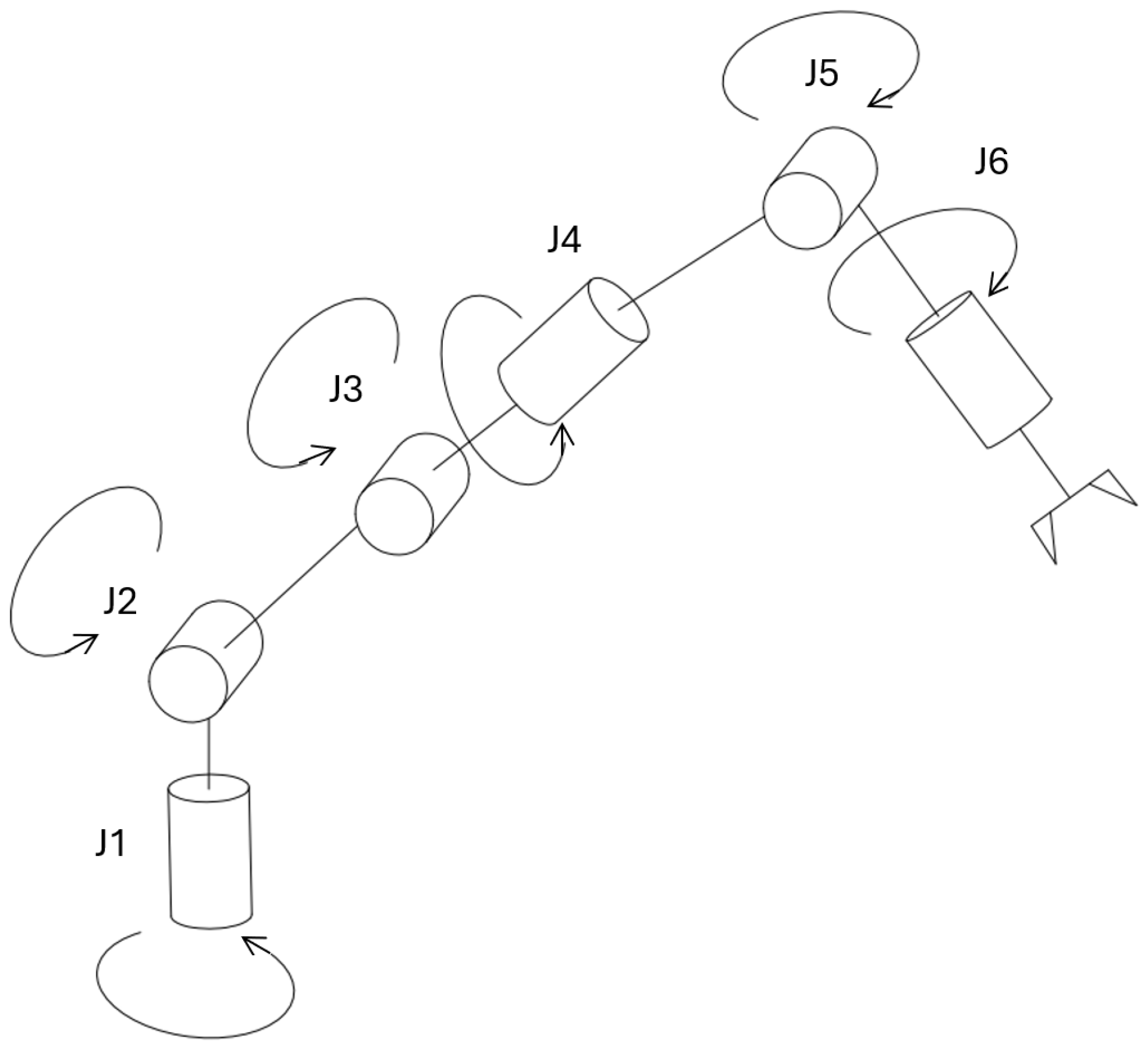
The aim of the research is therefore to develop a low-cost 6DOF robotic arm (Figure 1) for sensor calibration, which can be used for teaching and research tasks.
Figure 1.
The 6DOF robotic arm (based on [3]).
Sensor calibration is usually performed in a laboratory environment, where calibration tables and various objects are placed in different positions. However, the test scenarios are mostly organized by humans, which takes a lot of time, especially if there are a lot of scenarios [4]. Another option is to use robotic manipulators to create different scenarios [5]. The main drawback of this method is that commercial robotic arms are expensive or not suitable for various tasks [6].
Calibration itself is realized by dedicated estimation algorithms rather than by the manipulator. Intrinsic parameters are recovered from a known target by bundle adjustment, whereas extrinsic and hand–eye transforms are obtained by solving the homogeneous matrix equation AX = XB, the classical formulation of Tsai and Lenz [7]. For the automotive radar and camera sensors targeted here, the underlying calibration measurements and computational sensor models have been characterized in prior work [2], and for full multi-sensor rigs, target-based and targetless methods estimate the LiDAR–camera transformation automatically [8,9]. When a manipulator carries the calibration target, its own kinematic accuracy enters the error budget, so the arm is first kinematically calibrated by identifying its (modified) Denavit–Hartenberg parameters [10], and the measurement poses are selected to maximize an observability index [11]. In the present work, the robotic arm is therefore not a calibration solver but a repeatable positioning device that presents the target to the sensor under test. The estimation algorithms above, including the computational sensor models of [2], operate on the acquired sensor data. This separation is precisely what motivates the accuracy-driven drive-system selection in Section 3, since backlash and compliance at the joints would otherwise corrupt the pose that the calibration algorithm assumes to be known.
Using a systematic design, the applicability of four drive systems and their optimal joint placement in a six-degree-of-freedom (6DOF) robotic arm was investigated, considering the advantages and disadvantages of creating the elements by 3D printing.
2. Materials and Methods
Systematic Design
A robotic arm is a mechatronic system. It consists of a mechanical system, which contains the drive chain and the arms, the electrical system, like the energy system and the sensors, and the control system, which includes the software.
As the design process can be divided into multiple subtasks, in this paper, the systematic design of the mechanical system is presented in detail [12].
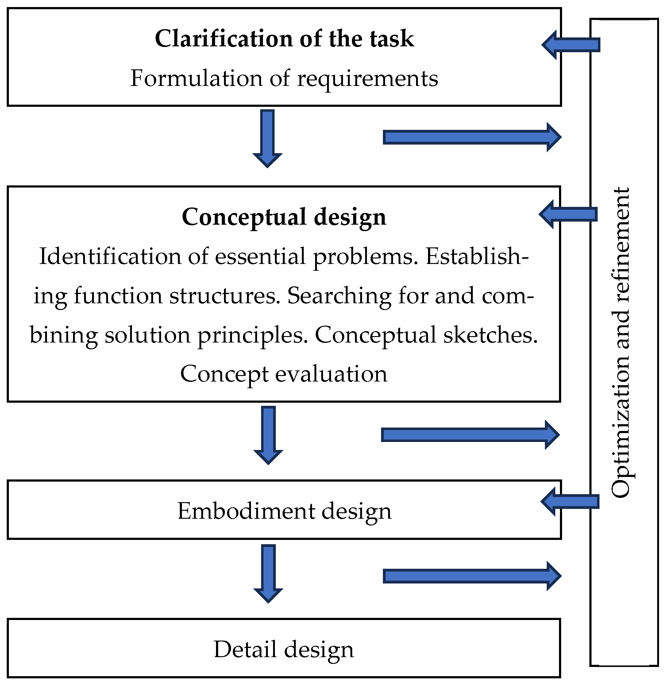
The essence of systematic design is methodical, or conscious, systems-based, and therefore non-instinctive design. The main steps of the design process are as follows [13] (Figure 2).
- Requirements and conceptual design;
- Concept formation;
- Design;
- Realization, prototyping.
Between these steps, there is continuous improvement and refinement.
The systematic design process of robotic systems is also similar. The main steps are product design specification, concept generation and evaluation, simplified mathematical modeling and simulation, parametric CAD model development, physical prototyping, and experimental validation [14]. Other studies approach the design process both from a systematic and task-oriented point of view [15].
In this paper, the first 2 steps of the design process are explained in detail. The third step, which is the design, has also been initiated, so the preliminary results of the design are also mentioned.
Figure 2.
Steps of the systematic design process (based on [13]).
3. Results
3.1. Requirements and Conceptual Design
The first step of the design process is to specify the task and the requirements. As the robotic arm will be used for research and educational tasks, the following requirements were specified:
- The mass of the calibration object does not exceed 500 g.
- The robot is able to move the calibration object in a 30 cm sphere.
- The robot must consist of replaceable parts.
- The specified joint speed of the robot is max. 2 m/s.
- The robot structure must be built from easily available materials.
- The robot structure must be as light as possible.
- The robot structure must be built from as few raw materials as possible.
3.2. Concept Formation
The critical element of a 6-DOF robotic arm is the transmission of the joints. The four investigated alternatives that can be implemented with 3D printing are the following:
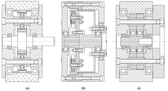
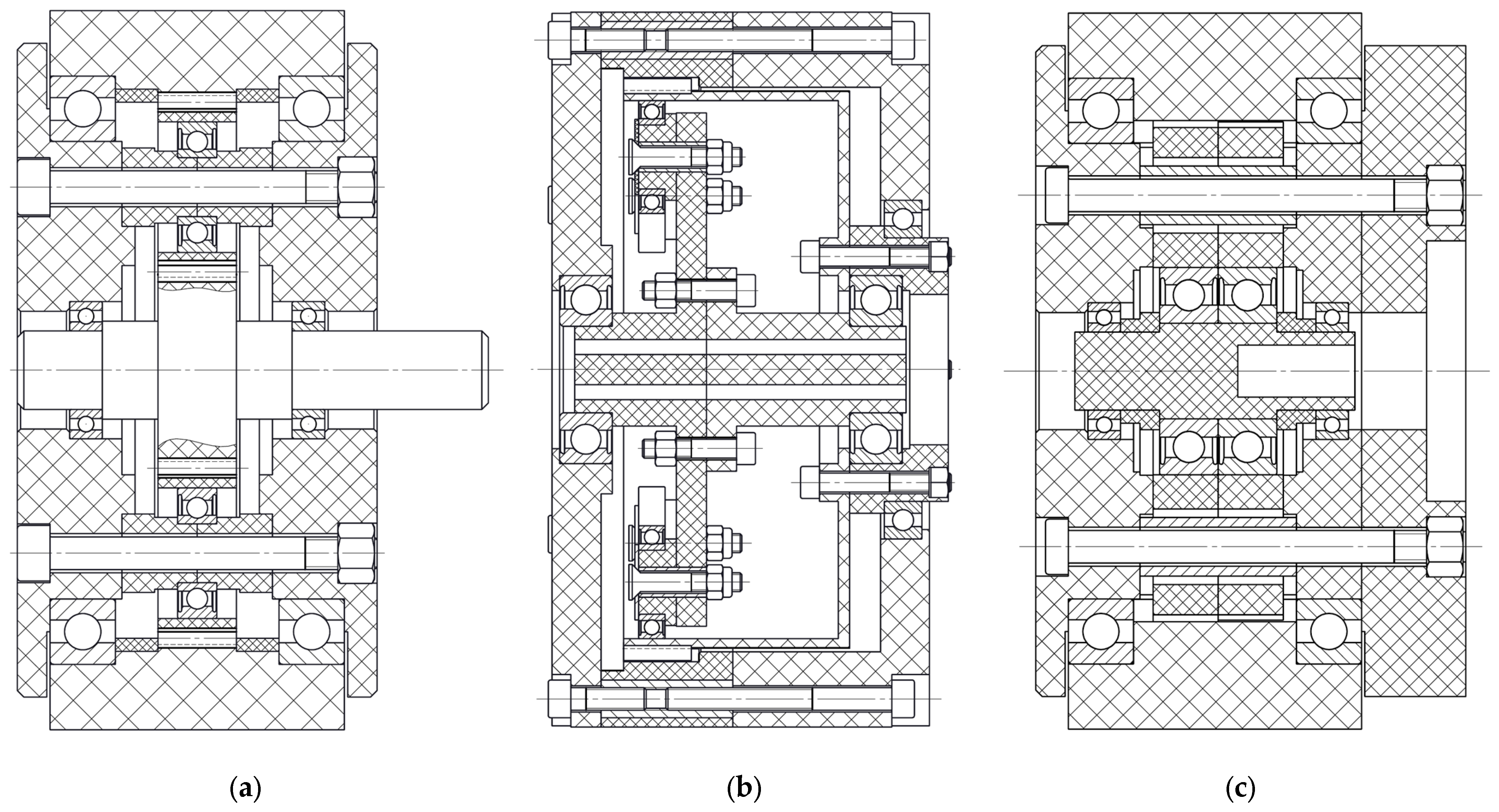
Planetary gear: one of the most common types in robotics. It is made up of four main components: a sun gear, planetary gears, a ring gear, and a planet carrier. The sun gear is the driving gear. The freely rotating planetary gears, which usually consist of three or four pieces, are held between the sun gear and the internally toothed ring gear. The last element is the planet carrier, which has several functions: it connects the shafts of the planetary gears and is also the output shaft. It is easy to print in both flat and herringbone designs. Solid, but has significant backlash when 3D printed and is difficult to fit without gaps (Figure 3a) [16] (pp. 438–455) [17].
Figure 3.
Example of a planetary gear (a), a cycloidal gear (b), and a strain wave gear (c).
Strain wave gear: it consists of a generator (exciter), an external toothed flexible wheel (wave wheel), an internal toothed rigid wheel, and a housing. As the generator rotates, the engagement zone of the teeth is continuously shifted. The wave wheel rolls on the internal toothed rigid wheel; i.e., for one revolution of the generator, the wave wheel rotates in the opposite direction by a division corresponding to the difference in the number of teeth. In terms of load capacity, the wave drive greatly surpasses traditional gear-based drives. The weight of the wave drive can be 1/3 or even 1/4 of the gear drives of the same design. Theoretically, it has zero backlash. However, the FDM 3D-printed flexible sleeve is prone to rapid fatigue or teeth skipping at high torque (Figure 3b) [16] (pp. 456–470) [18].
Cycloidal gear: it is an eccentric drive system based on rolling pins and a cycloidal contour disk instead of gears. The main structural elements include the eccentrically designed drive shaft, the eccentric, cycloidal disk, the roller ring, the drive pins, and the driven shaft. The appropriate design of the cycloidal curves allows for frictionless rolling and constant angular velocity. During the rotation of the eccentric disk attached to the drive shaft, the protruding part of the cycloidal disk penetrates between the adjacent rollers one after the other, while the cycloidal disk rotates in the opposite direction. It is extremely suitable for the first three main axes of robotic arms (Joint 1, Joint 2, Joint 3), where the highest torque and the lowest backlash are required. It has excellent torque density; the load is distributed across many contact points at once. It can be made of rigid, low-backlash printable PETG/ABS materials with standard steel roller reinforcement (Figure 3c) [16] (pp. 471–474) [19].
Belt drive: it is an excellent alternative for both professional and home-built 3D-printed robotic arms. It allows the motors to be placed at the back (at the base of the bogie), thus drastically relieving the rest of the arm and reducing dead weight. Due to the back location of the center of mass, it is particularly suitable for the last two joints (Joint 5, Joint 6). Its main features include high mechanical efficiency and low cost. It is almost backlash-free. However, at large spans, the belt can bring measurable flexibility to the system.
The advantages and disadvantages of the drive systems are summarized in Table 1.
Table 1.
Advantages and disadvantages of drive systems used in robotics (based on [16]).
The actuator suitability matrix for the joints of the six-degree-of-freedom (6-DOF) robot arm is contained in Table 2, from Joint 1 (J1) to Joint 6 (J6). Detailed tables can be found in the Appendix A.
Table 2.
Evaluation of drive systems for the joints of the robotic arm (based on [20]).
Using the gear suitability matrix, a cycloidal drive was selected for the first two joints (J1, J2), while a wave drive will be used for joints 3–6.
The following factors were considered for the selection of the drive system: torque transmission capacity, backlash/belt elongation, 3D printability, structural stability/stiffness, compactness/mass, total cost (standardized components), and manufacturing cost (3D printing). The weighting was determined based on the list of requirements and the required load capacity of the joints, taking into account the accuracy of the motion. In general, the production cost of the drive and the price of non-3D printed parts were considered the least significant of the listed factors. Furthermore, the mass of the individual joints of the robotic arm plays an increasingly important role due to the increase in the load. In contrast, the torque transmission capacity of the joint can be evaluated in the opposite way. The lower the mass, the lower the load on the joint is.
3.3. Design and Realization
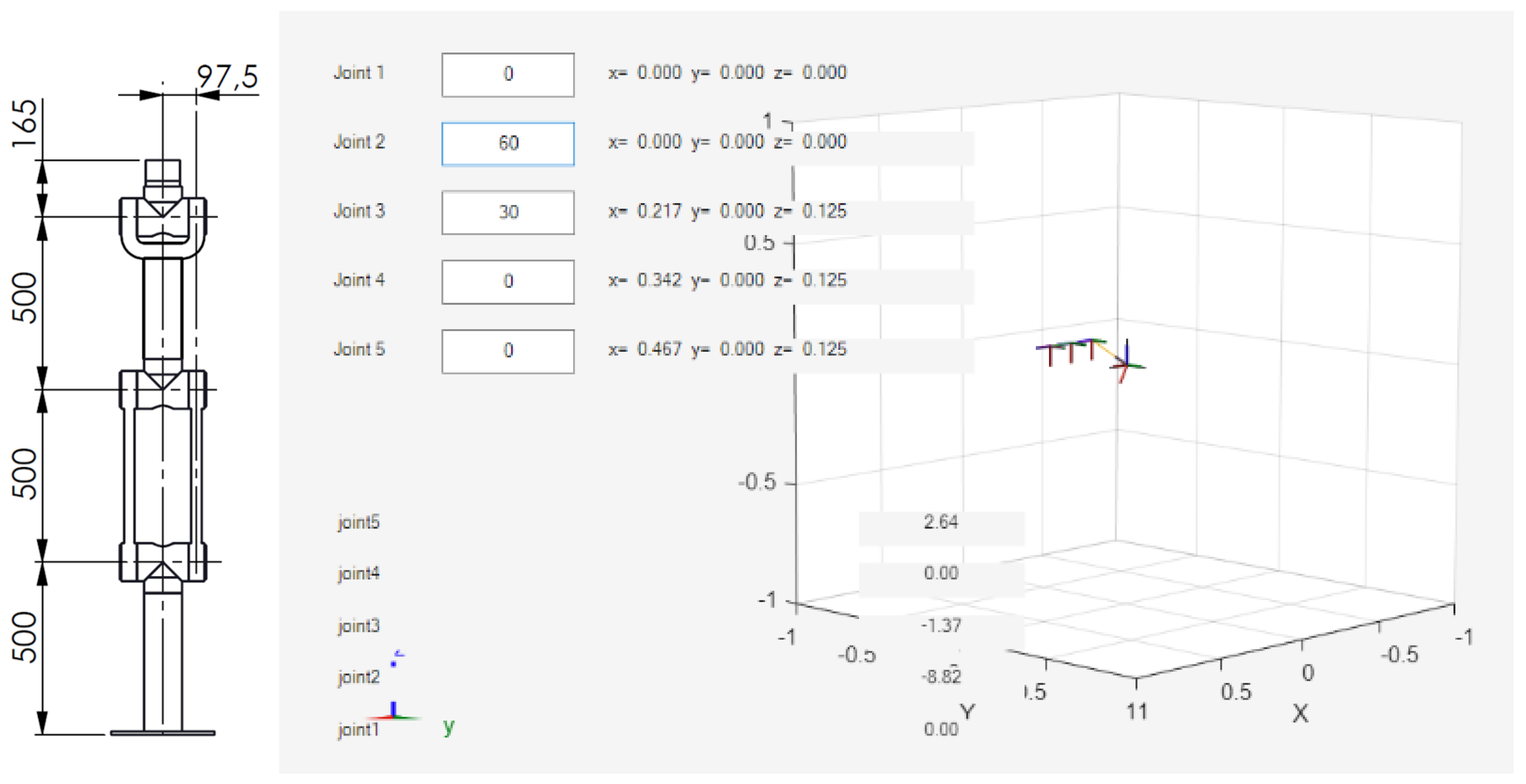
The next step is the design process, which will include the CAD modeling, the simulations, and the mass optimization. Parallel to this, the electrical and control design will be started too. There will be a test for 3D printing and assembly too. The CAD modeling and the simulation have already been initiated, which can be seen in Figure 4.
Figure 4.
CAD (left) and simulation (right) model of the presented 6DOF robotic arm.
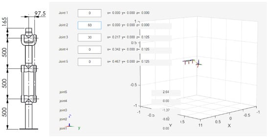
The simulation was developed in Matlab Robotic System Toolbox R2025b [21]. The simulation is capable of calculating the required torque at each joint at different arm angles. It will provide a fast calculation tool for motor sizing. In its current state, the angles of the joints can be given in degrees. In Figure 4, Joint 2 is rotated by 60° and Joint 3 by 30°. Then the position of the joints and the corresponding torque at the joint are calculated. In this test example, the same robotic arm presented in Figure 4 left is simulated. The load at the effector was 0.5 kg according to the requirements, and the masses of the arms were also included. The reaction torques were as follows: 0 Nm at Joint 1, −8.52 Nm at Joint 2, −1.37 Nm at Joint 3, 0 Nm at Joint 4, and 2.64 Nm at Joint 5. The simulation was compared with calculations according to the Denavit–Hartenberg principle [3]. The same result was obtained with the simulation tool and the calculation. Experimental validation remains future work.
4. Discussion
The conceptual design of a 6DOF robotic arm was started. During this stage, the conceptual design of the drive system was carried out. The four commonly used drive systems were evaluated for each joint. Each joint has a different task; therefore, its load capacity is different. The main focus was on the torque necessary to withstand. A cycloid gear drive was selected for the first two joints because these joints carry the highest load. A strain wave gear drive was chosen for the other joints, as they have reduced load requirements, but they need to have reduced mass. Other alternatives include a planetary gear drive and belt drive. The planetary gear drive is cheap, but it was discarded because of backlash. Sensor calibration requires precise positioning, so a belt drive was not suitable because of its flexibility.
The main advantage of using the presented systematic design is that a lot of concepts can be examined at the beginning of the design. Also, it allows a detailed requirement list. The limitation is that the exact load is not known at this stage, so attention should be paid when creating the CAD models and the simulations.
The final engineering justification for the selection of the robotic arm’s joints was guided by the total mass and structural design of the system, the corresponding benefits and limitations of additive manufacturing, and the outcomes of preliminary trial prints.
5. Conclusions
In this paper, the conceptual design of a 6DOF robotic arm suitable for sensor calibration was presented. The detailed requirement list was collected, and after that, the possible drive system of each joint was evaluated with a systematic design method. For the first two joints, a cycloid gear drive was used, and for the other joints, the strain wave gear drive was the best option. The next research task is the design process, which will include CAD modeling, numerical simulations, and optimization tasks.
Author Contributions
Conceptualization, D.T., C.H. and F.H.; methodology, D.T. and F.H.; software, C.H.; validation, C.H.; formal analysis, D.T.; investigation, D.T., C.H. and F.H.; resources, C.H.; data curation, D.T., C.H. and F.H.; writing—original draft preparation, D.T. and F.H.; writing—review and editing, C.H.; visualization, D.T. and C.H.; supervision, C.H. and F.H.; project administration, C.H. and F.H.; funding acquisition, C.H. All authors have read and agreed to the published version of the manuscript.
Funding
This research received no external funding.
Institutional Review Board Statement
Not applicable.
Informed Consent Statement
Not applicable.
Data Availability Statement
Data will be available on request.
Conflicts of Interest
The authors declare no conflicts of interest. The funders had no role in the design of the study; in the collection, analysis, or interpretation of data; in the writing of the manuscript; or in the decision to publish the results.
Appendix A
Decision Matrix for Transmission types.
Table A1.
Joint 1 (Base).
Table A2.
Joint 2 (Shoulder).
Table A3.
Joint 3 (Elbow).
Table A4.
Joint 4 (Forearm Roll).
Table A5.
Joint 5 (Wrist Pitch).
Table A6.
Joint 6 (Wrist Roll).
References
- Dehghani, M.; McKenzie, R.A.; Irani, R.A.; Ahmadi, M. Robot-mounted sensing and local calibration for high-accuracy manufacturing. Robot. Comput.-Integr. Manuf. 2023, 79, 102429. [Google Scholar] [CrossRef] [Scilit]
- Hajdu, C.; Lakatos, I. Calibration Measurements and Computational Models of Sensors Used in Autonomous Vehicles. Period. Polytech. Transp. Eng. 2023, 51, 230–241. [Google Scholar] [CrossRef] [Scilit]
- Siciliano, B.; Sciavicco, L.; Villani, L.; Oriolo, G. Robotics: Modelling, Planning and Control; Springer Publishing Company: Berlin/Heidelberg, Germany, 2010; p. 632. [Google Scholar]
- Pesti, R.; Csík, D.; Sarcevic, P.; Odry, A. Measurement System for the Calibration of Accelerometer Arrays. Analecta Tech. Szeged. 2024, 18, 30–37. [Google Scholar] [CrossRef] [Scilit]
- Pradeep, V.; Konolige, K.; Berger, E. Calibrating a multi-arm multi-sensor robot: A Bundle Adjustment Approach. In Experimental Robotics: The 12th International Symposium on Experimental Robotics; Springer Tracts in Advanced Robotics; Springer: Berlin/Heidelberg, Germany, 2014; Volume 79, pp. 211–225. [Google Scholar] [CrossRef] [Scilit]
- Nguyen, V.T.; Ngo, T.Q.; Duong, M.K. Design and Fabrication of a 6-DOF Articulated Robotic Arm for Research and Educational Applications. Int. J. Robot. Control Syst. 2025, 5, 2379–2398. [Google Scholar] [CrossRef] [Scilit]
- Tsai, R.Y.; Lenz, R.K. A New Technique for Fully Autonomous and Efficient 3D Robotics Hand/Eye Calibration. IEEE Trans. Robot. Autom. 1989, 5, 345–358. [Google Scholar] [CrossRef] [Scilit]
- Beltrán, J.; Guindel, C.; de la Escalera, A.; García, F. Automatic Extrinsic Calibration Method for LiDAR and Camera Sensor Setups. IEEE Trans. Intell. Transp. Syst. 2022, 23, 17677–17689. [Google Scholar] [CrossRef] [Scilit]
- Li, X.; Xiao, Y.; Wang, B.; Ren, H.; Zhang, Y.; Ji, J. Automatic targetless LiDAR–camera calibration: A survey. Artif. Intell. Rev. 2023, 56, 9949–9987. [Google Scholar] [CrossRef] [Scilit]
- Kang, Z.; Wang, L.; Sun, A.; Xu, S.; Wang, B. Two-step calibration of 6-DOF industrial robots by grouping kinematic parameters based on distance constraints. Measurement 2024, 235, 114906. [Google Scholar] [CrossRef] [Scilit]
- Shirafuji, S.; Goto, H.; Zhang, X.; Okuhara, K.; Takamura, N.; Kagawa, N.; Baba, H.; Ota, J. Visual-Biased Observability Index for Camera-Based Robot Calibration. ASME J. Mech. Robot. 2024, 16, 051010. [Google Scholar] [CrossRef] [Scilit]
- Pahl, G.; Beitz, W. Konstruktionslehre: Methoden und Anwendung; Springer-Lehrbuch; Springer: Berlin/Heidelberg, Germany, 1997; Volume 17, p. 763. [Google Scholar] [CrossRef] [Scilit]
- Available online: https://gtt.sze.hu/images/Mechatronika/Mechatronikai_rendszerek_tervezese.pdf (accessed on 5 May 2026).
- Leone, S.; Lago, F.; Pisla, D.; Carbone, G. A Systematic Approach for Robotic System Development. Technologies 2025, 13, 316. [Google Scholar] [CrossRef] [Scilit]
- Younis, M.; Nasser, E.; Nasser, A. A Methodology for the Design of 6D Robotic Arm. In Proceedings of the International Exchange and Innovation Conference on Engineering & Sciences (IEICES), Fukuoka, Japan, 21–22 October 2021; Volume 7, pp. 329–335. [Google Scholar] [CrossRef] [Scilit]
- Zsáry, Á. Gépelemek II. [Machine Elements II]; Tankönyvkiadó: Budapest, Hungary, 1991. [Google Scholar]
- Hrdlička, F. 3D printed planetary gearbox for robotic arm joints. Des. Mach. Struct. 2022, 12, 38–46. [Google Scholar] [CrossRef] [Scilit]
- Younis, O. Building a Cycloidal Drive with SOLIDWORKS. Available online: https://blog-assets.solidworks.com/uploads/sites/3/Building-a-Cycloidal-Drive-with-SOLIDWORKS.pdf (accessed on 10 May 2026).
- Pacana, J.; Pacana, A.; Oliwa, R. Possibilities of Using Selected Additive Methods for the Production of Polymer Harmonic Drive Prototypes. Materials 2023, 16, 4073. [Google Scholar] [CrossRef] [Scilit]
- Pahl, G.; Beitz, W.; Feldhusen, J.; Grote, K.-H. Engineering Design: A Systematic Approach, 3rd ed.; Springer: London, UK, 2007. [Google Scholar] [CrossRef] [Scilit]
- Available online: https://www.mathworks.com/products/robotics.html (accessed on 9 May 2026).

Disclaimer/Publisher’s Note: The statements, opinions and data contained in all publications are solely those of the individual author(s) and contributor(s) and not of MDPI and/or the editor(s). MDPI and/or the editor(s) disclaim responsibility for any injury to people or property resulting from any ideas, methods, instructions or products referred to in the content. |
© 2026 by the authors. Licensee MDPI, Basel, Switzerland. This article is an open access article distributed under the terms and conditions of the Creative Commons Attribution (CC BY) license.